


AON
-
Posts
2,770 -
Joined
-
Last visited
Content Type
Profiles
Forums
Gallery
Events
Posts posted by AON
-
-
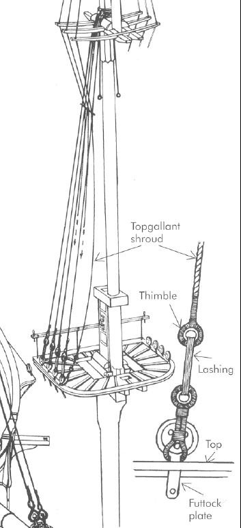
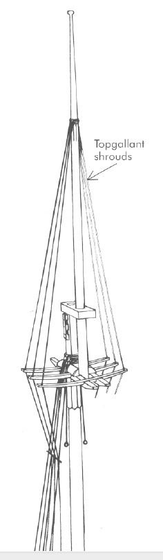
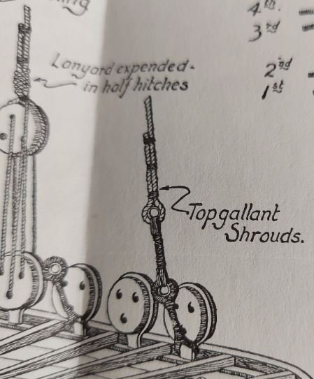
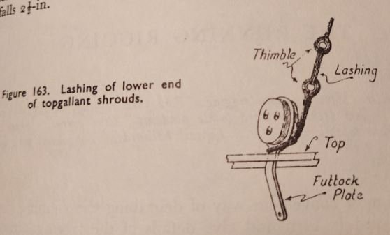
Reading The Anatomy of Nelsons Ships (C.Nepean Longridge) page 233 and looking at the image in Rigging Period Ship Models - Square Rigged (Lennarth Petersson) page 11:
"The first pair is doubled in the usual manner, the third shroud goes over the mast head with an eye splice."
"Each shroud reeves through a hole in the outer end of the top mast cross trees, where it is served. Inclined inwards, the shrouds pass between the topmast shrouds, and inside the topmast futtock stave."
"The top gallant shrouds are lashed to the first, third and fifth futtock plates on the fore and main masts, to the first and third on the mizzen."
-
-
Seems the foot or bottom of the column is pocketed into the deck (hidden or dashed lines below the top surface of the deck in the image).
The head or top also is recessed into the beam from one side allowing it to slide out once the beam is lifted.
-
Thank you Siggi,
I have been wondering how they would swing a column up if it were hinged without the foot of the column being rounded to allow it to pivot, or even pull a column out. Hinged or not... of course they jacked the overhead beam up a smidgen to create the necessary clearance!
DUH.
-
I had six square frames installed... had to remove five of them and then alter my bow and stern supports as they were wandering again.
The Plexiglas inserts that slide into the notches was out of square. I had secured it once before but apparently it didn't hold.
This time I added a brace across the top, and then drilled and screwed the sides.
It will never move again.

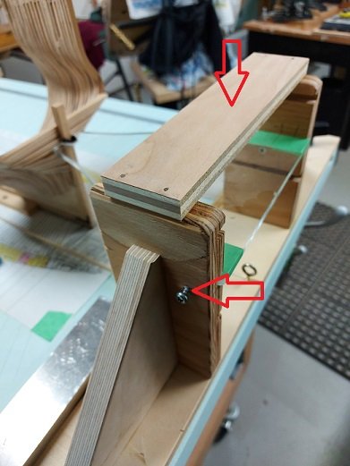
The frames are back up and aligned properly.
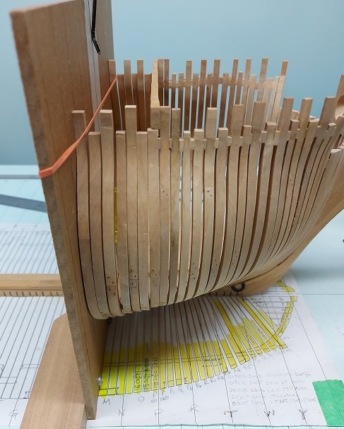
The next four frames are underway.
-
-
-
-
-
Good morning Druxey (et al)
I finally got back to it.
Is this image more along the lines of what you would have expected?
Alan
- cog, GrandpaPhil and Canute
-
 3
3
-
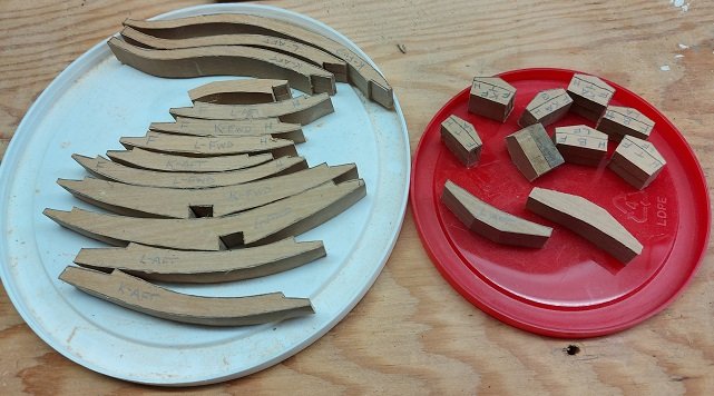
Unfortunately I do not have a mill, nor do I have the room in my shop to add one. Might consider moving a wall. It would be the third time.
I cut my 4x13 blanks from 4x6x60 inch castello boxwood stock, plane them to thickness (within reason), cut those pieces in half and rubber cement them into matching pairs. I trace my timbers onto the top of one blank set and scroll saw the pieces out keeping well outside the line. This gives me the port and starboard halves with one cut. Then the curves are sanded to the line on a oscillating drum sander. The flats are sanded to the line on my disc sander. I wish there was a market for sawdust.
The pieces are dry fitted on top of the pattern (my drawing) and once satisfied I then separate the halves and yellow wood glue the frames, floor and chocks together. This is done on the paper pattern, with the pattern under a thin plastic sheet, to assure everything is correct. The assembly is allowed to dry and cure for just less than 24 hours (probably 20 hours) then attached (glued) to the build and allowed to set another 20+ hours before the next frame is glued next to it.
I have three frames at various stages going at once so I have less waiting time.
I was taught how to properly use rubber cement, and to cut two pieces at once by a member of our local club.

Most everything else I learnt from this forum from people like you!

All the mistakes I've made I learnt on my own.

-
Druxey,
It should be easy to do. I opened the file and tried to adjust things and it was a nightmare, so I started it over as a new file ... and it will need some trial and error adjustments as yet.
Everyone,
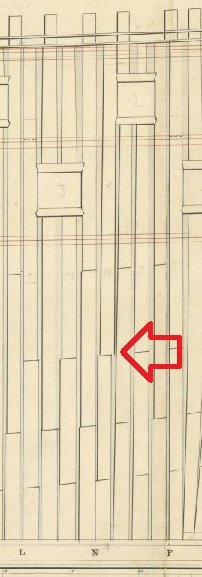
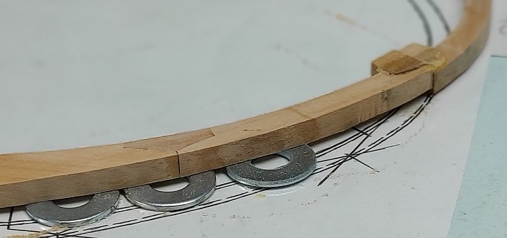
I got going on my first stepped frame. N-Forward steps forward about 2-1/2 inches ( 0.04" at the build scale) to reach the upper gun port and receive the notches for the upper and lower cills as can be seen in the snip from the framing plans.
I found some flat washers I could use as supports while the glue set. One side has been roughly filed down and needs to be finish sanded the last little bit.
Full disclosure, I originally forgot to step it even though I have it marked in BOLD RED on my plan. Had to take it apart and redo the chock thicker to accommodate the step.
-
-
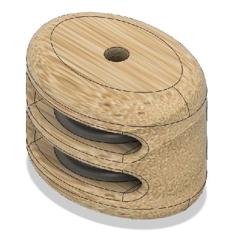
Yesterday I completed modelling and creating drawings for all the blocks. This includes the parrals which I had made a great error with.
I had not realized the different sizes of parrals had different diameter trucks to suit the different size ribs. It is only logical but I was fixated on the one drawing I had found with dimensions. It makes perfect sense why some trucks look like balls whereas others are elongated.
So for anyone interested the package is below as a PDF.
Today I go down to the shop.
-
-
-
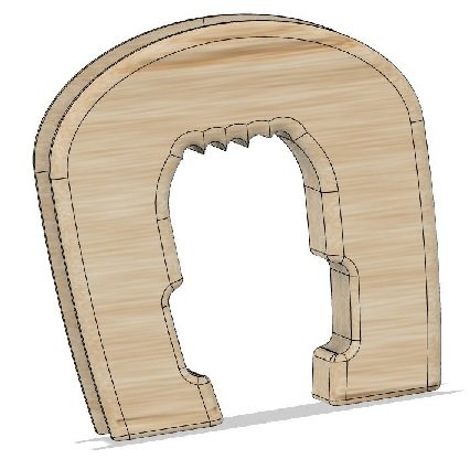
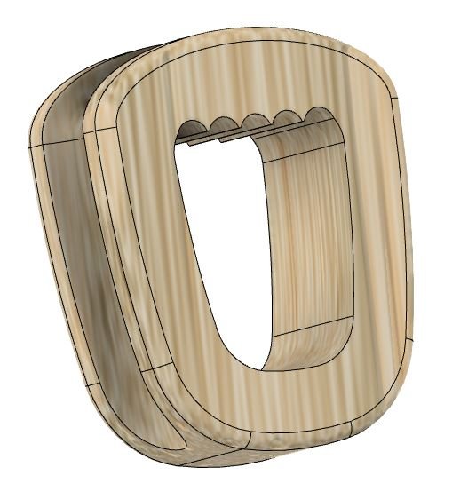
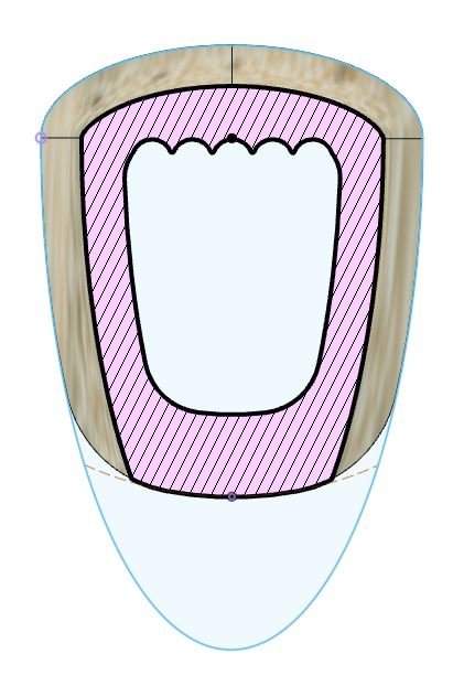
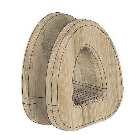
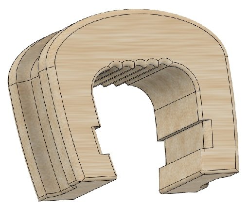
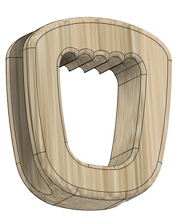
take two, or twenty two.
I've reworked the closed heart.
I've included a sliced or cross section view showing the shape is made of two ellipses (top and sides) and one circle (bottom) off one common centre (the black dot).
I added fillets (radii) to the bottom outside and inside corners to soften/blend the edges/contour.
I honestly think I have it this time.
-
-
-
I suppose you are correct.
If I ignore sketches in various books and look at Steels figure (curiously missing from Rees) or even the photos on the Syren website I see what you are describing.
I'm certain I can do better.
- GrandpaPhil, druxey, JpR62 and 4 others
-
7
-
My updated count of blocks is numbered at 1,323.
I've completed 16 models and template drawings to allow me to make them. These are on regular "A" size or letter size paper (8-1/2" x 11"). Most are modeled in strips of 6 blocks with ample space between each to cut them from a sized strip of wood.
Sizing standard single, double, treble and four fold blocks was easy enough as Steels (and Rees) give the proportions. Sizing the others meant finding the info. With the help of this site I was directed to Steels' block making section of The Elements and Practise of Rigging and Seamanship, Vol. 1. In the section entitled the Practice of Block Making ( https://www.hnsa.org/manuals-documents/age-of-sail/the-elements-and-practice-of-rigging-and-seamanship/block-making-vol-i/ ).
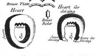
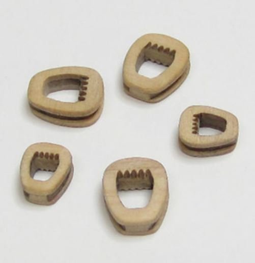
The open heart size given in tables is the length or height of the wider side, the cheek. The width of the cheek is approximately 3/4 x the height. The breadth has a single or double groove into which the standing rigging rope or strop wraps about. It is twice the size of the rope or three times the size of the doubled strop. This means the outside lips or wall of the heart holding the rope or strops into the groove is half the size of the rope/strop. I assume the thickness of the heart (outside to inside opening) is at least 1-1/2 x the rope size. This means the cross sectional depth of wood excluding the groove would be at least equal to the rope size. When I modelled it I sketched in five wrappings of the lanyard, checked where the outside wrapping fell and adjusted the thickness to suit. The inside flat of the heart is said to have four or more grooves for the lanyard. I put five in mine.
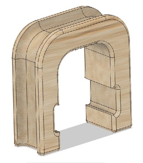
The closed heart size given in the table is once again the length or height of the heart. The inside will have the same number of lanyard wrappings as the matching closed heart mentioned above. The width of the heart (distance to the outside of the two legs) must locate the strop outside of whatever the open heart is spreading the strop to get around. The two hearts for the forestay and fore preventer stay to the bowsprit are sized to allow the jib boom to pass through underneath it. My jib boom measures 17" across the flats of the hex shape at its foot end. So the legs of my hearts are sized to drop the strops outside of 17" and the thickness is such that the top of the heart can accommodate 5 wraps of the lanyard.
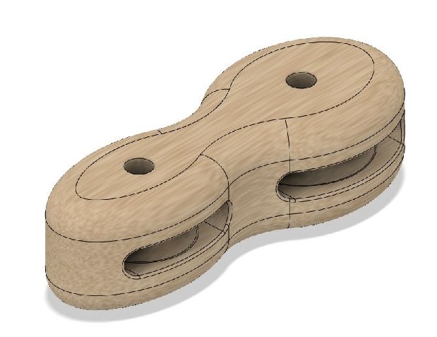
The long tackle block is comprised of two sheaves, one above the other. It's size is the length of the cheek. Steels reads that it is 2/3rds longer than the proportion for a single block at one sheave to be 2/3rds less than the other, and made agreeable to the size of the rope. So we look at the rope size and calculate the various dimensions at the larger top sheave. The lower sheave is 2/3rds the diameter of the upper but similar thickness as it is the same size rope reeving through it.
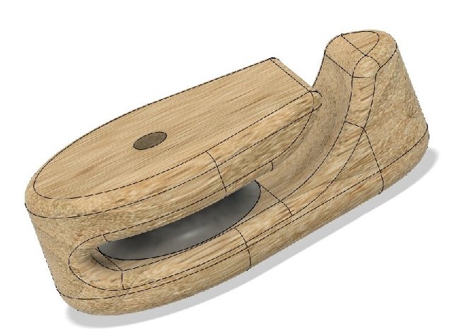
The snatch block is proportioned by the rope, leaving 2X the length for the score and lashing, tapered from the sheave to the lash end to 1/2 the breadth and thickness at the sheave. BUT... the viol or voyol block, which is a snatch block is 10X the thickness of the sheave hole which is 3/8ths more than the thickness of the sheave. The thickness of the sheave is 1/10th more than the diameter of the viol (the rope), and the diameter of the sheave is 7X the thickness. The breadth of the block is 8X the thickness, and the thickness to be 2/7ths of the length. This was difficult to understand at first until I started with the two givens. The rope size is 13.5" (= 4.3" diameter) and the block size (cheek length) is 57". Then I worked backwards: the sheave thickness is 1/10th larger than the rope diameter (= 4-3/4"), the sheave hole thickness is 3/8" larger (= 5-1/8"); and the sheave diameter is 7X the sheave thickness (= 33"); the block thickness is 2/7X the length (= 16") and the block breadth is 8X the thickness of the sheave (= 34.4").
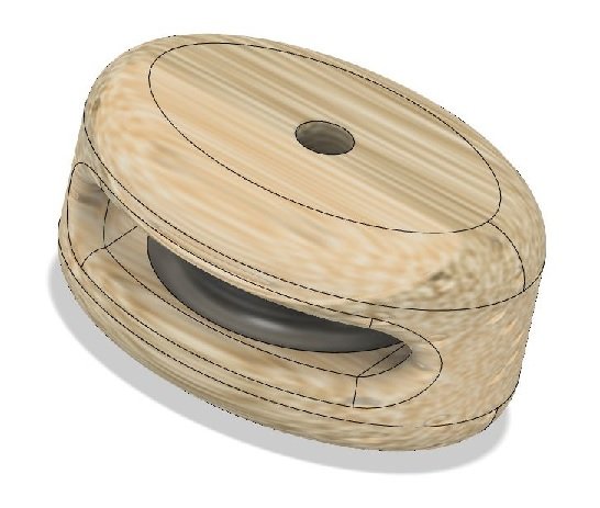
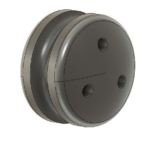
The dead eye size is the outside diameter, and they have a thickness 1" more than half their diameter. Three holes are bored through the dead eye, sized for the lanyard, in a triangular pattern, on a circle of 1/4 less than the diameter of the block (or 3/4X the diameter of the block). I made my dead eyes a little thicker and adjusted my hole circle slightly so they might be easier to make. The circumference is grooved to accept the stay rope.
Once done I realized this did not account for the gun rope blocks. I found one article in the NRG magazine 1962 issue 12-1 (The Sizes of Gun Tackles and Breechings by Edwin Newell Rich) which gave the rope and block sizes for the various guns on the various sizes of RN warships. I have both single and double block sizes of 6-1/2", 8" and 10" for 2-1/2" and 2" gun, train, and gun port tackles. My breech ropes are 6", 5" and 4" for the 32, 18 and 9 pound guns.
I received my "good to go" from the eye doctor, so I can get back to making my square frames now.
-
I spent a portion of the early morning reviewing two walk through tour videos, and it appears the public were not allowed in that area.
I also noticed they seem to never take any pictures of the one thing you are looking for at the time.
I have a CD of pics that was copied and distributed at one of our club meetings... and of course any image of the area is AWOL.
-
If you consider the bowsprit in the sense of a mechanical fulcrum, as I see it, the knights head is the pivot point. All lines (or ropes) outboard are either pulling down or up, except the guy pendants which are keeping it from sliding forward (unstepping), the gammoning is doing both, and the foot of the mast in the step is holding that end of the fulcrum stationary.
I think the partners (housings) are beefy fillers in an attempt to assist in keeping the mast from shifting, and keeping water from passing to other levels.
Possibly someone in the know might jump in.
-

How are bowsprit shroud deadeyes & collar attached to bowsprit?
in Masting, rigging and sails
Posted
Jason
It seems some were lashed as discussed above where as others were a single splice strop making an oversized loop of rope (line).
The deadeye (or thimble which is the example I am looking at in The Anatomy of Nelsons Ships, page 235) is fitted with the "item" inside the strop, rope in the groove and wrapped around it, then seized tightly to it.
Possibly this is what was done in your case.