


AON
-
Posts
2,771 -
Joined
-
Last visited
Content Type
Profiles
Forums
Gallery
Events
Posts posted by AON
-
-
helm port, Helm Port, Helm Port, HELM port, HELM PORT, helm port, Helm Port, Helm Port, HELM port, HELM PORT, helm port, Helm Port, Helm Port, HELM port, HELM PORT, helm port, Helm Port, Helm Port, HELM port, HELM PORT ( = rudder hole)

- garyshipwright, mtaylor, gjdale and 3 others
-
 6
6
-
Paul
I hope the pipe insulation idea works for you. It is cheap option if you've got the item laying around the house.
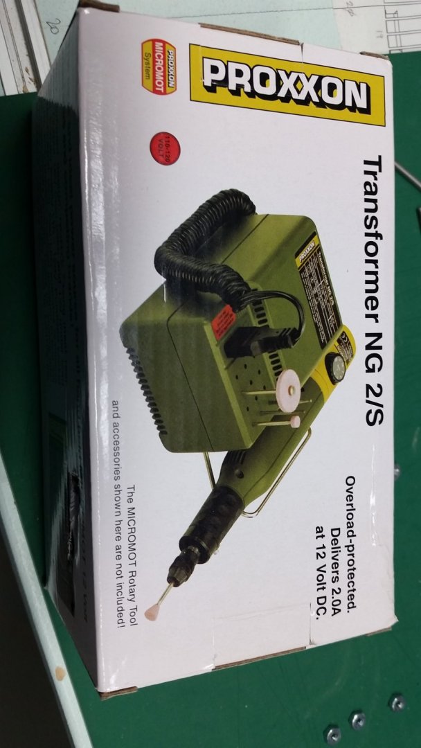
I have since purchased a Proxon electric sander and transformer... but that is a considerable expense for one small well.
- popeye the sailor and pwog
-
2
-
Good evening Paul,
I detest sanding.
I mean, I start with all the best intentions, with real honest ambitious resolve.... but sometimes it just never seems to end.
It just goes on, and on, and...
I find you just have to stick with it and tune into a radio station with some good music you can get lost in.
I also experiment with all kinds of different backers for sand paper, including a small cut off length of pipe insulation foam tube. It is similar to those noodles kids use in the swimming pool. I stick the paper into the slot, wrap it around the round pipe insulation and grip it as best as I can... then get back to work. It will form to quite a few odd shapes and is forgiving to the grip.
Alan
- popeye the sailor, FriedClams and pwog
-
3
-
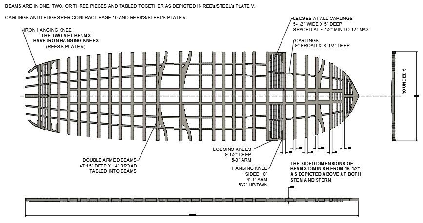
Updated the image of the Upper Deck Beams in post #1096 dated September 5.
Below is the Gun Deck Beam image.
I will not be doing the Orlop deck as it will not be seen very well.
The five beams at the Waist will be made insitu following the Quarter Deck rounding at 8-1/2" (0.133" at 1:64 build scale).
Mark: FYI - my upper deck NMM plan shaped tiller hole allows 30° of travel in each direction
-
-
-
-
happy your back!
-
First let me make it clear that I am a beginner at ship modelling and every day is a new and steep learning curve for me. Yes I have chosen to dive into the deep end.
I am very grateful for all the help I get on the forum (yes, you and you and ...), from members of my local club (Model Shipwrights of Niagara), and from various collections of magazines I've been lucky enough to acquire for a short period before gifting them to someone else in our club, including the older NR Journals I've been given and those I've collected since becoming a member. I feel that must be the luckiest guy in the world!
The book I mentioned was "Anatomy of the Ship - The 74-gun Ship Bellona" by Brian Lavery published by Conway Maritime Press Ltd, ISBN 0 85177 368 0.
My error when I suggested it was Conway's book... it is Brian Lavery's. Although it is said to have errors I find it a great reference to understanding and identifying items. I just need other sources to verify what he shows me.
The NMM plan No. J2938 of HMS Elephant shows nothing in the way of carlings, ledgers and knees.
I have the contracts of both Bellerophon (No. ADT 0009) and Elephant (No. ADT 0030) which are identical except for some notations in the margins.
I completely transcribed (typed out) the contract with my explanations, definitions, and references to my library books and pages/images/descriptions so I can find them again down the road. Having done that, I find I've forgotten most of what I had learnt so thank goodness I noted where to find it again.
I have REES's Naval Architecture (1819-20) book with plates, and I have copies of Steel's Plates which seem identical that I reference. I've study a number of other plans on the NMM website and builds here on this forum of which Mark's Bellona and Gary's (your) Alfred are my go to builds at the moment.
You are correct regarding the carlings under the furnace. They are specified at being 12 inches broad and 12 inches deep. I've drawn them at 12 " broad, and the depth of which 2" are to project above the upper deck beams, which I did not model as I will be referring to the contract when building and installing these. The same Idea for the coming carlings ... but at 1:64 scale who will notice a sliver of difference.
I will re-read the contract carling location descriptions for the upper deck.
Thank you
- toms10, garyshipwright, mtaylor and 4 others
-
7
-
Thank you for the beam plan Mark.
I've copied it to my reference library... now I just have to remember it is there.
I had seen some of the different features in some other plans. This is different than what Conway drew in his book. I am not surprised as there have been a few other items noted.
The thing that really throws me is that I specifically bought the Elephant deck plans (a sister ship) from the NMM and they don't fit the ship for length!
Having spent 40 years in engineering I am puzzled as to why that major inconsistency should confuse me!

-
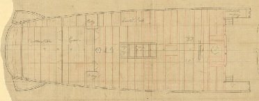
Getting near the end of the Upper Deck Beam Layout.
Looking at various references that don't agree with each other plus my NMM deck plan drawing of HMS Elephant is too long for that ship.
I've yet to add the Knees... and then check it again.
Here is what I have so far... (image updated 13 SEP 2020)
-
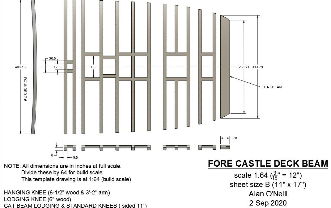
The Forecastle deck beam layout gave me a small headache.
First the rounding or camber was said to be 7-1/2" on page 2 of the contract, and then it is 6-1/2" on page 17. I focused far too much on this... once I came to my senses and realized my scale of 1:64 scale build difference was 0.015" I just picked the larger number.
Next I didn't understand what the cat beam was. It is said to be 2'-4" broad (wide or sided) and 10" deep. I discovered it is directly below the cat tail (the part of the cathead that crosses the deck athwart ships at the head. I found it in Rees's Plate IV, and also in The Anatomy of Nelson's Ship's page 79, figure 44. As it is a mere 2" (0.03" to build scale) thicker than the forecastle deck beams (8" moulded) I decided to ignore the 10" as no one will see or notice it.
I started aft and worked forward with my layout. When I got to the mast I realized the roughly measured beam spacing did not fit the space on the model. I closed up the first three beams aft from 36" to 24" and things lined up at the mast. That is two feet missing from the plan.
Just beyond or forward of the mast is a stairwell. The space (a large gap) between the beam forward of the stairwell and the cat beam was not there. I measured the deck plan and then the model and there was a five foot difference. My model deck length is 43'-4" and the contract specifies 42'-9", a mere 7" difference or 0.11" at my build scale. The museum plan deck measures roughly 48'-4" long.... the missing 5 feet!
The plan clearly shows carlings (fore/aft joining beams) in only two locations: 1) at mast, and 2) under the belfry. I added them at the gratings, stove pipe and stairwell openings.
So this is what I have. (02 Sept 2020 replaced image and dwg with updated version)
- druxey, mtaylor, GrandpaPhil and 5 others
-
8
-
-
Played with it some this morning and this is the best I can get.
Still has some lines that should not be there.
Also I know the knee legs are tapered with rounded ends. I can do this when they are built.
screen capture and downloadable PDF below.
Moving on to the Round House deck.
- albert, bruce d, Edwardkenway and 7 others
-
10
-
Generated the dwg ...but the program jumbled a couple of lines to the right at the main mast location. I've no idea why.
If I cannot get it to work properly I can sketch them in with a pencil.
- bruce d, Edwardkenway, GrandpaPhil and 4 others
-
7
-
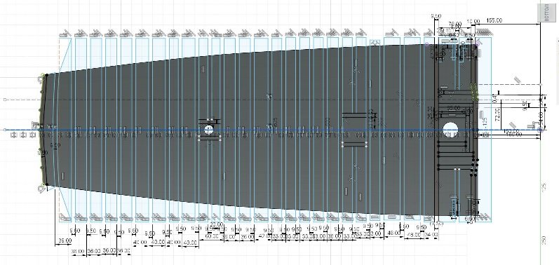
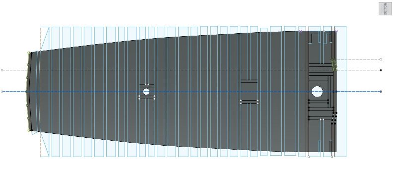
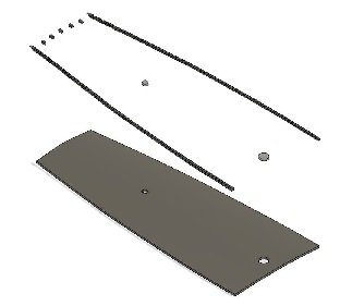
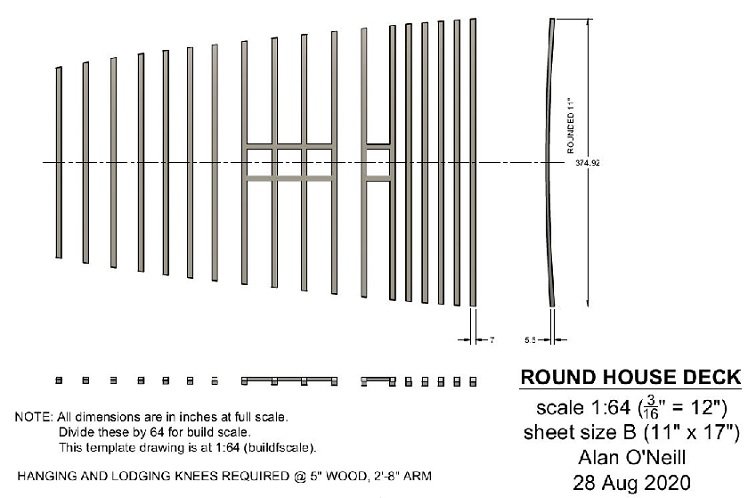
I got the model done. Just need to import it to a sheet at 1:64 scale for the template.
three pics below
1- a layout with a mess of dimensions
2- same but cleaner looking layout with the dimensions hidden. You can see the shaded areas that will be cut away.
3 - the end result. I roughed in the hanging and lodging knee as blocks in the bottom right corner and just the hanging knees in the top right corner.
I'll get the drawing template made than do the roundhouse deck beams.
- GrandpaPhil, garyshipwright, gjdale and 6 others
-
9
-
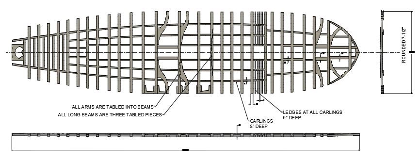
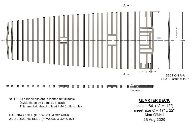
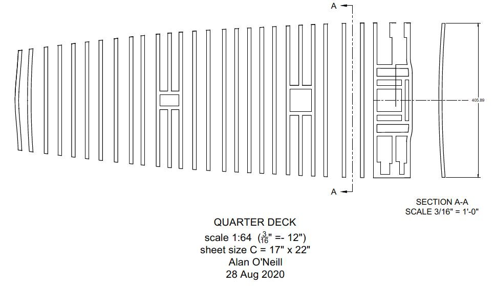
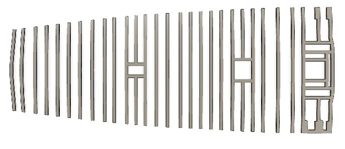
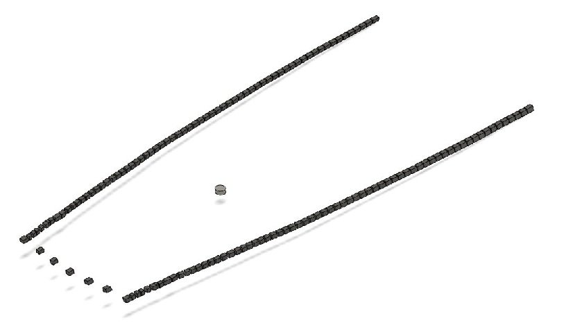
My progress with Quarter Deck layout.
From the page 15 of the contract I found the quarter deck was rounded (cambered) 8-1/2 inches (21.6 cm) for deck water runoff. The beams were sided (thickness forward to aft) 9-1/2" (24.1 cm) and moulded (thickness or depth top to bottom) 8" (22.8 cm).
At 1:64 scale these numbers are as follows:
rounded 8-1/2" (21.6 cm) = 0.133" (3.4mm)
sided 9-1/2" (24.1 cm) = 0.148" (3.8 mm)
moulded 8" (22.8 cm = 0.125" (3.2 mm)
First I made a copy of my "master model" and renamed it Quarter Deck. I worked on this copy.
I drew my outlining lines along the perimeter and around the mast, extruded my deck slab, then sketched the rounding or camber at the forward facing end of the slab and cut that out. When I started to outline the forward most beam I noticed the main mast as compared to the reference plan was missing. I had it too far forward. This was corrected on the master model and the location of the other masts were verified. Then the quarter deck copy was replaced and the slab had to be re-created. There is always time to do it over.
These are the results. Now I sketch in the beams with one lodging and hanging knee at each end as per the museum plan and the contract.
I will post again when I have this one done.
-
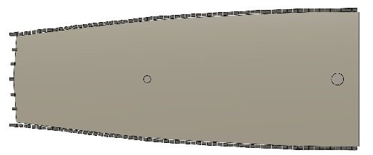
Good morning everyone. I had my eye surgery (cataract removal and new lens implant) last Friday and it has been amazing. The actual surgery was over before I realized it had started. The most painful part was when they removed the tape holding the IV plug in the back of my hand just prior to my discharge from the hospital. I cannot recall my vision being so vivid and crisp. Yesterday I went to the optometrist to have the lens removed from the frame as wearing my glasses with both lenses gave me a headache and simply ruined the view. I get the other eye done on the 25th of September.
Meanwhile I am not allowed to do quite a few things and one is to work in the shop... a sawdust issue.
So I've decided to work on my deck templates. There are five in total: roundhouse, forecastle, quarter deck, upper deck, and gun deck. I spent a part of yesterday refreshing myself with Fusion 360 and my 3D ship model. I pulled out my Museum plans and measured the height of each deck at their extreme upper surface forward and aft location. Then I copied my model and sliced it at the quarter deck so I had the outside perimeter of the deck (inside of the hull) identified. The result is below. Now I need to layout the deck framing to create the templates.
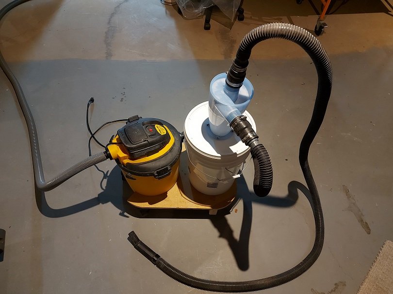
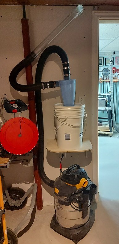
Prior to my surgery I added cyclone dust separators to my two shop vacuums. I found a supplier that stated the minimum kW rating required to work and then checked my shop vacuums HP rating (conversion to metric was necessary). The filters were constantly clogged and emptying them was messy job. The cyclone separator spins the dust around the outside cone of the housing to separate the dust with centrifugal force. It removes 98% of the dust per the specifications. The last 2%, a fine dust that is too light to drop out flows through to the vacuum filter... there was nothing seen on the floor of the vacuum canister.
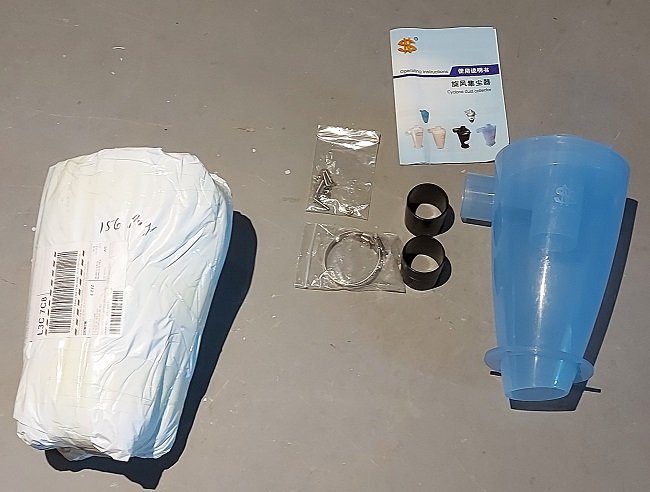
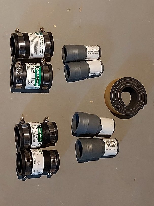
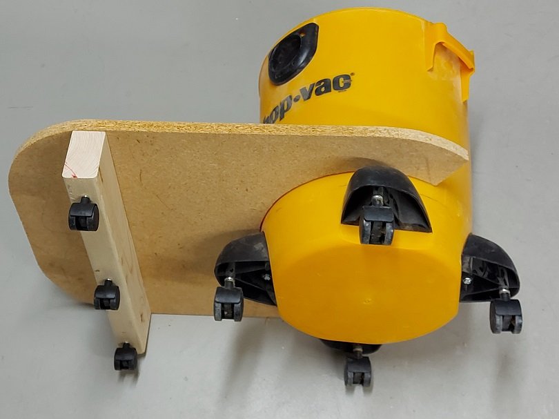
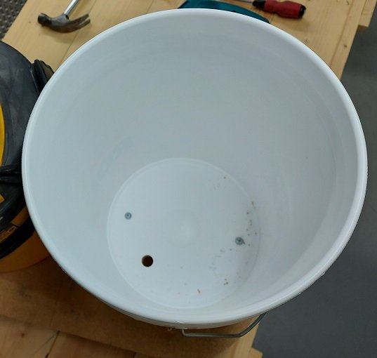
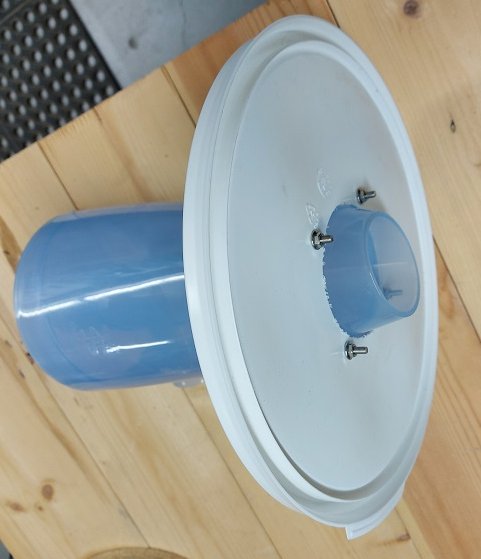
I looked at a few YouTube videos before I began the process. The sparators were supplied with two couplings and hose clamps but as they are metric and my hoses are not I needed to purchase some additional fittings (flexible rubber couplings and hose barb fittings from Canadian Tire), plus I used some adhesive backed 1/4" rubber gasket material (McMaster-Carr) where the fit was still sloppy. I built a mobile deck for the smaller vacuum that moves around the shop, added casters that were horded from old tables or chairs, and a wall shelf for the stationary vacuum that is connected to the Lee Valley Tools dust collection system that was gifted to me by a good friend. I also bought four 5 gallon pails and two lids from RONA. One pail acts as a "cup holder" for the other pail, and the lid was cut out and drilled to mount the cyclone separator. The "cup holders" are screwed down and a hole is drilled through the deck to break the suction that normal makes it difficult to pull stacked pails apart.
They work like a charm!
Photos below and also a short video of centrifugal force at work.
- GrandpaPhil, ccoyle, druxey and 8 others
-
11
-
Thank you for the well wishes everyone.
Dan
I've seen some 2D drawings of the mast pieces and stepped sections but no 3D renderings. I know some people have some trouble understanding more complex 2D drawings... and I am an avid fan of 3D models inserted into a 2D drawings . IMHO they add exceptional value at no extra cost!
Please let me know if you stumble across a model. If not I might have a stab at it down the road.
-
So much happening.
First I've added cyclone separators to my shop vacuums... more on that later.
Got everything ready to begin the square frames... hoping they will be easier especially when I can see clearly.
Tomorrow I go for surgery on my left (worst) eye. Then in about 5 weeks I get the other one done. I can't wait to see clearly again. Possibly I will be able to see the royal cypher on my 3D printed 9 pound gun barrel in the dark display case after all!?!
-
-
-
Without having experienced it, my technical training in fluid dynamics suggests that with the thickness of the rudder blade and the sharp change in shape (tail end of the blade) there would be considerable turbulence experienced which would be felt back through to the tiller, possibly resulting in shaking things up a bit.
I am certain each country did "borrow" any improvements in design that they discovered in captured warships of the time, and it was a busy time full of design changes.
Kurt, although I look forward to reading a short synopsis on the subject here, I appreciate the availability of the full article and will be getting it.
Thank you.
Alan
-
It has been awhile and much has happened. It is very warm in the Niagara Peninsula but I don't want to complain too loudly as winter is coming sooner than we'd like.
I hope everyone has been well.
I am just about done my fairing but continue to drag my butt. Recently I found tools and methods that work for me. A short bow sander for the outboard side and a 3 inch piece of foam pipe insulation onto which I wrap my sand paper for inboard and finishing the outboard. This last one is quite comfortable and contour friendly. I find the bow sander a bit monotonous and hypnotizing... had to give myself a good shake now and then to assure I was paying attention to the work at hand.
It has become difficult to see any close detail as my left eye is completely foggy (vision gone) and my right eye following it more quickly than I like. I hope to have cataract surgery to correct my vision issue before winter. Measurements have been taken and I await a phone call to schedule the event so long as day surgery isn't cancelled again due to any covid outbreak.... I still get a darned eye injection every 10 weeks to boot! Hopefully that will be done with soon.


HMS Bellerophon 1786 by AON – scale 1:64 – 74-gun 3rd Rate Man of War - Arrogant-Class
in - Build logs for subjects built 1751 - 1800
Posted
As soon as Druxey corrected me I was brought back in my mind to grade school and the teacher assigning us homework to print the new words in our lesson book 50 times and she would check that it was in fact done the next morning. I think I'm gonna need a bigger pencil.