


AON
-
Posts
2,593 -
Joined
-
Last visited
Content Type
Profiles
Forums
Gallery
Events
Posts posted by AON
-
-
-
-
-
I've gone down to check and the warpage is gone.
Heart attack averted.
I've set it down onto the table top (build board) and set my weights on it to hold it for now
As I haven't worked with items that were not nailed or screwed to something much more substantial I have not experienced this before.
My cutter of 16 years ago was quite a bit smaller and all the same wood (balsa) so this never happened.
1cm.... 1mm ... and that is why I hated my slide rule (1972) and I love my calculator , it never puts the decimal place in the wrong spot.
I'll make the correction above.
Going to layout the false keel bolt holes and staple locations now.
Then I have to read up on blackening copper wire for the staples.
-
Sunday 27 March 2016
First opportunity to work on the model since last weekend.
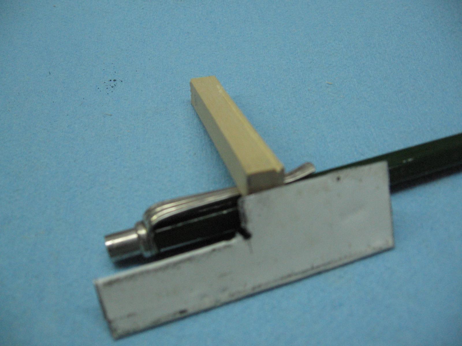
Let me start by saying how extremely happy I've been with last weekends work.I made a new scraper and threw that one out. Filing the cutting edge was a problem for me.
Devised a new method using my dremel and a cutting wheel. This worked much better.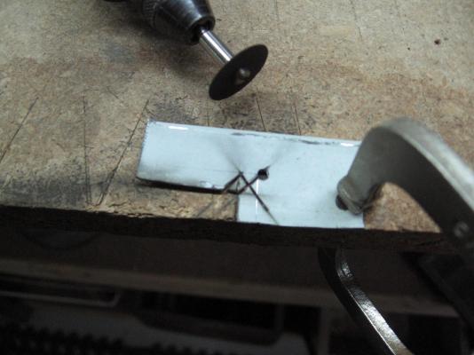

Cut the rabbet on one side of the keel. As everything has been going too well I kept double checking because I knew this was all going too well. Was I cutting the wrong side? Nope! So far so good.
Cut the rabbet on the other side... was I doing this one wrong? Nope! How did I manage that?
Glued the false keel to the keel... did I glue it to the top instead of the bottom? Nope? Did I put it on backwards? Was it the right section? No and Yes... still going well.

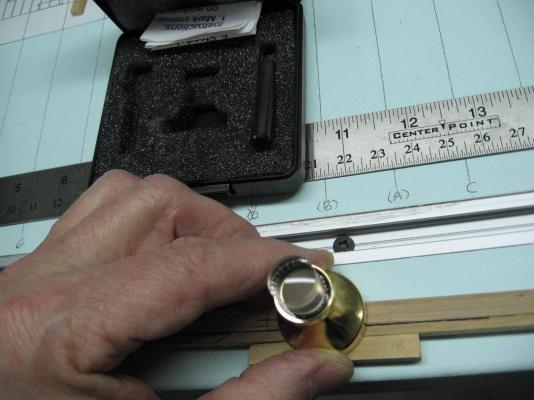
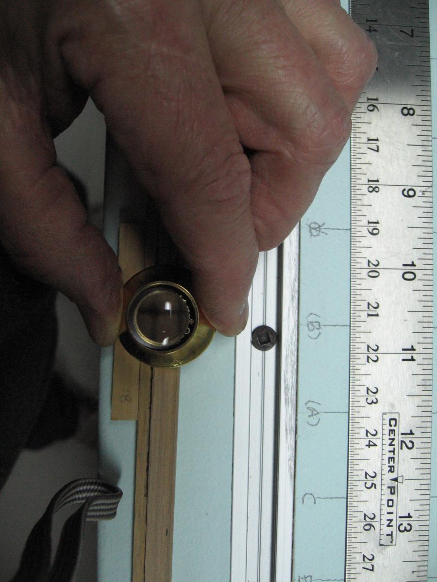
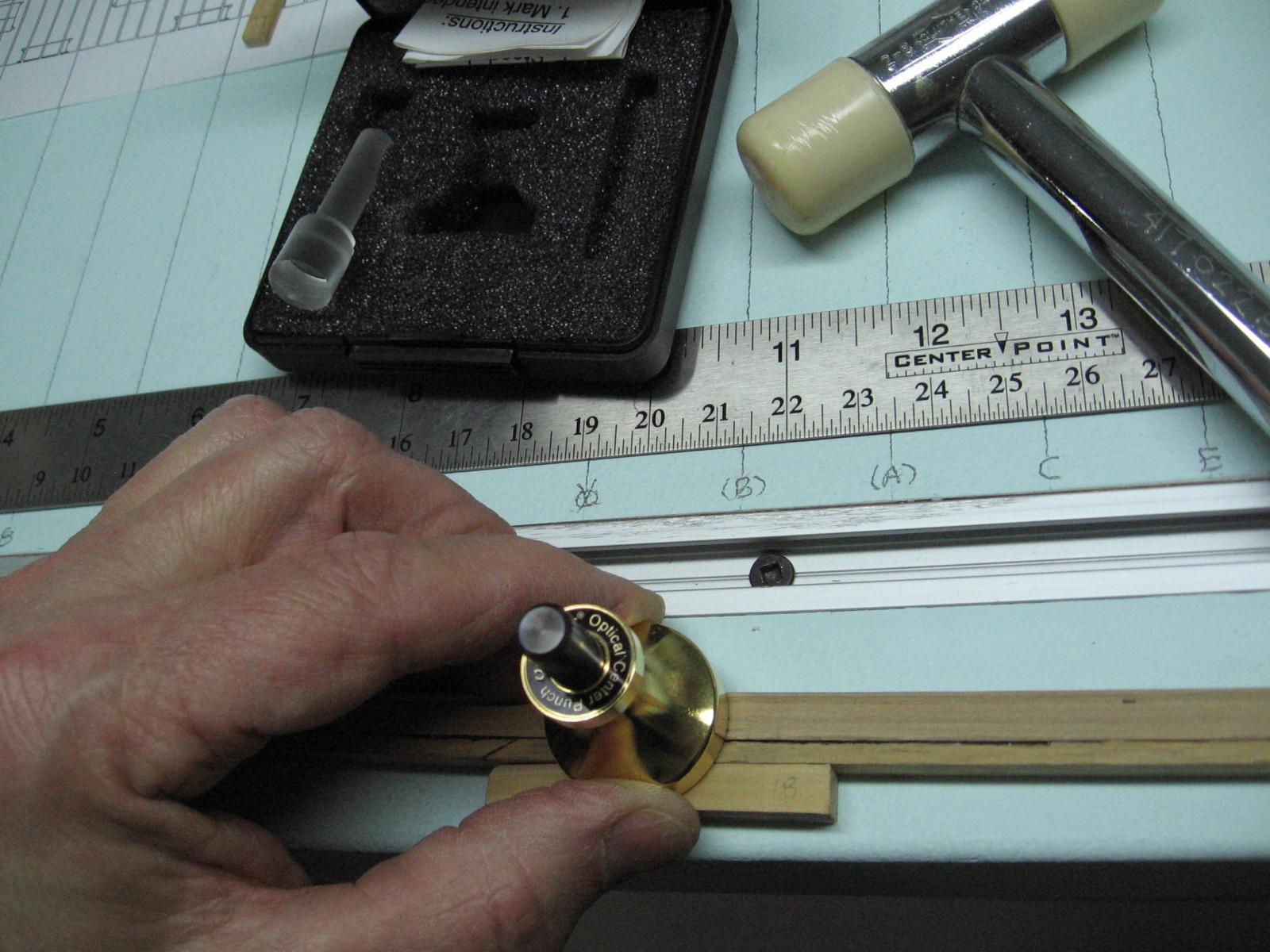
Marked the bolt hole locations in the keel scarph joints. Made a paper template and used my scratch awl to dimple the marks through... looked awful. Filled that in with wood glue and sawdust and tried again with a pin. Still awful. Made a metal template and tried again. Still awful. I have a centering tool but hadn't used it as the punch is pretty large. Possibly if tapped lightly it would be okay, it worked. Insert the magnifying cross hair piece to line it up to the mark, remove that and insert the punch and give it a wee little love tap.... repeat... they look great. Alignment is perfect. Marked all these bolt hole locations.


I knew all was going to well.
The keel that was straight all week is now warped!!!! Lifted up almost 3/8" (1cm).
How did this happen?
Any ideas what I should do now?I cannot soak it as the false keel will unglue.
I've presently have it set up with weights and am attempting to counter bend it.
Any ideas?
-
These are the frames and their width dimension fore and aft (as opposed to the molded dimension ... inwards or athwartships) is determined by the room and space specification for that particular frame station. It can be different along the length of the ship.
Look at how smart I seem
 ... don't be fooled
  ... I just learnt this a while ago.
-
I think the "bubbles" are the tiny pockets in the grain of the wood.
You have to use a less powerful camera to not expose this

-
Thank you for the idea Druxey
I spent 29 years designing heat treat furnace lines.
We called the process Annealing.... I coined the term "O'Neilling"
There is also one file tucked away in a cabinet that was labelled INSTRUCTION MANUAL that after some period of time and frustration I crossed out the IN in red and relabelled it DE
INSTRUCTION MANUAL.I'll have to see if I have a well used and due to be retired blade in the shop.
Otherwise it is back to the left over ceiling tile support frame.
-
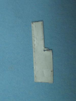
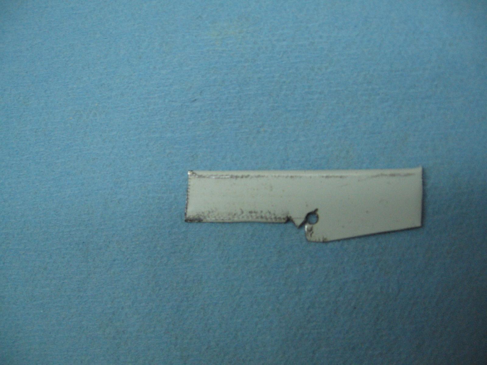
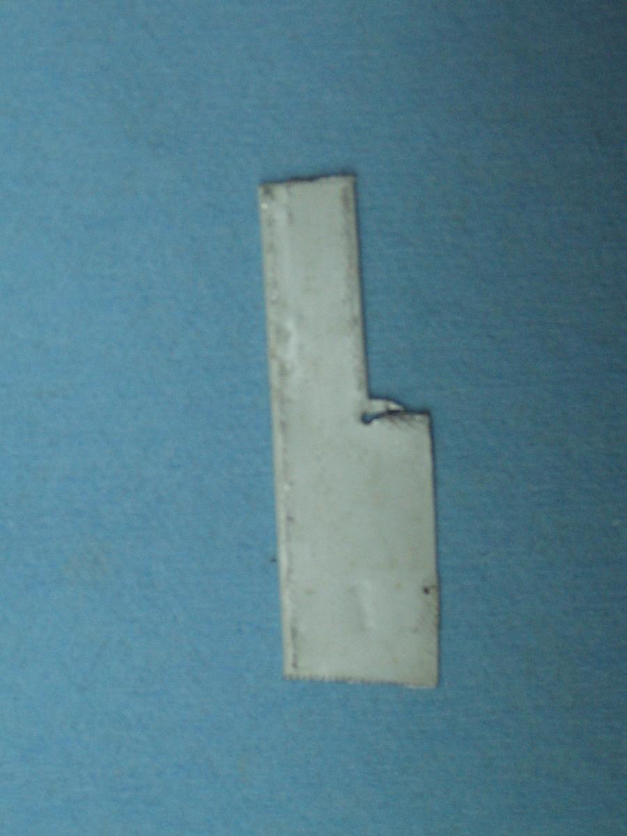
So I slept on it.
As it took a whole half hour to make my first ever scraper I've decided to make a second scraper.
I will get the notch higher on the keel. nearer the top.
I'll first make a larger corner relief hole, possibly 1/8" diameter.
Then I will scribe my reference lines so the hole will be further back.
The flaps will be cut after that and folded over... these worked well at not scraping the surface they dragged against.
We'll see if I have the energy when I get home from work tonight.
-
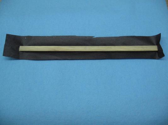
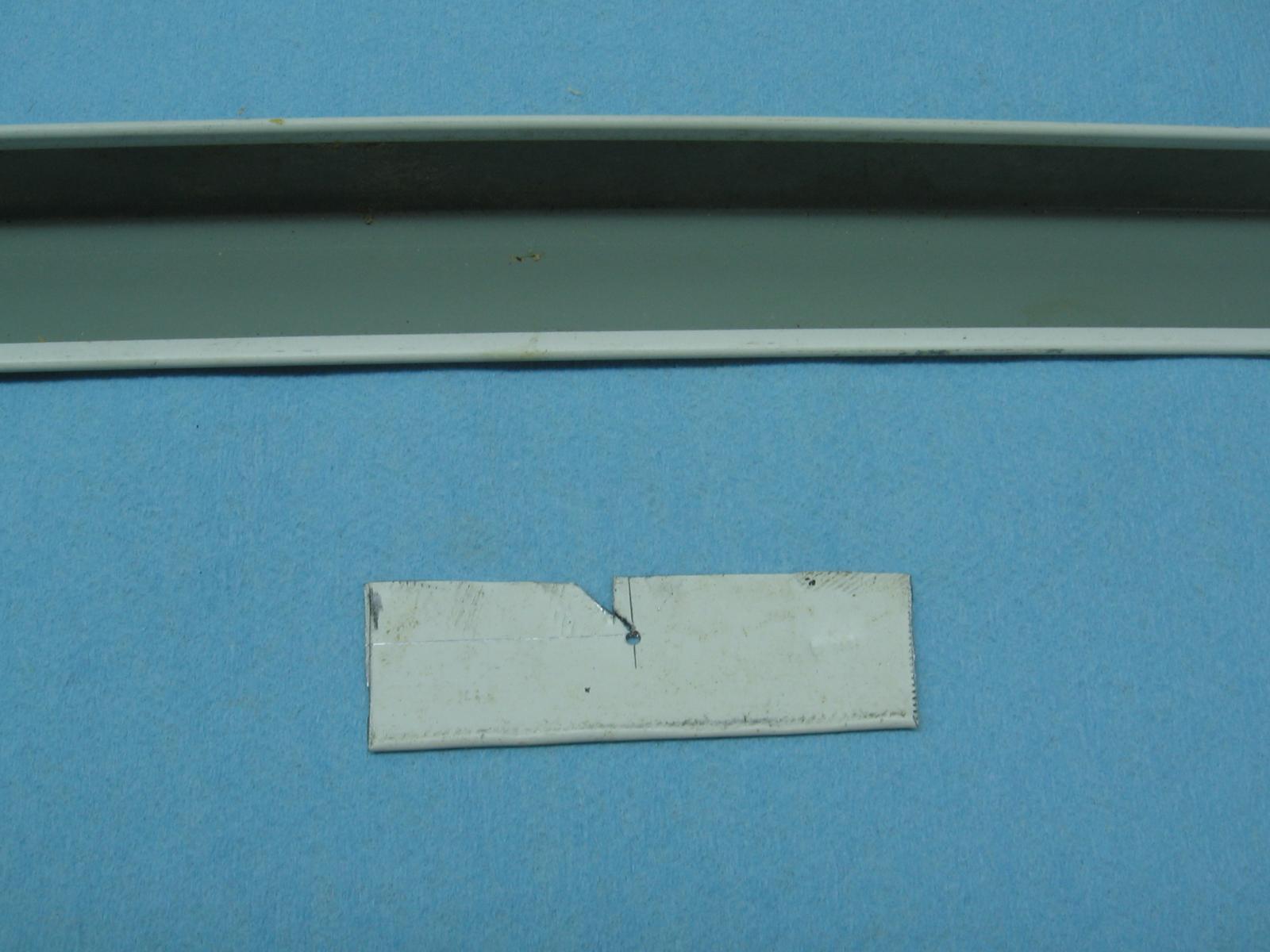
Completed my first attempt at a keel rabbet V-notch scraper.
I used a piece of a left over ceiling tile perimeter L support frame.
Laid out the keel side and top surface lines.
Marked of the 4" thickness of the planks = thickness of the notch (OMG it is tiny)
Punched and drilled a 1/16" diameter hole slightly off centre, more so inboard then outboard.
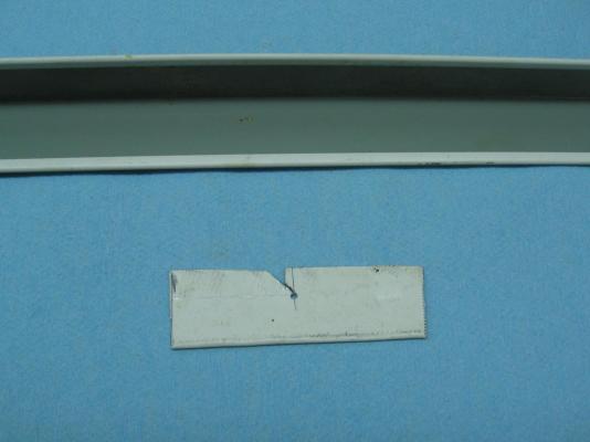
I folded over the tabs so a soft edge would contact both the top and side of the keel.
Rough cut the V cutting edge with some tin snips, filed one side and ground down the other with my dremel.
It took about 15 or so passes to get a good deep notch and it doesn't look half bad!
The notch should be closer to the top of the keel... I guess I was a little too heavy with the dremel.
I might try a spacer to pull the notch closer or make a new scraper.
I'll need to sleep on this.
- AnobiumPunctatum, tadheus, ggrieco and 7 others
-
 10
10
-
Saturday 19 March 2016
Once again had to wait until the weekend to work on my build.
Started off with an unrelated disaster in the bathroom shower plumbing first thing in the morning which delayed progress further... but on the up side (thanks to Google search and videos) I now know how to extract the glued end of an ABS pipe out of a shower drain plumbing socket.
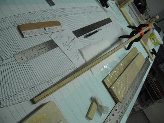
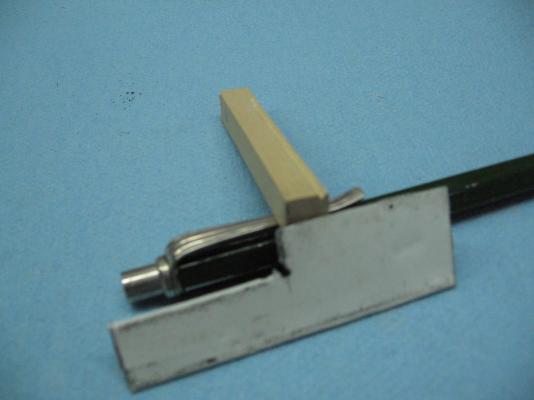
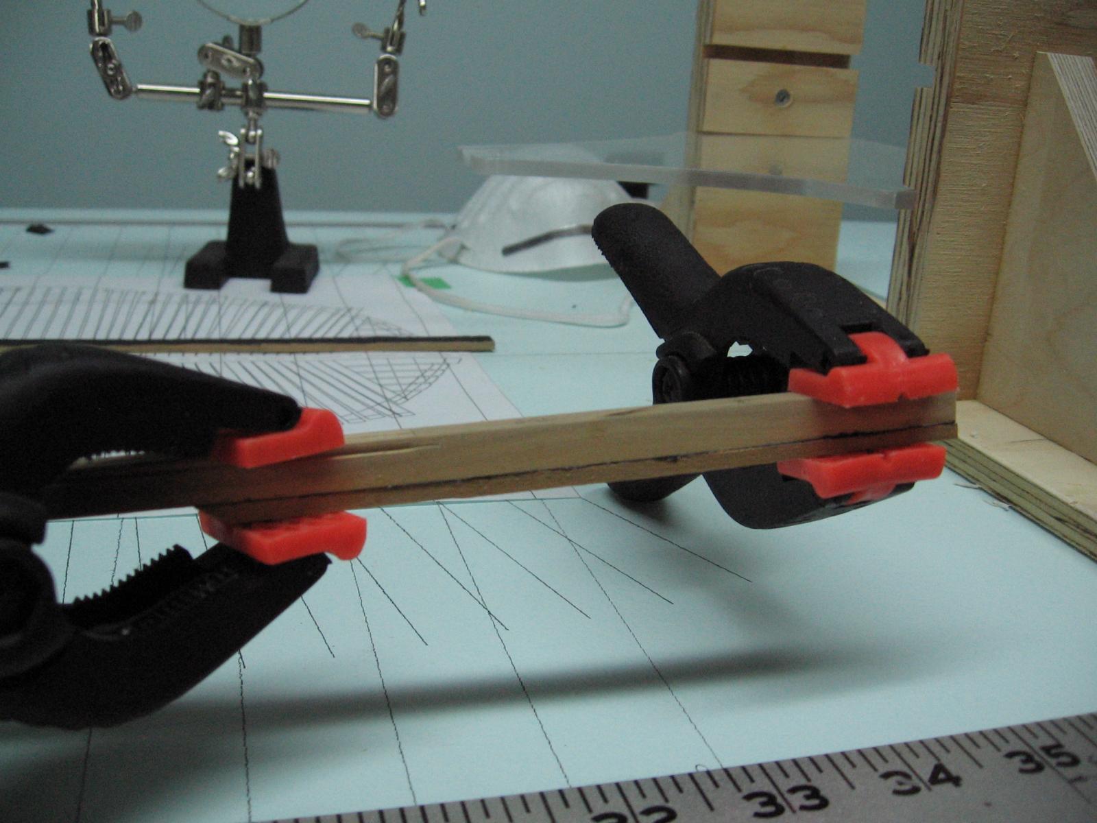
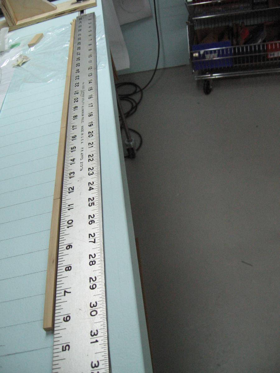
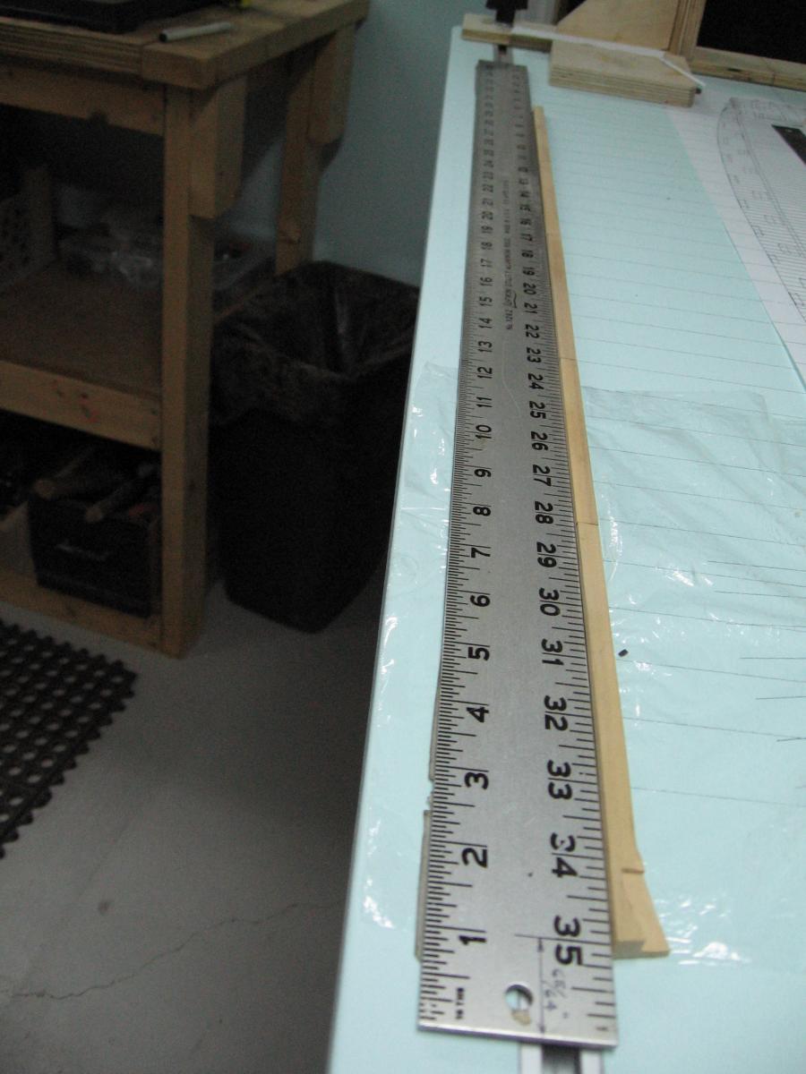
Seems the third try was the charm with the 18" square keel. I assembled the pieces and I am very happy with it this time.

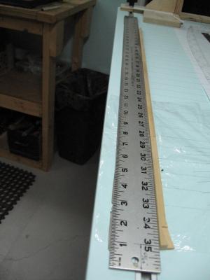
You can see I still utilized my metal straight edged scale as an aid to keep everything as near perfect as I might.
On closer inspection I noticed the foam backing on my scale bulged out and nudged the keel sections out of alignment so I trimmed this back a bit. I did not clamp it to edge of the metal scale this time. I used finger pressure and held it for a few minutes.
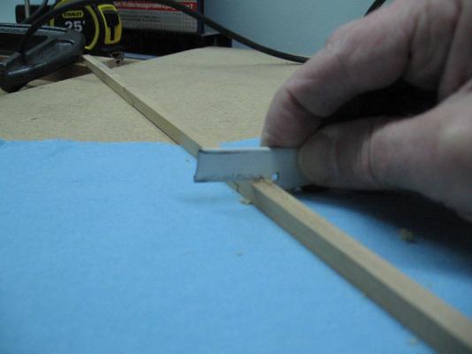
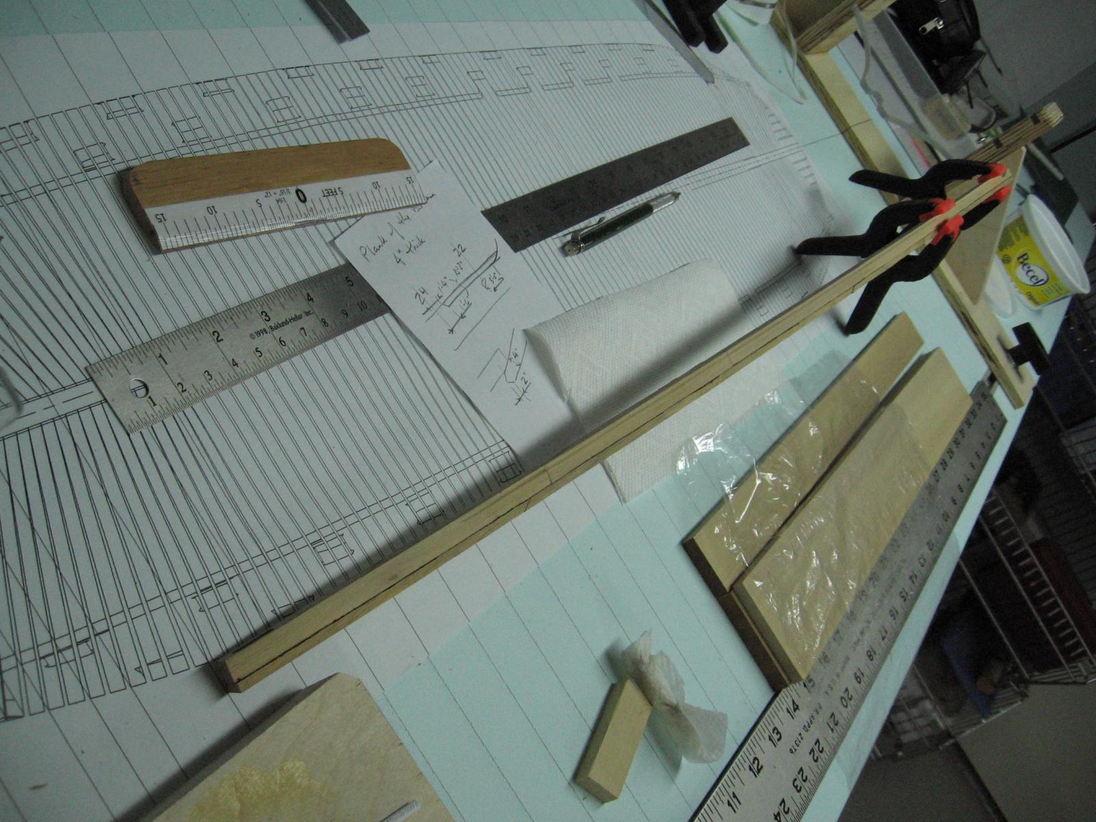
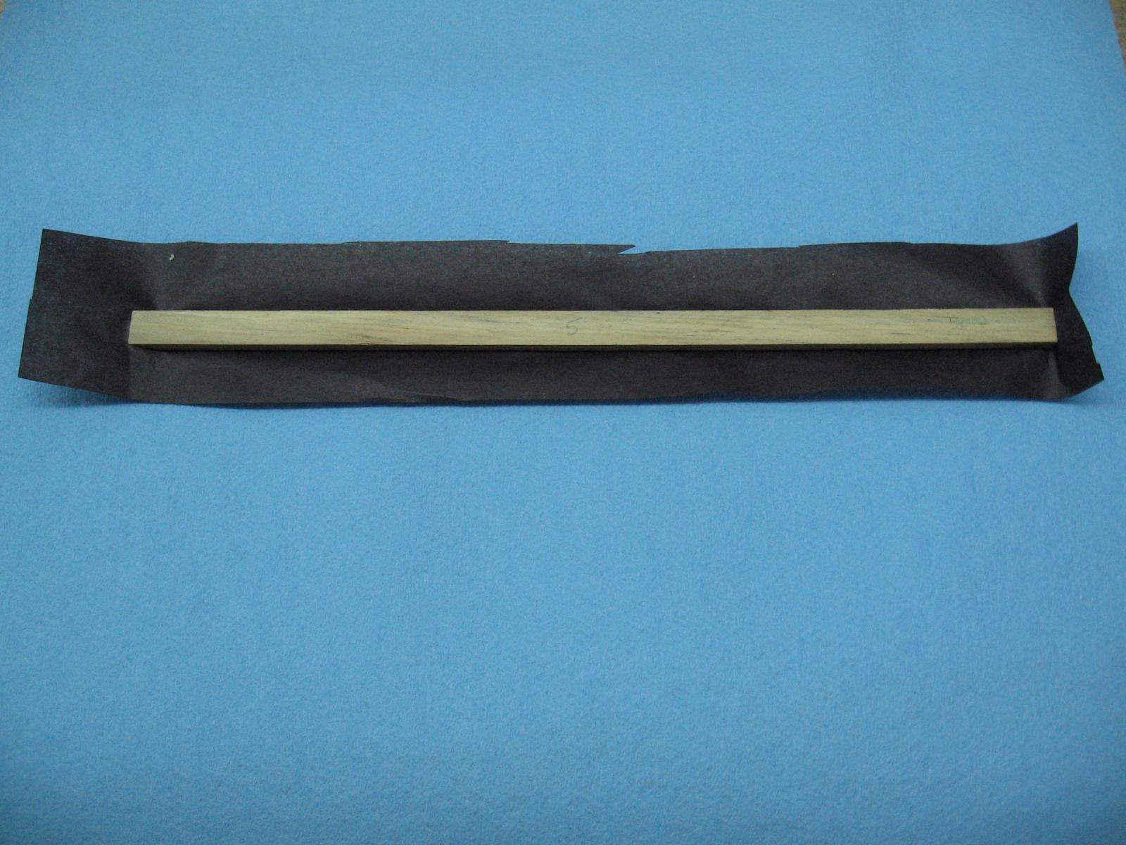
I also made the 7" thick false keel sections and wood glued the "tar and hair" black tissue paper to the top side of the pieces. The false keel is made from my eastern hemlock (fir).
I found a #10 scalpel blade works best for trimming the excess.
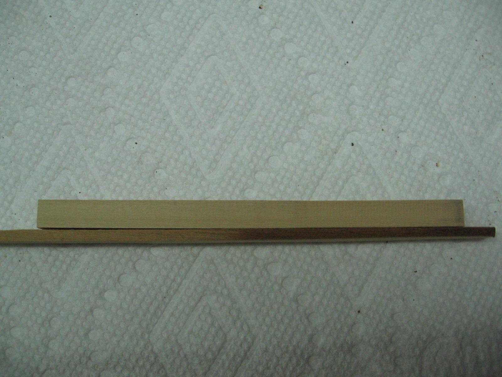
At first I thought I might stain it to make it stand out more but when I did a test I saw the hemlock is naturally a shade darker than the boxwood and looks appropriate without stain.
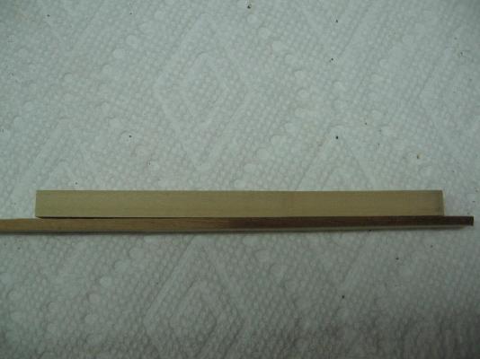
The boxwood is above and the hemlock is below. The left side of the hemlock is natural and the right side is lightly stained.
I hope to mark off and scrape out the rabbet line in the keel today then bolt the scarph joints of the keel sections. The next step will be to wood glue the false keel to the keel, and nail and staple it.
We shall see how far I get
-
I have just heard back from NMM regarding the stealer top timber "Waldo" and post a small portion of the response from Nick Ball, Assistant Curator of Ship Models.
"...I would probably call it a ‘filler top timber’, but not sure if this term is really correct, as a filling frame is actually any single frame spanning the breadth of the hull, as opposed to a double frame, i.e. two frames joined together which span the breadth of the hull."
The message continues with multiple examples of this occurring.
Now I am torn... stealer or filler... or more affectionately: Waldo?
-
-
-
-
Hoping someone knows the answer.
I just seems to me treenailing (dowels) would be easier to drive home from one side only
but the contract specifies bolts and I cannot imagine how
Last century rivets had to be red hot to hammer the heads to a tight mushroom shape (bridge construction) so I imagine it was the same in the 1700s (for ships)
How could they pre-insert a red hot bolt, get the timber in place, and then hammer the end over before it was too cool and still support the inaccessible far side head of the bolt.
Stuff like this keeps me awake a night

- robin b, CaptainSteve, mtaylor and 2 others
-
5
-
It is a monotonous job but the finished effect is tremendous!
-
-
-
Thank you all for your help.
Here is the exact wording...
[Page 4]
FRAME --- It being of the utmoft confequence to the strength of the ship, that all the timbers of the frame should be as much as poffible be preferved from being cut by the ports of each deck, a difpofition for that purpofe is made on the faid draught, and as a further means to obtain it, the faid timbers appointed to make the sides of the ports being continued up to the top of the side, are to be framed in bends, 1st, 2d, 3d and 4th futtocks and top timbers together (as diftinguifhed on the draught) and faftened with three bolts of 1-1/4 inches in each scarph, and that the firft futtocks be bolted to the refpective floors of every bend, with 3 bolts of 1-1/4 inch diameter, that the stations of the faid frames fo diftinguifhed, are to be preferved with great exactnefs, and fo fuch of them as ftands afore and abaft the square frames, and are to be canted, thefe alfo are to keep their stations, at the breadth, and what is required to give the fafhion piece and beakhead timbers a proper flight, or cant,.... (continues) -
-
My build contract states "... are to be framed in bends, 1st, 2nd, 3rd, 4th futtocks and top timbers together, and fastened with three bolts of 1-1/4" diameter in each scarph..."
Was there a pattern for laying these groups of three out... possibly diagonally over the length of the scarph (height of the frame)?
Anything I find shows two laid out diagonally but there is no source to suggest this is correct
FYI:
Floor timbers are sided 13-1/2" to 16"
Top timbers are sided 10-1/2"
Futtocks would be anything from 16" to 10-1/2"
Futtock heads and heels are joined with chocks whereas top timbers employ a plain scarph.
-
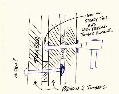
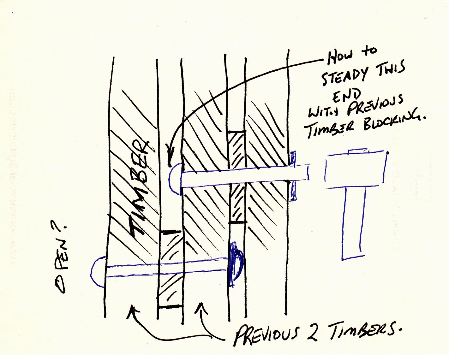
Okay
So the very first set are easy to do.
Then a third frame goes up....
Presumably the hole was bored through the second and third frame, and the bolt installed in the second frame, before it went up as the bolt could not be installed after.
How do they brace the bolt head to hammer the other end?
Did they use metal plates and wedge shims in the space?
-
Framing filler pieces
Construction of the English Man of War 1650-1850 by Peter Goodwin, pg 17 states:
"The filling pieces were made ..... and were bolted in place in the fore and aft direction."
As bolts were more like iron rivets with a ring washer how did they hold the one end in while hammering the other end to mushroom it over the ring? Particularly when the space was 1/4" or 1- 3/4" or even 2-3/4".
Did they insert a temporary metal filler to hold the bolt in place?


Dunbrody by Mahuna - FINISHED - 1:48 - Cross-Section - Irish Famine Ship
in - Build logs for subjects built 1801 - 1850
Posted
I believe The Seventy-Four Gun Ship by Jean Boudriot, Volume 1 of 4, Hull Construction, pages 102 through 106 of 131 is a very good reference of the French construction.