


AON
-
Posts
2,592 -
Joined
-
Last visited
Content Type
Profiles
Forums
Gallery
Events
Posts posted by AON
-
-
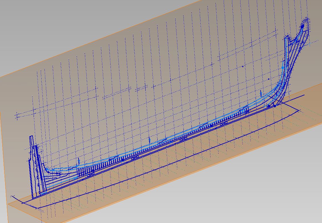
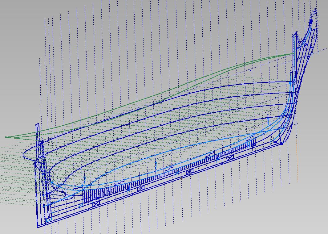
Well I completed the hull shaping at each station line.
Have to complete the stern transom shaping.
I think I will draw the frames, and this time extrude between them (rather than lofting), then slice and dice into individual frames to make my templates... which was were I was before the crash.
Almost there.
and btw
July the first.... Happy Canada Day, eh!
-
shaping the hull at the station lines
going much quicker than the first time
and the line work is much cleaner
It pays to work smarter... but learning to work smarter means you have to learn in the first place
So my computer crash was an opportunity after all.
-
-
This will sound easier than it is...
Practice on two or four scrap pieces first.
Take all your pieces (top and bottom) and use CA glue (a very extremely small dab) at a similar corner at both ends and secure them to a base board, side by side, in line, solder style to look like one solid piece,
Let this cure.
Mark off the thickness of the pieces with a very sharp pointed soft HB pencil and a 90° square perpendicular (across) to the joints
Cut into the pieces (straight down, light cuts) with a sharp thin blade (exacto) knife to not more than half the thickness of the pieces following the lines
Chisel out the notch making light diagonal cuts
Fold some sand paper and using the edge sand out the humps... or use the edge of a nail file if it will work
Use rubbing alcohol on a cotton ball to wet the glued ends of the wood, let this soak in for some time to free the glued ends. Do not force the pieces apart however tempting this may seem. The rubbing alcohol will dissolve the glue and you should be able to twist them off.
Dry fit the notched pieces together
If they look reasonably good glue them together to make your rough grating
Very lightly sand top and bottom sides to be flush and you are done
There is no better feeling then having done it yourself!
-
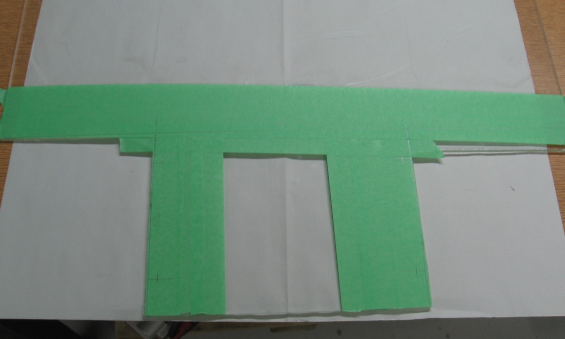
Are your gratings finished or dry fitted?
I ask because I believe they should be set into each other (like egg crating or those divider cardboard sheets between bottles at the liquor store) so the top side and underside are flush.
-
-
Thank you Druxey
The new approach I've taken has also made quite an impact
Christian, the first go around was with SolidWorks. This time I am using AutoDesk Inventor. The programs are similar but different enough to give my brain a workout.
-
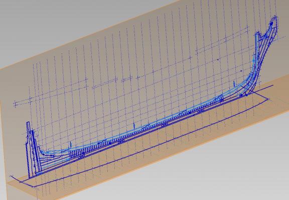
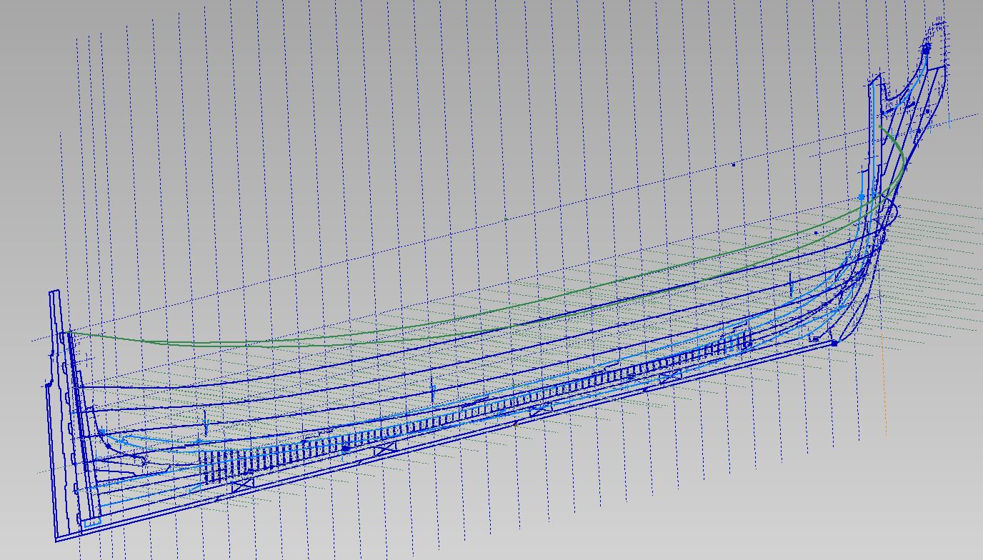
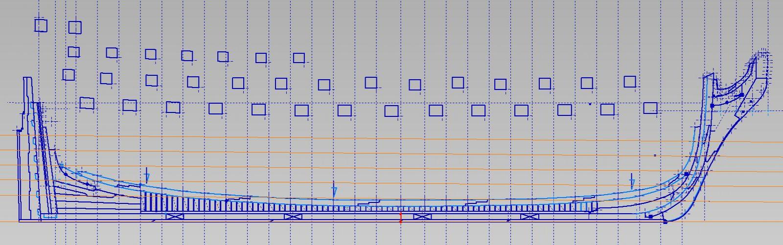
Managed to get a good start at the top timber line 2D layouts
you can see both in the image below
yet to fine tune (extend) the side view (sheer) so they are presently construction line until done
Since we will be having a wonderfully stormy weekend I suppose I might get it done tomorrow (???)
-
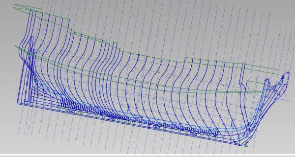
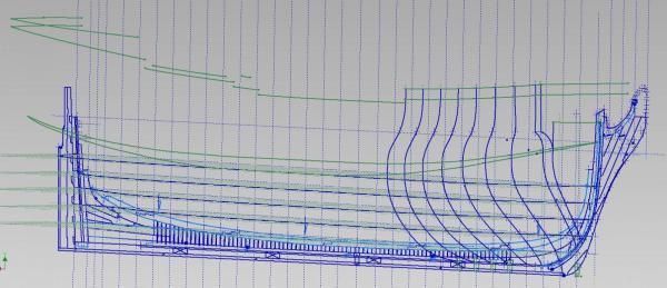
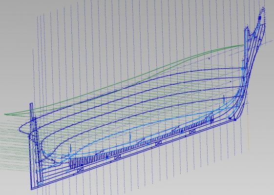
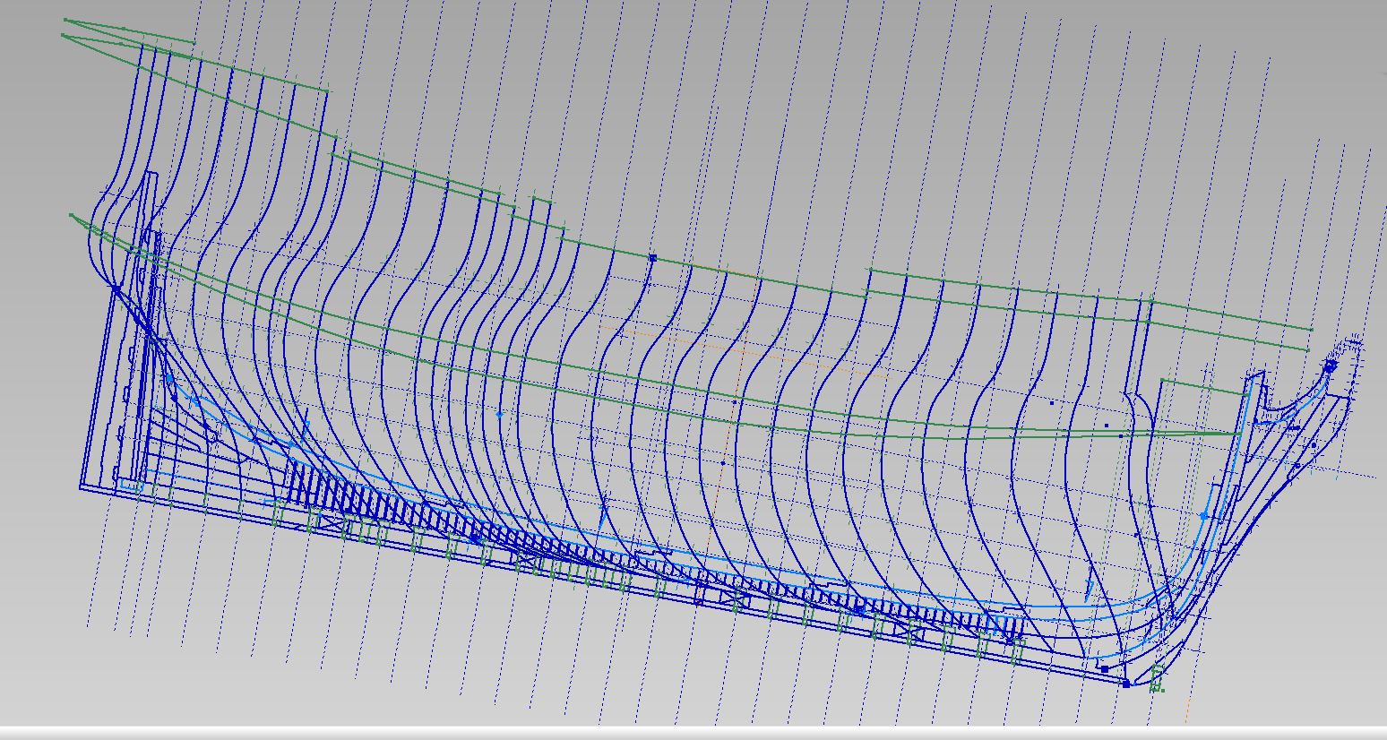
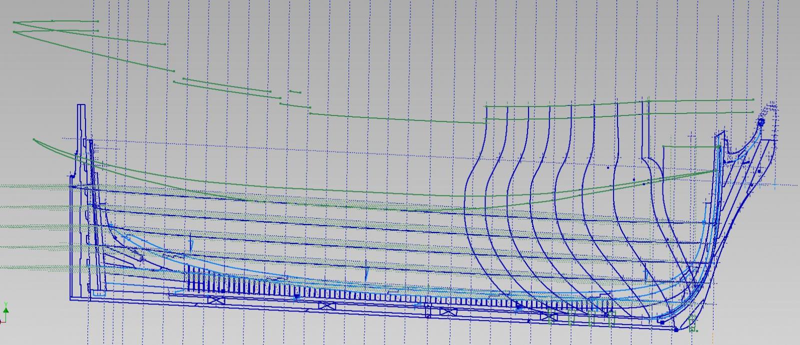
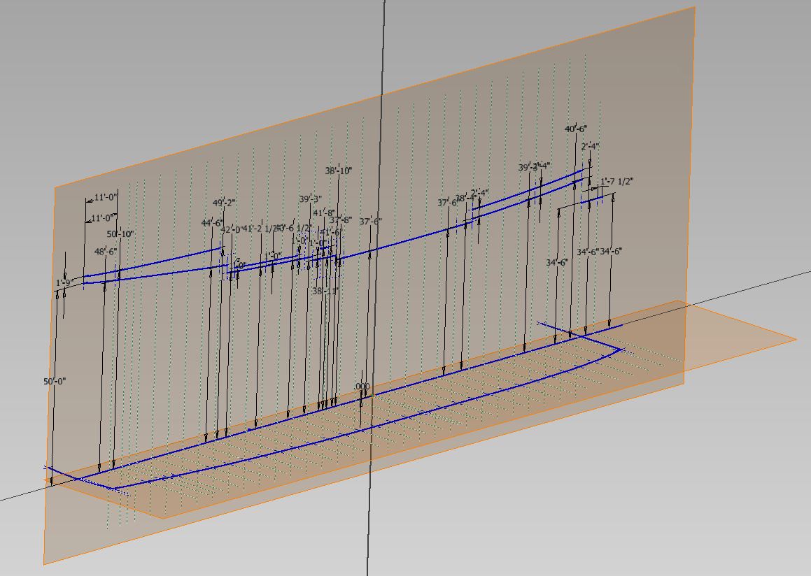
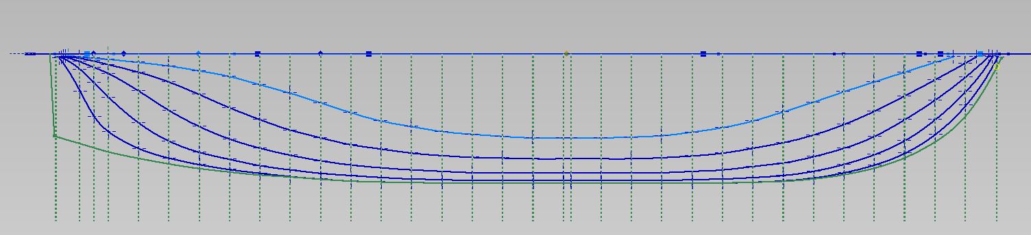
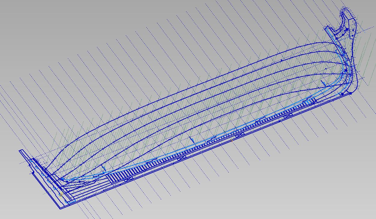
Well I managed to get my Upper and Lower Breadth Lines drawn
I plotted them on the Breadth Plan (bottom 2d view) and then again at elevation on the Sheer Plan (2d side view) and finally projected them to a 3D line from those two views (the green lines)
One step closer to drawing the frames (again)
First I must draw the top timber lines.

-
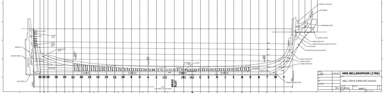
I had some feed back on my layout... I chewed over the suggestions a bit and looked at some other plans and models. as recommended.
Of course most of what you want to see on models are covered up in the photos.
Images don't seem to ever show that one detail you want or when they do it disagrees with both what you did and what helpful people are suggesting.In the end I made some changes to the pieces that comprise the bow assembly and the rising/dead wood and its connection forward and aft.
Thank you for the help.
EDIT NOTE: dwg removed and update posted 15 NOV 2015
-
-
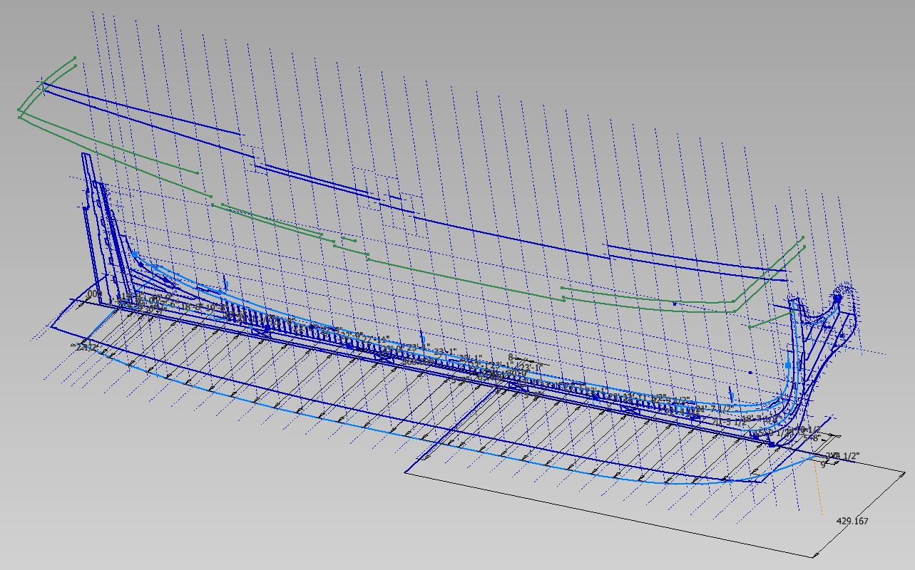
So I've completed the first template drawing and will be getting it printed out this week

I have labelled the pieces to help me remember the names.
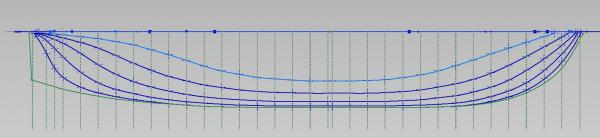
I have also sketched the five waterlines at elevation.

This was done differently from the first go around.
The first time I had plotted it out all on one level, having sketched each section line as painstakingly measured from the Body Plan.
Then I compared the two by inspection from the top view... they were quite different.
This time I intend to use them directly in the shaping of the station templates.
I also relaxed my measuring... using my trusty triangular scale with 1/4" = 1'-0" scale on it
I can comfortably read to within a 1/2"
I am getting into the tough part now... how to plot the upper and lower breadth line in 3D (everything else has been 2D).
I won't bore anyone with the steps (as I am not quite sure of them myself yet)
But I hope this version will be simpler and quicker.
So far so good.
- harvey1847, Don9of11, hexnut and 3 others
-
 6
6
-
My ceiling of my original (less than half size) work shop was unfinished and was fine... I was quite content.
The new expanded workshop has drop ceiling tiles as I mentioned earlier and it makes the room much brighter and a very much happier place, honestly.
I couldn't believe the difference and would never go back
-
My workshop is in the basement.
It was an unfinished area.
New wiring, insulation, vapour barrier, drywall, painting walls and floor a light bright colour, lighting, heating/cooling ducting over head, drop in ceiling tiles (I doubled up on mine in an attempt at noise abatement to the upstairs)
I am always concerned with finishing a basement and then having flooding issues or outer concrete walls cracking and water finding its way to the insulation and floor.
To me a basement is a basement.... but others seem to be living in theirs!
-
-
I am very happy others find this useful or at the very least interesting.
Druxey, mine is a basement shop with no outside windows. Lighting is florescent and overhead... which doesn't work well for a fellow with a fused neck. Everything else is too bright (or I am just getting too old and picky).
I think this light table... I've decided it is a light table... will do very nicely.
Thank you to Greg and his volume in the TFFM books!
-
-
-
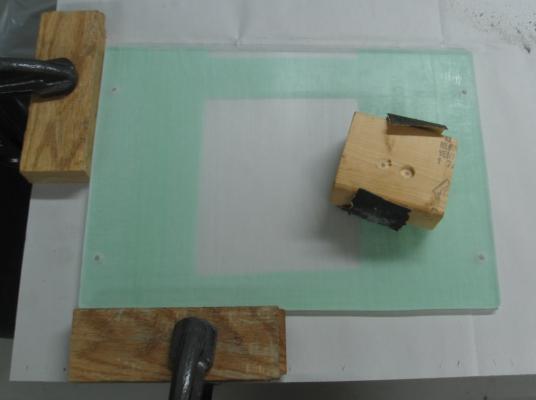
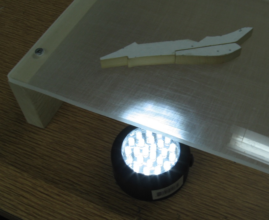
Today I made a light Box... or more correctly a light stand?
I read in TFFM that Greg uses a light box to inspect, mark and fine tune his joinery.
If it works for him I'm hoping it will help me.
This little project cost me next to nothing as I used scraps.
I taped, measured and laid out my cut lines and hole locations on the sheet of Plexiglas and onto the tape with a pencil.
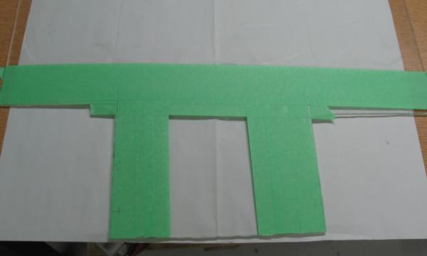
Then I clamped the plexiglas down to my table and using my scroll saw and a plexiglas cutting blade I made my cuts. You have to keep the saw moving or the plexiglas overheats and gums up. I cut about 1/8 inch outside the line.
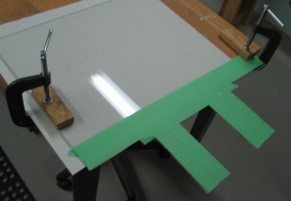
I then clamped the plexiglas in my vise and using a very rough file I filed the cut edges down to the pencil line.
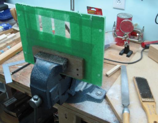
To diffuse the light shining from below I sanded the underside. Passed it quickly over my belt sanded. Quickly so it doesn't overheat and make a mess. Then I hand sanded in one direction with extremely rough sand paper. Finally I used 80 grit and sanded in four directions, one at a time. First up and down, then across at 90 degrees, and finally diagonally (corner to corner).
I drilled and counter drilled the plexiglas for the wood screws, cut two pieces of wood for the stands, marked off the screw holes using the plexiglas as the template and drilled pilot holes. Screwed it all together.
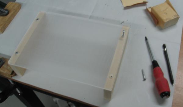
I slide a LED puck light underneath and that was it... she was ready to use.

You can see it seems to do a great job of highlighting the imperfections.
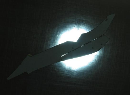
Hope someone else finds this idea useful!
-
-
-
-
-


HMS Bellerophon 1786 by AON – scale 1:64 – 74-gun 3rd Rate Man of War - Arrogant-Class
in - Build logs for subjects built 1751 - 1800
Posted
Thank you Don
presently having some issues appreciating how Inventor works with splines and mirroring
seems they may need to be constrained every which way !!! as when mirroring things go wonky.
Presently I am very frustrated with this program... it is the learning curve