


AON
-
Posts
2,772 -
Joined
-
Last visited
Content Type
Profiles
Forums
Gallery
Events
Posts posted by AON
-
-
Thank you Carl,
There are likely a number of other ways it could have been handle and I am open to hearing them all.
This is my first build since 1990-ish (second in my life) and is quite different from balsa wood and an exacto knife so I've a lot to learn.
I acknowledge my "novice" level and expect to make a considerable number of errors.
The learning curve is steep and I am a willing participant/student.
As I get further along and find more time (I plan to retire in two years) I may begin again as I find I progress from novice to advanced beginner to competent and hopefully someday proficient! I do not think I'll have 40 years to become an expert.
Then again as I progress I may quite like what I've accomplished and carry on.
Every day is a new beginning.
Please do continue to make suggestions.
-
I didn't do it before because I had to assemble the tiny bolts through the plates.
The blackening is an oxidation process and so I feared the almost size for size holes/pins might not assemble after the fact.
The "flange" or rolled edge created on the pins is tiny so the hole cannot be much more than it is or the pin will drop through.
I thought of assembling them off the wood but was concerned about getting 6 or 7 pins to they align with the pre-drilled holes in the wood.
If the pin went in wonky it wouldn't align.
I could have drilled the holes in the wood larger than needed but then the pins would be loose in them.
Could have put glue in the holes but 10 seconds is not a very long time to get it right.
So doing what I did and having read on the forum that it does not affect the wood I felt it was the correct method.
-
-
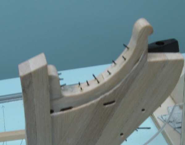
SEP 17 2016
Yesterday was a good day to work in the shop, raining all day with thunder later in the afternoon.
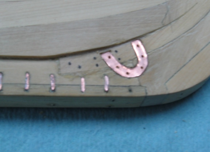
I worked on finishing the installation of the brackets and horseshoes.
First I had to make the bolts.
I followed the method posted elsewhere on the forum
( Making nail s with rounded nail heads
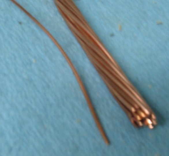
I managed to acquire a short length of multi strand wire with strands measuring 0.031" diameter (1.98" to scale).
The snipping created a burr that I tried to file off but what was left tended to help hold it in place.
The rolled head was very tiny and barely noticeable but it was round and for the scale looked very good.
I needed 26 bolts but made 30.
I cleaned everything in white vinegar, rinsed in water and dried with a paper towel.
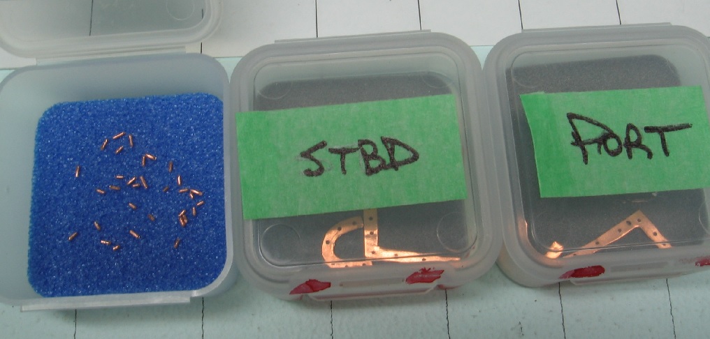
Separated everything in clearly marked containers so I wouldn't try to put the port bracket on the starboard side (as the relief are cut to match the bracket).
Wearing latex gloves the brackets and horseshoes were glued in place using Gorilla Glue (10 seconds time to work).
Getting the bolts assembled with tweezers and my smallest hammer was a real treat.
I mixed up a weaker batch of blackening agent and used a cotton swab to apply.
Then, of course, disaster.
Some glue must have seeped around an edge or through a bolt hole and the blackening was not over the whole assembly.
I then spent considerable time re-cleaning in place and re blackening.
The final outcome is not what I'd hoped for but it is not completely terrible (or am I trying to convince myself?).
I've thought (all night) of removing them but any second item will not fit perfectly into the existing recesses and bolt holes will not align.
I am going to have to stare at it a bit and decide if I can live with this, my second attempt at blackening.

-
The image explains the post.

- druxey, Omega1234, GrantGoodale and 1 other
-
 4
4
-
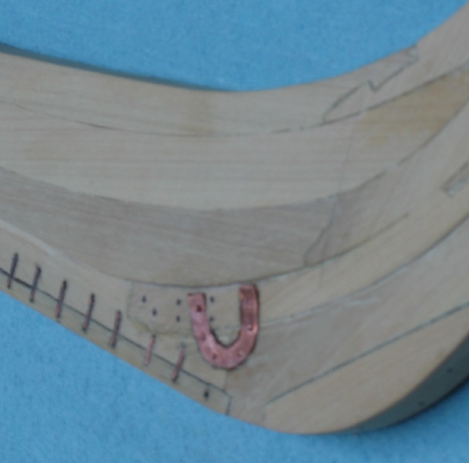
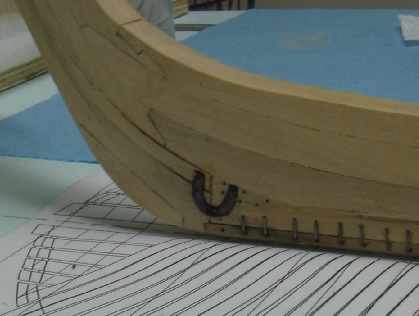
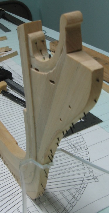
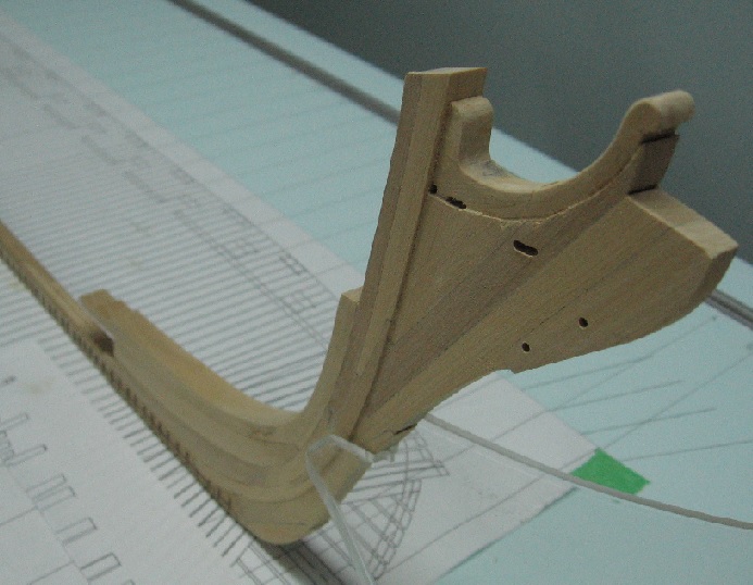
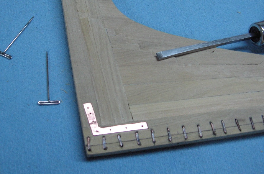
Cut the recesses for the brackets and horseshoes.
The brackets set just above the staples left a sliver of wood at the top.
I pinned these but still had to hold them down with my thumb to scribe along the edge with a scalpel.
I then removed the bracket and followed the cut line with a carving knife to get it deeper.
I used a mini chisel to remove the material and needed to wear my magnifying headpiece to see what I was doing otherwise it would have been much worse.
My eyesight is not what is used to be and is just getting worse.
I couldn't pin the horseshoe as the pins would have been in the way of scribing and holding with my thumb... ended up tracing the outline with a pencil and then scribing with the scalpel and knife just inside the line as best as I could. I also had to remove the fore most staple as it would have been under the horseshoe. I will reinstall these after they get shortened a wee bit.
I am happy with the outcome.
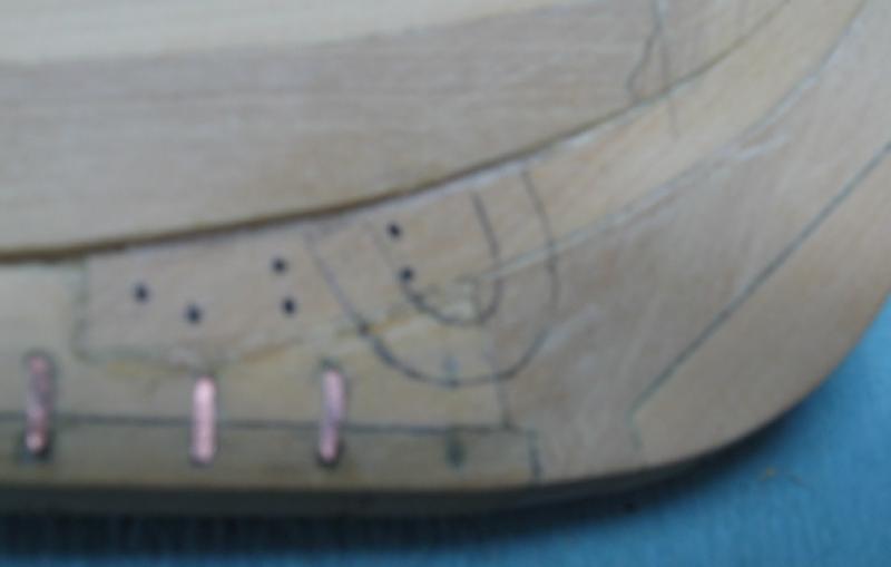
I marked the pockets and the back side of each piece with coloured markers so I know which goes where as they are not identical... just like the real build would have been.
I may install these and blacken them in place using a much weaker solution than the first time I tried with the staples.
-
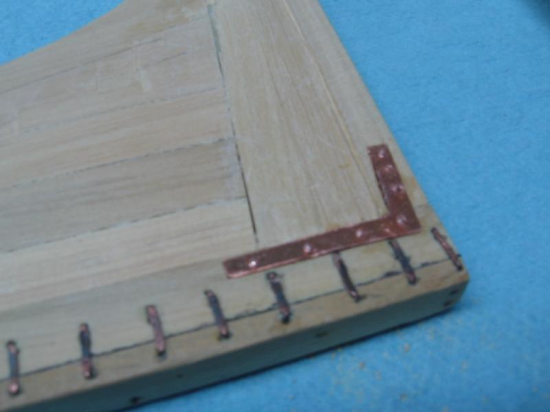
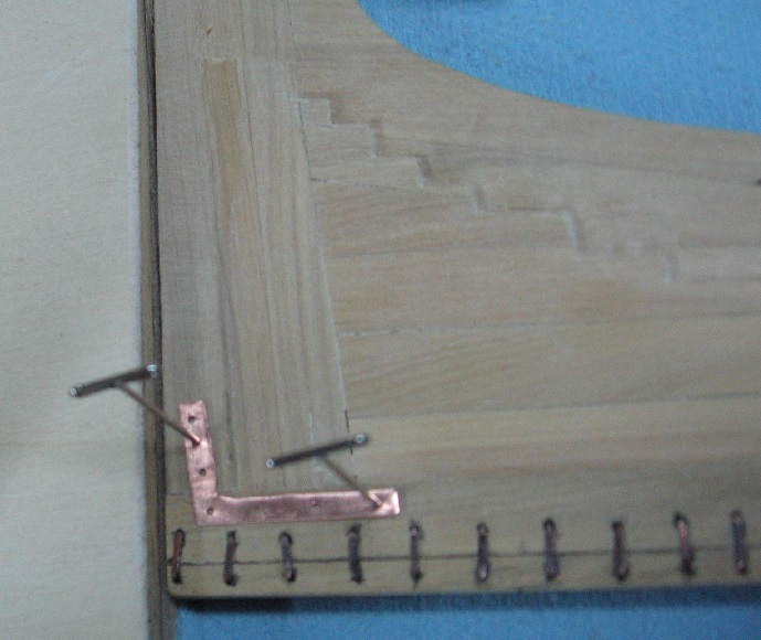
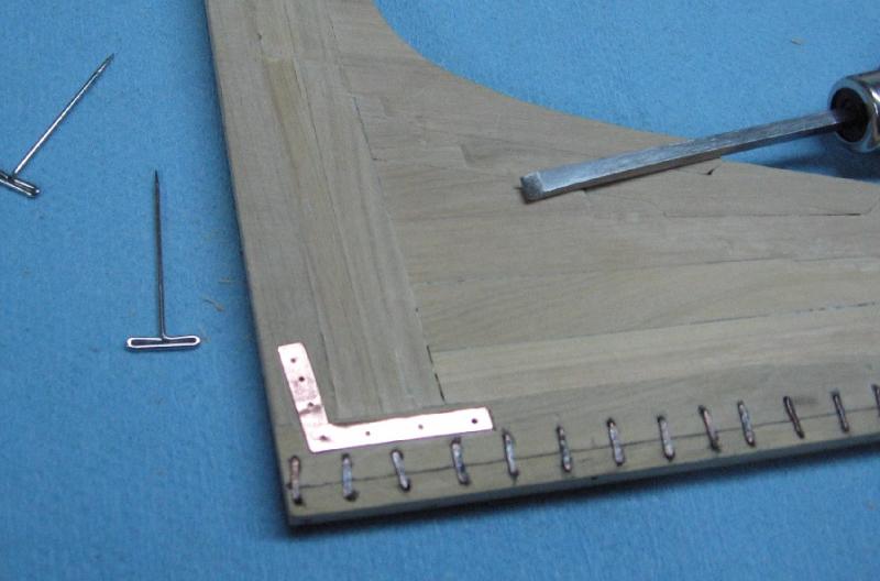
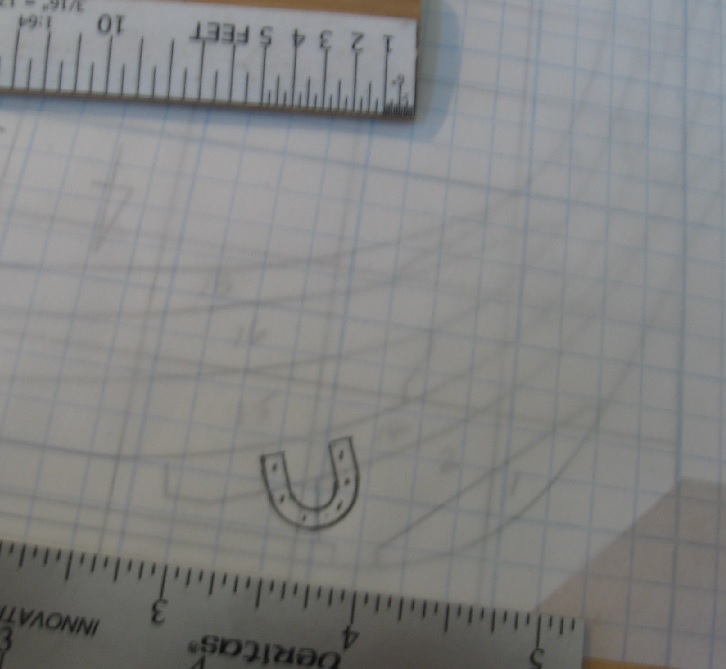
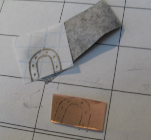
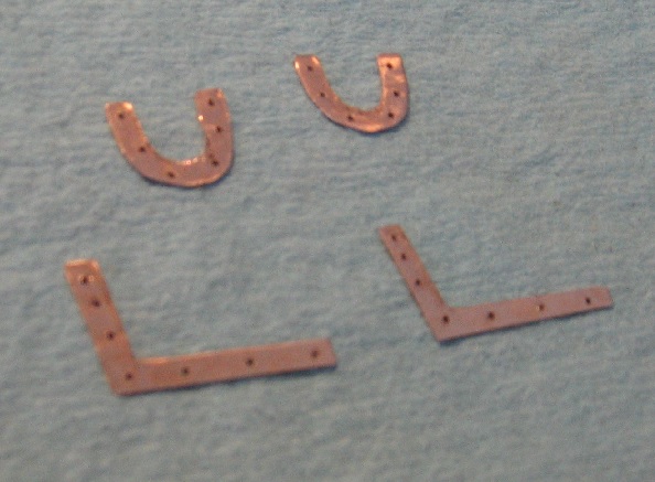
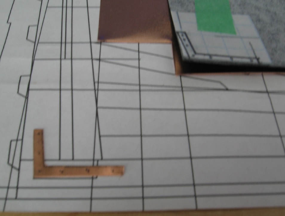
Got the stem horseshoe brackets and stern knee plates made.
I used 30 gauge copper plate (10 mil = 0.010" thick) which is 0.64" or practically exactly the 5/8" thickness required at scale.
I drew the shapes onto translucent graph paper then transfered the sketch to the plate with carbon paper.
The knee plate is 4-3/4" wide with horizontal leg at 5'-6" and vertical leg at 3'-6"
4 x 7/8" holes horizontally and 3x7/8" hole vertically.
The horseshoe was sketched to suit the space with the graph paper over the scale layout sheet.
I kept the shoe width at 4-3/4" (as best as I could).
Cutting with scissors was easy... except the curves on the horseshoe. I had to file these to finish a bit better after cutting.
The plate curls quite readily which makes it difficult to hold onto and the corners were sharp! I've chamfered them a bit.
The drops from the brackets were perfect sized for the horseshoe so they was very little waste.
The holes were drilled very slowly with a pin vise and small #70 drill bit.
These will be installed after I trim the bolts done earlier today.

-
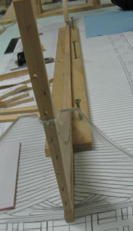
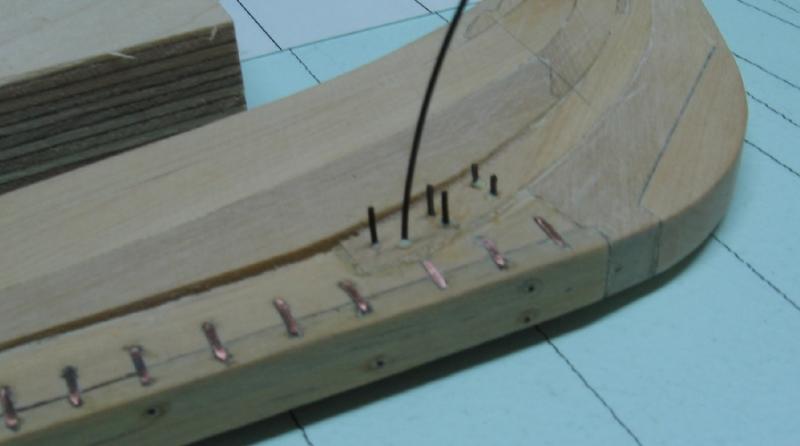
Sept 10 2016
Drilled and glued fishing line into the aft face of the Outer Stern Post, top face of the Gammon Piece and Extension, and forward face of the Stem Post assembly to simulate bolts. Snapped two drill bits in the process... one is still in there. I will cut flush and sand once the glue has time to dry.
There are some references to some bolting but seems to always be side views so I used my common sense (and artistic modelling license) to lay them out. I'm using yellow wood glue and I've roughened the line with sand paper to allow the glue to grip and hold.
Next is the horse shoes and knee plates.
- aviaamator, WackoWolf, gjdale and 13 others
-
16
-
-
-
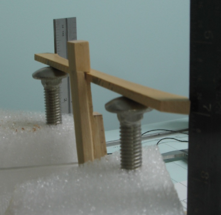
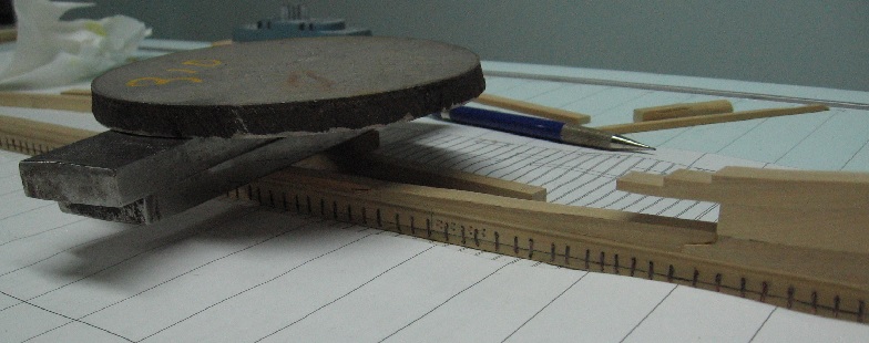
Devised a possible new easier method to set up the transom pieces.
I used a couple pieces of packing Styrofoam saved from some purchases (yes I am a pack rat)
Drilled a 0.3125 hole in for a 0.3665 OD carriage bolt
The snug fit allows me to move the bolt up and down while the Styrofoam holds it snugly.
I use my scaled squares to level it off.
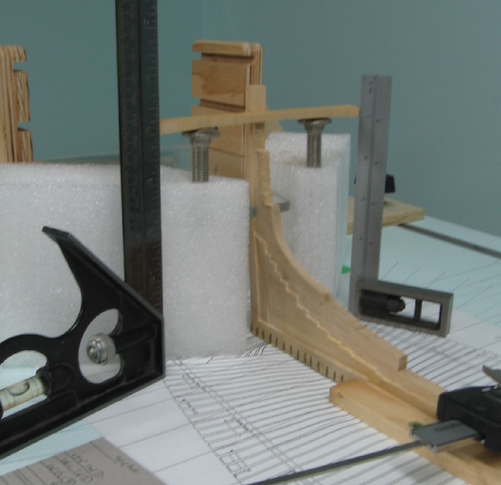
I also installed some bolts but need to research a bunch more.
-
Thank you for the comments Ed and I welcome all suggestions so don't hold back.
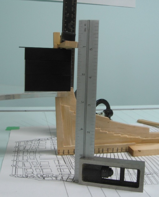
My table was levelled breadth ways with the lift mechanism and applying personal weight to one side so the bubble is close but you are correct, the smartest way is via measurement. I used my vernier depth gauge to setup and watch the bubble to assure it didn't shift. I originally tried setting up with a measured tick mark on cardboard but the vernier was less forgiving. As this top most transom piece (wing transom) sets at an angle I cannot put my shims under as I would like to but rather only the tip or edge makes contact. This is very time consuming and tipsy. I have been looking at David's fixture in TFFM volume 1 page 67 and may end up doing something more like it.... as Greg says in Vol 3 page 14: he has decades of ship modelling experience.
I also bought some pins and will be employing them as I've seen done by another skilled fellow here on the forum!
My 30 gauge copper sheets came in today. So I've quite a to do list to work on.
-
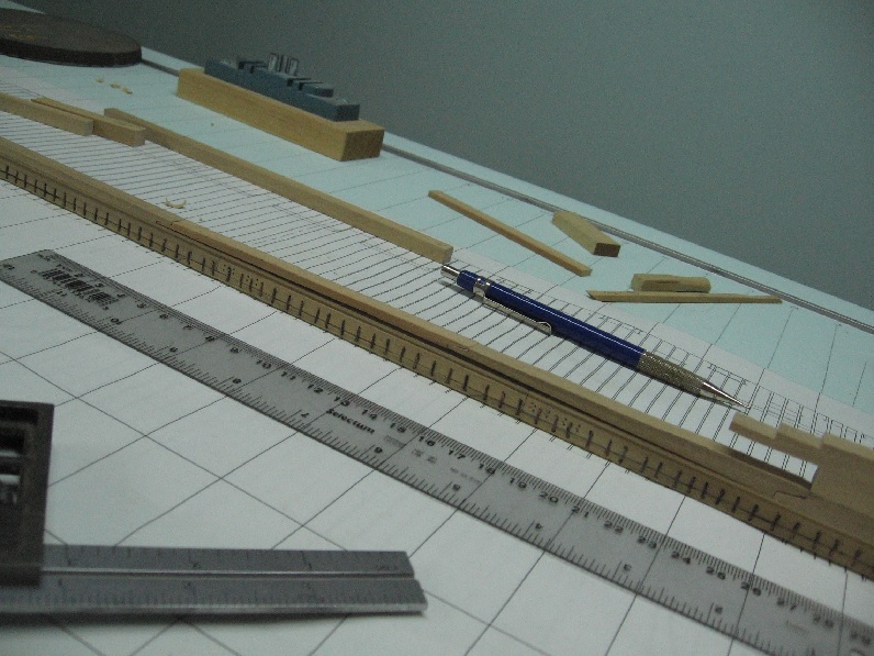
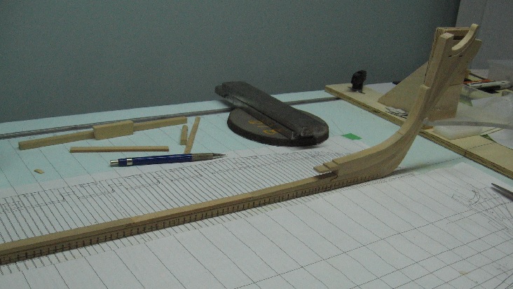
Sept 05 2016
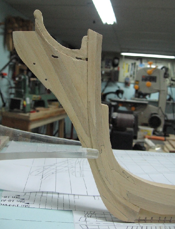
Completed sanding, relief cutting the stem and stern... and dry fitting the wing transom (to figure out how I might do it).
I need to add bolts to the stem post assembly and then add the horseshoe at the bow and the L (angle) bracket (knee plate) at the stern. Attempted to make these from wire (flattening and filing) but this didn't work very well for me.
I've ordered some gauge plate to use instead and expect it to arrive this week.... so the transom pieces should go up permanently next weekend.

-
Sept 03 2016
Installed the last two pieces of the Rising Wood.
Dry fitted into place (a tight fit)
glued and clamped
Done
I have to chisel in a few more reliefs in the aft deadwood and likely sand a bit more on the stem assembly before I fit the transom pieces that are already cut out as I won't be able to lay the assembly down on its side to do this work if the transom pieces are installed
- GrantGoodale, Canute, mtaylor and 9 others
-
12
-
-
-
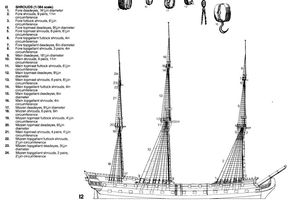
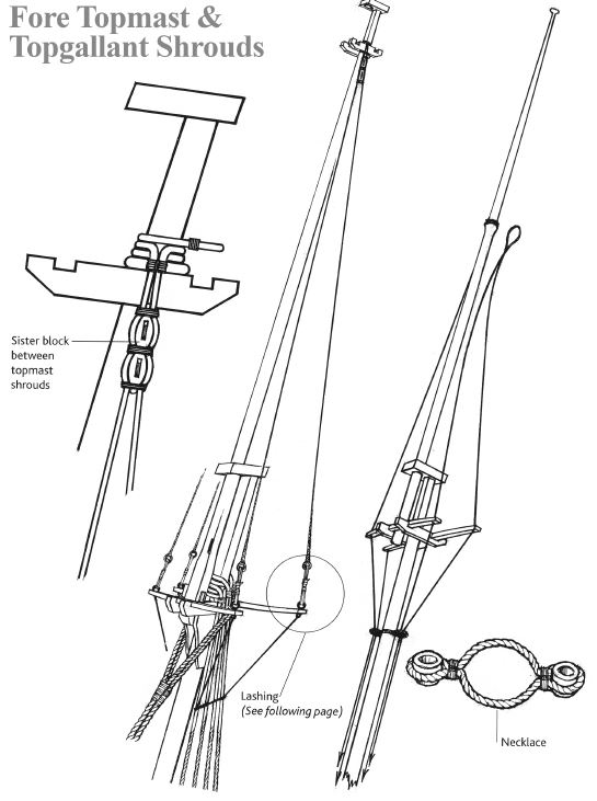
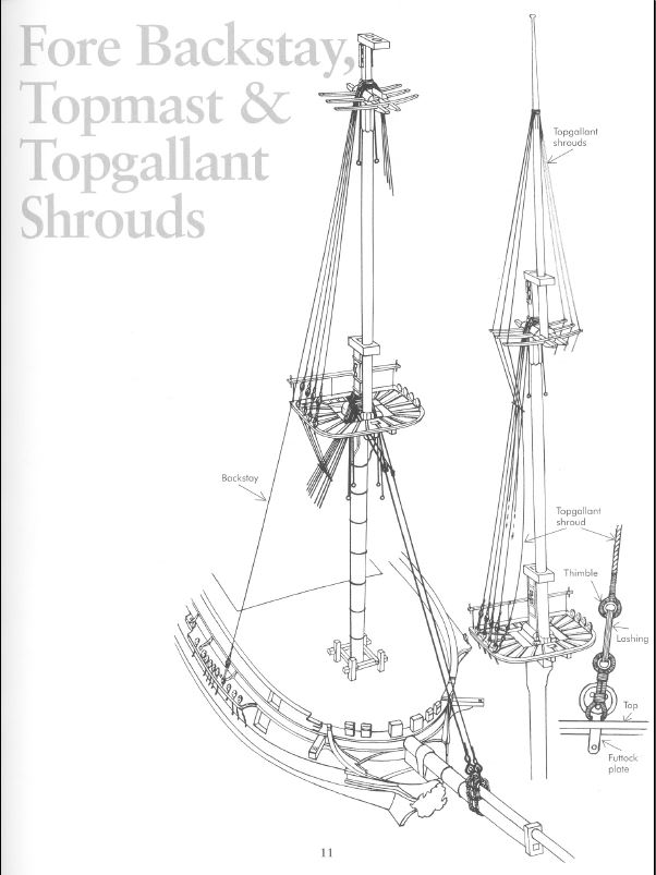
FYI - Anatomy of the 74 Gun Ship Bellona by Conway , page 96, plate 12, agrees with the rope sizes for the Victory.
See attached image
The only other reference I can find for the Topgallant Shroud connection to the mast is for American Schooners date early 1800's and they are similar to the Topmast Shrouds. There is a step in the diameter of the mast creating a shelf that acts as the stopper so they do not slide down.
I wonder if all ships with this rigging were similar?
-
-
-
-
AUG 20 2016
Sanded down a piece of eastern hemlock. It is thicker and wider than required.
Soaked it in alcohol for a minute.
Fit into place with some minor trim to the length and then clamped in place with elastic bands.
Letting it set now before I secure it and sand to fit. thickness and width.
This was harder than it seems as it took four attempts.
One broke.
One was trimmed too short.
One was clamped with real clamps and they damaged the surface.

-
19 AUG 2016
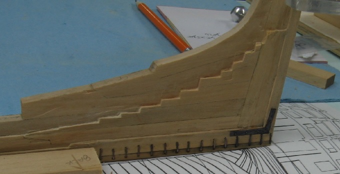
Completed the shaping of the stem assembly.
Chiselled in along the lower/middle/upper stem post to get the relief depth then sanded to shape.
Then did the same to the knee of the head and extension as it is narrower yet again.
Did a little damage on the edge of the filler pieces with the last step.
A little cleanup to be done on her... a few passes with finer grade paper and a tack cloth.
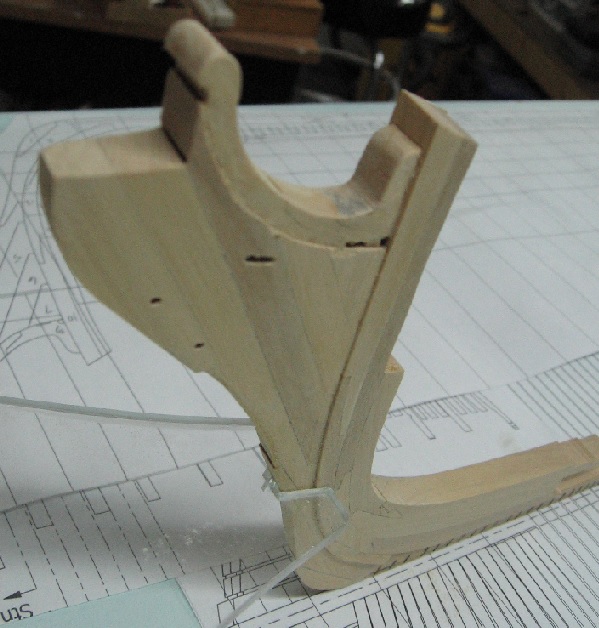
I have yet to add the cutwater strip to the stem assembly and the last pieces of the rising wood on top of the keel.
Then I will start building at the stern, adding the transom pieces.
-
-
Thank you jbshan for the idea.
As the stem assembly has yet to be sanded to thickness any edge bevelling would be lost.
I wonder if I can scrape something in after the re-shaping is complete? Will consider it when I get that part done.
Robin... It scares me too. Part of why I jumped into the deep end!


HMS Bellerophon 1786 by AON – scale 1:64 – 74-gun 3rd Rate Man of War - Arrogant-Class
in - Build logs for subjects built 1751 - 1800
Posted
Yes, I used LoS (Liver of sulphur) as before.
This time was better but third time will be the charm.