


AON
-
Posts
2,879 -
Joined
-
Last visited
Content Type
Profiles
Forums
Gallery
Events
Posts posted by AON
-
-
Okay....
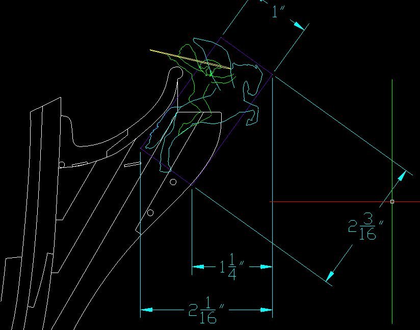
inserted the JPEG image of the actual NMM plan and traced it, then scaled it to fit my build scale.
Manipulated the figure head items.
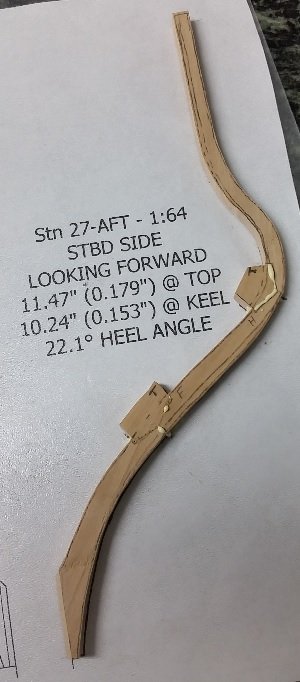
Here are the results.
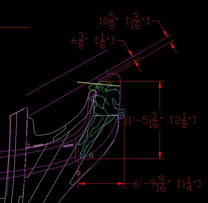
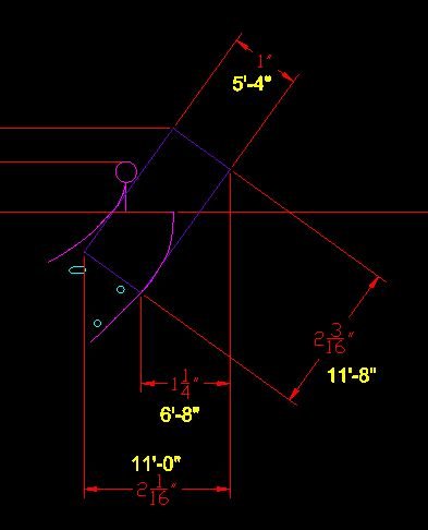
I added dual dimensions (both imperial feet-inches): actual ship size versus my model size.
The model size is quite small.
-
-
-
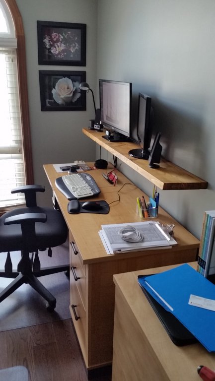
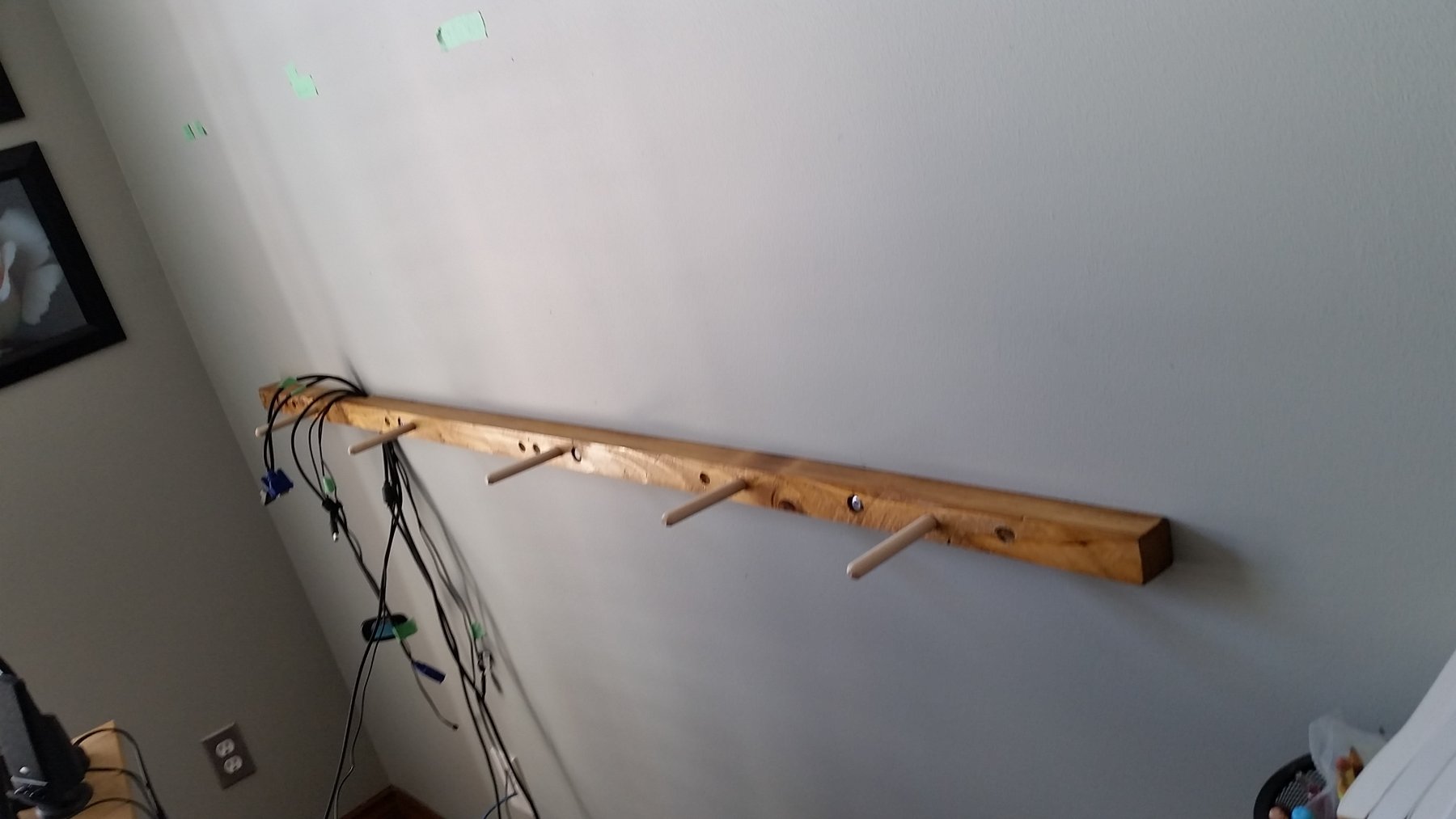
Mounted my floating shelf. Perfect height and matches the desk almost perfectly. The shelf is now out of the shipyard so I can get back to my frames tomorrow.

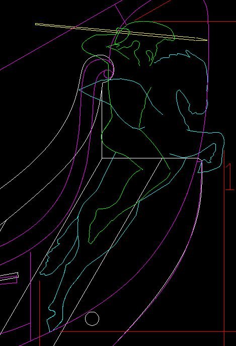
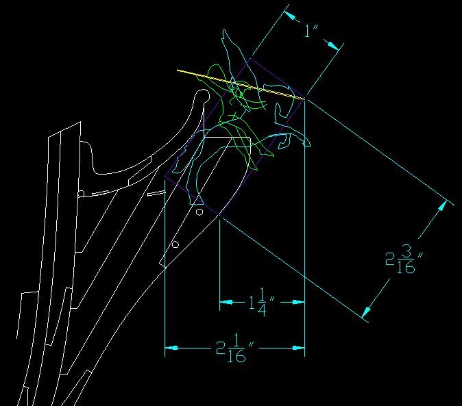
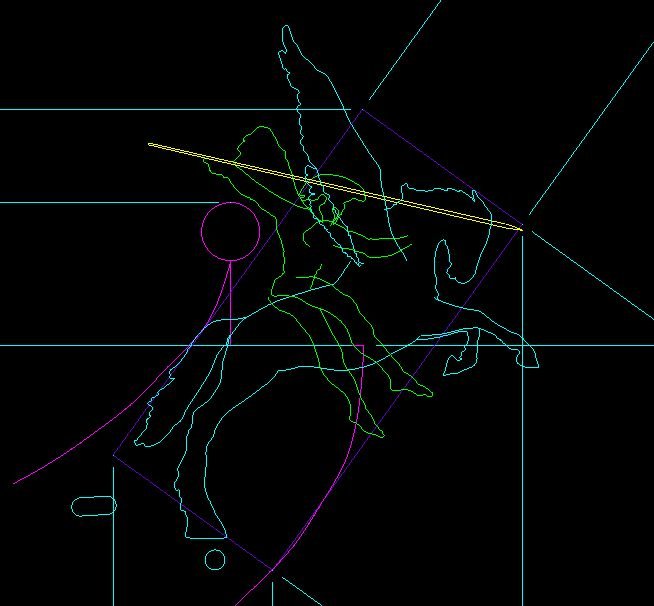
Completed my 13th version of my figurehead sketch. Pegasus is smaller and the body has been arched and rotated to pull the head closer to alignment inside the nose of the bobstay piece. I stole Druxey's hind leg (the sketch off his horse! I wouldn't want to be responsible for him being legless) and arm/spear arrangement. The wings are much smaller. Bellerophon is out of scale with Pegasus but he likely should be the predominate figure. The flying portion of the cloak (scarf) is gone but I feel a wrapped version will appear on the actual figure. I believe I will go with this for now.
My wife keeps asking me if I feel retired yet. I have no idea what that should feel like... I suppose that means I was ready.
- aviaamator, popash42, cog and 3 others
-
 6
6
-
-
Thank you Jason. Very kind words considering how little I think I've done to date.

I seem to be following the current and going in big circles.
I hope to break out of this pattern soon.
At this moment my floating shelf needs another coat of poly, my car cost me dearly (needed new rear brake pads and discs), and my latest plot of a figure head (version 11) is colourized and taped to the wall in front of me so I might ponder on it a bit.
-
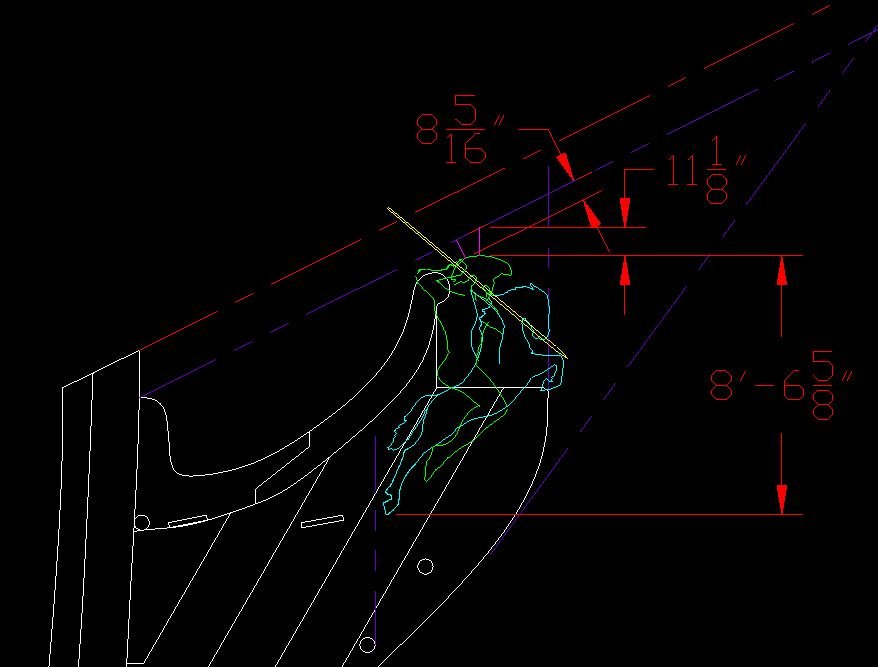
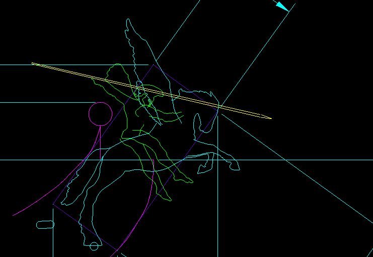
Tried to walk away but I just had to fold his legs back, shorten the wings more, shorten the pointy end of the spear, and clean up (simplify) the horses legs.
Now I need to let it rest a few days. Have been looking at numerous other figure heads and rigging and I was thinking along the lines of what you (Druxey) had sketched above.
Below is where I went. ... but I admit to liking your sketch a bit more. It fits better, better scale, alleviates concerns for clearance of rigging and bowsprit.
At this time sketches cost nothing but spark ideas and give me something to try to whittle (or carve or gouge). I think I have a far trip to develop a talent at this bit of wood magic before it can be considered I've gone to far down the road. I am sure the first 5 to 10 goes would not have a chance to get near my bow!
Thank you for having steered me.
I have to ask. How did you create such a nice looking sketch so damn fast?
(Talent?)
-
here it is with the bow sketch from my build template (I made the DXF and put it in my sketch).
-
Quite a bit has happened since my last post.
I am unofficially retired as of March 3rd (over a week ago). About 9 months earlier than planned but my employer made me an offer I couldn't refuse.
Still making frames. Reached over the model and snapped the top timber off one that was still attached. Remade it but none are attached as yet.
At the office I stood at my desk 90% of the time (one that adjusted) and now find my home desk computer screen height uncomfortable. So yesterday I made a floating shelf. It has been stained and needs a coat of Polyurethane before it gets mounted. This is taking up room in the shipyard (playroom) so, as I cannot work on the ship at the moment, I decided to work on sketches for my figurehead. I know I am getting way ahead of myself, but I also know this is going to take considerable amount of time, trial and error, to get right... so best start early.
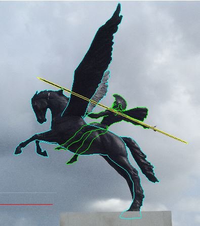
After searching the web I decided on an image I liked and might be able to manipulate.
I inserted the image into DraftSight (a free downloadable early version of AutoCAD) and traced the image.
I worked in layers, hence the three colours to differentiate the layers. I also used polylines and joined as many as possible.
I may have the back hoof too big.
I then inserted an image of my model's bow layout onto my sheet and traced it. I suppose I should have made a DXF of the drawing, copied and pasted it in.
DOH! I'll do that next time when I get a better sense of the figurehead.
I scaled the wings smaller as they are a bit large. Then I scaled Pegasus down leaving Bellerophon as is.
Then mirrored the whole thing so it was facing the same way as the bow and could be copied into my bow sketch.
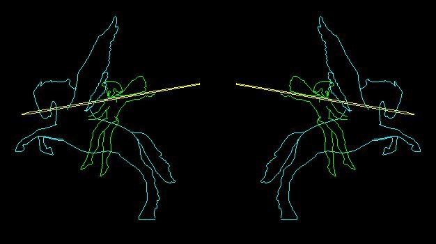
I inserted this into the bow sketch, scaled it up to suit, rotated and took it in for a bit... let it soak in my brain.
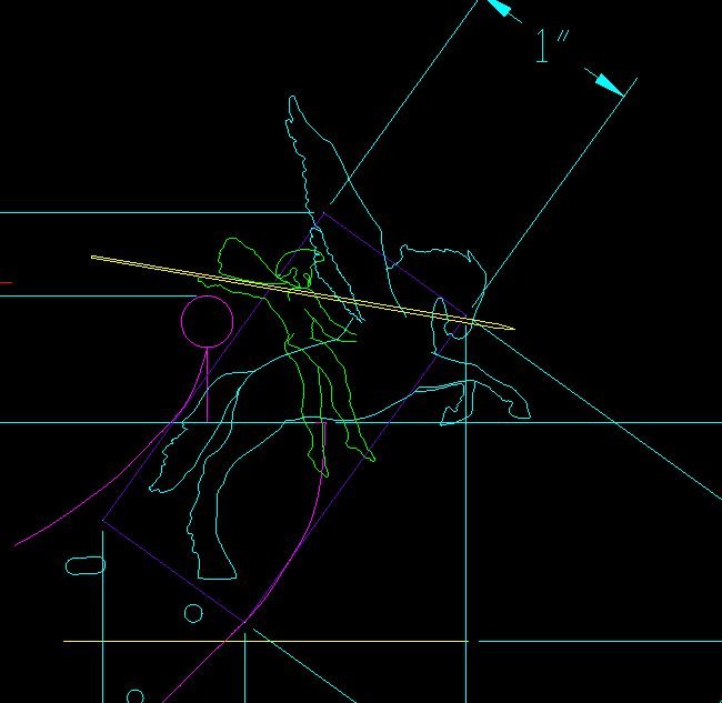
Next I rotated Bellerophon, leaning him forward.
Rotated his right arm and both legs.
and finally shortened the spear.
I think she is getting there. The spear isn't quite right. Might need to fold the legs back at the knees.
I'll let this percolate a bit and come back to it later.
But you can get a sense of where I am going.
A special thank you to RMC for sending me some measurements off his Vanguard model and the optional 2nd Bellerophon figure head he had in his kit.
I've asked for a couple more measurements to help refine my sketch area.
Now I think I'll work on the 1:48 scale template drawings Gary requested a while ago (but I suggested he wait until I retired as I'd have more time then).
Then I have a shelf to put up, frames to make and install, take my car in for her regular maintenance....
-
Been there twice Tom.
In 2007 lost my job in a place I had given 29 1/2 years. There was a lot of talent let go in three waves. I was lucky to quickly find another job but then came the crash of 2008.
I told myself business is business and they are in it to make money not keep me employed. Loyalty is a one way street.
You have to keep trying, as miserable and cheated as you feel right now, it will get better. It wasn't you, and although this feels like a tidal wave this is just a ripple.
Take care and climb back on the saddle.
-
-
Spent about 90 minutes visiting (at his invitation) one of our local model club members. He understands this is my first ever scratch build ship and we both understand I know next to nothing. As my wife said to me as I went out the door: I am so blessed to live so close to such a skilled model maker. There are few real gentlemen and just plain thoughtful and sharing people in this world.
Came home and tore everything off the port side to match the starboard side to allow me to follow his suggestions. I must admit it didn't hurt to remove them this time. I believe I have become immune to the pain.
He recommended I consider making and spot gluing all the frames in place so I might remove them later. They need to be marked (I'll do this at the heel) with their station numbers. As a group are installed I should sand them to shape while I can still easily reach inside. Once all are installed I can apply a batten at the proper distances above the gun decks and lightly mark off the gunport top/bottom openings in one step, marking an X on each frame to indicate what to cut out.
Then I should remove the frames and cut out each gunport individually. The loose pieces above need to be lightly marked with station numbers on the same face as the lower portion, and indicate which end is the top (an arrow pointing upwards) so they get reinstalled properly. Then (finally) reinstall them permanently.He also spent time demonstrated to me how make clean shallow cuts for the cills (sills) with a chisel, and described how he would make cills to match and fit, which was almost identical to what I had done (making the cills, not the cut outs).
So I am back to making the same frames, over, again. I admit, that part just plain pisses me off.
It will be worth it in the end. It will be worth it in the end. It will be worth it in the end.
I purposely haven't mentioned the gentleman's name as he doesn't share his knowledge or personal time for any acknowledgement. He does it because it is his choice, because he can, and it seemed to him I might be heading down a road filled with aggravation. Since he had been there many years ago, he might save me from some of it if I wasn't too thick headed to listen. (Okay, I added the thick headed part because I know me).Once again, thank you.
I hope to return the favour by sharing with some unfortunate modeller down the road... after I am blessed with some skill to share.
-
Made (remade?) my frame: starboard 27 aft. set it aside to dry and cure.
Worked on the port side gunport; filed the opening and installed the cills (sills).
I will prepare the new frame tomorrow (shape the chocks, sand to thickness, install the bolts) for installation, and I'll cut out the upper port side gunport.
-
-
-
Good morning Jaager.
I have looked and see square and parallelogram shapes. I believe the square is simplifying the ports. I believe you are correct.
I could not understand how a parallelogram shaped port could swing open without binding.
Then I found the answer.
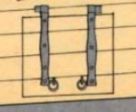
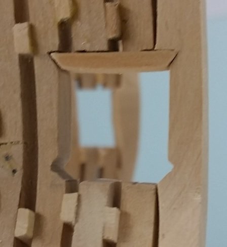
In The 74 Gun Ship, Volume 2, page 35 fig. 125 I found the following figure.
At the same time moments ago I received a private e-mail from Druxey explaining exactly the same thing!
The hinges are square to the vertical sides, not parallel to the skewed top. You can see in the image that the left hinge is higher above the top to the cover than the right hinge.
I've looked and cannot seem to see how I might salvage my first ever gunport. If I cannot, I will be tearing out four frames on the starboard side. Having done it before (tearing frames out), I cannot say it is getting easier.
-
Good evening Jaager
My aft gun ports are higher aft but the opening is square. The draught I am looking at is a 2D image of a 3D object. I read it to be a standard square opening with simple square port covers. I have not seen one in real life so this is what I understood the frame draught to be showing me.
Alan
-
Druxey
I understood your Sunday post clearly and planned to follow it (which was my original plan) once these four are done.
Are you suggesting that I should remove the installed frames that are chocked and glued, disassembling them, clean them, cut the ports, and then reassemble them?
This seems riskier than cutting one more upper gunport.
Looking forward to discussing this in person!
Alan
-
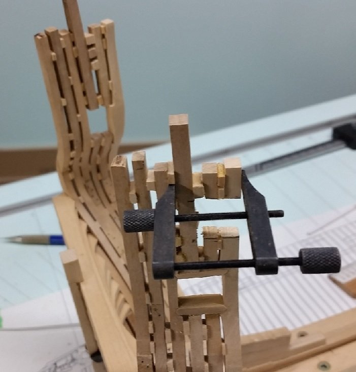
Well, it happened.
I made my lower cill (sill) and installed both upper and lower permanently.
Let the glue dry and set.
Shaped the next set of frames in readiness as they reach into the upper gunport opening (similarly to the lower opening) so when installed they will add support.
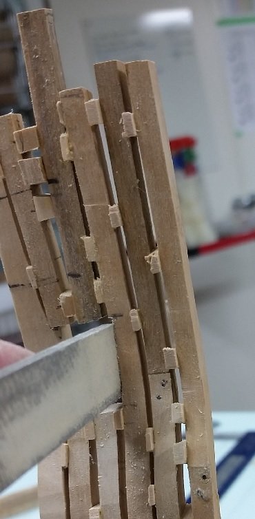
Then I carefully, very light strokes, sawed the frames for the upper gunport.
Cut through the first timber with out incident... the toptimbers snapped off with the next cut.
So, they are glued on and need to set before I attempt anything more.
I was going to take it to our club meeting tomorrow but I feel it is too delicate... particularly with the ice and more snow on it's way tomorrow.
Regardless, I am looking forward to the rope walk demo.
I will take it to the next meeting at Lee Valley Tools in Niagara Falls next month.
-
Mark and Gary,
Thank you for the suggestions. I understand both... your explanations were very clear.
I find sanding on a stationary grit platform works well until the pieces get so small I start sanding my finger tips!
So I tried putting the tiny piece on the stationary grit and used a sanding board above.
Normally the small piece stays stationary if the bottom paper's grit is large enough to hold it and the sanding board above does all the work.
Some times the small piece rolls. That is when it gets frustrating. This happens with my tiny chocks that fit between frames as some are very thin.
I've thought of trying double sided tape.
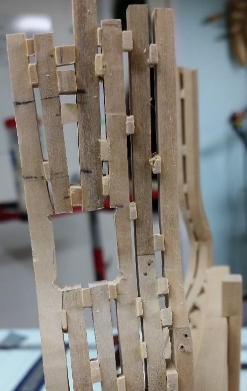
As soon as I started cutting out the gunport with one end open I started to worry about the top half breaking away.
My original idea was to assembly with a roughed in opening and then sand to a scribed line.
At least this way the gunport would be closed on four sides and better supported/stiffened.
I listened to people in our club that had some experience as I have none.
(Of course this was the day David Antscherl couldn't make the meeting)
It must have worked well for them, but leaves me worried every time I draw on the saw.
I had to go very very lightly.
I am committed with this method on this set and the one above but will revert to my original method on the next set to see if it is any better.
I really want to install the gunports as the timbers go up.
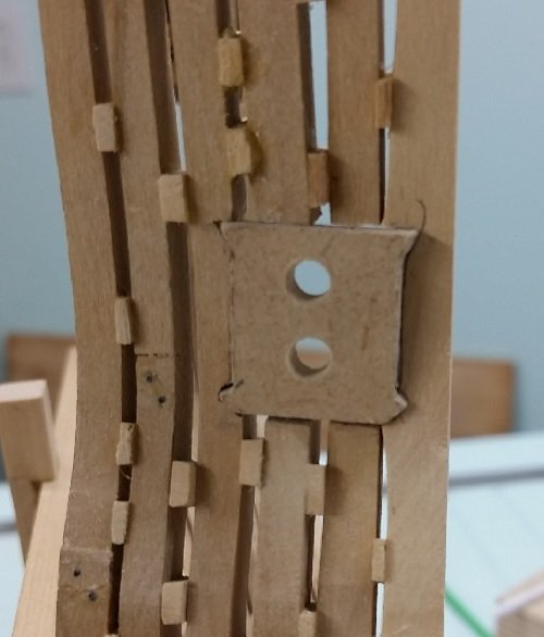
I will try the card stock method to get a better fit on the cill.
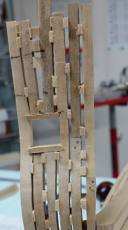
On another note. The photo shows every deformity.
Looking at it in real life is a whole other story. That last upper cill looks pretty darned good and I might keep it.
I'll work on the lower cill and see if I feel the same way by the weekend.
-
Good morning Carl.
I only use the template to check layout and check the gunport opening.
The cill is beveled slightly and checked for fit, sharpened a bit and checked again, and repeated.
Once it is close I mark off the length and start the bevel process on the other end, keeping the length a wee bit proud (too long).
When that seems correct then I shorten the length sanding at an angle and checking the fit very often.
Once I have that then I sand the thickness.
This last one was exactly 6" thick... I almost went too far.
-
-
-
It was a very busy weekend and I didn't get to put in the time on the ship I had thought I might.
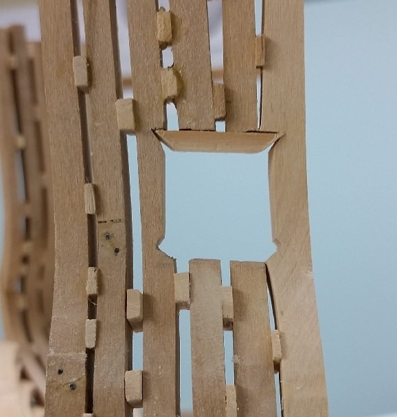
After transferring/marking the four corners I filed and sanded one gunport. Double checked it with my gauge which nearly slides in. I fear if I work at it much more it might be too large.
I then worked at a trial for the gunport upper cill using a piece of scrap hemlock. The height thickness is 6" (0.094" or 2.4 mm). I cut the length a bit longer and then placed in on a strip of rough sand paper to hold it in place while I sanded it from above using a sanding stick, checking the thickness with my caliper as I went along. I wasn't worried about it being exact thickness, having it a wee bit thicker is better than too thin.
I bevelled one end and it seemed to fit well but it could not be inserted because the piece was still too long. I transferred/marked off the length and then sanded it down while bevelling. I kept trying the fit until I had the length correct... but you can see the bevel is all wrong.
I need to work at this to get a better fitting cill. Once I figure this out I have the joy of the lower cill. I will not shaped the port gunport until I get this one figured out.


HMS Bellerophon 1786 by AON – scale 1:64 – 74-gun 3rd Rate Man of War - Arrogant-Class
in - Build logs for subjects built 1751 - 1800
Posted
David, I will always be interested in any and all comments, suggestions and help. As you know I might circle around a bit before I agree or follow what was actually the best advice. I call this my learning curve. It is steep and mostly my own doing.
I have about 20 different images of Bellerophon and Pegasus together and about 17 of Pegasus alone. One has Bellerophon and a wingless Pegasus which in my mind is more believable as the wings represent speed and so do not have to be factual... but then there is the beast to contend with.
Of all of these images I've collected only one has the wings behind Bellerophon's legs and I am not a fan of how it looks but I imagine it may have kept his legs from getting beaten and chafed.
Here it is...
If you have a different one please send it over!