alross2 Posted April 5, 2021 #1 Posted April 5, 2021 The photoetch for OREGON arrived Thursday and I checked it out today, so Tuesday I'll be back on OREGON. The development log (DLOG) for WYOMING will go into hiatus for a bit. The development of the OREGON kit was fairly well along before I decided to create these logs, so I'll be including some prior work just to give you an idea of what transpired before. The photoetched brass comprises three sheets: .005", .010", & .020". Here are partial scans of each sheet (reduced): .005" - turret rings, 6 pdr shields and shoulder rests torpedo tube covers, deck plates for various fittings, crane parts, coal scuttles. .010" - inclined ladders, gunner's grates, jacobs ladders, bow shield, 6" casemate covers, hatch covers. .020" - awning stanchions, main deck stanchions, railings, searchlight platforms, binnacle tower. coxswain, ccoyle, GuntherMT and 7 others 10
alross2 Posted April 5, 2021 Author #2 Posted April 5, 2021 (edited) One of the initial challenges I came across in the early stages was the prominent anchor bills. They are angular and have some difficult angles where the wedge shape meets the vertical walls. I tried carving them into the hull, but wasn't satisfied with the outcome, as they weren't exactly the same. So, I decided to cut a channel across the hull and laser-cut inserts that ensure consistency - worked much better. There are two pairs of lifts that allow the builder some adjustment capability incase he/she didn't shape the hull quite to specs...🙄 The inserts are separate, as well, so the angle can be shaped before they are inserted. Once the basic assembly is complete, the hull is filled and finish-sanded to shape. A laser-cut deck of glued-up decking will be fitted, so the lamination does not affect the appearance. These are the inserts, before (left) and after (right) shaping. Lasered lifts for the anchor bills. This is what it looks like much later in the process. Edited April 5, 2021 by alross2 coxswain, thibaultron, Canute and 7 others 10
ccoyle Posted April 5, 2021 #3 Posted April 5, 2021 Hey, Al. I'm very fond of pre-Dreadnoughts, so I will watch this with interest. I added a little substance to your title so that folks won't be confuzzled about what a "dlog" is. Cheers! alross2, mtaylor, Canute and 3 others 5 1 Chris Coyle Greer, South Carolina When you have to shoot, shoot. Don't talk. - Tuco Current builds: Brigantine Phoenix, Mitsubishi A6M5a,
alross2 Posted April 5, 2021 Author #4 Posted April 5, 2021 (edited) There are a lot of airports in the hull and little looks worse than a wavy line of them. The kit includes laser-cut templates that are taped to the hull at the deck level with drilling dots that are inline and at the correct depth below the main deck. Once taped in place, an awl is used to mark the centerlines. The holes are drilled out with a 5/32" drill bit, lengths of aluminum tube are inserted into the holes and glued. When the hull is finished sanded, the tube will be flush with hull sides. Edited April 5, 2021 by alross2 GrandpaPhil, Ryland Craze, GuntherMT and 6 others 9
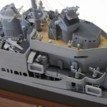
alross2 Posted April 6, 2021 Author #5 Posted April 6, 2021 Playing with the photoetch. This is the platform for the aft binnacle on the hurricane deck. There are five pieces and the x bars are recessed. When complete, there will be a cast binnacle and PE rails & vertical ladder. gieb8688, mtaylor, thibaultron and 5 others 8
alross2 Posted April 6, 2021 Author #6 Posted April 6, 2021 Spent an hour or so this morning masking off the deck surfaces in preparation for painting. It's tedious, but makes painting a whole lot easier, especially if you airbrush. GuntherMT, gieb8688, thibaultron and 6 others 9
Dr PR Posted April 7, 2021 #7 Posted April 7, 2021 I recall seeing a very nice large scale (1:96 or 1:48?) model of the USS Oregon in the maritime museum in Astoria, Oregon, about 45 years ago. I visited again a few years ago and the model wasn't there any more. I have no idea what happened to it. Canute, thibaultron, lmagna and 1 other 1 3 Phil Current build: Vanguard Models 18 foot cutter Current build: USS Cape MSI-2 Current build: Albatros topsail schooner Previous build: USS Oklahoma City CLG-5 CAD model
Kevin Posted April 7, 2021 #8 Posted April 7, 2021 that looks fantastic thibaultron, mtaylor, lmagna and 1 other 4 Its all part of Kev's journey, bit like going to the dark side, but with the lights on All the best Kevin SAY NO TO PIRACY. SUPPORT ORIGINAL IDEAS AND MANUFACTURERS. KEEP IT REAL! ------------------------------------------------------------------------------------------ On the build table Oseberg' Viking Ship (v3) by Kevin - Pavel Nikitin - 1/25 - started June 2025 On hold Santisima Trinidad – 1/84 - Artesanía Latina - by Kevin - started June 2025 - MHS Britannic by Kevin Bluebell - Flower Class - Revel - 1/72 U552 German U Boat Trumpeter 1/48 Amerigo Vespucci - 1/84 - Panart- HMS Enterprise -CAF - 1/48 Finished HMS Indefatigable 1794 - Vanguard Models - 1:64 Belle Poule 1834 - OcCre - 1/90 - French frigate Hercules - OcCre - 1/50 - Tugboat ST Nectan-Mountfleet-models-steam-trawler-1/32 HMS Victory - Caldercraft/Jotika - 1/72 Dorade A renamed Dora - Amati - 1/20 Stage Coach 1848 - Artesania Latina - 1/10 Lady Eleanor - Vanguard Models - 1/64 - Fifie fishing boat
alross2 Posted April 7, 2021 Author #9 Posted April 7, 2021 Grates dry-fitted to a couple of the cast resin superstructure deck houses. The houses will be painted buff and the area under the grates black. I may leave the grates in their natural brass for eye-interest. nehemiah, ccoyle, gieb8688 and 8 others 11
alross2 Posted April 7, 2021 Author #10 Posted April 7, 2021 A test assembly of one of the exposed 6 pdr guns, less shield. It's a bit rough, but I was fiddling around with the pieces trying to figure out the best assembly sequence. It came down to lightly gluing the base and pedestal to a piece of masking tape around a stick, inserting the gun peg though the hole on the legs, gluing that assembly to the pedestal, cutting away the arcs holding the ends of the legs, bending down the legs with a hobby knife, gluing them to the base, and trimming them with the hobby knife. The tape is removed from the wood and trimmed away from the gun. It's a bit of a fiddly process, but comes out fine if you take your time. GuntherMT, coxswain, mtaylor and 7 others 10
Roger Pellett Posted April 7, 2021 #11 Posted April 7, 2021 Al, What is the scale of this model? lmagna, thibaultron, Canute and 1 other 4
thibaultron Posted April 7, 2021 #12 Posted April 7, 2021 Might I suggest some little laser cut ribs, to go inside the gun base, so you can bend the brass stock curves, smoothly? They could then be removed after the base is completed. Perhaps one set could be reused for the other bases. mtaylor, Canute and lmagna 3 Ron Thibault
alross2 Posted April 9, 2021 Author #13 Posted April 9, 2021 On 4/7/2021 at 1:05 PM, Roger Pellett said: Al, What is the scale of this model? 1/128 (3/32" = 1') Same scale as the MAINE and OLYMPIA kits from 2005, 2006. On 4/7/2021 at 1:57 PM, thibaultron said: Might I suggest some little laser cut ribs, to go inside the gun base, so you can bend the brass stock curves, smoothly? They could then be removed after the base is completed. Perhaps one set could be reused for the other bases. I may make a resin plug as a bending jig. If that works, I'll include it in the kit. thibaultron, Canute, mtaylor and 1 other 4
alross2 Posted April 9, 2021 Author #14 Posted April 9, 2021 (edited) Yesterday I made a jig for bending the legs on the 6 pdr mounts and will be including a resin cast version in the kits. It works well and the finished product is much better than the initial attempts. Edited April 9, 2021 by alross2 lmagna, mtaylor, Ryland Craze and 6 others 9
alross2 Posted April 13, 2021 Author #15 Posted April 13, 2021 (edited) Starting to attach the brass to the hull. Aft 6pdr casemate. The hinges are separate. The various deck hatches and the winch house prior to priming. Torpedo tube covers. There are two on each side. Edited April 13, 2021 by alross2 Canute, GrandpaPhil, GuntherMT and 5 others 8
alross2 Posted April 14, 2021 Author #16 Posted April 14, 2021 Today is going over the drawings day, checking out what's already done and what further ones are needed. Because this is a solid hull, I'm including hull templates that are laser-cut from poster board. It'll save the modeler a bit of time and expense. In addition to the hull sections, there are templates for drilling the air ports, the stanchions, and a few others. There are two more sheets besides this one, those being the plan and profile with stations. GuntherMT, GrandpaPhil, coxswain and 5 others 8
alross2 Posted April 14, 2021 Author #17 Posted April 14, 2021 (edited) One or two of the plans will be the normal large sheet (the general arrangement plan is 28" x 40"), but most will be in a spiral-bound booklet of 11" x 17" pages. The drawings on the smaller sheets will be full size, so measurements can be taken directly from them. The smaller size is just handier to use and doesn't take up a lot of workbench space. It also isolates each component, making it less confusing than an overall drawing. The large sheet (not quite complete) showing the overall model. I still have to add rigging and a few other details. A few of the 11" x 17" sheets will have a couple drawings due to the small size of the item being assembled/built. Most of the 11" x 17" sheets will have a single topic to be addressed. Both the main and superstructure decks have the positions of the various components laser-etched on them, making placement a bit easier than trying to measure everything. Edited April 14, 2021 by alross2 ccoyle, gieb8688, thibaultron and 6 others 9
alross2 Posted April 15, 2021 Author #18 Posted April 15, 2021 (edited) A couple more drawings today. These are for the 6 pdr guns, of which there are 18. This is in progress and will eventually show the construction details, most likely in a larger scale as no measurements are needed. For the superdetailers, I've done these in 1/32 scale, along with an actual size drawing. Edited April 15, 2021 by alross2 thibaultron, GrandpaPhil, coxswain and 6 others 9
alross2 Posted April 16, 2021 Author #19 Posted April 16, 2021 (edited) Another drawing day, mostly cleaning up earlier ones. Here's one. And the finished version of one from yesterday. Edited April 16, 2021 by alross2 GuntherMT, mtaylor, thibaultron and 5 others 8
alross2 Posted April 20, 2021 Author #20 Posted April 20, 2021 I do like jigs. This is a simple one I created this morning, but it will be a time saver. It is for locating the bilge keels on the hull. When viewed from below, bilge keels run parallel to the keel. Because of the shape of the hull, when viewed from the side, they usually form an arc and this is sometimes difficult to achieve correctly. To use this jig, you place the line on its center on the centerline of the hull, drop a pencil through the holes and mark the position of the bilge keels along the hull at each end and the center of the bilge keel location. You then use a batten and pencil to connect the dots and it will give you a fair curve. Roger Pellett, gieb8688, hollowneck and 6 others 9
alross2 Posted April 20, 2021 Author #21 Posted April 20, 2021 Another of today's creations. This shows the jig used for aligning the prop shafts and the prop strut arrangement. Keep in mind that there will be associated text in the manual. 3Will Day and 2 others Seen by 9 lmagna, thibaultron, Ryland Craze and 7 others 10
Kevin Posted April 20, 2021 #22 Posted April 20, 2021 those jigs will save someone so much time Canute, lmagna, thibaultron and 1 other 4 Its all part of Kev's journey, bit like going to the dark side, but with the lights on All the best Kevin SAY NO TO PIRACY. SUPPORT ORIGINAL IDEAS AND MANUFACTURERS. KEEP IT REAL! ------------------------------------------------------------------------------------------ On the build table Oseberg' Viking Ship (v3) by Kevin - Pavel Nikitin - 1/25 - started June 2025 On hold Santisima Trinidad – 1/84 - Artesanía Latina - by Kevin - started June 2025 - MHS Britannic by Kevin Bluebell - Flower Class - Revel - 1/72 U552 German U Boat Trumpeter 1/48 Amerigo Vespucci - 1/84 - Panart- HMS Enterprise -CAF - 1/48 Finished HMS Indefatigable 1794 - Vanguard Models - 1:64 Belle Poule 1834 - OcCre - 1/90 - French frigate Hercules - OcCre - 1/50 - Tugboat ST Nectan-Mountfleet-models-steam-trawler-1/32 HMS Victory - Caldercraft/Jotika - 1/72 Dorade A renamed Dora - Amati - 1/20 Stage Coach 1848 - Artesania Latina - 1/10 Lady Eleanor - Vanguard Models - 1/64 - Fifie fishing boat
alross2 Posted April 21, 2021 Author #23 Posted April 21, 2021 The pilot house itself is not a complex assembly and is built upside down over a form. The angled cuts at the back of the form are to prevent the sides from sticking to it when they are glued together. The sides are .015" laser board, which bends well. The bluish green items are clear styrene strips which will be inserted after the pilot house is assembled and painted. GrandpaPhil, mtaylor, Canute and 5 others 8
alross2 Posted April 22, 2021 Author #24 Posted April 22, 2021 (edited) I always cut a slot for the bilge keels as it is sturdier than just gluing them to the surface of the hull. After using the marking jig and using the batten to form a fair curve, I cut along the curve at about a 45 degree angle with a hobby knife, then use a slot head screwdriver to widen and deepen the knife cut to 1/16" or so. If you take you take your time and don't force it, the screwdriver works well. Once the slot is incised, you can dry fit the bilge keel in place to ensure fairness, adjust the slot if necessary, then glue the bilge keel in place. A bit of filler will take care of any resultant gaps. Edited April 22, 2021 by alross2 hollowneck, coxswain, thibaultron and 5 others 8
alross2 Posted April 22, 2021 Author #25 Posted April 22, 2021 (edited) Here's the prop shaft and strut alignment jig in use. The assembled jig Aligning the prop shaft boss. Slot cut for the strut. Strut in place. Strut and boss aligned. Edited April 22, 2021 by alross2 Ron Burns, ccoyle, mtaylor and 6 others 9
alross2 Posted April 23, 2021 Author #26 Posted April 23, 2021 This one required some rework, but should be OK now. It shows the layout of the hammock storage structure. The gunner's grates are only 3/8" x 1/2", but are photo-etched and have the holes completely through. When not in use, they folded down. The pale yellow on the lower section represents silkspan which is used to simulate the canvas curtain over the hammock storage. lmagna, mtaylor, thibaultron and 6 others 9
alross2 Posted April 27, 2021 Author #27 Posted April 27, 2021 Not many more drawings to do for OREGON. Finished this one today. ccoyle, lmagna, GrandpaPhil and 7 others 10
alross2 Posted April 30, 2021 Author #28 Posted April 30, 2021 This morning's activity. I had to reduce it to fit the 11 x 17 format, thus the dimensions. Canute, GuntherMT, hollowneck and 5 others 8
thibaultron Posted April 30, 2021 #29 Posted April 30, 2021 You might want to add an additional dimension, to one end of the belt, from the CL. mtaylor, Canute, lmagna and 1 other 4 Ron Thibault
alross2 Posted April 30, 2021 Author #30 Posted April 30, 2021 13 minutes ago, thibaultron said: You might want to add an additional dimension, to one end of the belt, from the CL. Thanks, Ron. The centerline for the 6 pdr casemate is also that for the armor belt and that will be stated in the instructions. thibaultron, hollowneck, lmagna and 2 others 5

Recommended Posts