Search the Community
Showing results for tags 'nrg'.
-
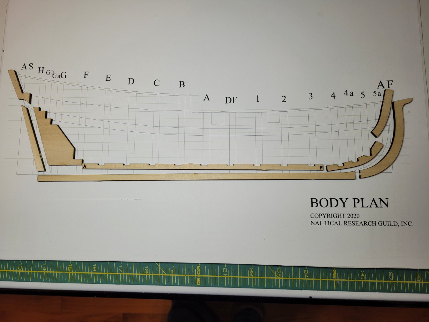
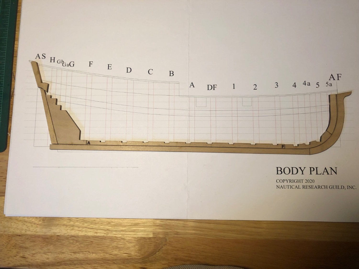
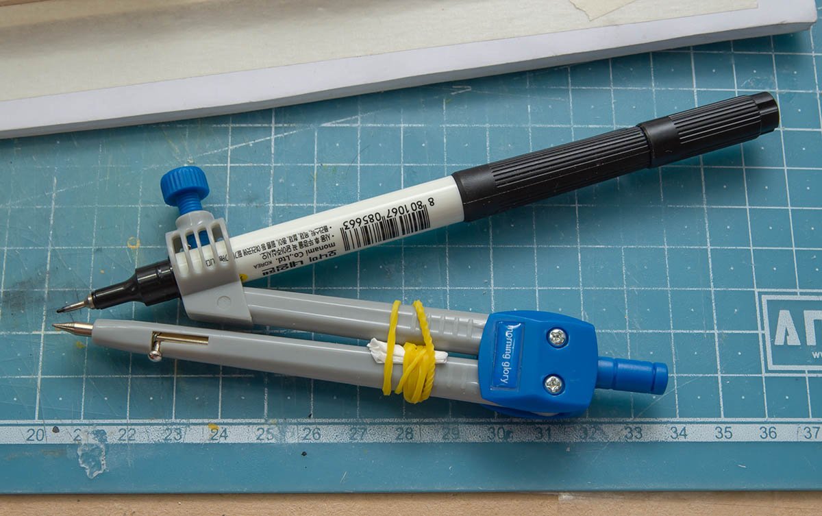
 While working on my latest model, HM Cutter Trial from Vanguard Models, I realised that it would be a good idea to have some further practice in hull preparation and planking before embarking on another full ship project. I’m hoping that this project will teach me some new techniques and help me make a better job of planking than I have previously. I am using the suggested ¼” foam-board as a base on which to build and used spraymount to glue the body plan to it. Laying out the keel, keelson stem and stern, it is clear that some trimming and fitting of the bow keelson is needed The whole kit is made in basswood making it pretty easy to cut and sand. The risk is taking off too much so slow and easy is the rule. Once the stemson is cut to length and sanded to fit the keelson lines up pretty well with the drawing. I didn’t need to fettle any of the slots for the bulkhead on the main keelson but the bow keelson required a bit of a tickle with a sanding stick. The rabbet is marked up with a pair of compasses. I measured the thickness of the sheets provided for planking which varied between 0.85 and 0.99mm. I took 0.9 as a rough mean and marked the rabbet. I used a chisel to remove the rough, then a file and finally scraped it clean with a razor blade. The keel and keelson were straightforward as a simplified 45º angle was used for the whole length. The stem is a little more difficult to do with a changing angle as the rabbet rises up the the stem pieces. However the manual provided and Toni’s log Half Hull Planking Project - Planking Downloads and Tutorials and Videos - Model Ship World™ provide plenty of useful detail and photos to help work it out Once the rabbet is cut, the keel and stem pieces can be glued up. I have used minimal glue to fix the pieces to the board to make it easier to remove the model when completed. At this stage the deadwood and stern pieces are not glued . David
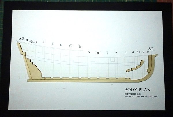
- 15 replies
-
- 7
-

-
- half hull
- Half Hull Planking Project
- (and 2 more)
-
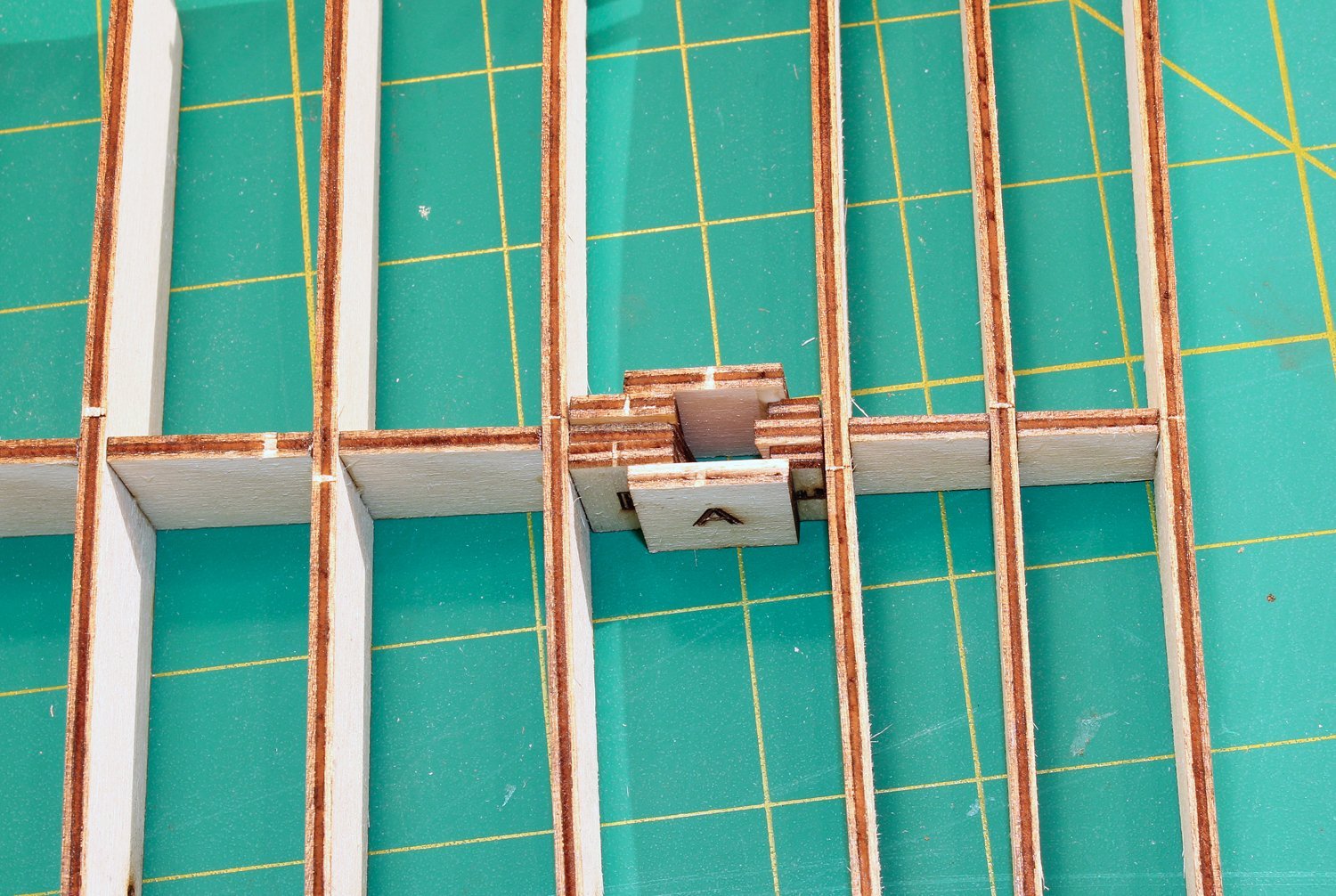
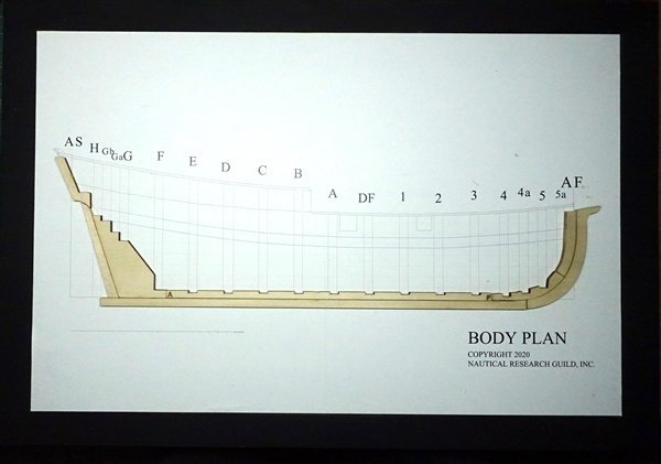
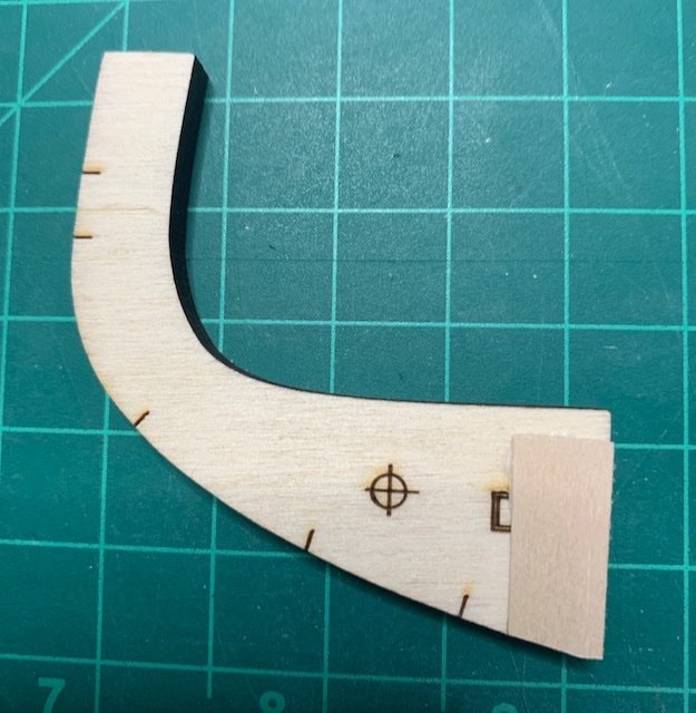
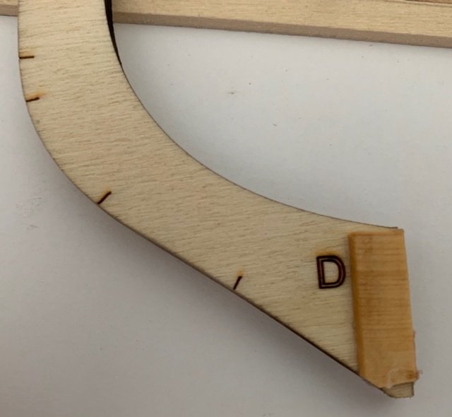
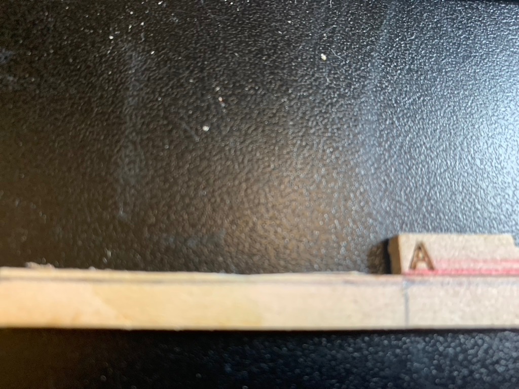
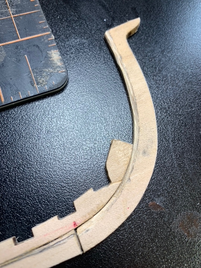
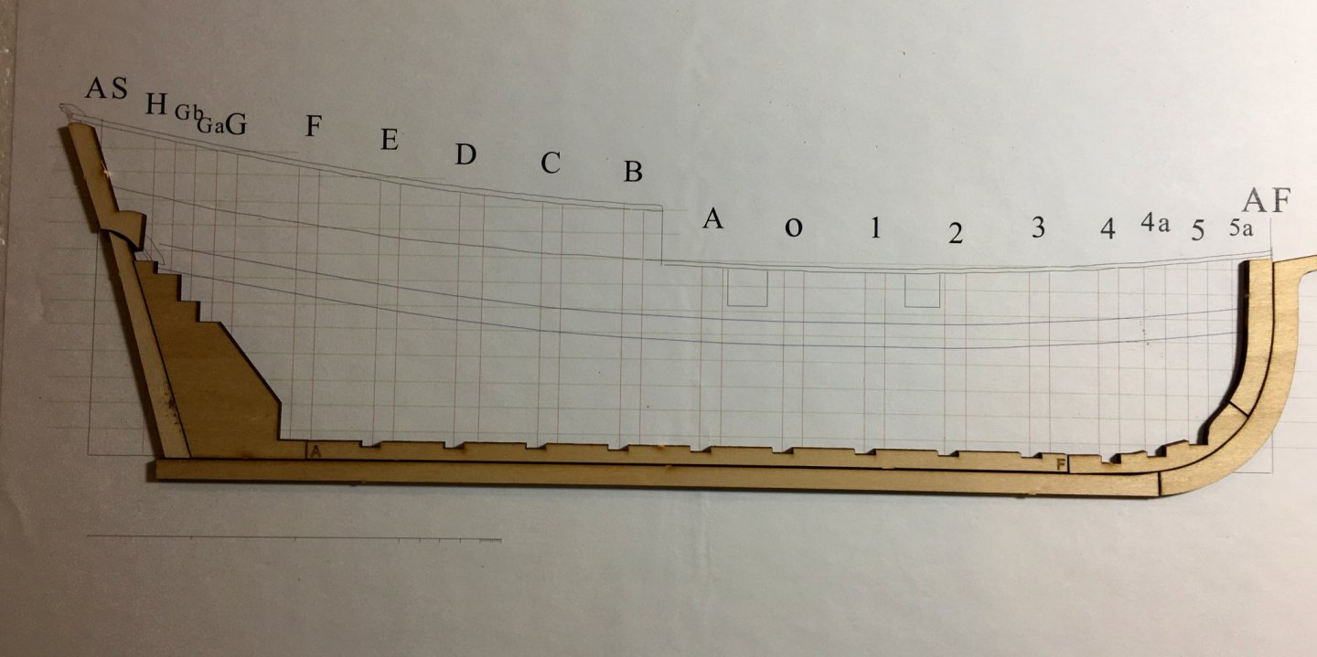
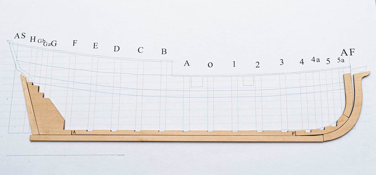
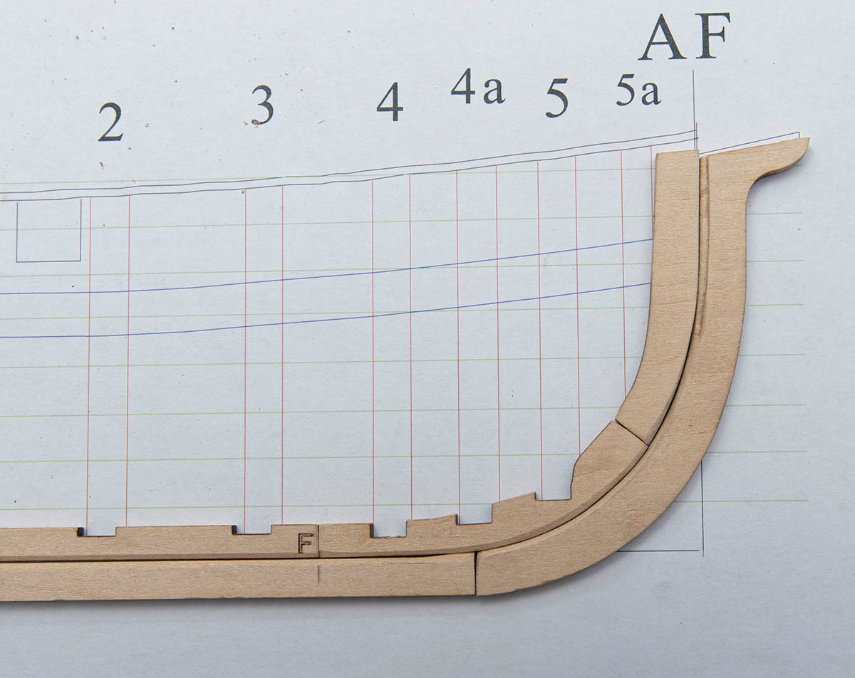
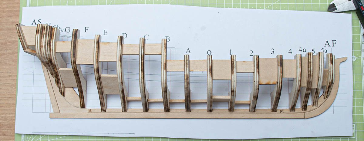
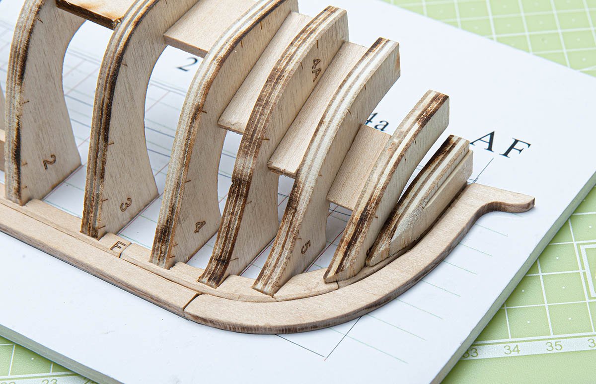
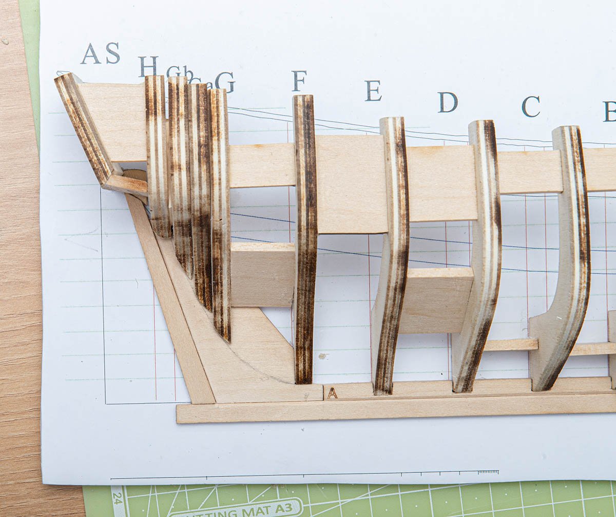
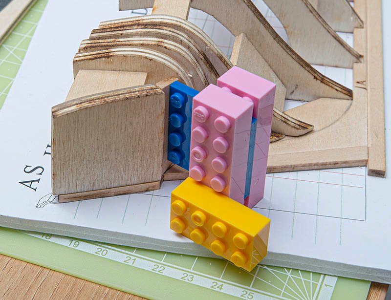
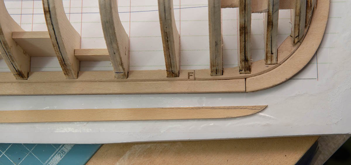
 Although I'm still working on my scratch-builds, I got started on this recently. I received the NRG Half-Hull Planking Kit as a Christmas gift. I'm looking forward to building it and learning a lot about planking a curved hull in the process. I'm also glad that the result should be relatively easy to store, display, and transport, as I don't have a ton of room. Given work, I will probably be building this pretty slowly. As can be seen, the kit is pretty straightforward in terms of components. Overall it looks like a nice kit, and the instructions are quite thorough, which I appreciate. I'm still waiting on getting a foam building board, so nothing is glued yet, but I've sanded off the laser char and removed the basswood parts of the model's backbone (keel, stem, etc). In general, the parts fit together well with minimal sanding, although I'll have to do a little more shaping where the keel rises slightly near the stem. The keelson slots fit the frames well. However, there is a slight issue with the fore keelson, and I thought I'd ask for advice before proceeding. The slots in the fore keelson don't line up with the markings for the frames on the plans. I see two main ways I could deal with this. One would be to trim the end of the fore keelson so it aligns better with the frame markings--more or less like below, although there the fore keelson is propped up above the other parts. That said, if I do this I'll be throwing off the fit of the stemson and of the fore keelson against the stem and keel, which will require a good bit of shaping to correct. The other option would be to simply leave the fore keelson as it is, and cut new frame slots into it. The frame slots will need to be extended anyway. And while this might leave some frames with less sturdy of a connection, I don't know if that would be a serious problem given that everything will be attached to the building board. Comments and suggestions are welcome! I'm looking forward to learning a lot with this kit.

- 23 replies
-
- 7
-
-
- half hull planking project
- half hull
- (and 1 more)
-
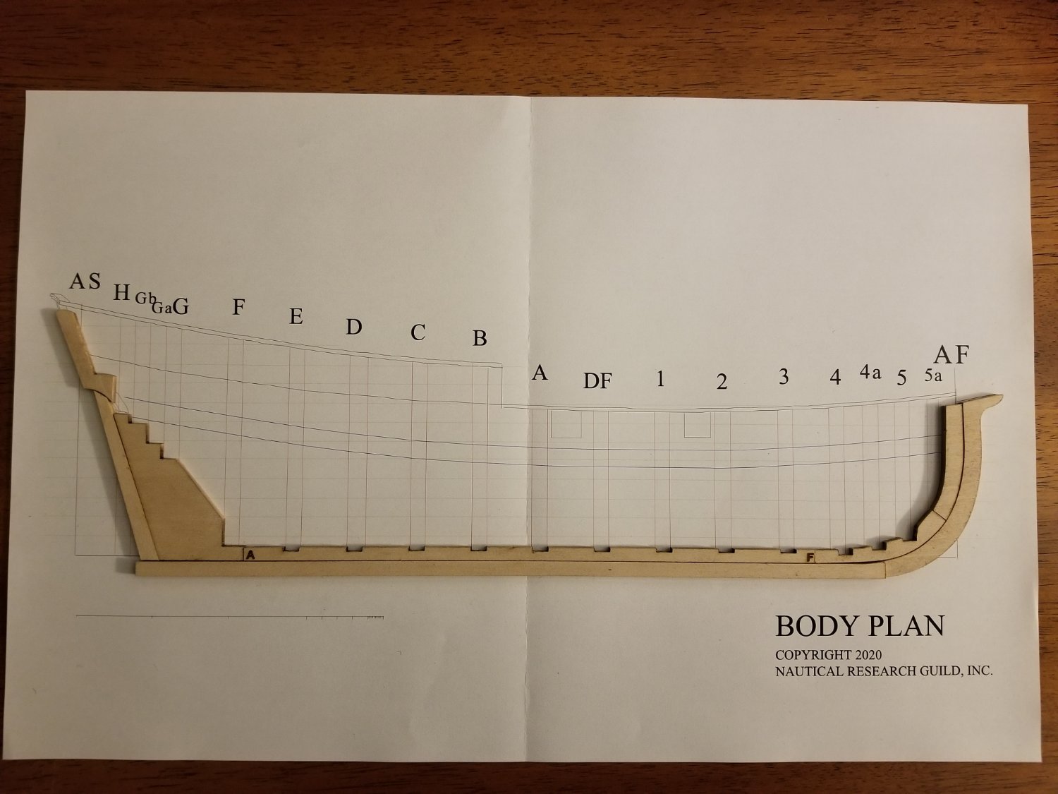
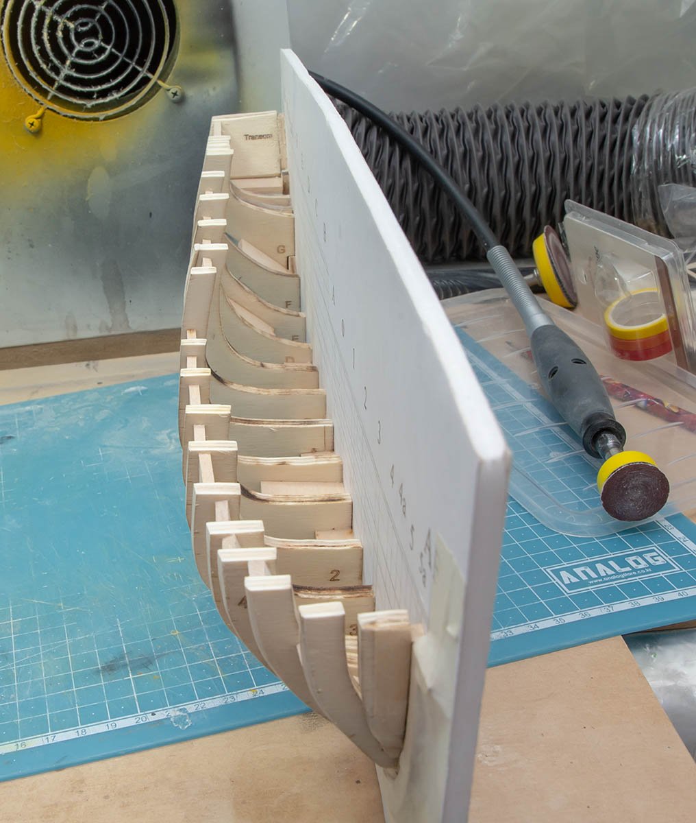
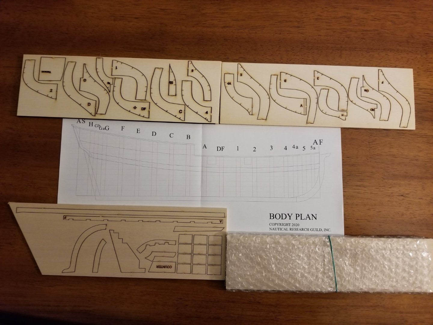
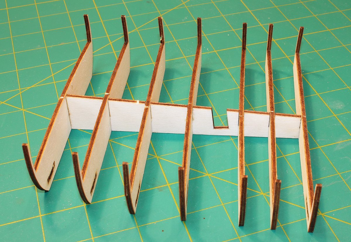
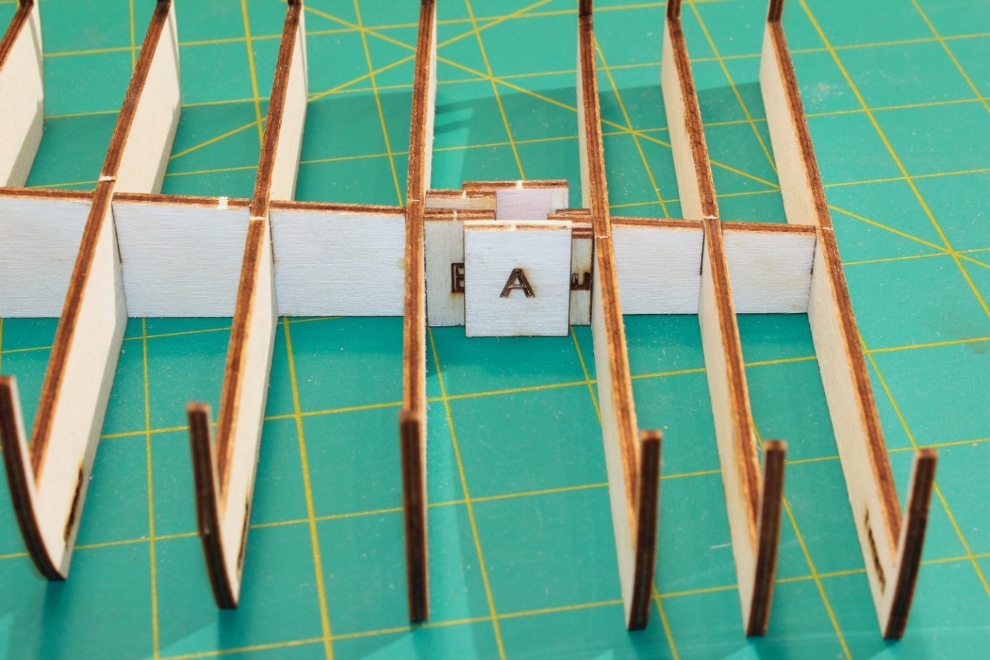
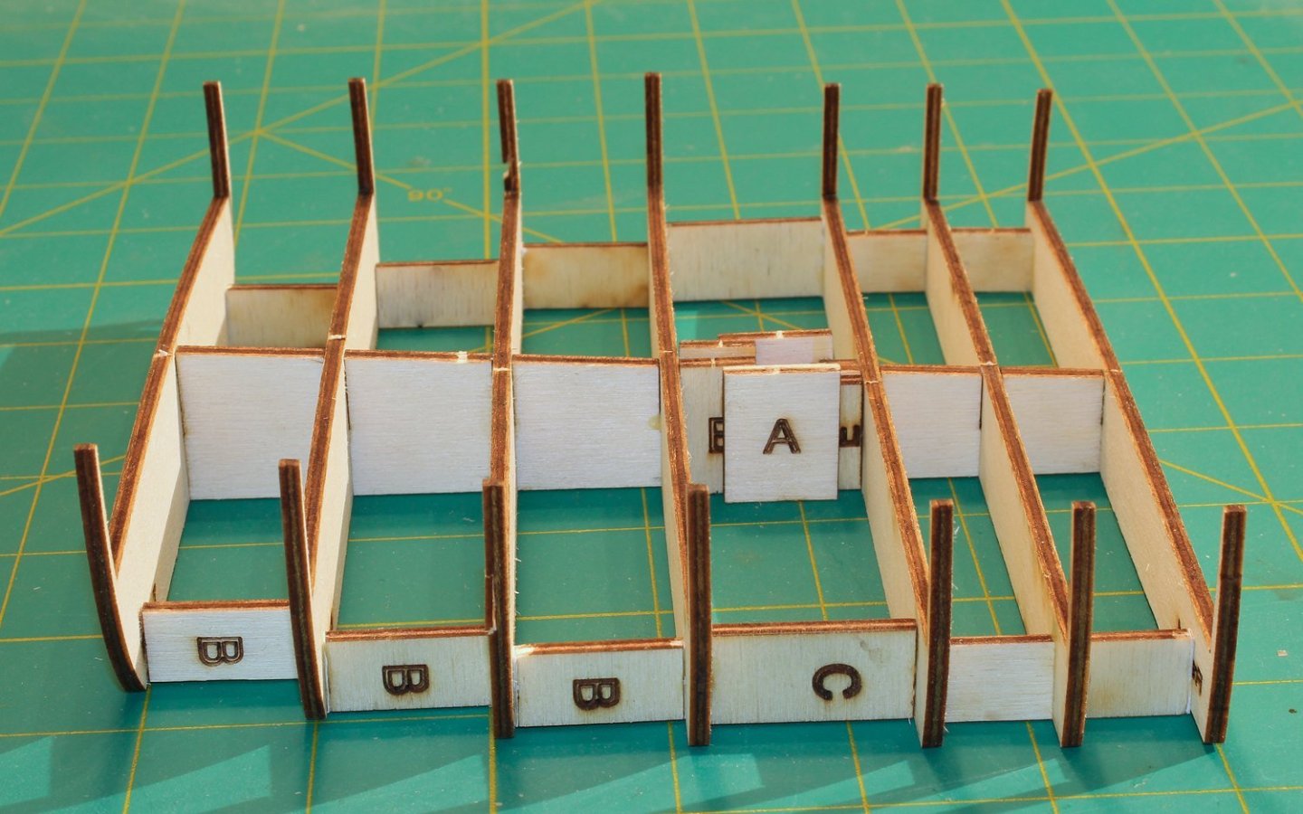
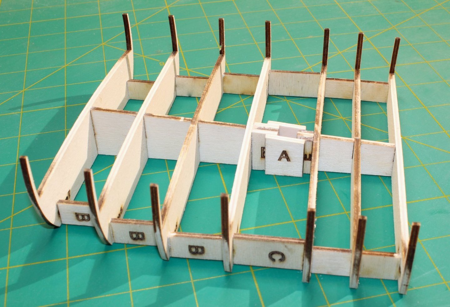
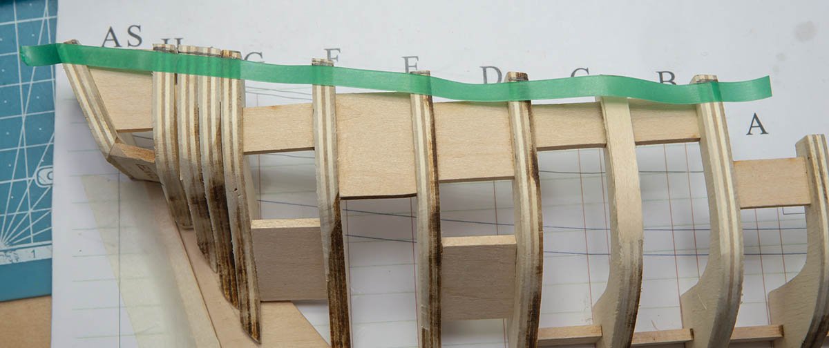
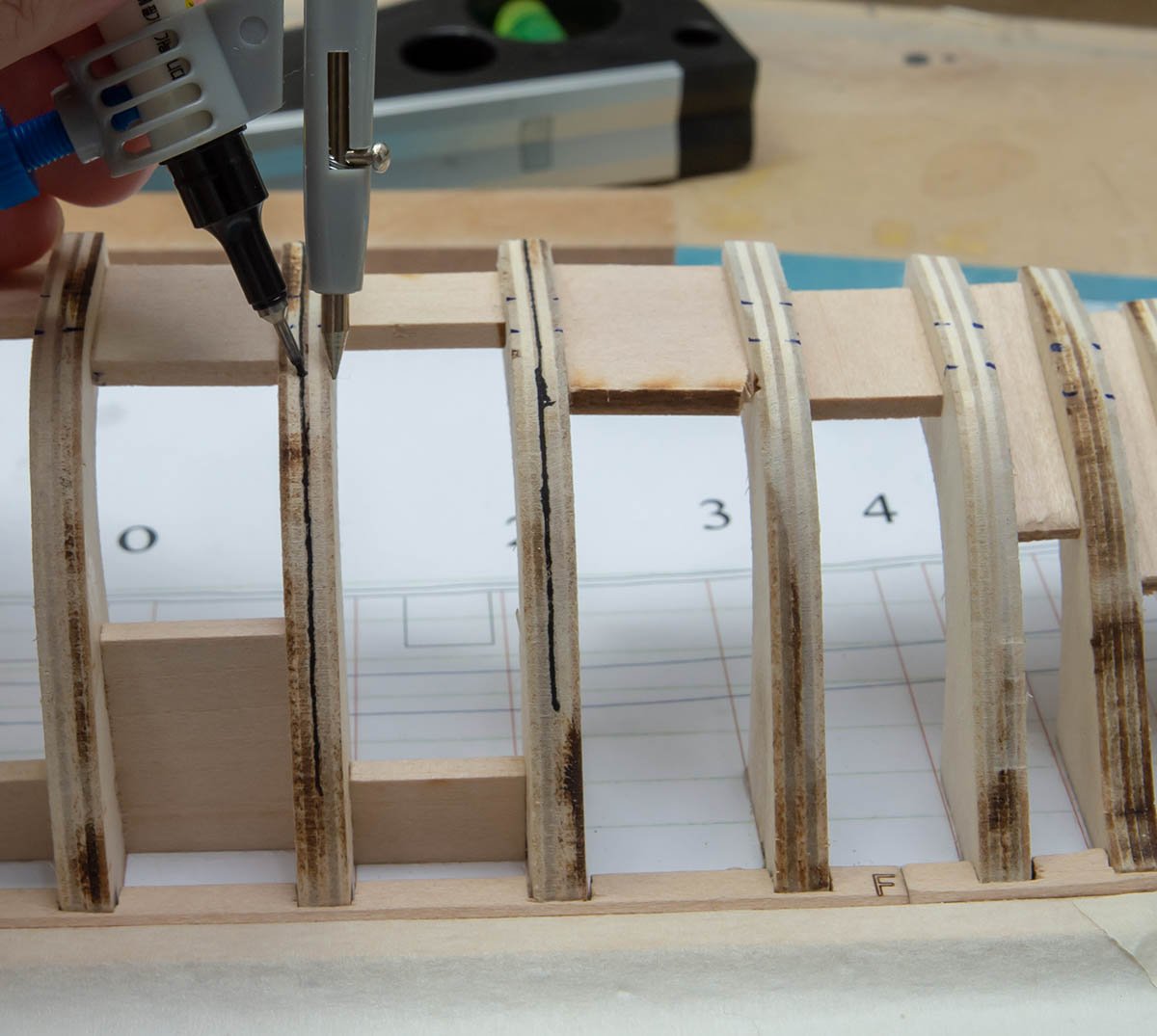
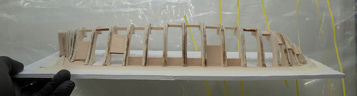
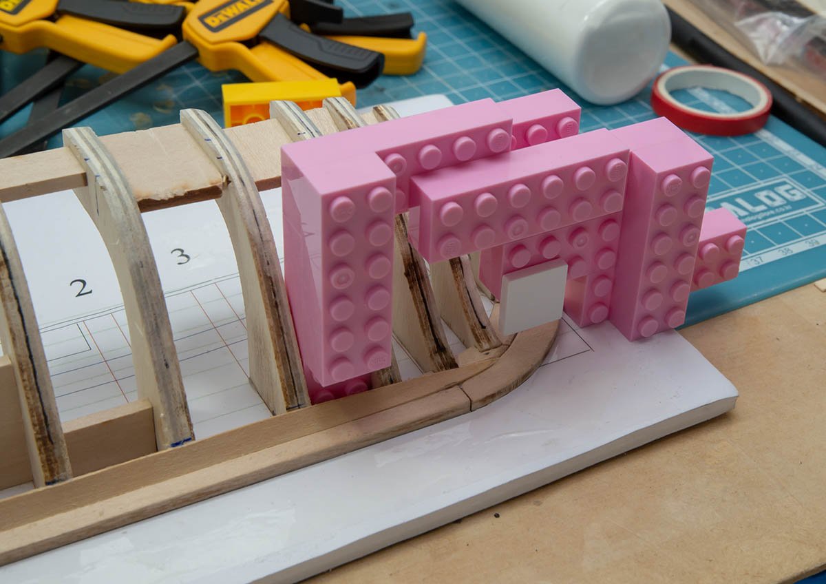
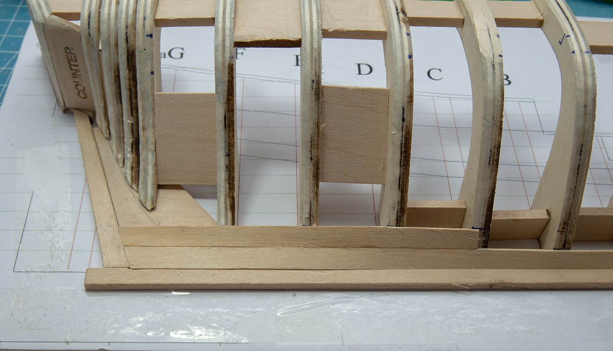
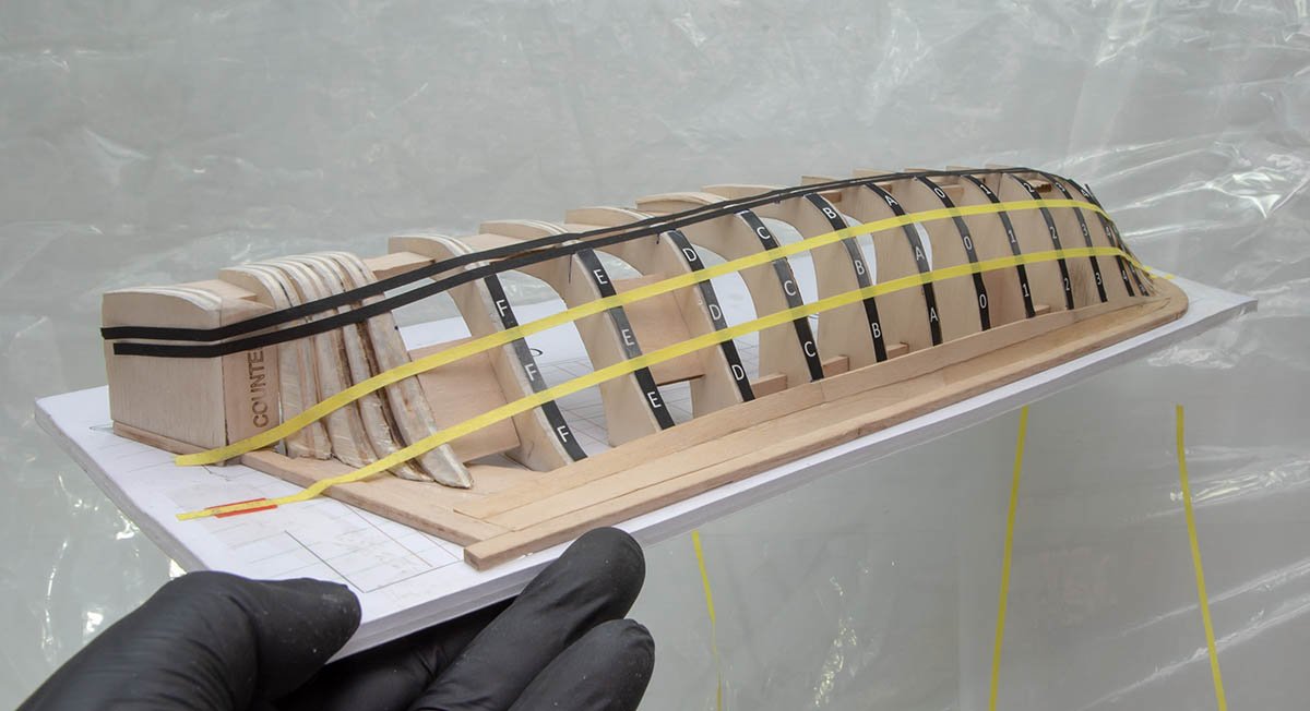
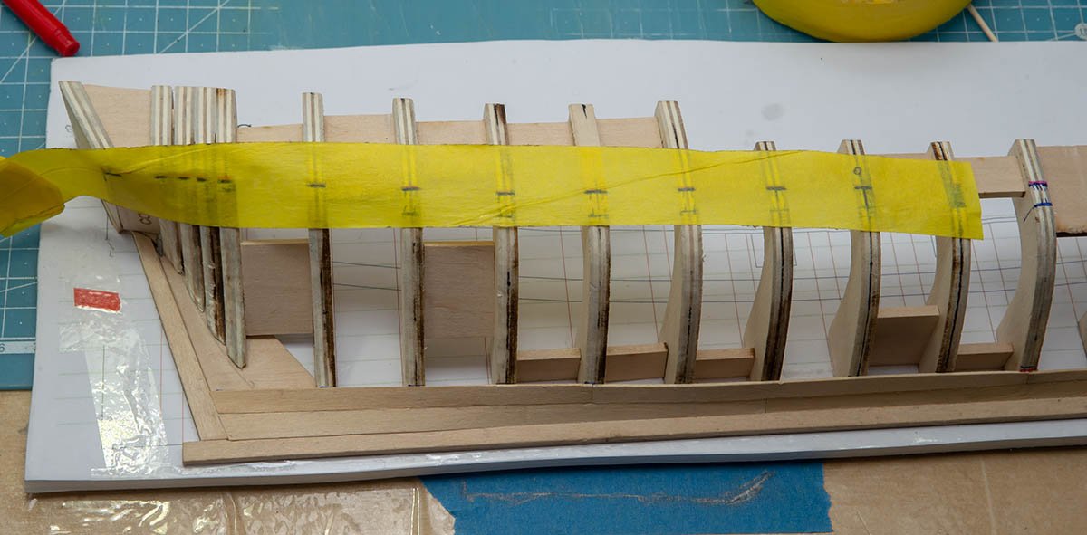
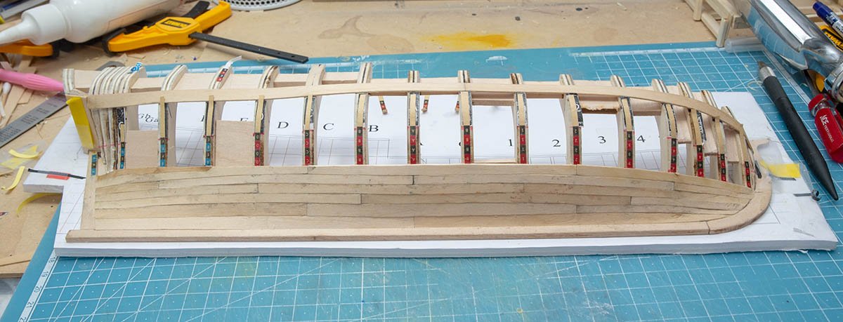
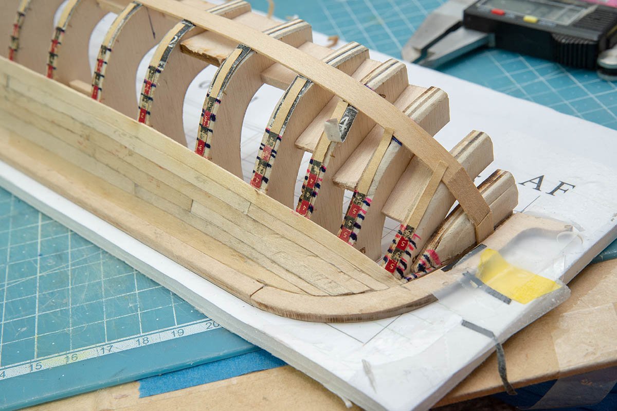
 The NRG is an educational organization, dedicated to providing our members with the knowledge to improve the quality of their model ship building. One of the most common problems model builders have is rigging their model. Kit instructions are poor. Often, the materials provided in the kit are improperly sized or the cheapest that the manufacturer could obtain. We all know that blocks are not square! I wanted to develop a project whose purpose would be to teach ship modelers how to mast and rig a ship without having to build a complete hull. This model is a 1:48 scale cross-section at the level of the main mast of a late 18th century British sloop of war, Swallow 1779. To keep the size of the model manageable and eliminate the need for a building board, the hull is cut off just above the waterline. For the same reason, only the center portion of the lower yard and the lower part of the topmast are constructed. Also, because this is a cross-section, certain lines, such as the stays and backstays, are not included. My emphasis will be on demonstrating techniques to improve your rigging skills. Skills that can be used on your next project. As this was developed as a teaching aid, certain shortcuts and compromises to historical accuracy were taken. Wherever possible, I have used measurements provided by the plans and such authorities as Steel and Lees. I apologize in advance to the master modelers who might criticize my shortcuts. I have kept the use of power tools to a minimum. The only thing that is outside the normal collection of hand tools is a serving machine. The Guild hopes to begin selling this kit in the next few months. The kit contains all the materials required to complete the model. But I always keep my scrap box nearby for those times when a piece of a contrasting color wood is desirable. I will mention those times as the build log progresses. Also, the build log is made up from the best photographs taken from three builds of this model. A sharp eye will notice some differences in the wood color because of that. The hull is constructed in typical plank on bulkhead style. There is a notched spine and notched bulkheads. The laser cut sheet of one-eighth inch basswood ply also contains a template for the top and four types of spacers, A through D. The spine and the frames are assembled as seen below. Frame 1 is installed with the printing facing aft. This gave me the option of painting the exposed bulkhead after construction was completed. The mast fits in the slanted slot between Frames 3 and 4. To keep the mast vertical, support spacers are glued on both sides of the spine. They will be sanded flush to the spine when the hull is faired. To prevent the hull from twisting and to strengthen it, spacers are placed between each frame. The three aft spacers are “B”, the next one is “C” and the two foremost ones are “D”. They are placed close to the edge of the frame for maximum stability. The laser char only needs to be removed from the fore and aft sides so that their surfaces are flat. If too much wood is sanded off, I glue strips of paper onto the edge as a filler to prevent distorting the hull. The hull and deck were faired so there are smooth curves fore to aft. I used a sanding block for this. I did not fair the bulwark extensions (the thin strips of wood above the deck) to prevent them from breaking off. This model has a significant camber to the deck. Sanding sticks help getting into the corners. You can see that the mast supports have been sanded down to match the height of the deck. Next up is planking the hull.
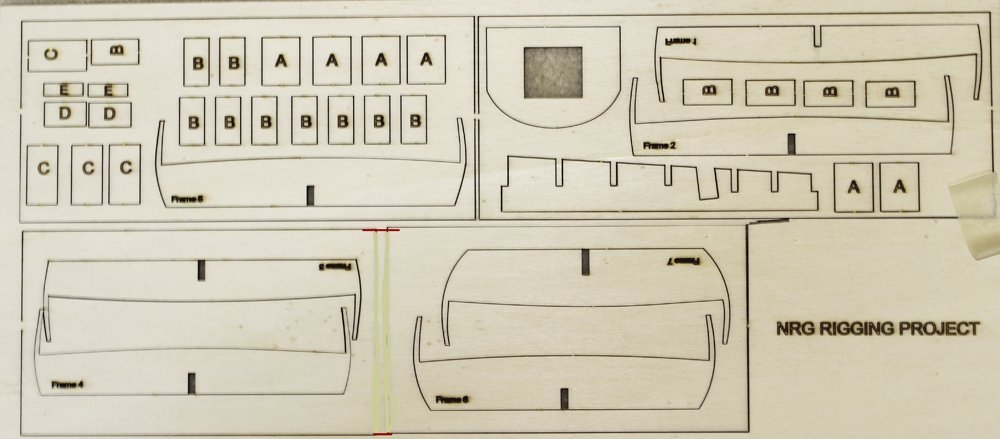


- 31 replies
-
- 42
-

-
-
- rigging/masts
- NRG
- (and 1 more)
-
 I've decided to pause my other projects since as a result of my stroke my memory has failed in some areas. Mostly it's working but some things are gone forever like "how to plank" while other things are coming back to me. So, after much thought, I've ordered the NRG Planking Project. I've downloaded the manual and am reading through it. The kit should be here this coming weekend.
- 4 replies
-
- 14
-
-
- half hull
- half hull planking project
- (and 1 more)
-
 After taking my Bluenose as far as I wanted I decided it was time to learn proper hull planking. I ordered the kit ( https://thenrgstore.org/products/half-hull-planking-project) from NRG some time ago and will spend the next week or so gathering what I need for this build. I will also be reviewing the various build logs of other other shipwrights to gain further insights. Since I now have some experience I've decided to upgrade my material to Boxwood rather than using the Basswood that comes with the kit. Hopefully I would ruin too much of it. 😆 Any advice or suggestions from those who have built this kit is always appreciated! Dave
 -
 In dire need of planking & spiling practice before tackling the next project, I was so pleased to come across NRG 18th-Century Merchantman Half-Hull Planking Kit . Actually, this project was started just after last Christmas as a present (to myself) and is now just about finished except for the mounting. I knew I would be dragging this one out because I would be experimenting with different wood, adhesives, wood bending, finishing, etc. and wanted all that to be done on one model rather than one model at a time. That being said, there would be large gaps in posting the log of a relatively small kit. Mike
-
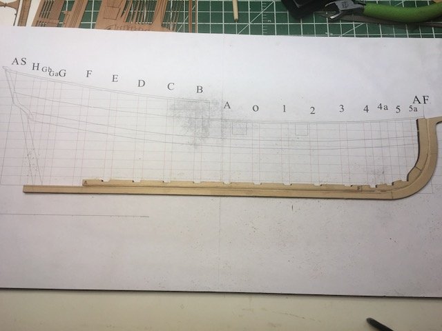
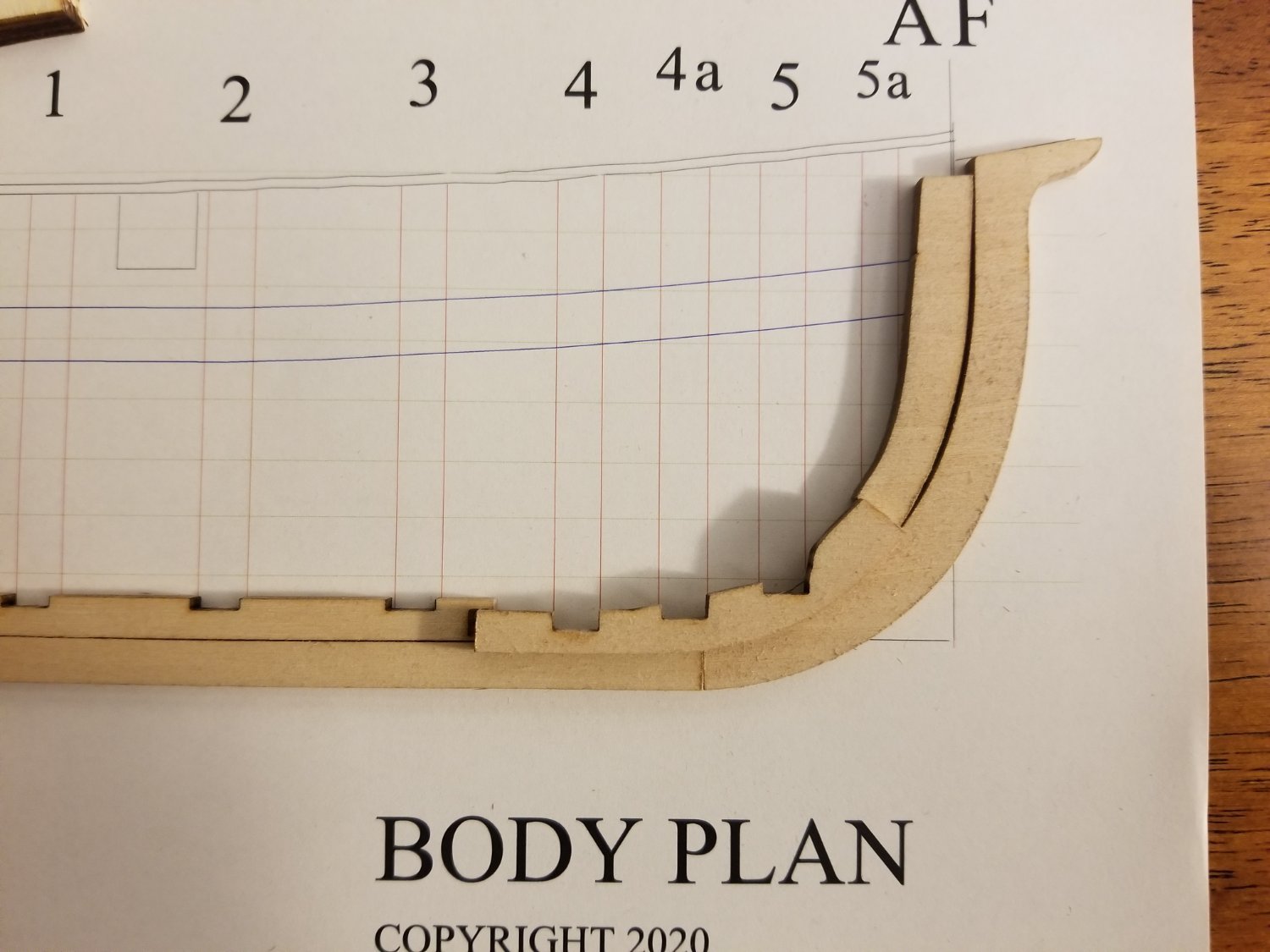
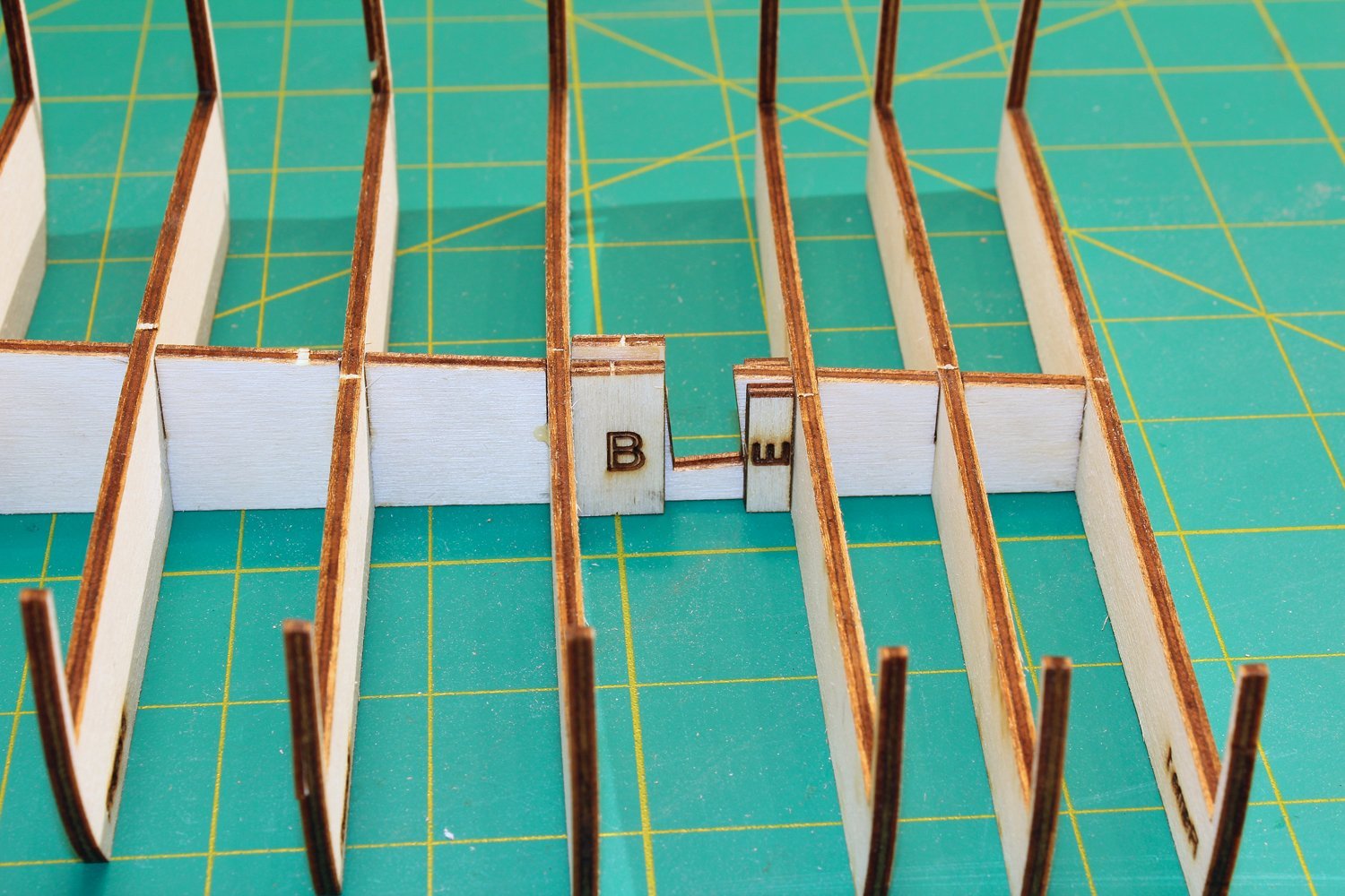
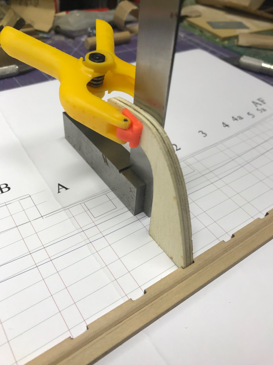
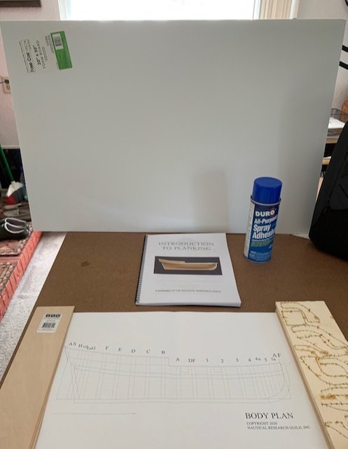
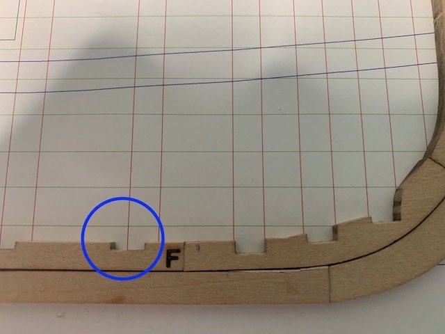
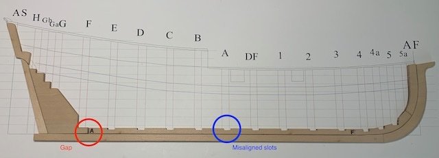
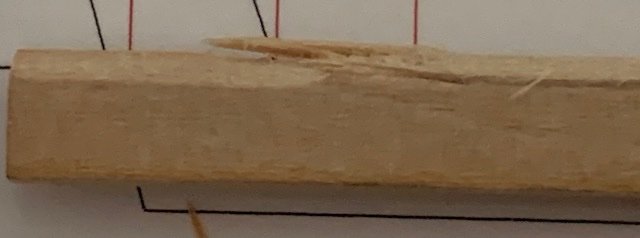
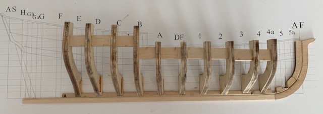
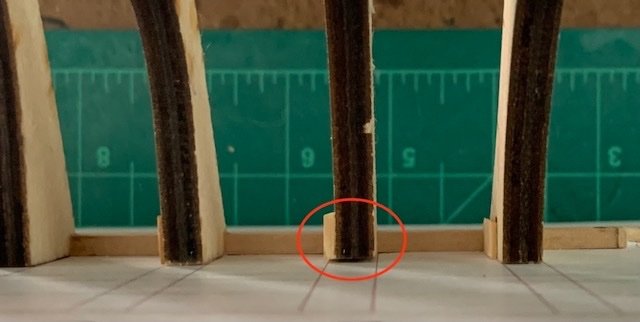
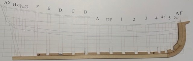
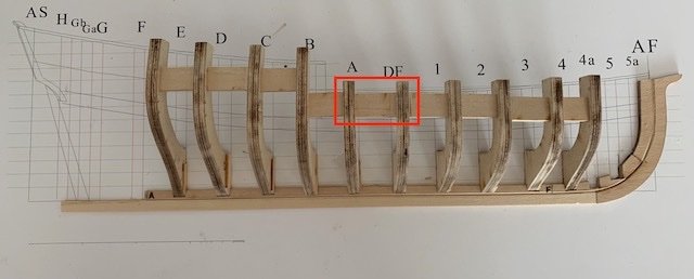
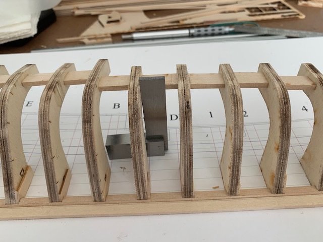
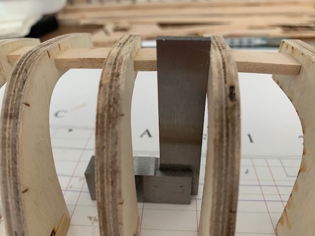
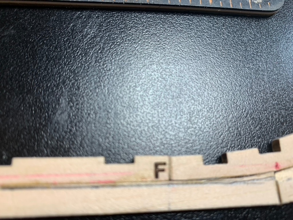
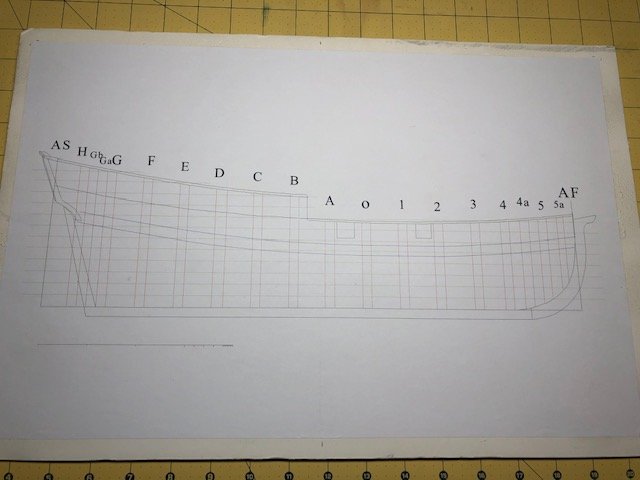
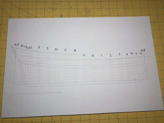
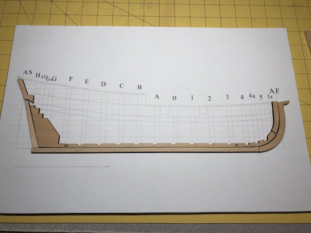
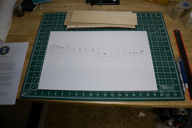
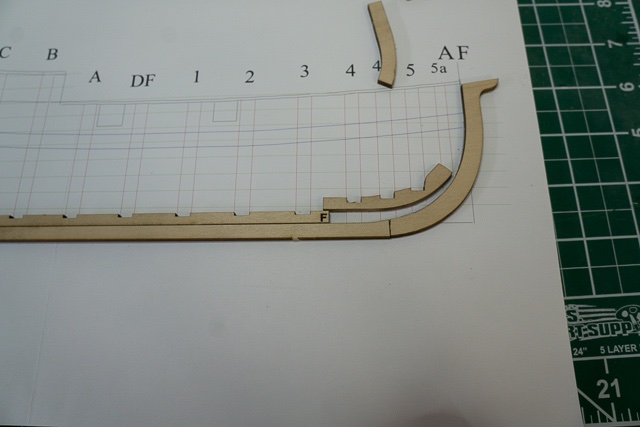
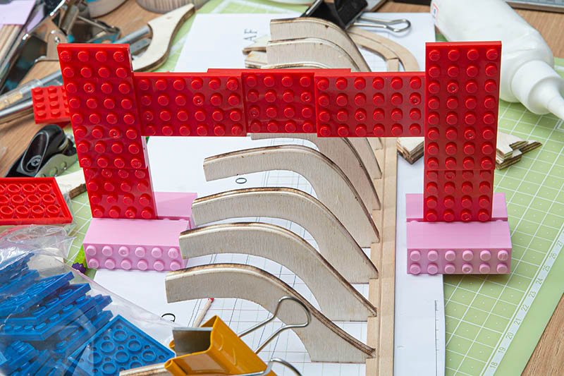
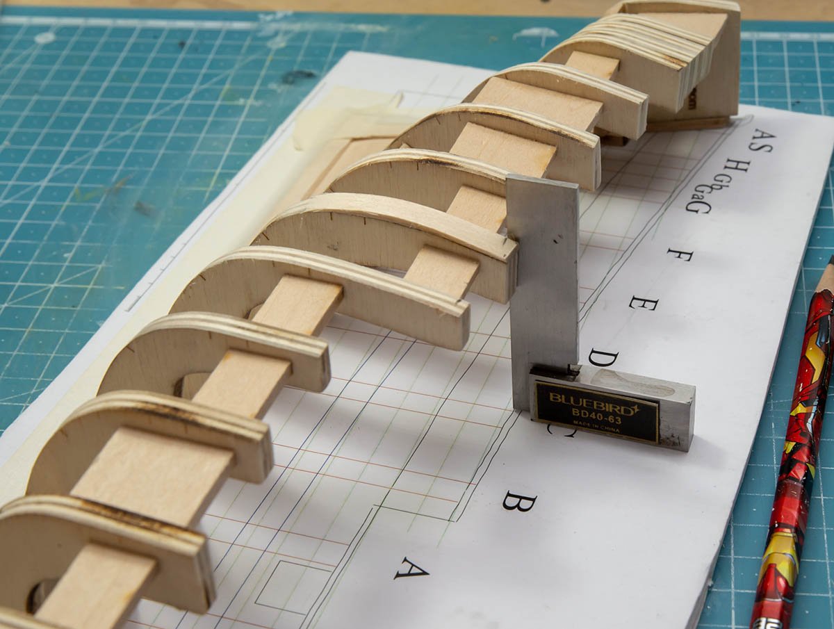
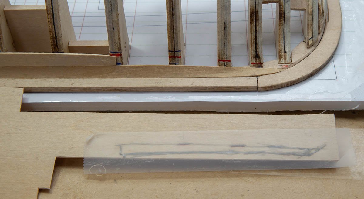
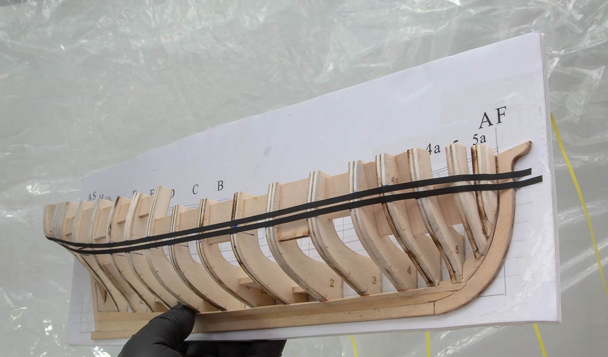
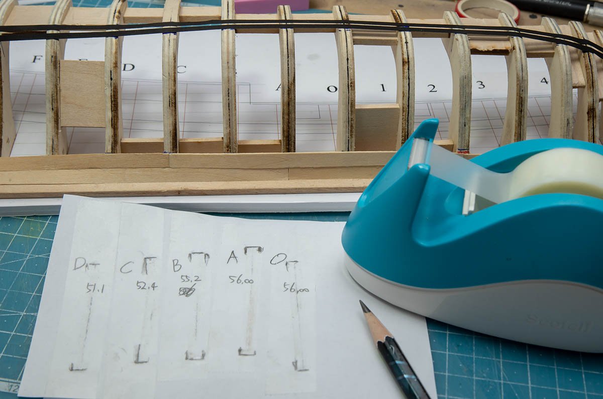
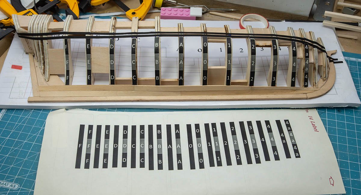
 While working on the planking for the Albatros by OcCre, I realized I needed more instruction on planking. So I joined the NRG and ordered the planking kit. Now, several months later and after finishing the Albatros, I’ve begun. Bookmarks My first step was to bookmark all the Half Hull Logs. After looking at the logs, I eliminated the ones I didn’t think were useful. (No disrespect intended.) Print and bind The next step was to print and bind Toni’s instructions. After printing the manual on my laser printer, I took the printed sheets to Office Depot. It was only a few bucks and I was surprised how fast the binding took; Literally, it took two minutes. Now I was ready to start. Unfortunately glueing the plan to the poster board turned out to be much more of an effort than it should have. First, the spray adhesive was partially clotted. I carefully cleaned out the nozzle but that didn’t help. The spray can had been lying on it’s side in a drawer for years and the adhesive came out in clumps no matter what I tried. So off to the store to get new adhesive. Next when I was attaching the plan to the board, the plan slipped off my fingers and resulted in bubbles. I emailed Mary at NRG about getting a PDF to print. Amazingly, she replied within an hour with a PDF file. As the plans are larger than my printer’s capabilities, I debated whether to print two sheets or go to the copy store. I decided that it would be less error prone to glue down a single sheet than sheets. Subsequently, I went online and uploaded the PDF to the local Office Depot. A couple of hours later, a printed copy. My second attempt to attached the plan to the poster board went perfectly. Starting putting things together When I aligned the fore keelson slots, the slots did not match up as shown in the picture below. I removed some material from the fore keelson to align the first slot. After removing the material to align the first slot, a gap was created between the keelson and the dead wood. I then added a filler piece. As you can see, a number of slots were not aligned with the plans. Whether the misalignment was a problem in the laser cuts or the printed plan made from the digital file was slightly stretched, I don’t know. Regrettably, I threw the original printed plan away. No matter the cause I decided to fix it by cutting the aft end of each slot to align with plans. Then when installing the bulkheads, I could add a filler piece. The rabbet I wanted to create the rabbet using a chisel to develop my skills. I practiced carving the rabbet on a piece of scrap wood. Thinking I had it down I proceeded to the keel itself. It didn’t go so well. Fortunately, the local art store carries basswood and for $1.08 I had two pieces of the same size, albeit without the hump. After adding the hump, I opted for sanding the rabbet. Even if I had a higher level of dexterity, I think that sanding would have been the better choice to begin with given the tiny size of the rabbet on the keel and keelson. For the stem and stemson, I used a combination of a chisel and sanding stick. Deepening the slots in the keelson I found it difficult to not damage the poster board. My only concern about this was how it might impact the frame alignment. This didn’t turn out to be a problem. Placing the bulkheads As mentioned earlier, to align with the plans nearly every slot was too wide. To compensate, I glued filler pieces to most of the frames. Frame alignment error 1 After installing each frame and starting to install the spacers, I noticed one frame wasn’t lining up with the others. On closer inspection, I had installed it at an angle. Frame alignment error 2 I was glad I was using PVA glue so I could remove the frame. I may have been a little too impatient because after removing the frame, a small and critical piece of the filler broke off. But perhaps it wasn’t my impatience, as the filler piece was flimsy wood. I replaced it with a stronger wood. Hopefully, I’ll remember to used better wood for filler pieces in the future. Most of the spacers required removing some of the material. However, between frames A and DF, and frames DF and 1, I had to add shims. With the machinist square the frames look vertical. However, when visually sighting these frames, it looks like frame A is not vertical. I think I’m going to remove frame A and redo it.
- 17 replies
-
- 11
-
-
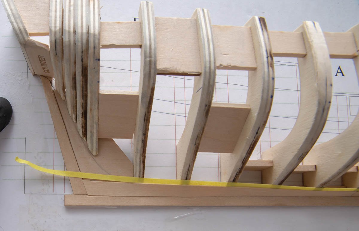
 Hey guys, So.. due to a case of COVID I finally made a start on my half hull; it's the first time I've ever done anything like this so I feel like it's going to be a little bit rough and a steep learning curve... But we have to start somewhere right?? I came across MSW a year ago while I was looking up some techniques for making a ship in a bottle which I was whittling at the time, & then I discovered this half hull project. I decided to give it a go because it appealed to me that it's the same basic techniques you would use for spiling on a full size vessel & I'd like to learn it. Any help & tips are always welcome! I'll back date the next couple of posts to get my log up to date. Happy Monday everyone.
 -
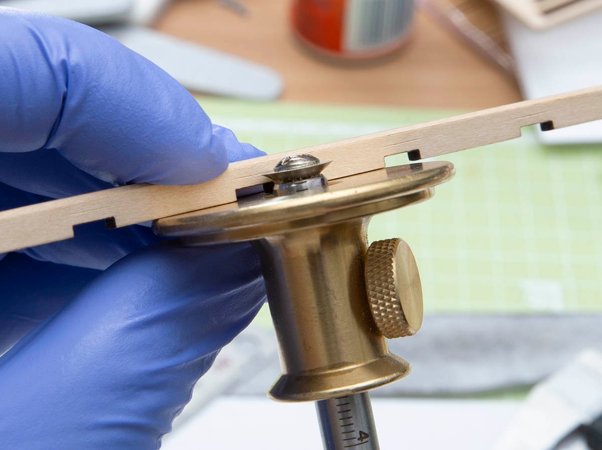
 While I wait on some replacement items to finish my San Juan Felucca build, I decided to crack open the half-hull planking kit and get started with this build log. A piece of quarter inch foam board from my wife's craft room and some spray adhesive and the build board was ready after setting overnight. The spine pieces took some care to get released from the sheet as the cut did not go completely through the wood. I tried both scrapping and sanding to remove the laser char from the surfaces to be glued. I found that using an old blade to scrape the chare worked best on the curves and kept the edges straighter than sanding, but sanding worked well on the flat edges.

-
 This is my next project after completing the first three kits in the Model Shipways model shipwright series. Each of those kits provided good experience and instructions on planking, I clearly need more practice though , and hope to learn how to lay out the planking on the bulkheads and how to shape the planks. Those skills were not needed in the shipwright series since the planks were all cut to the correct shape. This kit looks like a great way to learn more. There are many other build logs on MSW that I am sure I will be referring to for help as I go along. I managed to hunt down the spray adhesive and foam core board to make the building board and have started removing the char form the parts and seeing how it all goes together. I have some scraps of basswood left over from other kits and I think I am gong to make copies of some of the pieces to practice cutting the rabbet a few times to reduce the chance of messing it up too badly . Dan
-
 While scouting the different build logs I came across a NRG Half Hull Planking Project by T Livine and decided that I should get this and learn the proper technique. After receiving this tutorial kit I did my usual kit inventory and all was well. The bulkheads are thicker than what is normally found in the kit and that in itself makes the fairing (shaping) of the hull easier AND it gives more surface for the planks to adhere to the bulkheads. So without further ado, I begin. Pictures will be aded at the end of this segment. Following the instructions I attached the the plan to the building board (1/4 inch foam board) purchase from our local craft store. Then I carefully removed the parts for the beginning of the build. The stem post, keel, keelson, stern post etc. and dry fit them all on the plan. The slots in the keelson for the frames were cut a little narrow which allowed for a better fit after some slight sanding. Then came the first of my worries...the rabbet. Kits usually don't have nor do they mention a thing about cutting the rabbet. I thought of trying it on my Mayflower build but not knowing enough I refrained from trying its until I learned the correct way. This kit was great at teaching the proper way to cut the rabbet. I wish I had known about this kits for my other builds. After reading and re-reading the method in the tutorial, I carefully marked the rabbet and used a small file to carve it out. I think I did a fairly good job of it. I then removed the frames from the supplied sheets and sanded off the char so the frames could be glued. Did you know that glue doesn't hold well on the areas with char from the laser cuts? I didn't! Starting with the first three frames, I had to file just a little off of one of the slots in the keelson for the frame. It took me three days to get all the frames mounted to the keelson and now I have to add the supplied spacers between frames for stability and strength. Next thing will be to mark the bearding line and remove the deadwood below and aft of it. Well stay tuned. I'll add the missing photos when I figure out why they won't post here. Until next post....build on! Dry fitting the keel, keelson and stem post. Marking the Rabbet on the Keel and Keelson After twisting my knee working outside, I finally got back to the planking tutorial. I tackled the bearding Lind, deadwood nd most of the remaining frames. I still have a few remaining frames and the transom to take care of before I start fairing the frames. This time I won't have the false deck to help me get the shape correct but this IS a tutorial right! These next photos are where I am in the build now. Somehow the last photo wants to upload upside down.
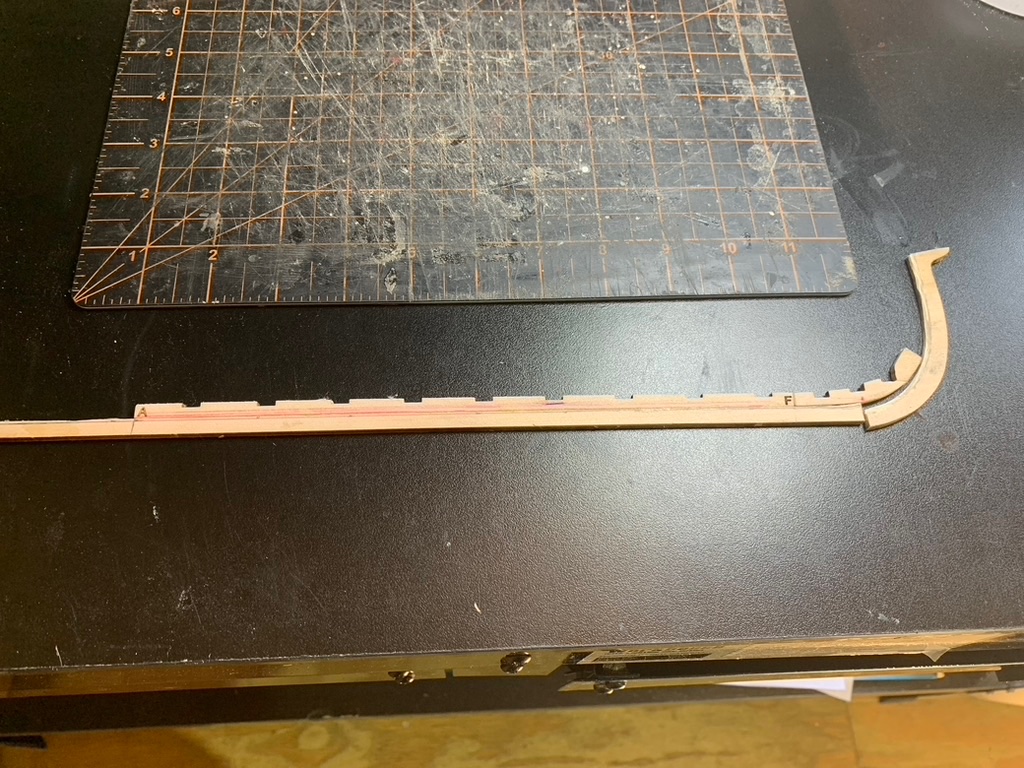


- 4 replies
-
- 7
-
-
- half hull planking project
- NRG
- (and 1 more)
-
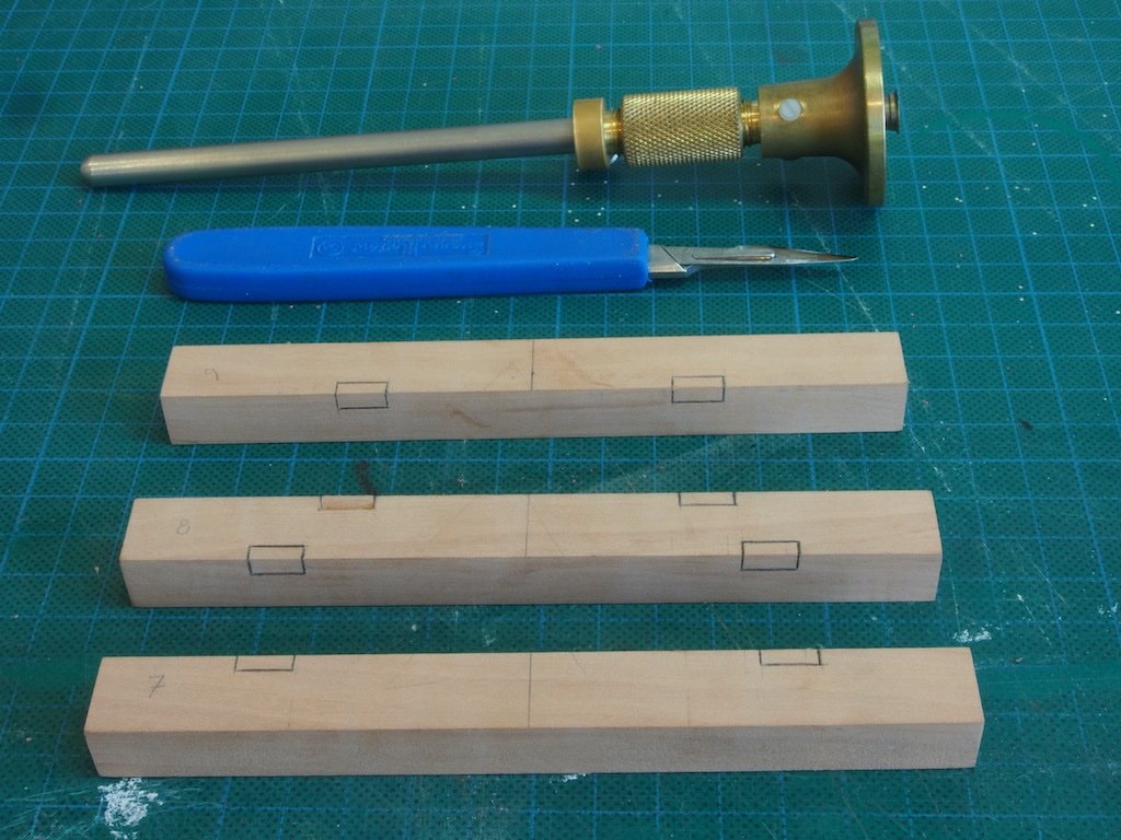
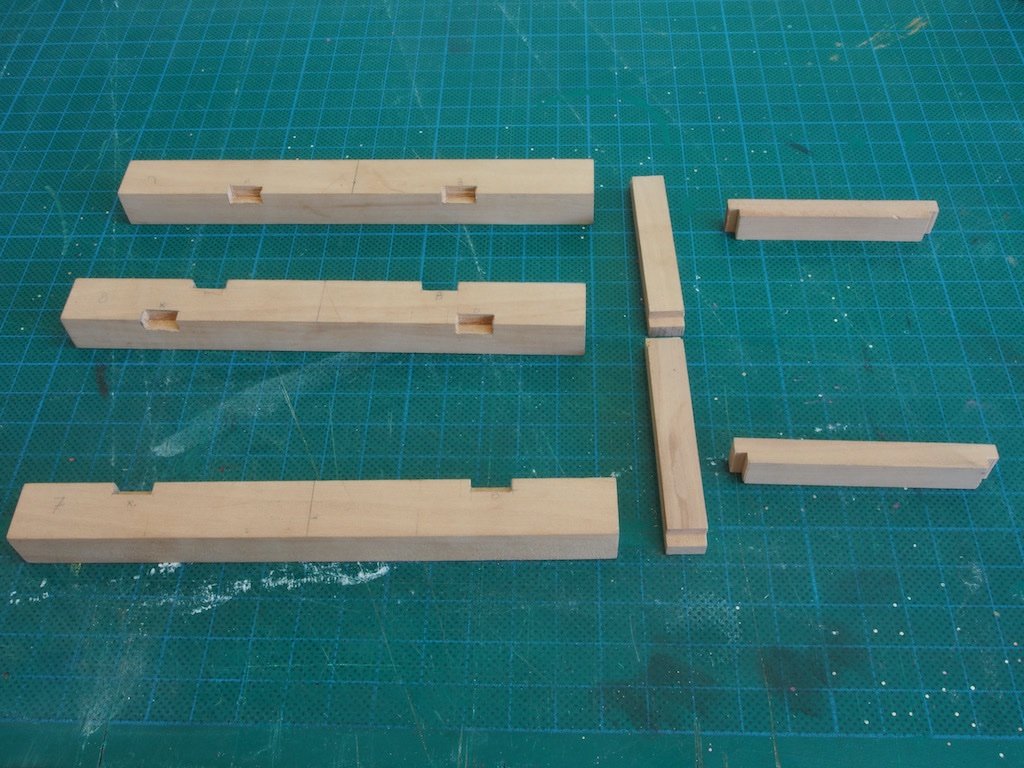
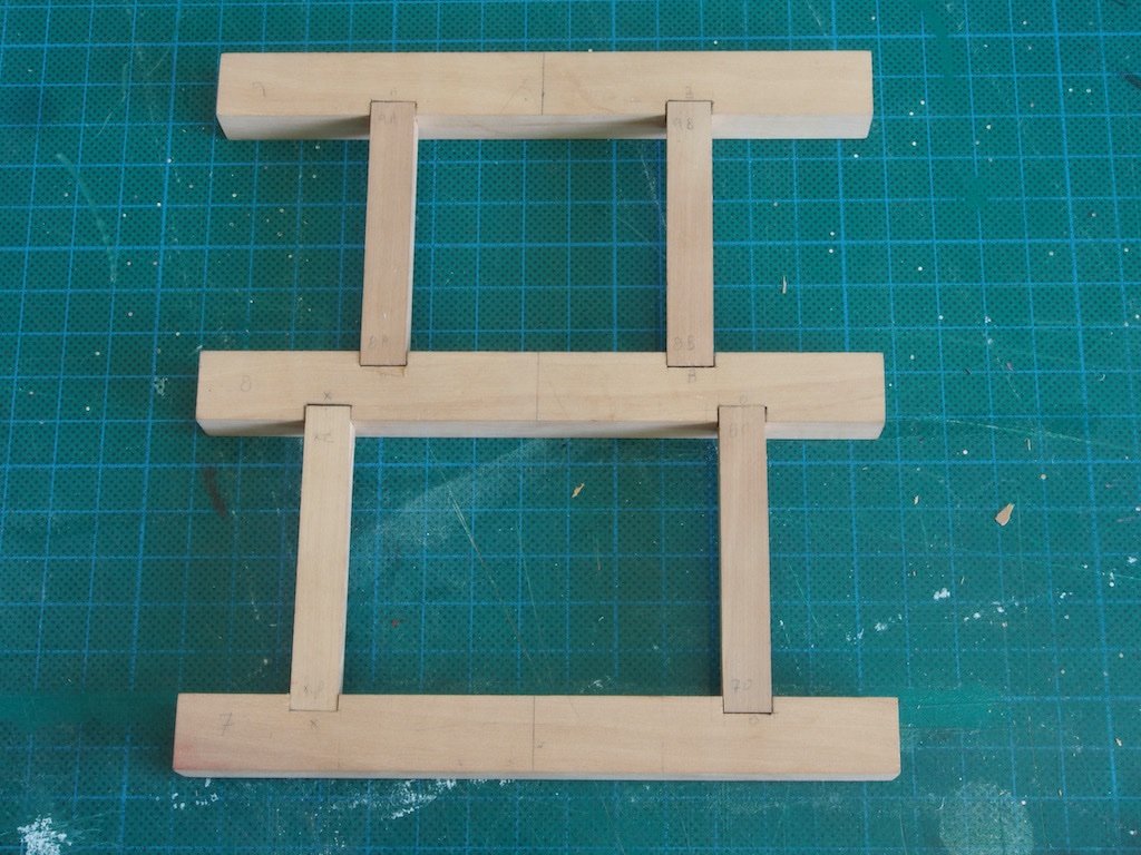
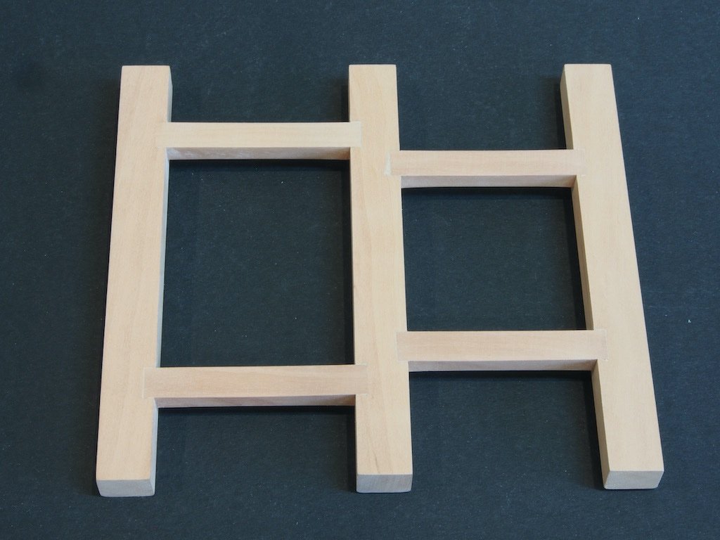
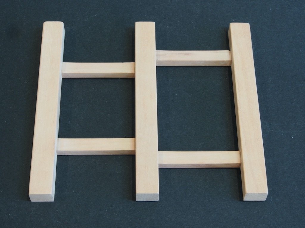
 I am between modelling projects at the moment. Some time ago, I managed to acquire some additional stocks of very nice modelling timber from Jeff Hayes when he closed down his Hobbymill operation, so I decided that the Capstan model project from the NRG would be a good use for some of that stock and would give me a nice entry back into the scratch building side of things. Plans and instructions are by Toni Levine. As I have all of the toys, I decided to go straight for the Advanced version – hopefully, I won’t regret that decision down track! I will be building at a scale of 1:16, as Toni did in her version. I have downloaded all of the instructions and plans, ensuring that I had the amended version. The first challenge was to create a cutting list to determine the stock sizes I would need. As Toni has provided drawings with full size measurements in decimal inches, I decided that the easiest approach would be to create a spreadsheet to do all of the conversions for me. As my lathe and mill are both calibrated in metric units, I set up the spreadsheet to spit out measurements in both scale millimetres and scale inches (both decimal and fractional). I then went through all of Toni’s drawings and entered in the full size measurements and let the spreadsheet work it’s magic. While I was at it, I made a separate part of the spreadsheet a simple converter to use for other measurements as they crop up. This is proving to be a very useful tool, so I’ve attached it here in case anyone else might want to use it and save themselves from having to duplicate the effort. I take no responsibility for the accuracy of the information!!! Capstan Parts Scale Converter.xlsx With that task completed, I then went through my stash of timbers and selected some pieces that were close to the right thickness and processed them through my full size drum sander until I had all stock material to the appropriate thickness. I’ll be using Pear for the Beams and Carlings, Red Heart for the Hatch Coaming, and Box for the majority of the rest. I may use Red Heart for the Capstan Bars also, but I’ll reserve a final decision on that until I reach that point. Toni’s Practicum is very well laid out and not only identifies parts by part number but also groups these together into sub-assemblies. This is a really useful inclusion (thanks Toni 😊). Although the sub-assemblies can theoretically be completed in any order, I will follow along in the same order that Toni has used – I figure that way there is less chance for me to screw it up. The Deck and Hatch collectively make up Assembly 100. This comprises sub-assemblies 101 (Grating), 102 (Hatch), 103 (Deck) and 104 (Capstan Step). We begin with the Deck. Deck (P/N 103) Although I will need to use metric measurements when it comes time to use the lathe and/or mill, for the most part it is more convenient to work in fractional inches, simply because of the way the scaling works out (eg 1/2" vs 12.7mm). My spreadsheet gives me the scale size to the nearest 1/16 inch (although I can check against the decimal inches (thousandths) if required. A glance at the spreadsheet tells me that the Beams are made from 1/2" stock and the Carlings from 9/32” stock. These were cut to final length and width on the Byrnes Saw. The Beams were then numbered and marked with a carpenter’s triangle to ensure correct alignment before being arranged in my magnetic holding jig for marking out. I first marked the centreline and then laid out the mortices from the centreline. Markings were made lightly in pencil to begin with, with the inner edges of the mortices being defined from the measurements in the drawings, and the outer edge defined by placing the actual Carling on the beam to get the exact width. The marks were then transferred onto the vertical surfaces and a knife used to mark all cross-grain lines, while a marking gauge was used to mark all along-the-grain marks. This gave me some very well-defined layout lines. (I went over the cut lines in pencil just for greater visibility). The mortices sides were then cut using a razor saw (in much the same way as one would cut the sides of a half-blind dovetail) and the remaining waste removed slowly and carefully with a full sized very sharp 3/8” chisel. The tenons were cut on the Byrnes saw using the sliding cross-cut table and a stop to ensure that all tenons were exactly the same size. I had one very minor “oops” with the chisel – see if you can pick it. Here is the result: Once satisfied with the fit, the pieces were glued up. I was reasonably happy with results. I then made up a mixture of pear wood sawdust and diluted white glue and rubbed this over the joints and allowed it to dry overnight before giving it all a final sand with 240 grit today. As per Toni’s instructions, I also gave the underside edges of all Beams and Carlings a very slight round-over. Here is a shot of both the upper and under sides ready for the next step: The Capstan Step will be next...
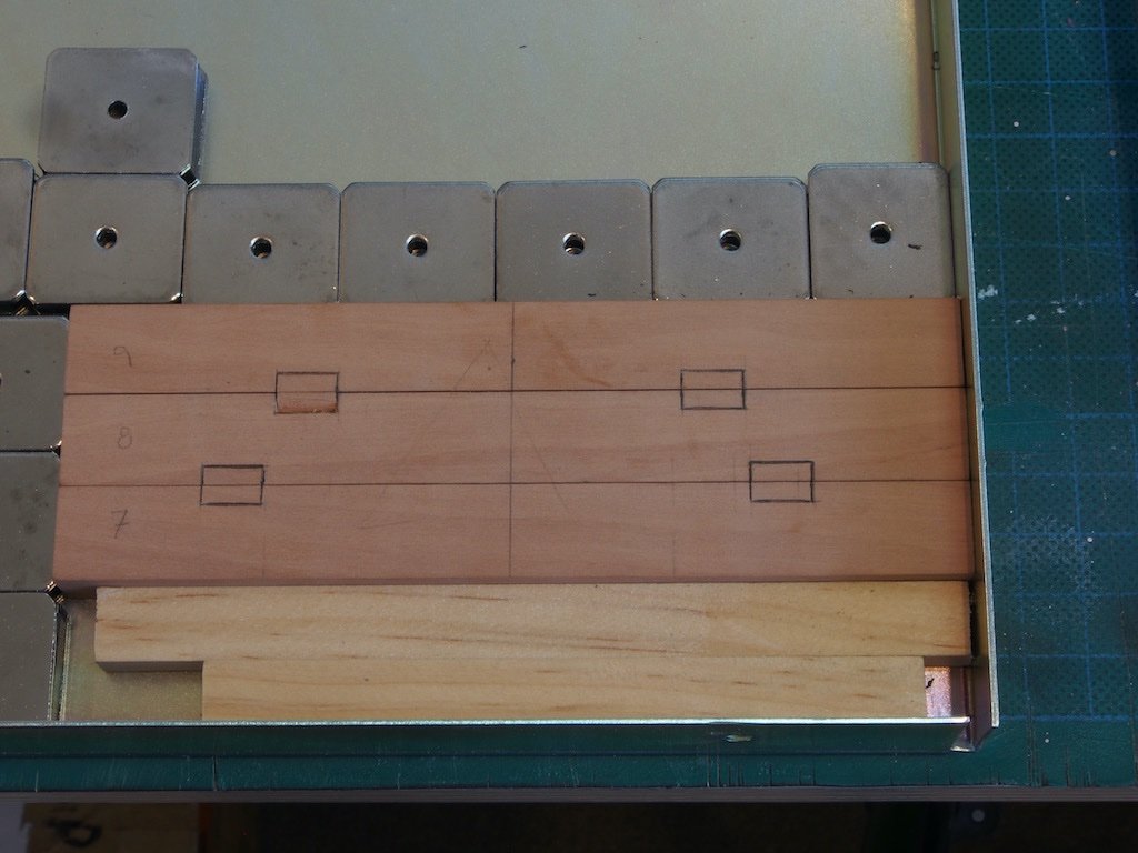
- 43 replies
-
- 12
-
-
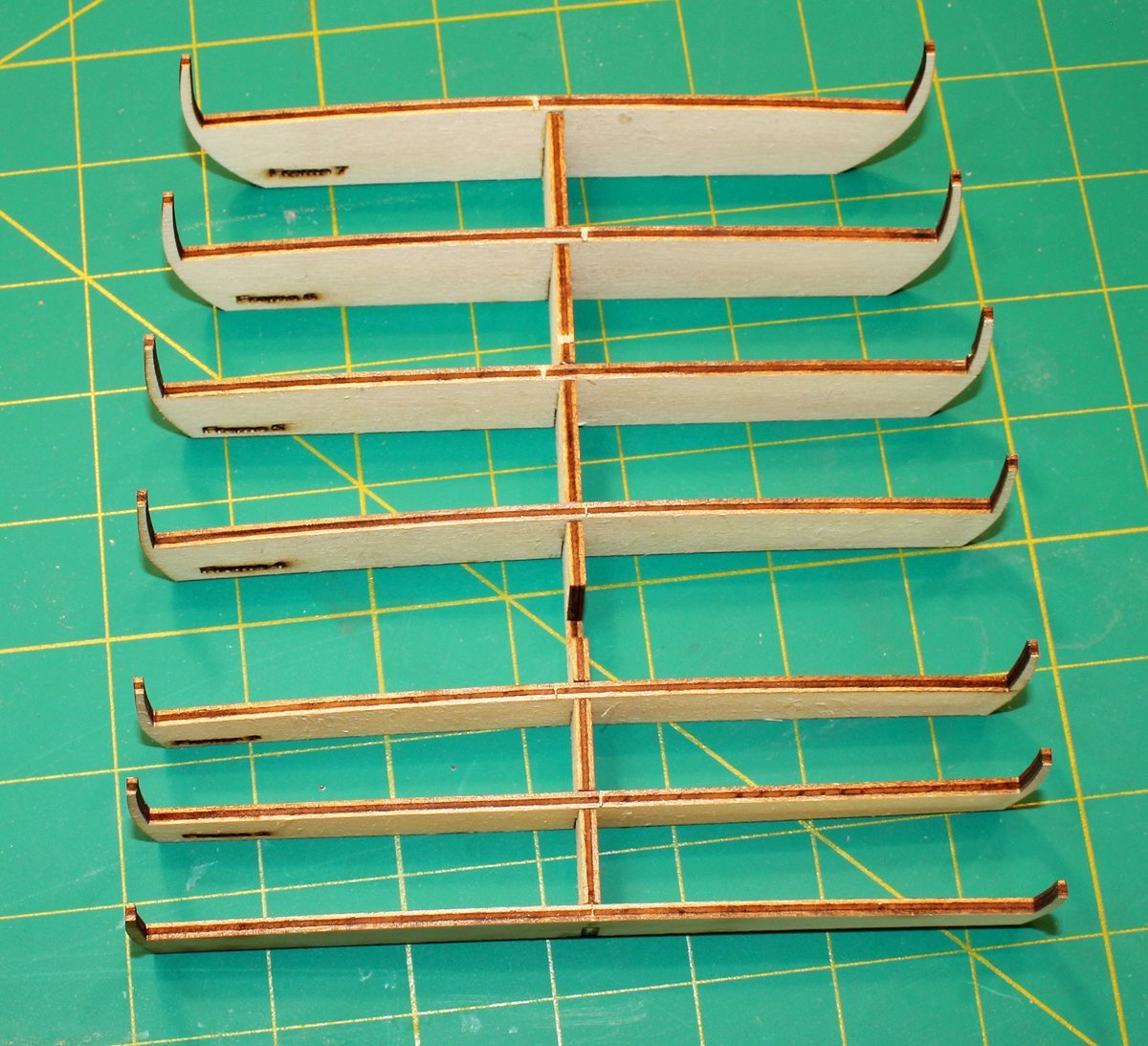
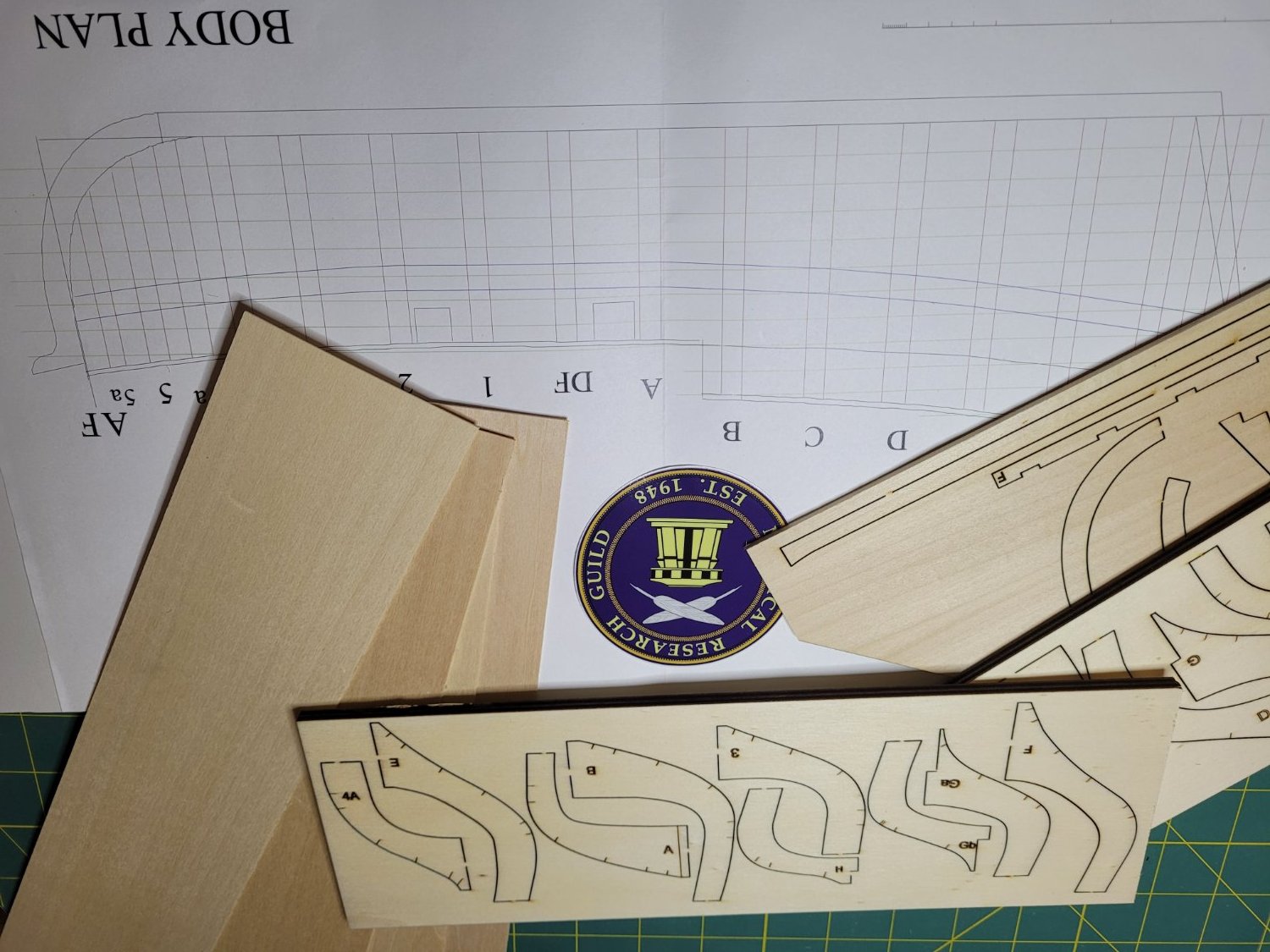
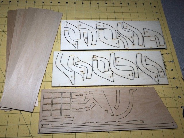
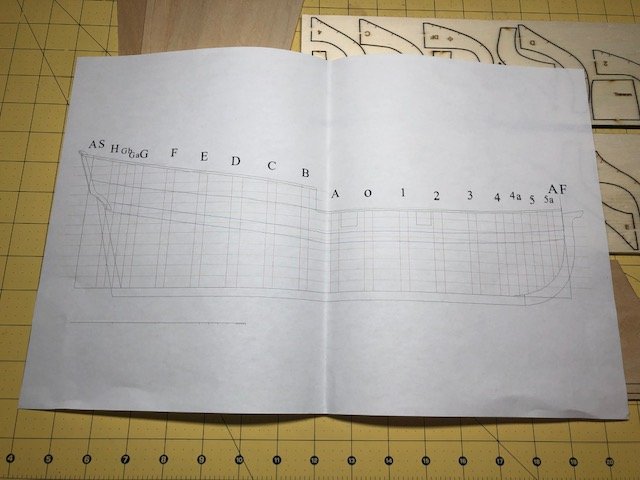
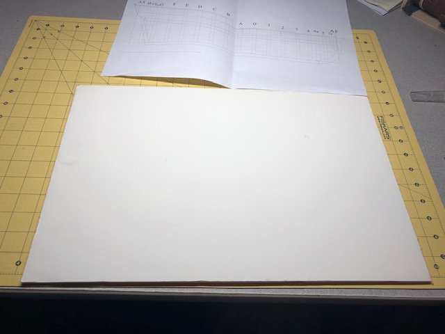
 Hi all, This is my first build log. I didn't discover this site until I was nearly finished with my first build, the HMS Terror. I am planning to post pictures of the Terror in the "Completed models" section. A quick introduction... I am new to the hobby with about one year of experience but that one year has been a lot fun and a lot of learning. I am really diving in and am very interested in making historically accurate models. My next project, AL's HMS Bounty, is one that I plan to do a lot of kit bashing and hopefully producing a historically accurate model. I am still a working guy and I find time in the evenings and the weekends to work on my projects. I also own a boat and spend a lot of time on it. I joined the NRG a few months ago and am learning from all of you! This half hull project will help me be a better, more historically accurate builder! So, here we go! I received the kit about a month ago but didn't get going on it until today! The kit came well boxed and wrapped in material to prevent damage from occurring, especially to the planking material: Inside the plastic bag are three pieces of laser-cut plywood, one with the frames, etc and one with the keel sections. Wrapped in the bubble wrap are four sheets of basswood: Also, included is the plans - a single piece of paper: The nice folks at NRG emailed the instructions to me in a separate email. I'll be following these to the letter! Or at least trying! The first thing to be done is adhere the plans to a working board. I happen to have a piece of 1/4" foam board laying around and I decided to use it for my working surface. I have a 3M spray adhesive and chose that for my glue: Once the glue was tacky enough, I laid the plans down and smoothed out ensuring there were no wrinkles or bubbles: ...and trimmed the edges of the board to match the plans: Next, I removed the keel sections and laid them out on the plans. The pieces have not been cleaned up or the char removed yet. That's it for this post! I know that there are two other build logs on the site, one from the original builder and one other. I hope that my log will show something different that will help others down the road. More to come!
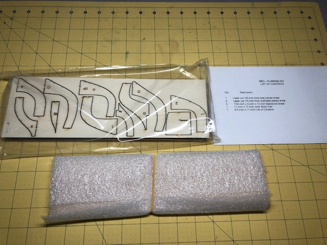
- 44 replies
-
- 7
-
-
- half hull planking project
- half hull
- (and 2 more)
-
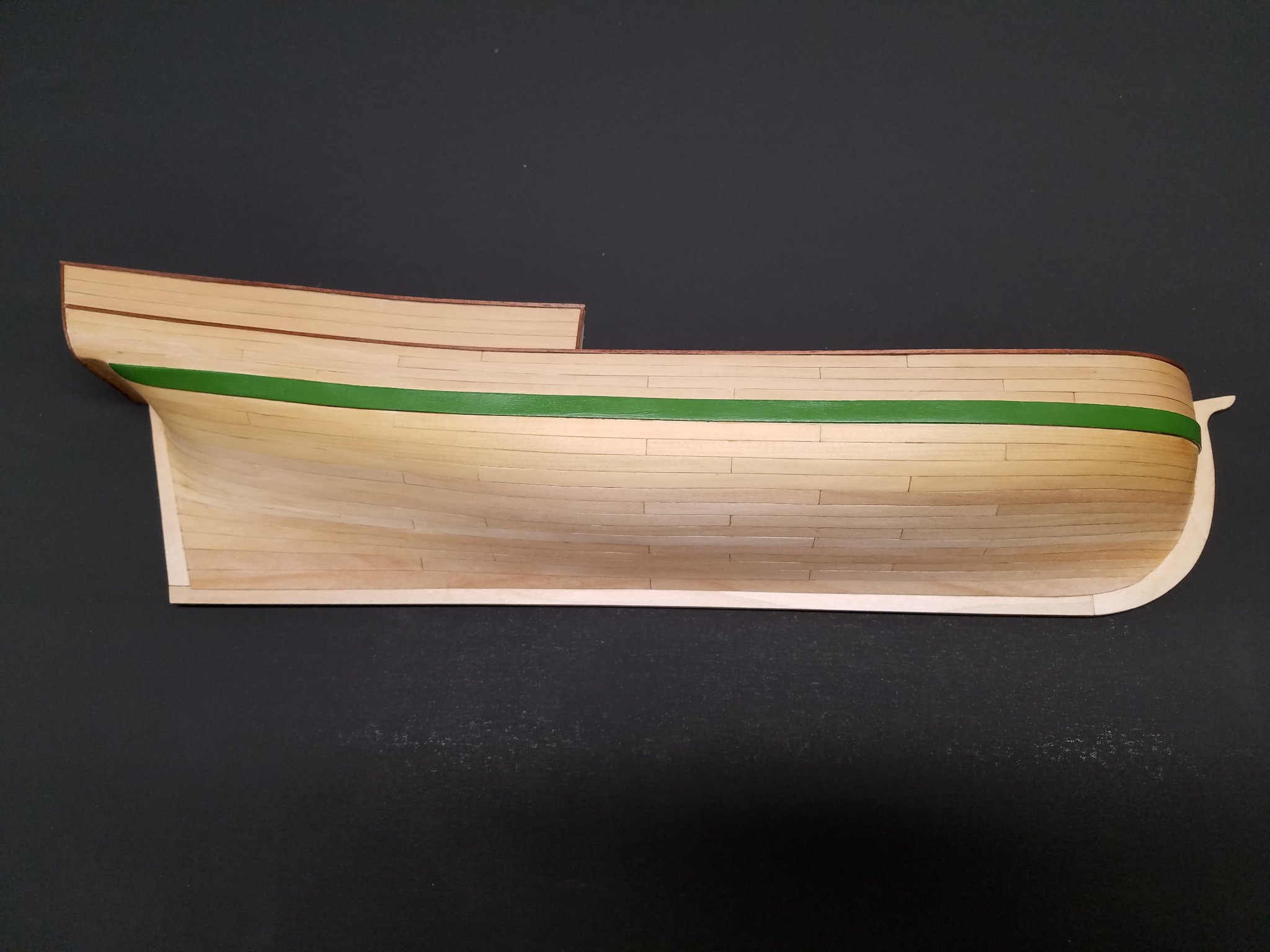
 This will be my take on the NRG's capstan project, sold as a set of plans to help modelers learn and practice scratchbuilding skills: The project can be completed in Advanced or Intermediate mode, depending on the level of tools and skills the builder has. There are three build logs for this that I've found; the original by @tlevine, one underway by @gjdale and one completed by @usedtosail. If I've missed any, please let me know! My build will differ from those above in three ways. First, I'll be following the Intermediate instructions whereas the other two are Advanced, so hopefully this will be helpful for others interested in that track. I have a Byrnes table saw but not the higher-end mills and other power equipment needed for Advanced. Second, the assumed scale for the project is 1:16 and the builds above are all in that scale, though the instructions encourage builders to consider other scales as learning to read plans and convert measurements is part of the project's goal. So I'll be converting mine into 1:24 because I want to display it with two 1:24 Model Shipways naval cannon dioramas I've built previously: Third, I'll be milling my own wood from material I've logged, milled, and cured on my homestead here in rural Missouri. I'll be using maple, cherry, and walnut, producing a similar color profile to my recently completed NRG half-hull planking project: Hopefully these differences will make this build unique and useful to others considering this really cool project. Thanks to the NRG, and especially Toni Levine, for putting this together.
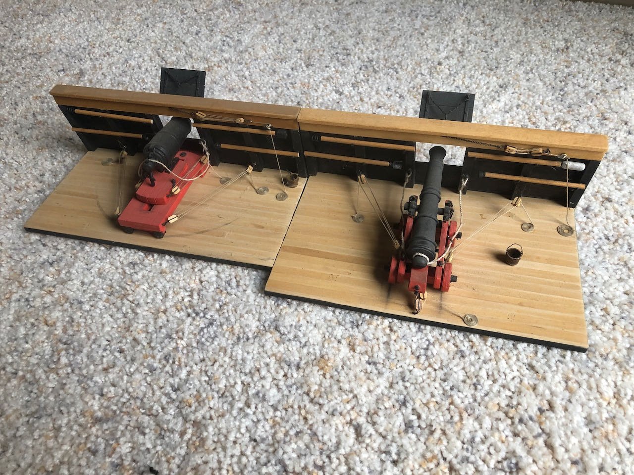
- 69 replies
-
- 10
-
-
 I will be building the half hull planking kit to improve my planking before I start my next model that requires planking. I am currently building a solid hull skipjack in another build log so this log will go slowly as I have free time between building the skipjack. Mounted the plans on a foam board and removed and laid out the keel parts.
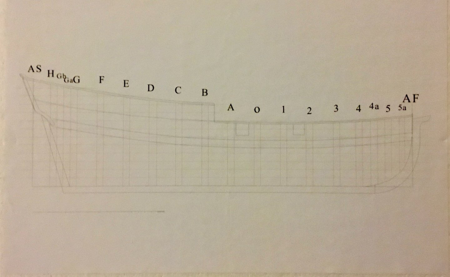
-
This kit was developed by the Nautical Research Guild to teach or improve members' hull-planking skills. As a moderately skilled builder, I decided it would be a good project to force myself to learn best practices and possibly correct poor practices I may have developed. Plus, it seems simpler and more relaxing than my last few builds! Here's the NRG's vision of the final project: There are many build logs for this already, but I intend to add my own twist by doing the planking using wood I've harvested and milled myself from my rural property, where I do a lot of timber management. This is the direction I'd like to take my modeling overall, so this will be a good early test of the goal. I have well-cured cherry, walnut, and maple billets on hand and think a mix of those could look really nice on this hull. Right now my idea is to use cherry below the wale, walnut for the wale, and maple above it. We'll see what happens. Hopefully this is of interest to a few people, but regardless of attendance, I've learned that keeping a build log is a good way to keep myself engaged and organized.
- 36 replies
-
- 11
-
-
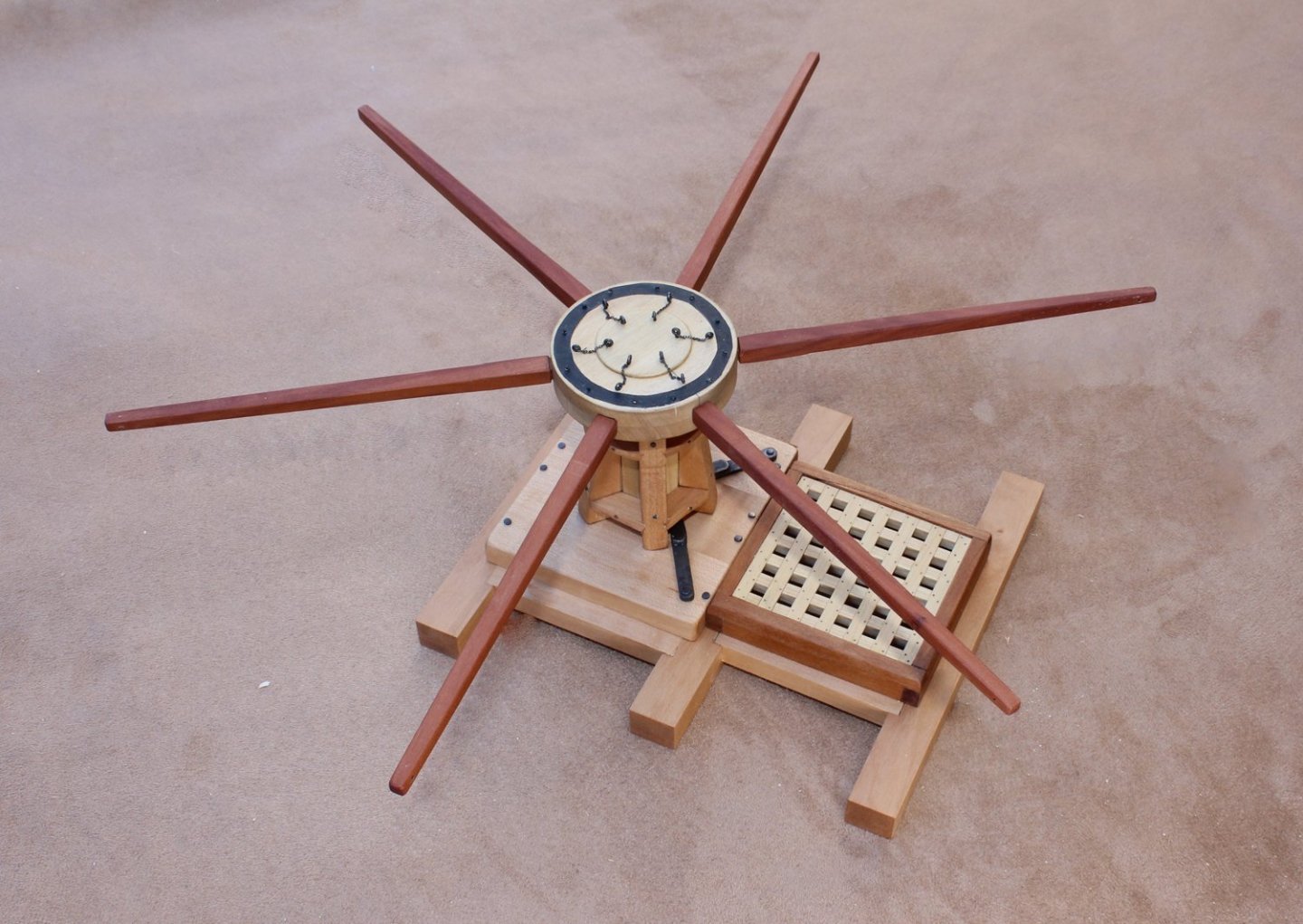
Two years ago, the Guild started selling the half hull kit, a project designed to include modelers who had no access to power tools. The purpose of the kit was to teach modelers how to plank a hull by spiling. The Guild has a new project, actually two projects, designed to expand your modeling skills and develop confidence in the step towards scratch building. As you know, the Guild’s logo is a capstan. Our next project is construction of a capstan, shown on its step, with a hatch and grating. The first project is designed for the builder whose only power tools are a Dremel-type rotary tool and a hobby circular saw. The second is for the builder who has all the “toys”, including a lathe and mill. This is a picture of the completed intermediate-level capstan. Because this is an introduction to scratch building, the project will be sold as a download which will include a monograph and fully dimensioned plans for both the intermediate and advanced projects. No wood is included. The builder will choose the scale of construction and develop their own lumber list. Most of the plans are drawn at a scale of 1:16 (3/4 scale). At this scale, the completed model measures approximately 6” x 6” without the capstan bars and 12” x 12” with them installed. Let’s get started…
- 65 replies
-
- 20
-
-

-
 I ordered this kit as soon as it was released but I wanted to finish my Sharpie before diving in. Of course my father found a small boxcar kit that I was hoping to put together first, but since that kit was incomplete I plan on starting this half-hull in the meantime and learning how to plank (hopefully that will set me up well for my next full ship the Alert). So far all I have done is setup my build board: The instructions suggest using 1/4" foam board, I had a sheet of 1/8" so I cut it in half and glued it together (hopefully all my issues are this easily solved 🙂). I trimmed the board down to the plan sheet and applied tape around the edge to stop bits of foam from following me everywhere and to make certain that the plan was firmly secured to the board (I did first glue it with Elmer's craft bond spray adhesive). Currently I'm sanding the edges of the keel, keelson, stem, deadwood and stern pieces to remove the laser char.
 -
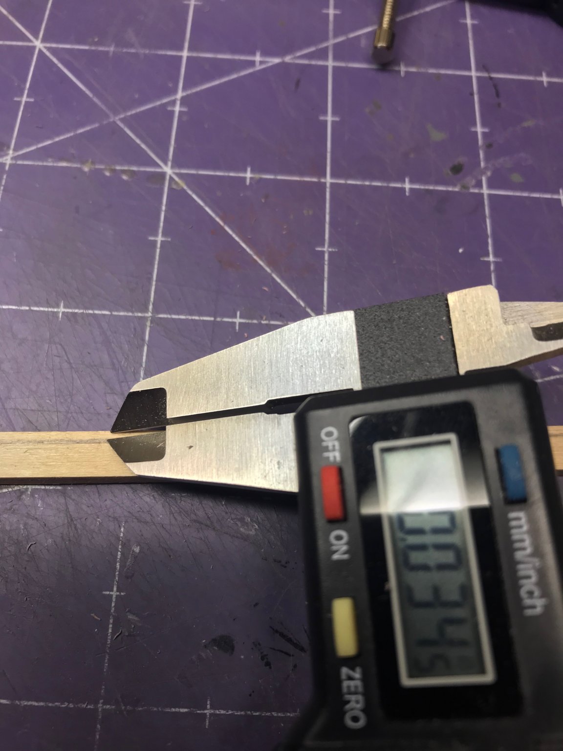
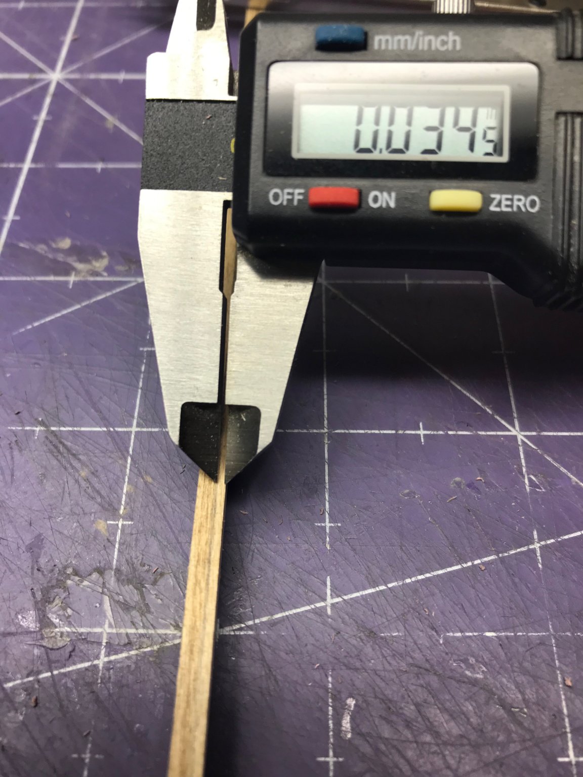
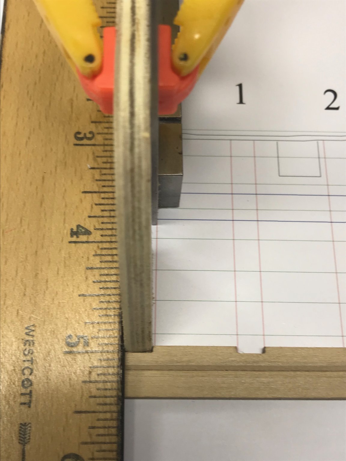
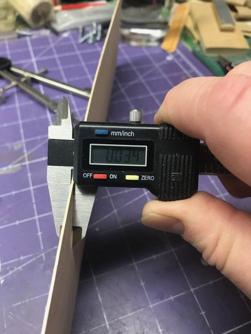
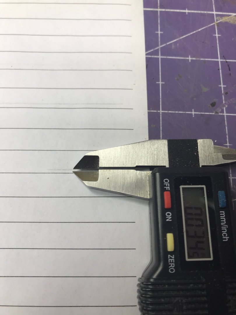
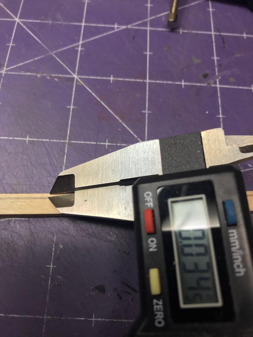
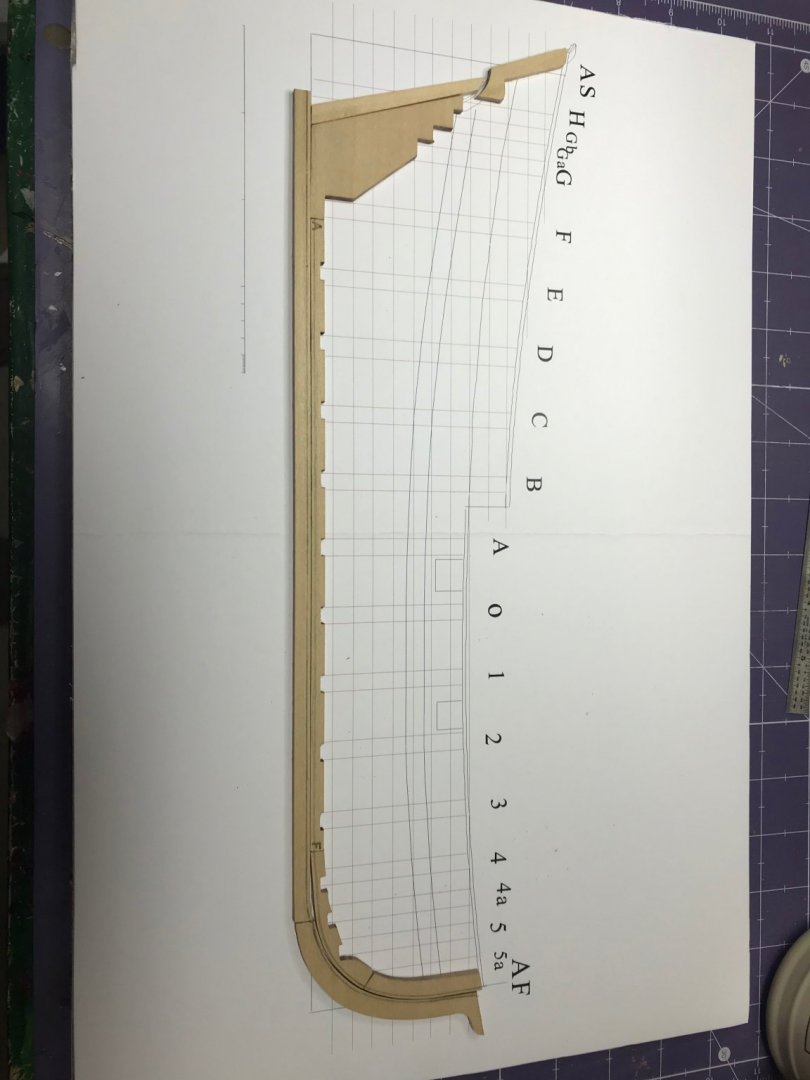
 I am the proud owner of Toni's Introduction to Planking Kit #1 and, since I've got a little time off during the holidays, I decided to get started. I started by reading the instructions. (I've heard that enough times from Kurt to know to start there and it's mentioned in Toni's instructions. It's good advice and I found, even reading through them, I made at least one error early on.) I mounted the plans to a piece of foam board, as instructed. Then I laid out the keel, keelson, stem components, deadwood and sternpost on the sheet to understand how they all fit together. Next step is to cut the rabbet. I'll confess I read this section multiple times and Toni's posts here on MSW, which are slightly different from the instruction manual I have. I'm hoping I got this part right. Toni says, "Measure the thickness of your planking. On this model I used 1/32" basswood which actually measured 0.43" thick." I had to think about that for a minute. 1/32" is 0.03125", quite a ways from 0.43". Then I measured the planking material in the kit: I think this is a combination typo and a little dyslexia. The instruction manual should say 0.034" instead of 0.43". Doesn't matter. I figured it out and understand the point. You need that measurement to transfer it to the keel components, which I did. I did a little experimentation to make sure I drew an accurate line on those components. I set my compass, drew a line on some scrap paper and then measured it with the caliper. I had to do that a few times to adjust the compass properly, but it paid off. I drew lines on both the outboard and top edges. (This is something Toni didn't say to do, but it made sense to me. It the angle is supposed to be 45°, then you need to know both sides of the right triangle to get the hypotenuse right ... right? I have just a couple of observations. First, scraping the char off the components is a necessary task, I know, but I would urge people to take their time with it. I could have used power tools to do this or gone after it with some really coarse sandpaper, but I used the back of an old X-Acto blade as a scraper. It worked great and I didn't risk damaging the components. It took a little longer than other methods, but I think it was a good call. For cutting the rabbet, again, I could have used power tools for that. I decided not to and I'm glad I did. (Toni designed this kit to be done by people without access to all that stuff, so it's not necessary.) I used the X-Acto blade again and then some sanding sticks to finish it off. That worked very well and, although it took a while, the results were better than I think I could have gotten with power tools. Small planes would have worked too. I tried to use mine, but found they were a little too aggressive and thought if I used them I might inadvertently take off more wood than I wanted to. And no project would be complete without some errors. Even though the instructions are very clear about how far aft to go with the keel rabbet -- Figure 10 shows how far to carve it -- I still carved it all the way aft. I corrected that right away by gluing in some scrap wood and returning the keel to a square profile. Best thing about a wooden ship model: there's nothing you can't fix. Here's the final product. Now on to the frames. Per the instructions, "the slots on the keelson were laser cut approximately 1/16" too shallow to help prevent breakage of the basswood keelson while making the rabbet." So I need to deepen them that 1/16" which will bring the distance between the bottom of the frame and the rabbet to about 1/16". Off to the next step! Dan
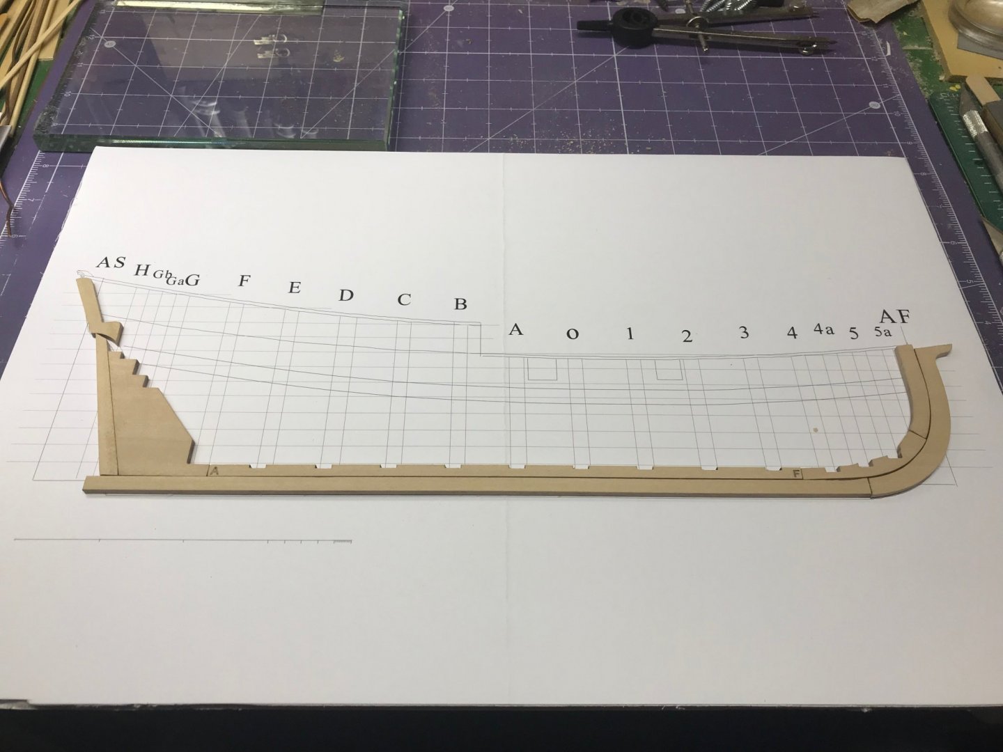


- 39 replies
-
- 10
-
-
 Taking a short break from the Harvey build until the wood I ordered arrives. I had planned to build the half hull before I started the second planking layer on the Harvey - I'd really like to do it right! Kit arrived in perfect shape, and I printed out the instruction manual. I've been reading through Toni's build log and think I'm ready to go. I mounted the plan sheet to the recommended foam board using Elmer's spray adhesive. No wrinkles Started sanding the laser char off of the pieces. It looks like I will need to trim the stemson to get it to align with the bulkhead locations. Has anyone else found that? Will keep on sanding... that's all for now.
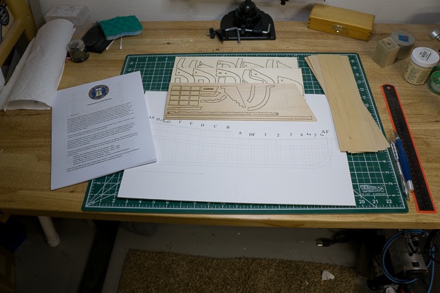
-
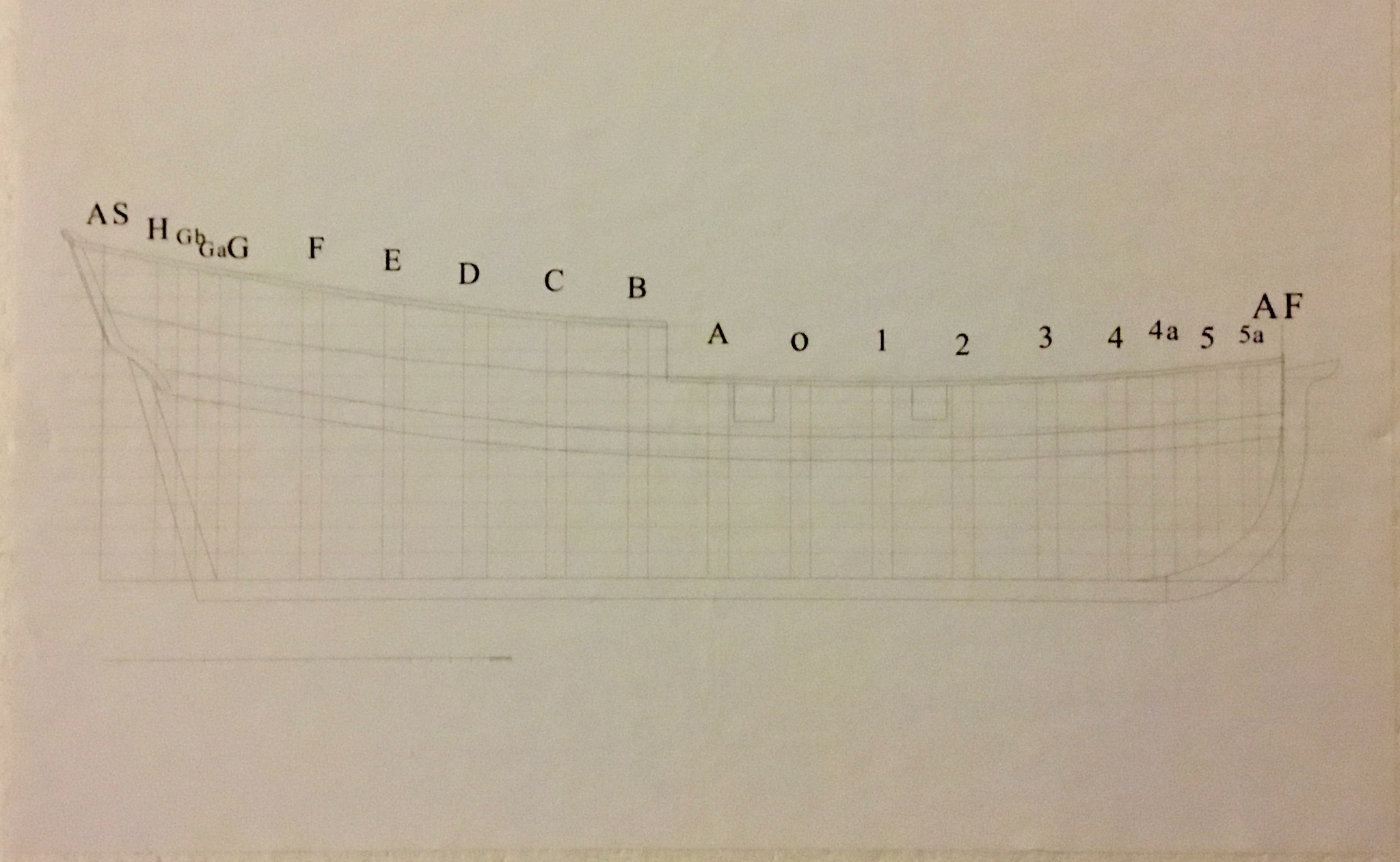
 While building my first boat kit (Chris-Craft) I had a hard time doing the planking, I discovered that a straight plank did some unexpected things at the bow of the boat. I was frustrated and knew I’d have to figure out planking. I came across the Half Hull Planking kit when searching the forum for planking information. I previewed the instructions and realized I didn’t know the terminology. The instructions identify the names of the laser cut parts but there were a number of terms in the documentation that I didn’t know. I found an illustrated glossary of ship terms (it is helpful): https://www.oxfordhandbooks.com/view/10.1093/oxfordhb/9780199336005.001.0001/oxfordhb-9780199336005-e-48 I previewed builds by tlevine, dcicero, modeler masa, and LyleK1 and I’ve been referencing those builds during my build. The kit comes with laser cut pieces to build the frame structure and planking material you cut for each plank. The instructions are a PDF file; the instructions are well written and explain concepts to understand how wooden ships are built. The kit includes an 11x17” print that shows the location of the structural parts along with other significant lines. I mounted the print on a piece of art board but I quickly discovered that I wanted to cut the size down to accommodate the use of clamps during parts of the construction.
-
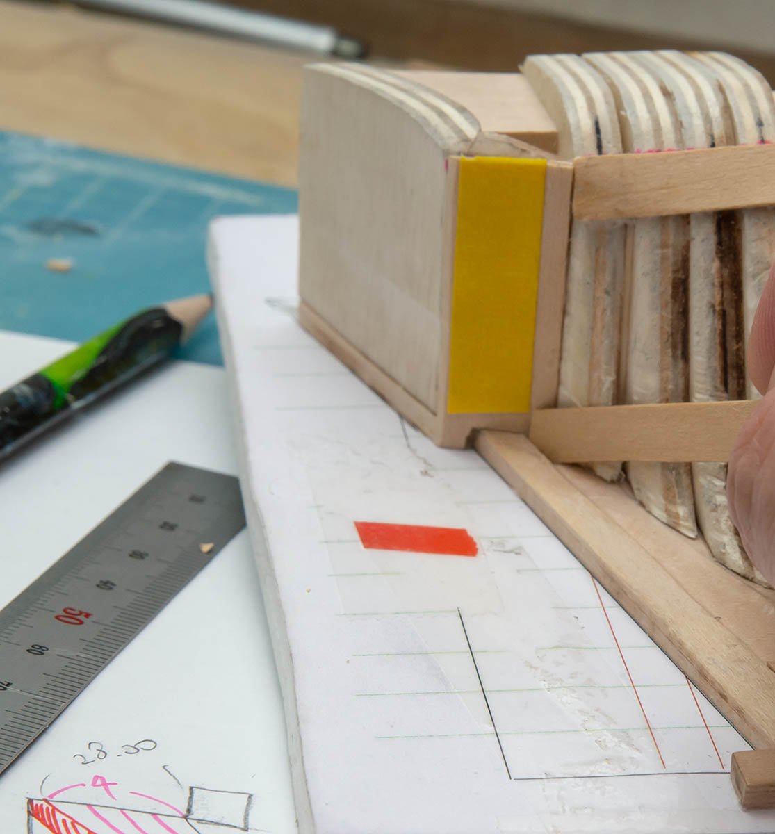
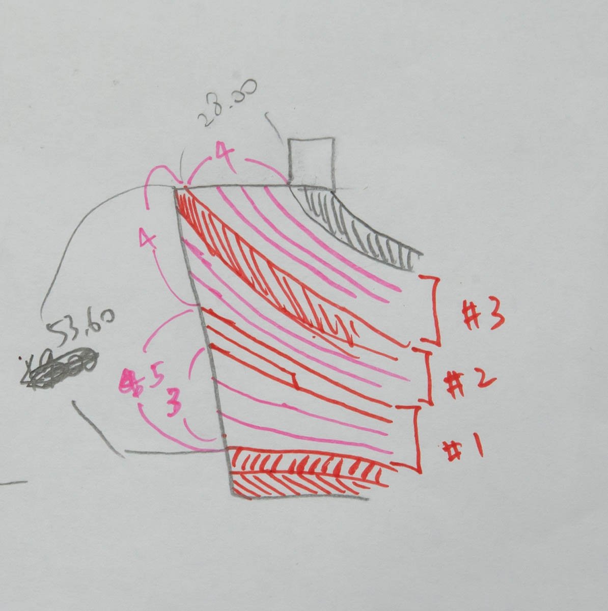
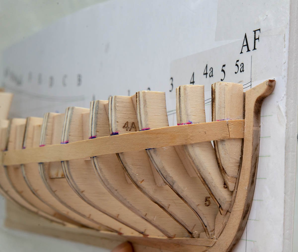
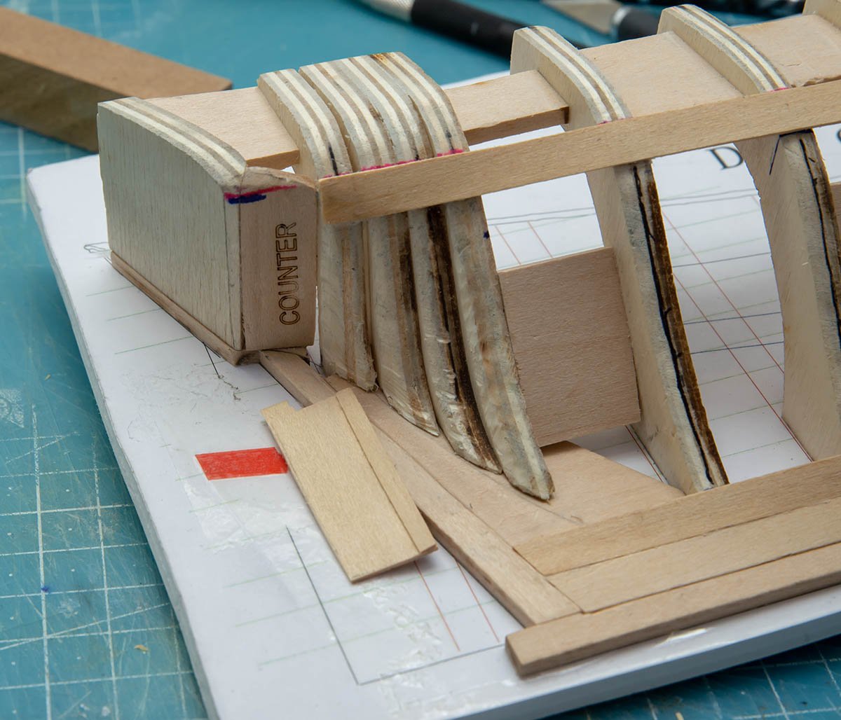
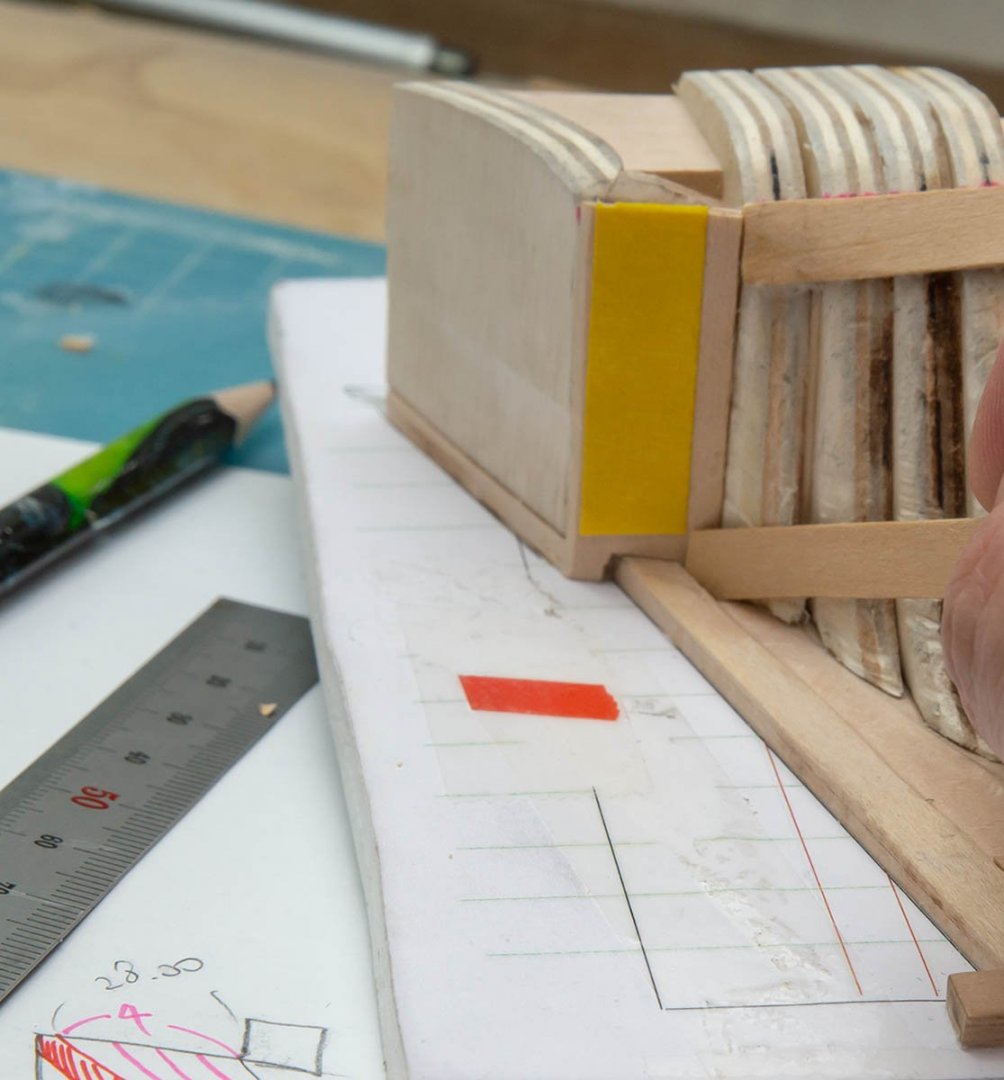
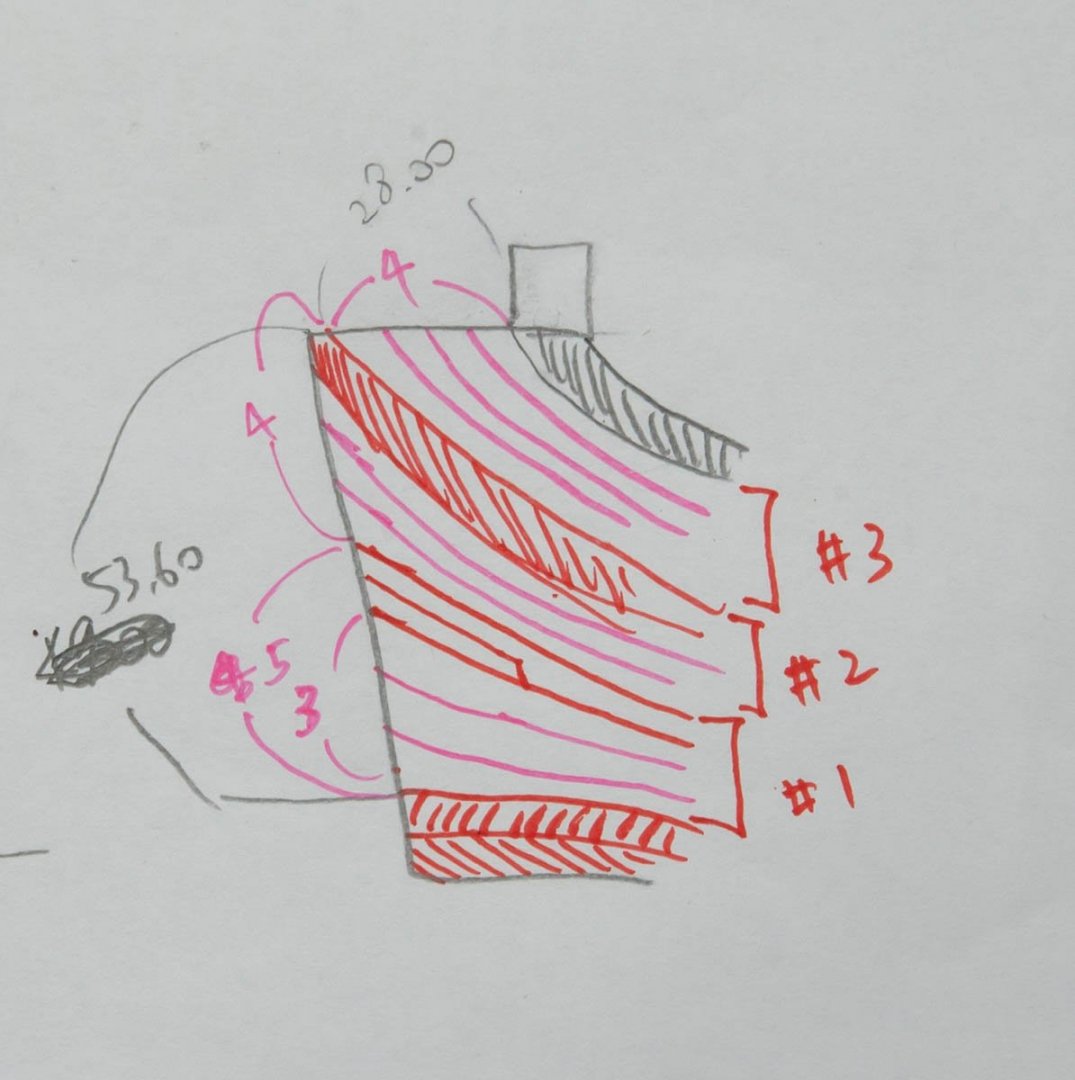
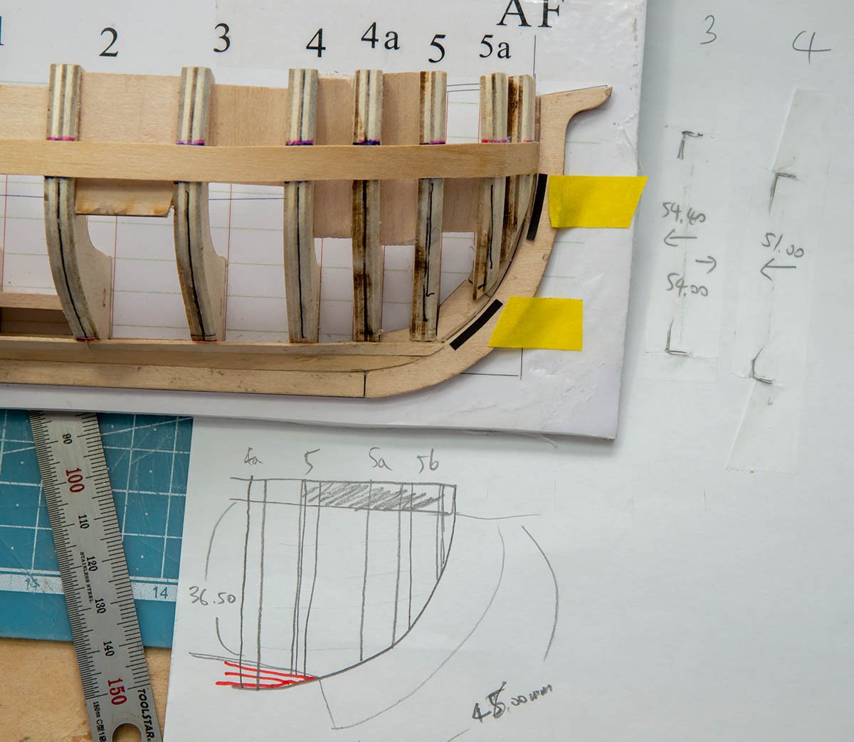
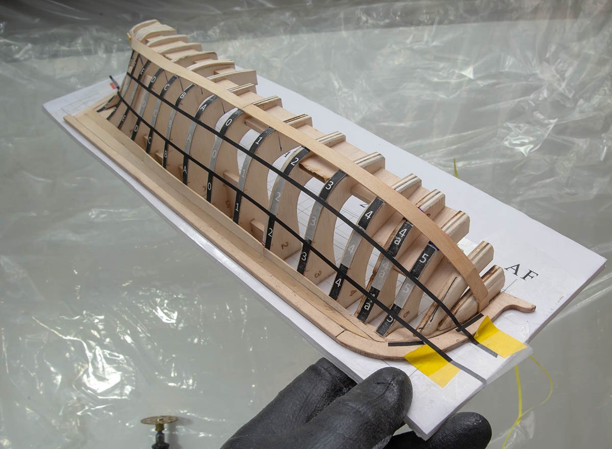
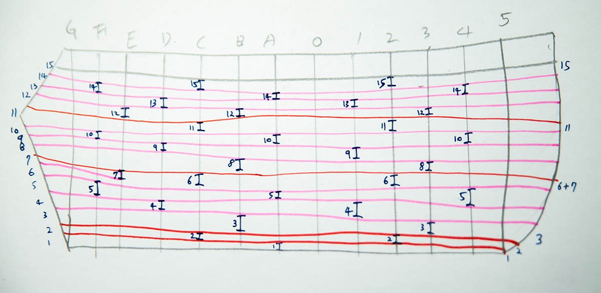
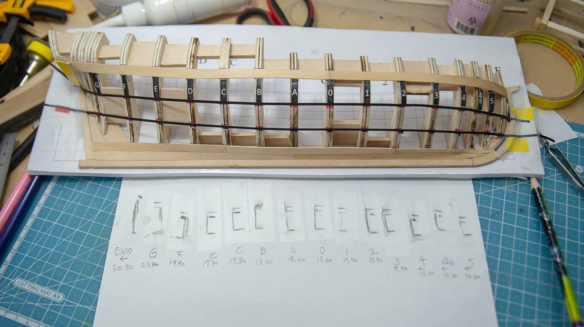
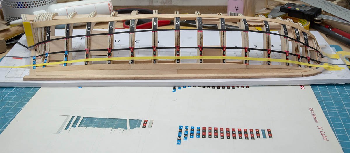
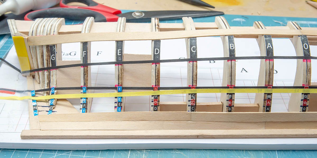
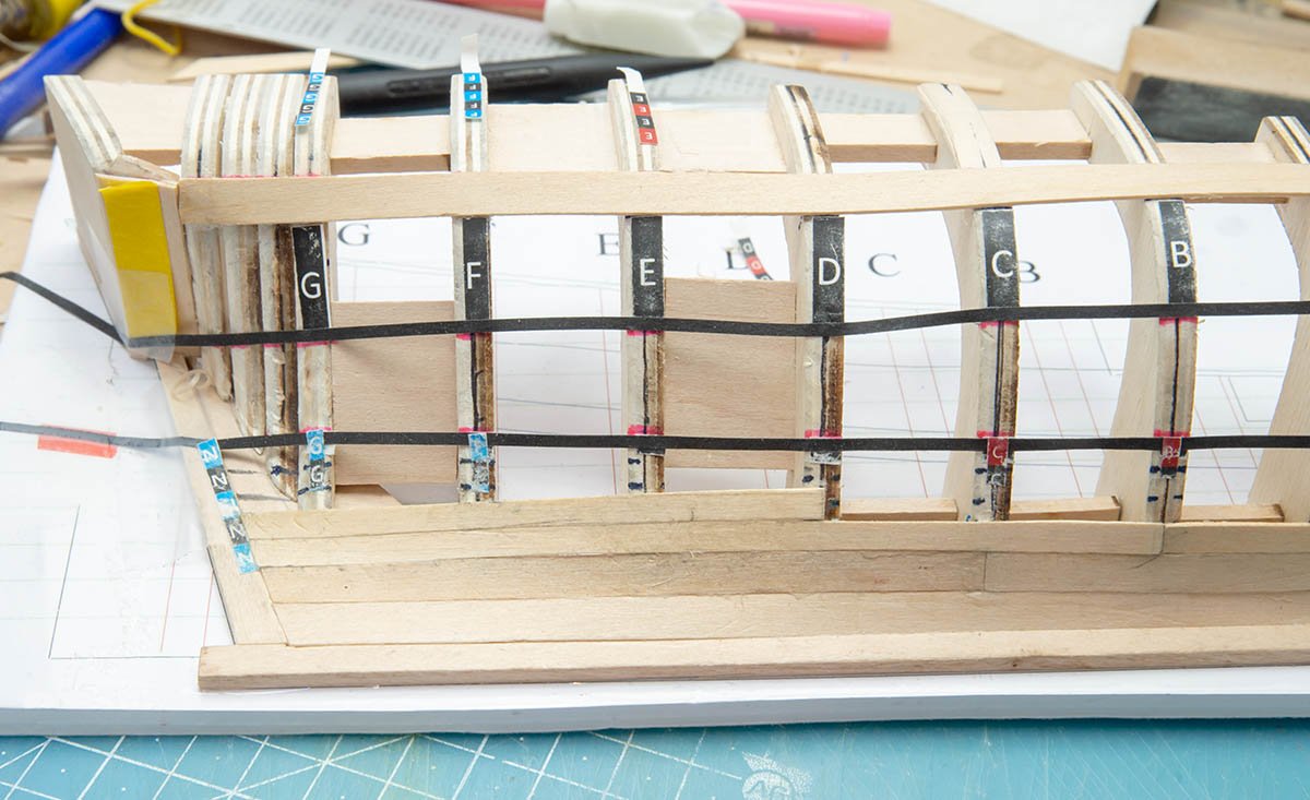
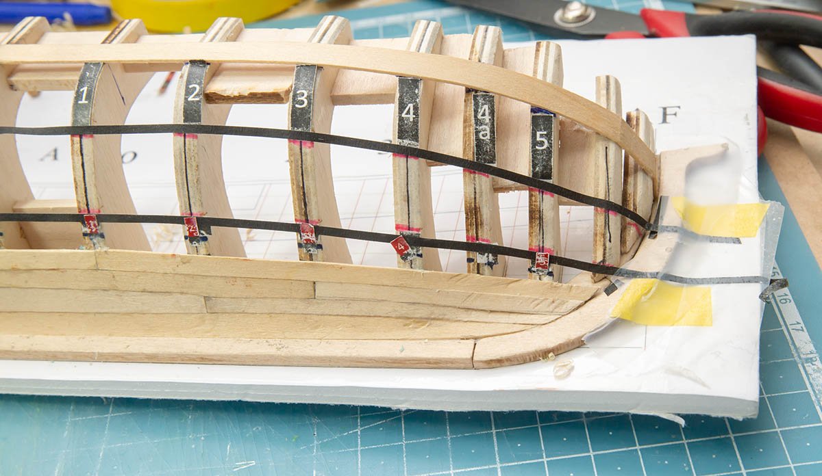
 Hello, This is my last project of this year. I was going to upload this post after completion, but I decided to upload current status. I would like to hear advices regarding planking work. The hull fairing is the most difficult and important job. Hull fairing determines all the planking plan. I didn't understand it on April. It was a reason I stop this kit for half a year. No smile garboard I found that the garboard and the first strake must be under the first waterline before too late. Fixed. For easy work. I jumped to the black wale strake. After that, I splitted lower frames into three segments. This black wale strake also determines all the planking plan and shape of the ship, so I shouldn't have decided to go it first easily. It affects all the lower planks. Broken, but not a big problem. This is a big problem. wrong position. Added thickness to counter. Planks will go to the yellow tape. (Shorter counter area) Carefully peering into Toni's pictures... and understood! Determining how to device the fore end. The yellow tape (by height) is the best for good lining. Peering into Toni's pitures again... and AHA! Measure - printing - adjusting lines - marking - planking, again. Mistake. The pink is corrected line. Getting hard to bend strips... This is a digital temperature controlled iron. Oops. Another mistake. (Very short plank between two frames.) No time to make the strip again... I think I should have to measure all the length of frames when I did hull fairing. I had to draw all the height lines of each planks and black wale strake before I attach it. Also, it would be better if I gave gentle curve to each frames for easier bending. It is very difficult to understand the idea, but I finally learned it from this kit with Toni's guide. (Too difficult to follow it! 😫) If you found any more mistakes or have advices for better result, please feel free to leave a reply. One of my issue is that a minimizing gap between upper and under planks. (Light leaks.) Sanding a little by little is too time consuming. Thanks for introducing this education kit, Toni, and thanks for reading.
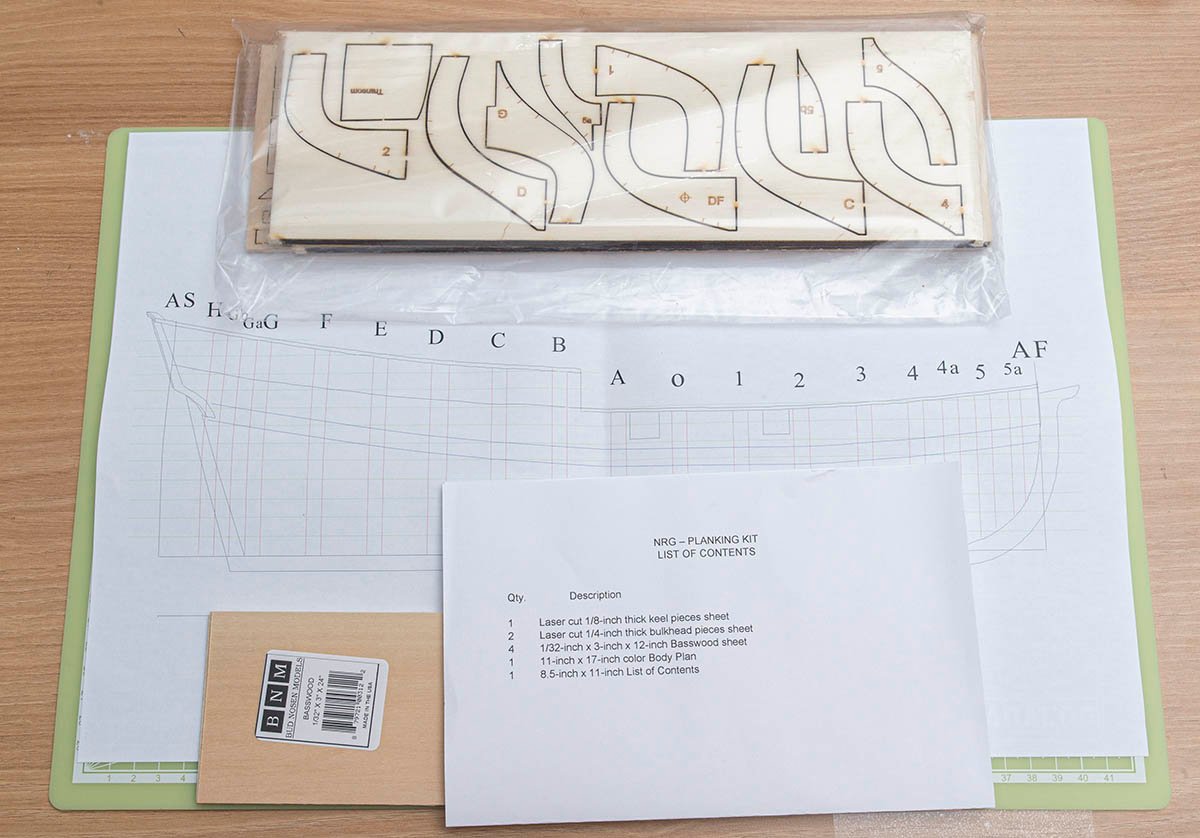


- 13 replies
-
- 9
-
-
- half hull planking project
- NRG
- (and 1 more)
-
 Well, I decided to invest in a side project developed by my ship club mate, Toni Levine (@tlevine). Since my last post on my Syren build log, I've made more progress in some basic techniques of manipulating the planks. Specifically, I received an old plank clamp which was the property of Steve Wheeler (we all miss you, Steve). Hopefully that will take some of the plank trimming frustration away...so far it works great on a few trial planks. In the interim - I've received the NRG tutorial kit. Like others who adopted this side project, I wasn't really sure where to put this build log, so stuck it where others have - hope that's ok. If this turns out, aside from gaining a bit more confidence, I plan to mount it as a wall hanging and make a present out of it...but have to wait and see the final result. Pics to follow... Moving on!
 -
 This will be my first attempt at planking “correctly”. I did complete AL Bounty Jolly which was planked, but in a strange way (I followed the instructions). I have quite a few projects in the shipyard that are POB and POF so I’d rather start with a less expensive kit and fail then ruin the kits I have already purchased in hopes of learning this hobby. I will be taking this build slow as I have other logs going on, as well as a stressful job and a four year old that I chase around on the weekends. My plan will be to finish this half hull with a stained hull...I’m also contemplating coppering the hull as a learning experience as well.
 -
 I'm joining the fun of this "learning exercise". Started: Using a foam core building board. Rabbet cut. (Without much thought I started cutting the rabbet on both sides of the keelson before I remembered that this was a half hull - oops)