
James H
-
Posts
5,538 -
Joined
-
Last visited
Content Type
Profiles
Forums
Gallery
Events
Everything posted by James H
-
 Do you know anyone just inside the US border who would receive for you, and you could pic up from them? Is that possible between the US and Canada? I know that feeling! 😆
- 502 replies
-
- 1
-

-
- Quadrireme
- radio
- (and 1 more)
-
Is this for the first layer of planks? Would a nailer with a rounded head be a better option maybe? I'm just thinking it would sit comfortably in the palm of your hand. This is a ModelCraft nailer.

-
Here you go. There are some other shots in this log showing my hand too.
- 473 replies
-
- 24
-

-
-

-
- Indefatigable
- Vanguard Models
- (and 1 more)
-
Those are now unfortunately out of production. If you do want some excellent razor saws, try ASK, but they aren't like the one I've shown. We have reviews of those tools here. Tell them I sent you
- 473 replies
-
- 5
-
-
-
- Indefatigable
- Vanguard Models
- (and 1 more)
-
...and the top of the upper strip (directly below pear) sits along the top edge of gun port. Scrap material fills the gaps between. Works a treat.
- 473 replies
-
- 13
-
-
- Indefatigable
- Vanguard Models
- (and 1 more)
-
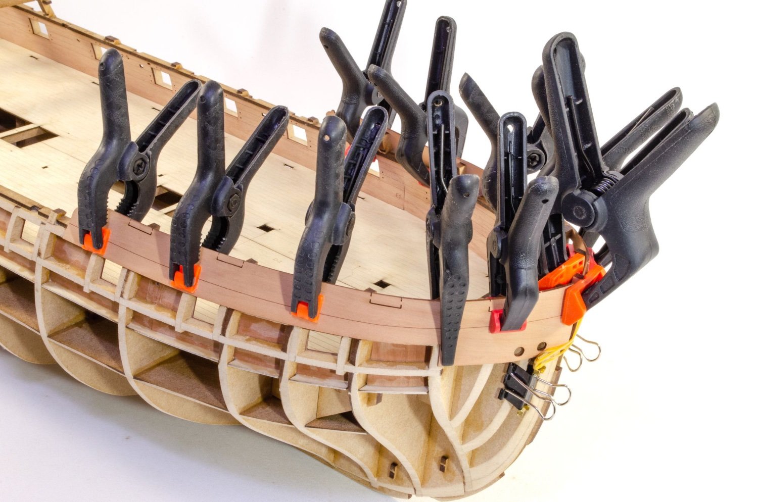
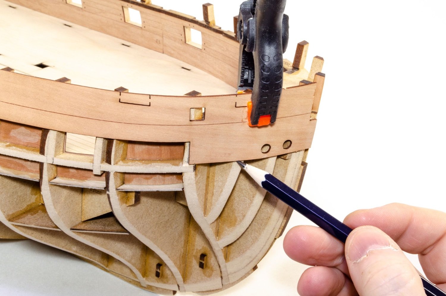
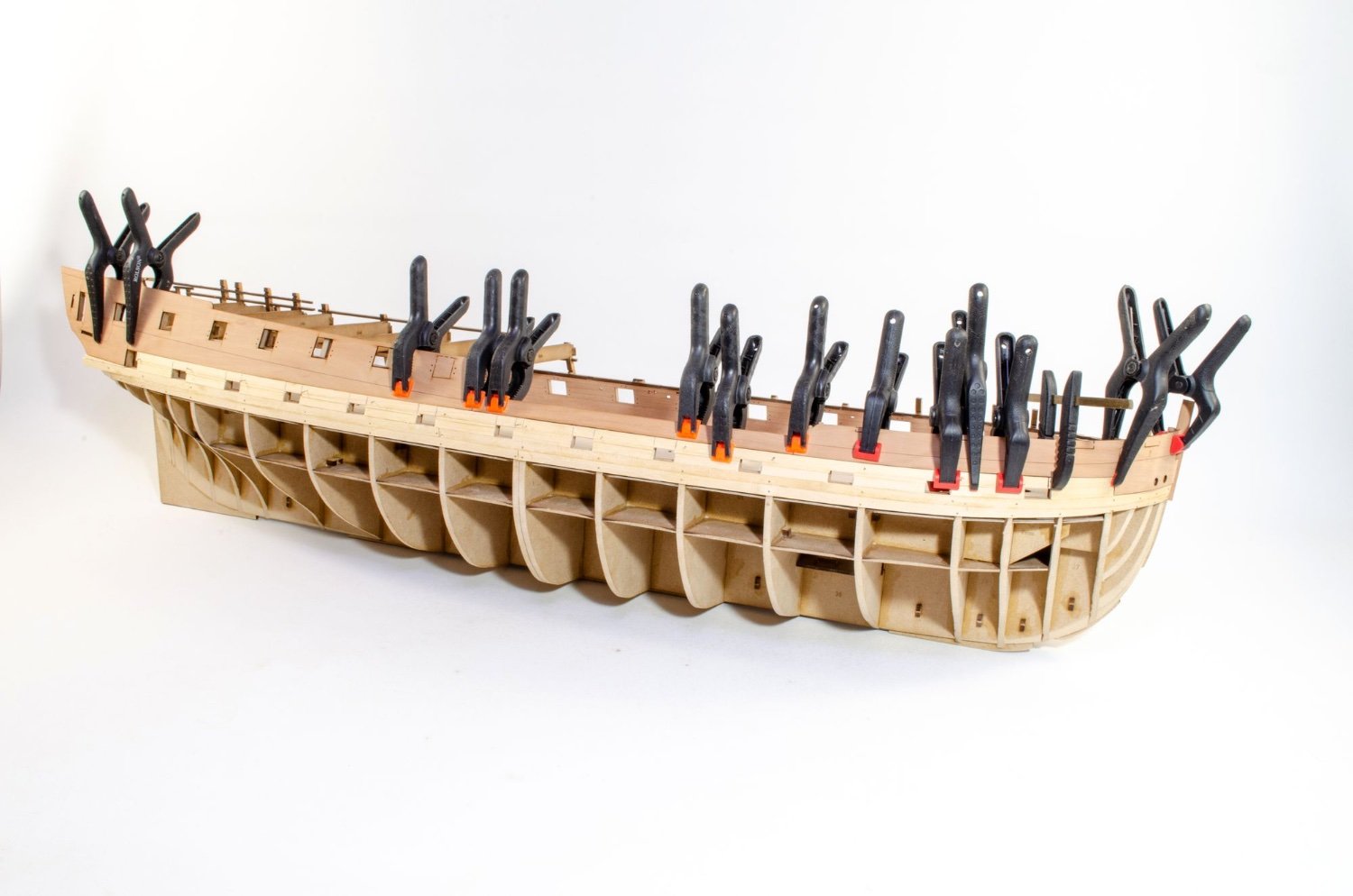
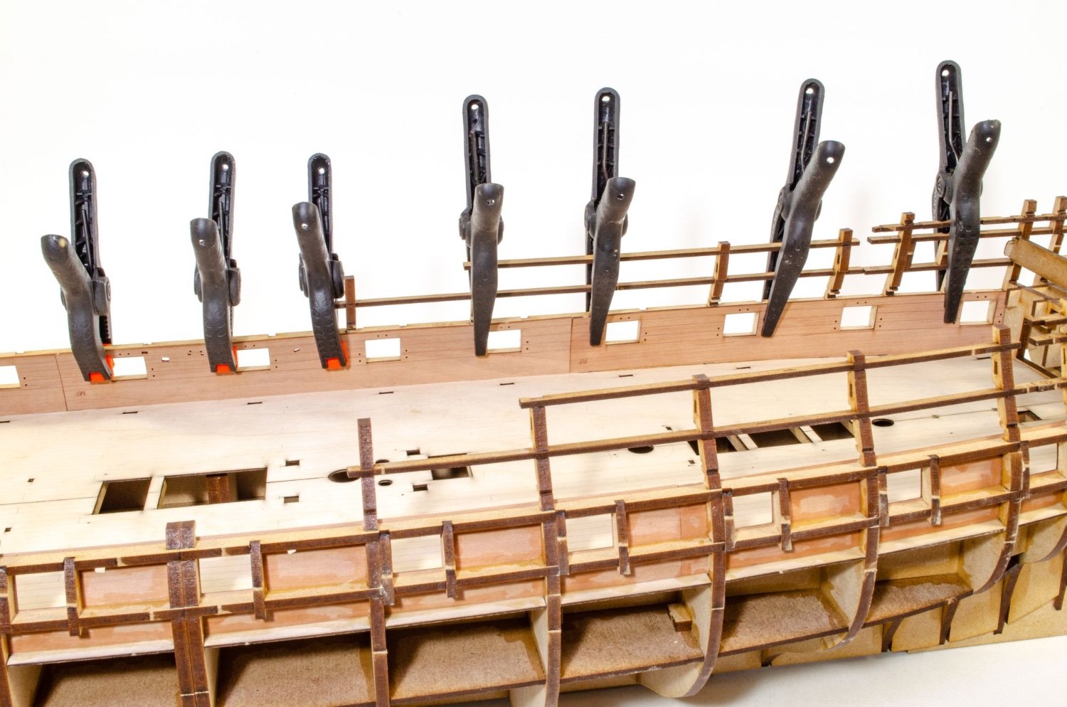
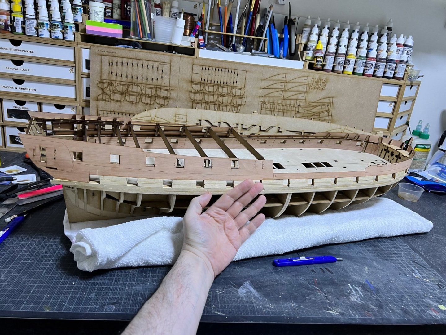
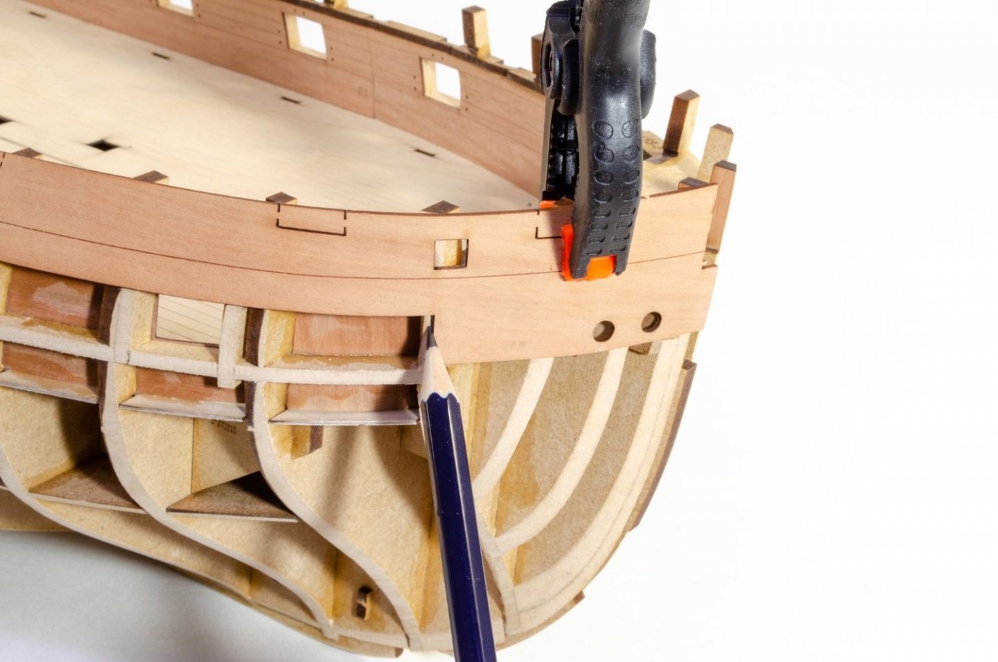
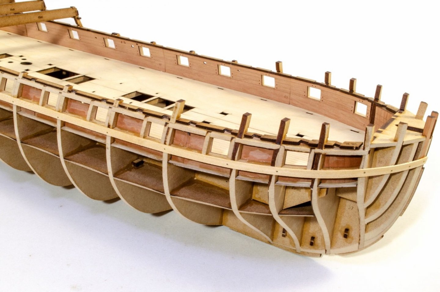
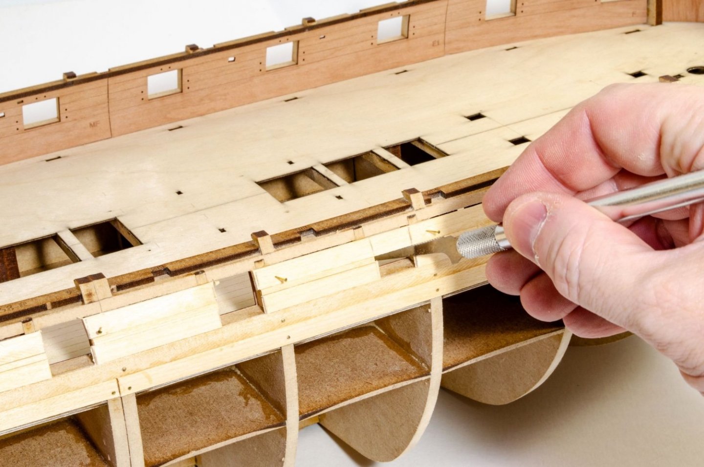
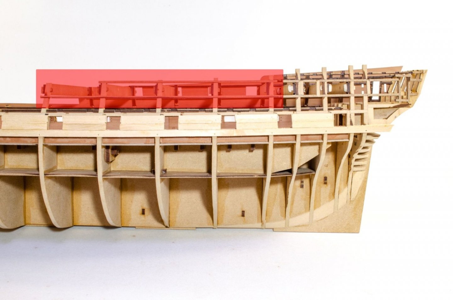
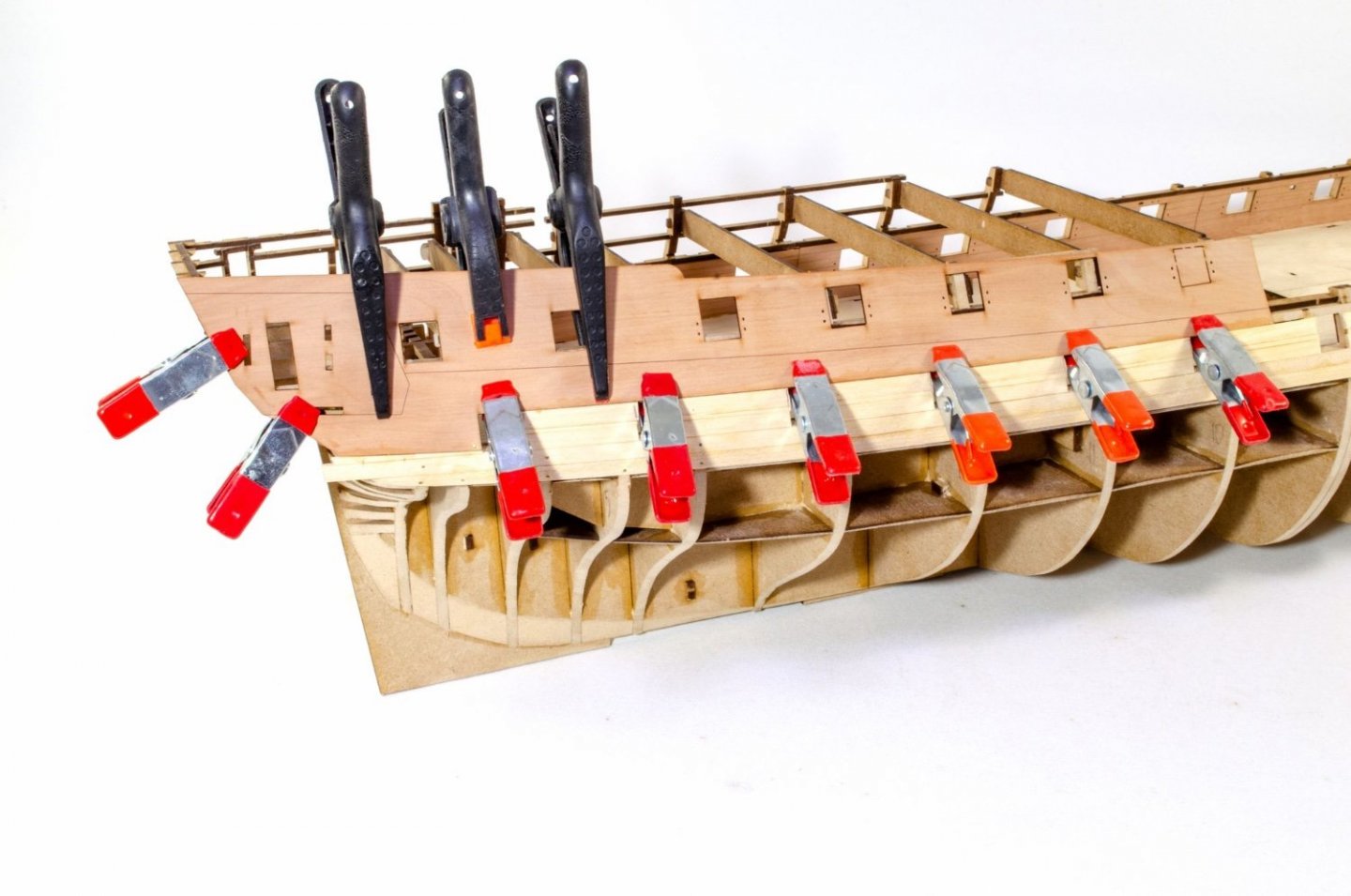
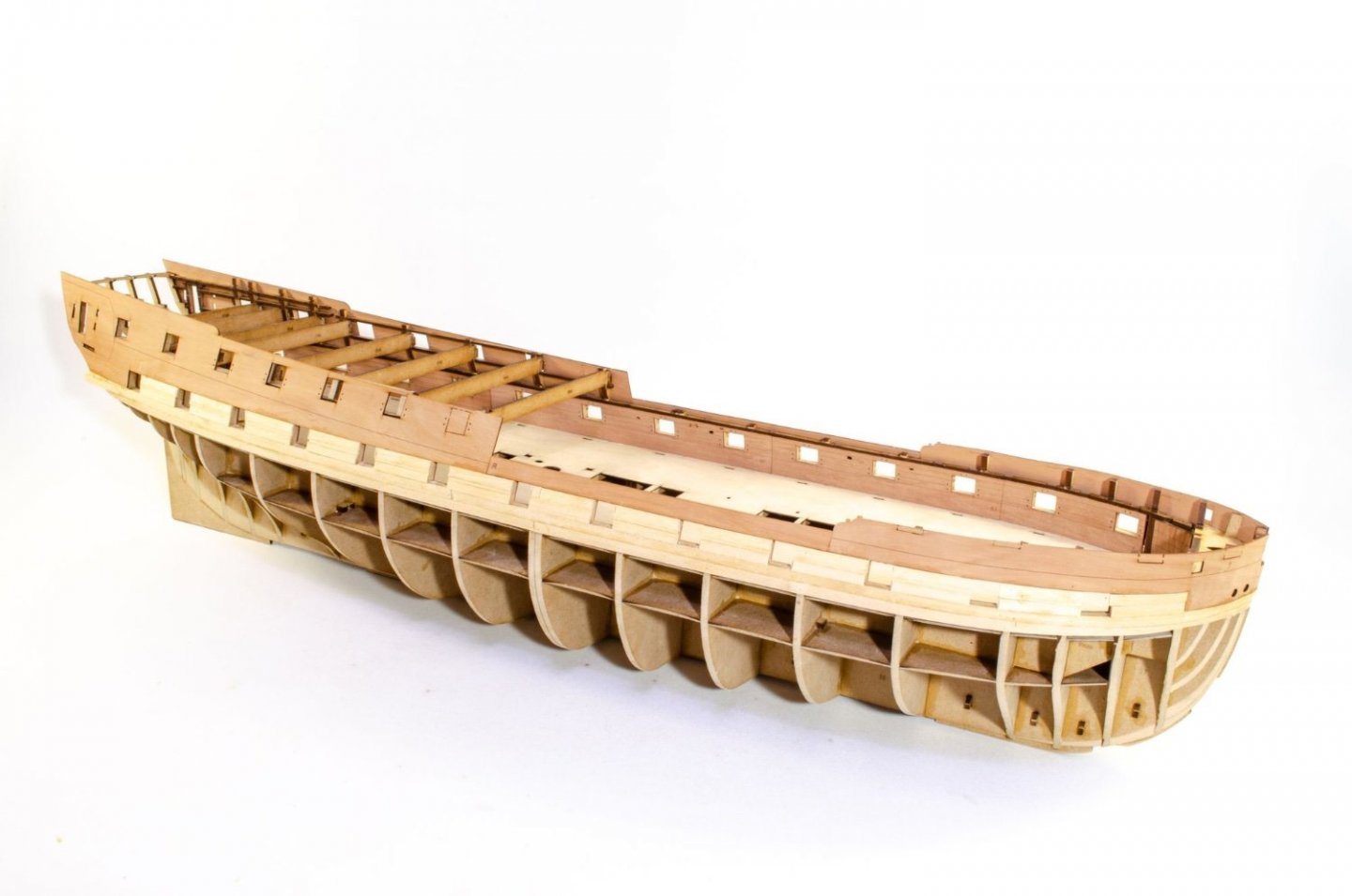
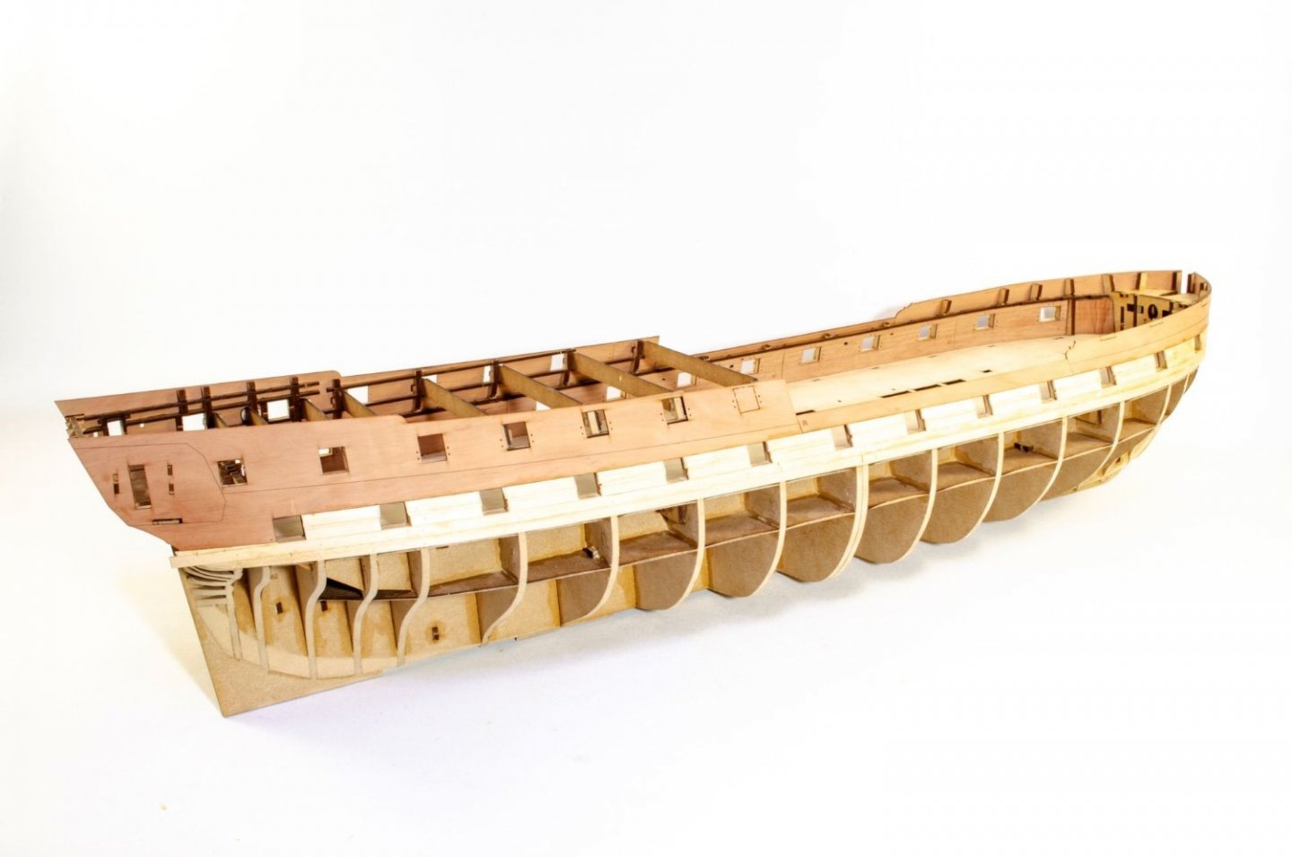
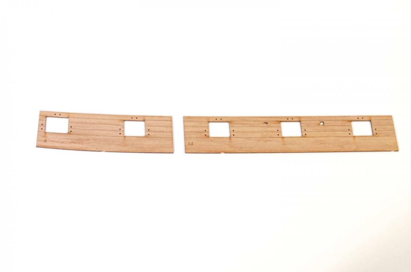
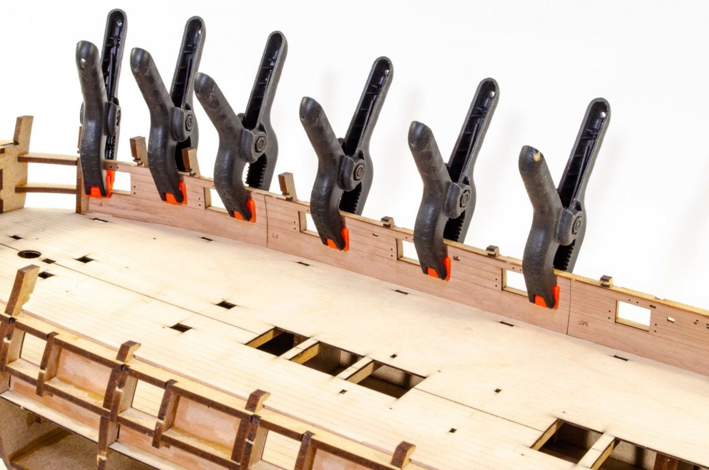
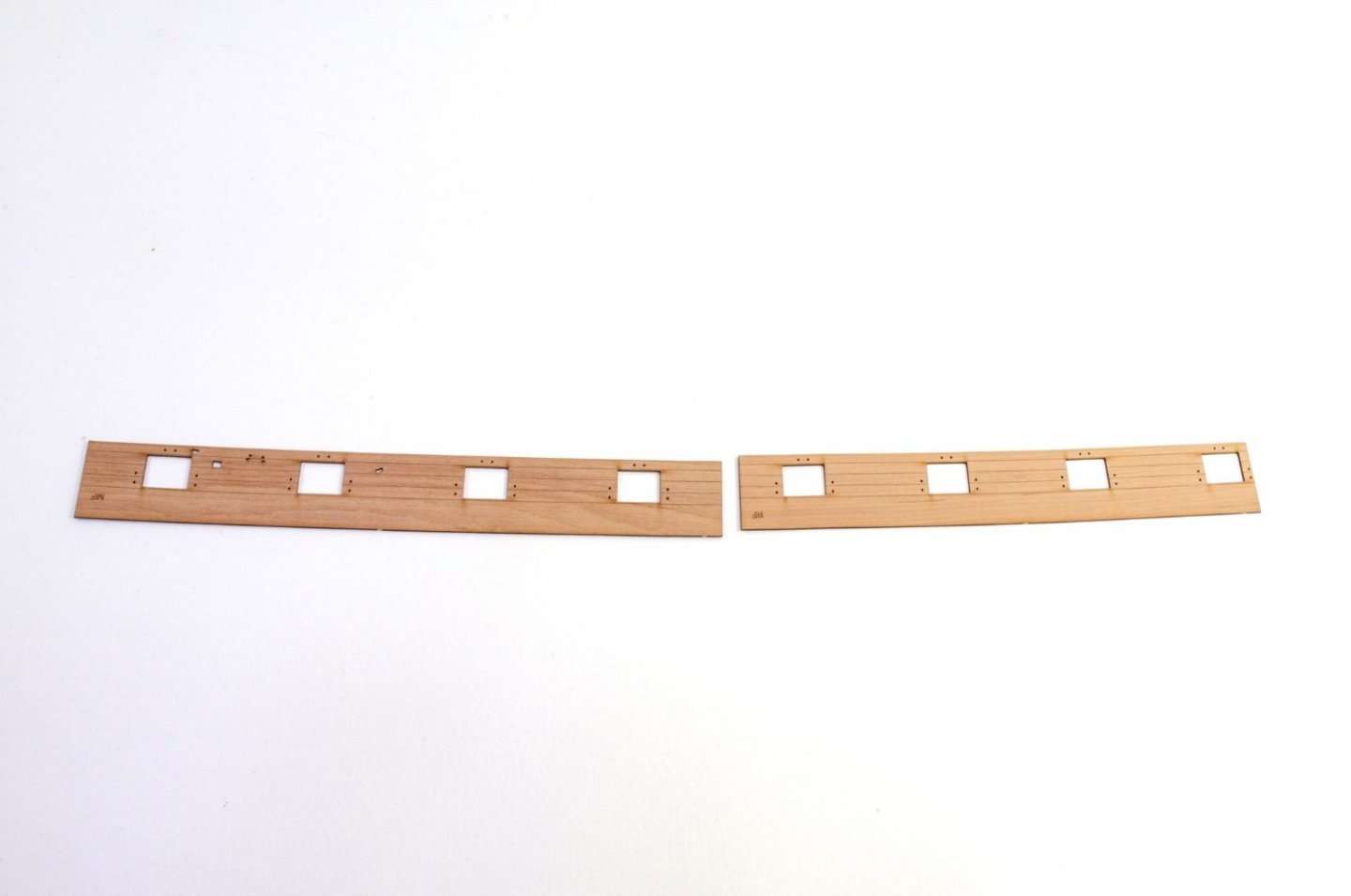
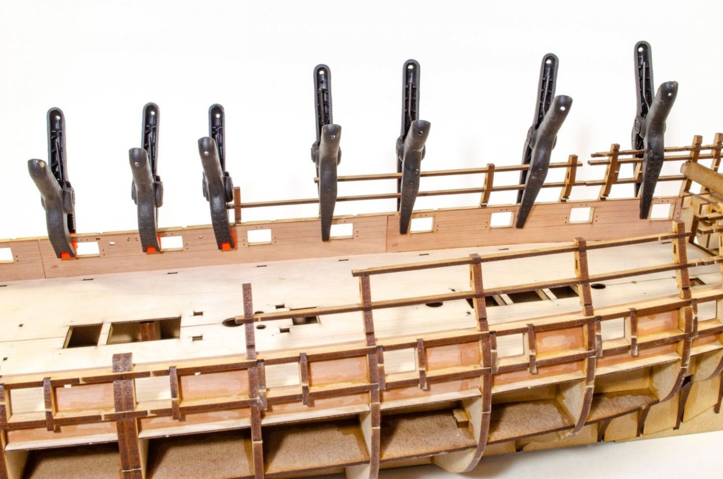
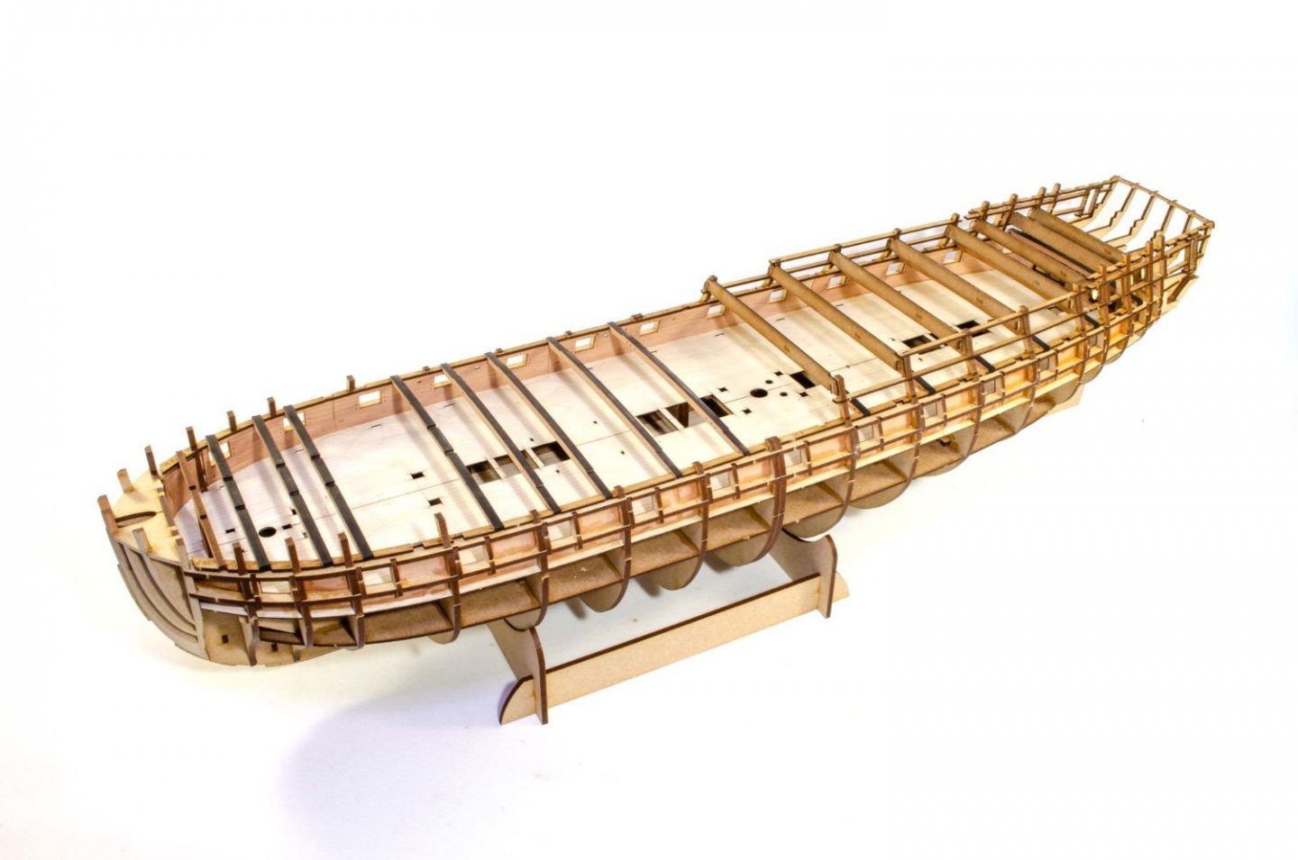
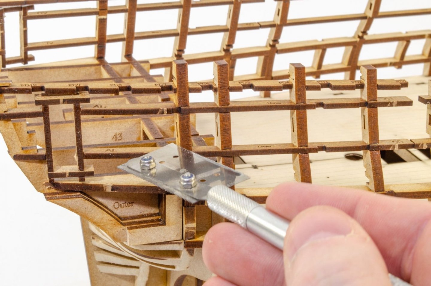
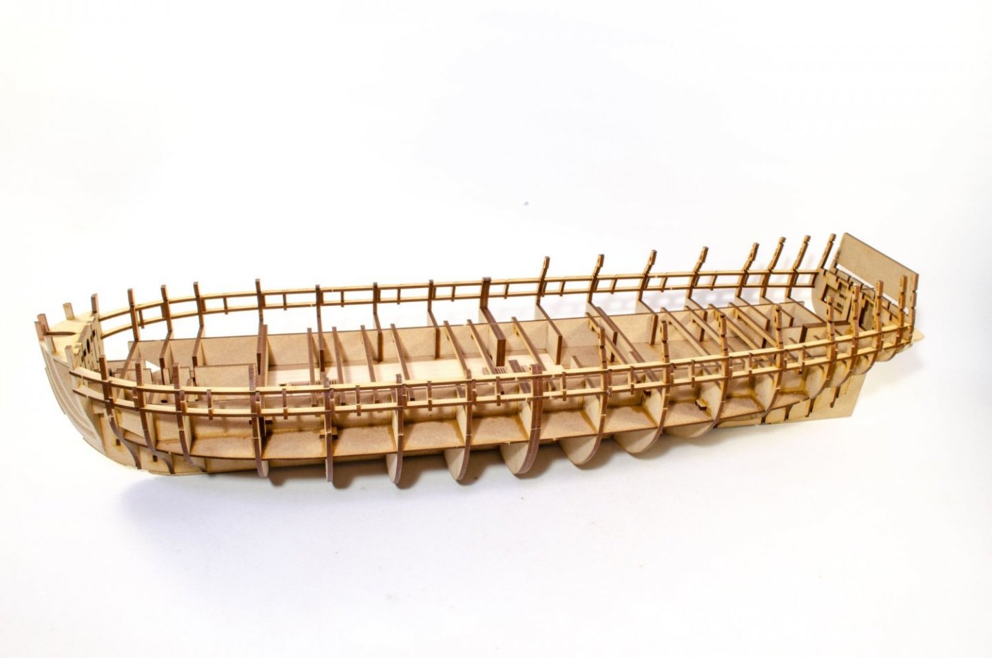
Just for some info, Indy will be approx 880mm tall. Ok, onto business. The hull is now faired. This isn't really a task you can sit there with a piece of sandpaper and hope to achieve inner calm. Chris finally talked me into getting a palm sander (mouse), so I splashed out on a Black & Decker one. Even with this, fitted with an 80 grit pad, this job still took me a total of about 5 hours, along with the final task of wrapping some sandpaper around a 12 inch piece of thin ply to absolutely ensure the curves were right....plus the joyous task of blending those last bulkheads and fairing blocks into the keel. There is a lot of regular planking on Indy, but the inner core of the outer bulwarks are laser cut. So as not to stress out the forward bulwarks and those temporary gun port sections, these were first soaked and clamped in place. These were left for a full 24hrs to dry out and shrink back to their normal size. Pear has a hell of an expansion, even when soaked for 30 mins in hot water, so you really need to find a book to read, guitar to play, or TV to watch while this dries. Now that the parts are completely dry, I draw around the forward position of the bulwark so that I have my positions for the flow of the first plank that runs below the gun ports, and also the extent of the planks above this. It's important to know here that this pear part sits along the top of the gun ports on the main deck. The pear bulwark is now removed and the first 1.5mm thick lime strip laid along the bottom edge of the gun port sills, and along the lower line I've just drawn. On the prototype, each plank is 500mm long, and they meet up on the double thickness bulkhead #9. We're not yet sure if that will be the case on the final product. The back end of the same plank run is now installed. These planks are pinned until dry. If you pin all the way through, they will penetrate through the inner bulwarks, but that doesn't matter as any holes will be in the area covered by the spirketting. The pear bulwark sections are now temporarily clamped into position so the bottom edge runs along the top edge of the gun ports. You don't need top do this but I just considered that it was good insurance that the plank that runs directly underneath these pear parts, would be properly installed and a snug for in that area.It also gives you something to finally sit these parts onto later so you have a much better chance of both sides being exactly equal. Care is taken not to get any glue on those pear bulwarks. The spaces between the gun ports are now filled up with lime strip. This doesn't need to be neat at this stage. They'll be cleaned up later. A razor saw is now used to cut away the lime strip in the top row, that is partially obscuring the gun ports. The pear bulwarks can now be reinstated, but before this happens, you need to know a little bit about the side framing of the rear half of Indy. Not all of it will become a part of your finished project. When it comes to gluing the rear sections on first, the area in red here WILL NOT have any glue applied to it as that section will later be cut away. You can see the area with glue covers the the lower area just underneath the red area and for the rear section, it terminates at the point where the longitudinal strips were installed in sections. When you look at the model and my previous photos (without red marks), you can see that split in the strips, denoting the two areas. The rear bulwarks are now finally glued into position after some final measuring, ensuring both sides are in exactly the same position. This isn't too difficult now that this part sits upon that lime plank. Other factors also help too, such as the two rear gunport frames on the quarterdeck and the quarter gallery doorway. Just check at the back end to make sure things align with the stern timbers. Of course, you don't need to worry about gun port alignment on the rest of the quarterdeck gun ports as those frames will later be removed, as discussed. 2 inch clamps are very useful here to make sure the bulwark is squeezed into the hull curvature, as they can hook through the gun ports. The mid and fore pear bulkheads are now glued into place. And for the last part of this update, here's how she currently looks. Next job is to cover that lower real estate in lime planks. Remember, this is the same size as Agamemnon! Until next time....


- 473 replies
-
- 56
-
-
-

-
- Indefatigable
- Vanguard Models
- (and 1 more)
-
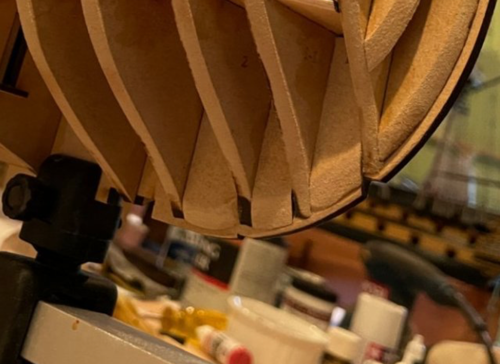
The first time I broke out the MDF frames, I was more than a little wary. Actually, just go gently and it'll be fine. My suggestion is to snip away the bridge between the two halves and twist each side out separately.
-
Simply gorgeous and the colour of the finished timber is perfect. What do you use to varnish/oil your project?
- 216 replies
-
- 7
-
-
- masterkorabel
- ships
- (and 3 more)
-
Welcome to MSW Great to have you with us. Let us know what your choices of project might be.
-
I order mine from Amazon.
-
Is Plastikote Red not available in the US? I used that as Chris recommended it, and it seems quite universal when it comes to getting hold of it.
-
That is gorgeous! Oh, try 2mm planks.
-
It's a tough job, but someone has to do it 🤣
- 473 replies
-
- 13
-
-
-
- Indefatigable
- Vanguard Models
- (and 1 more)
-
I build my stuff in a tiny box room which can barely fit a single bed and a wardrobe. Unless you're working smaller than that, you'll probably be fine. Even a kitchen table would be easy enough.
- 473 replies
-
- 12
-
-
- Indefatigable
- Vanguard Models
- (and 1 more)
-
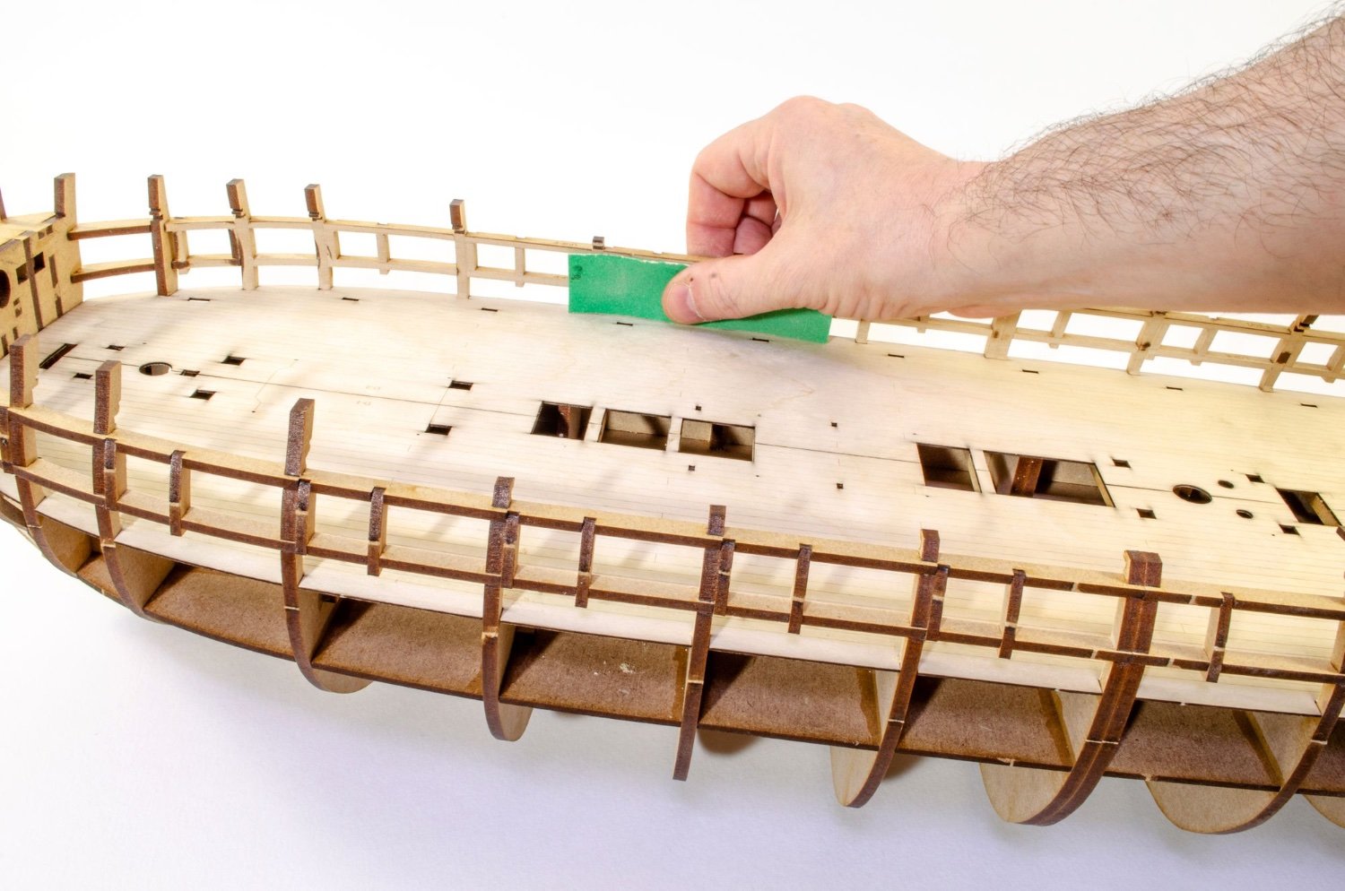
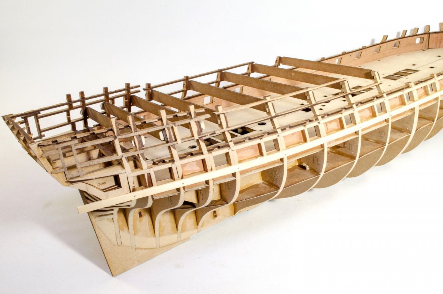
Another update. Not too much to show this time, but there was a lot of work in terms of sanding and waiting for soaked parts to dry before gluing etc. Before I could proceed, I needed to sand the inner bulwarks. This isn't too bad of a job...just time consuming. Despite my pic, you're best rolling the hull onto its side on a towel, and applying pressure downwards when sanding. This is done until everything is nice and even. Each 1mm interior bulwark is split into four easy to manage sections. To lessen any load on the frames, so as not to cause any spread in them, all inner bulwark parts were soaked for 30 mins before clamping into place until dry. These were left 24hrs so they were entirely back to their normal size. Pear swells a lot in water, so it's vital you know, beyond doubt, that there's no swelling left. Once dry, all parts were carefully aligned to the port frames, glued into place, and clamped until set. Provision now needs to be made for the eventual deck beam positioning. This is done using some 2mm MDF frames which slot into the bulkhead beams, above the inner bulwarks. There are two per side. These fit with a nice, reassuring push, but at this stage I don't glue them. A good number of the 6mm pear deck beams and 5mm boat beams are now sotted/hooked over the MDF parts I just installed. This is done to check that the position of those MDF parts are absolutely in the right place. These beams are NOT glued in yet, obviously. At this point I've also reinstated the MDF temporary beams across the quarterdeck bulkheads. Again that's just to make sure every dimension is exactly as designed. Once happy with everything, the MDF deck beam mounts are brush glued into place. Lastly, the pear beams are removed and carefully put away somewhere safe. The temporary MDF beams remain in place to help me with the hull fairing, and that's the next job. That's all for now.


- 473 replies
-
- 43
-
-
-
- Indefatigable
- Vanguard Models
- (and 1 more)
-
What does...
James H replied to Gregory's topic in How to use the MSW forum - **NO MODELING CONTENT**
That's because that's not new content. If there is any topic within those forum areas which is new, the main forum area will show the 'NEW' text. Not everything has to be new. -
What does...
James H replied to Gregory's topic in How to use the MSW forum - **NO MODELING CONTENT**
It means there's new content in those areas since your last visit. -
I'd fair those filler blocks in a little more between the bulkheads. They shouldn't be standing proud of the bulkheads as they do.
- 73 replies
-
- 5
-
-
- Sphinx
- Vanguard Models
- (and 1 more)
-
You're doing a great job of Sphinx. You'll notice some design similarities to Indefatigable.
- 73 replies
-
- 2
-
-
- Sphinx
- Vanguard Models
- (and 1 more)
-
Sort of. The bench pics Chris sends me are usually of 2 or 3 test fits, sometimes with different sequences. I spend a lot of time going through many hundreds of photos and working out what I think is the best order of doing things, especially as the parts I've been sent often differ to the ones in the photos. Those differences are little things like the inner bulwarks changing from 3 parts per side to 4 parts, and other more constructional changes. Sequence changes and suggested modifications to parts are then looked at, and you then see the results here.
- 473 replies
-
- 23
-
-
-
- Indefatigable
- Vanguard Models
- (and 1 more)
-
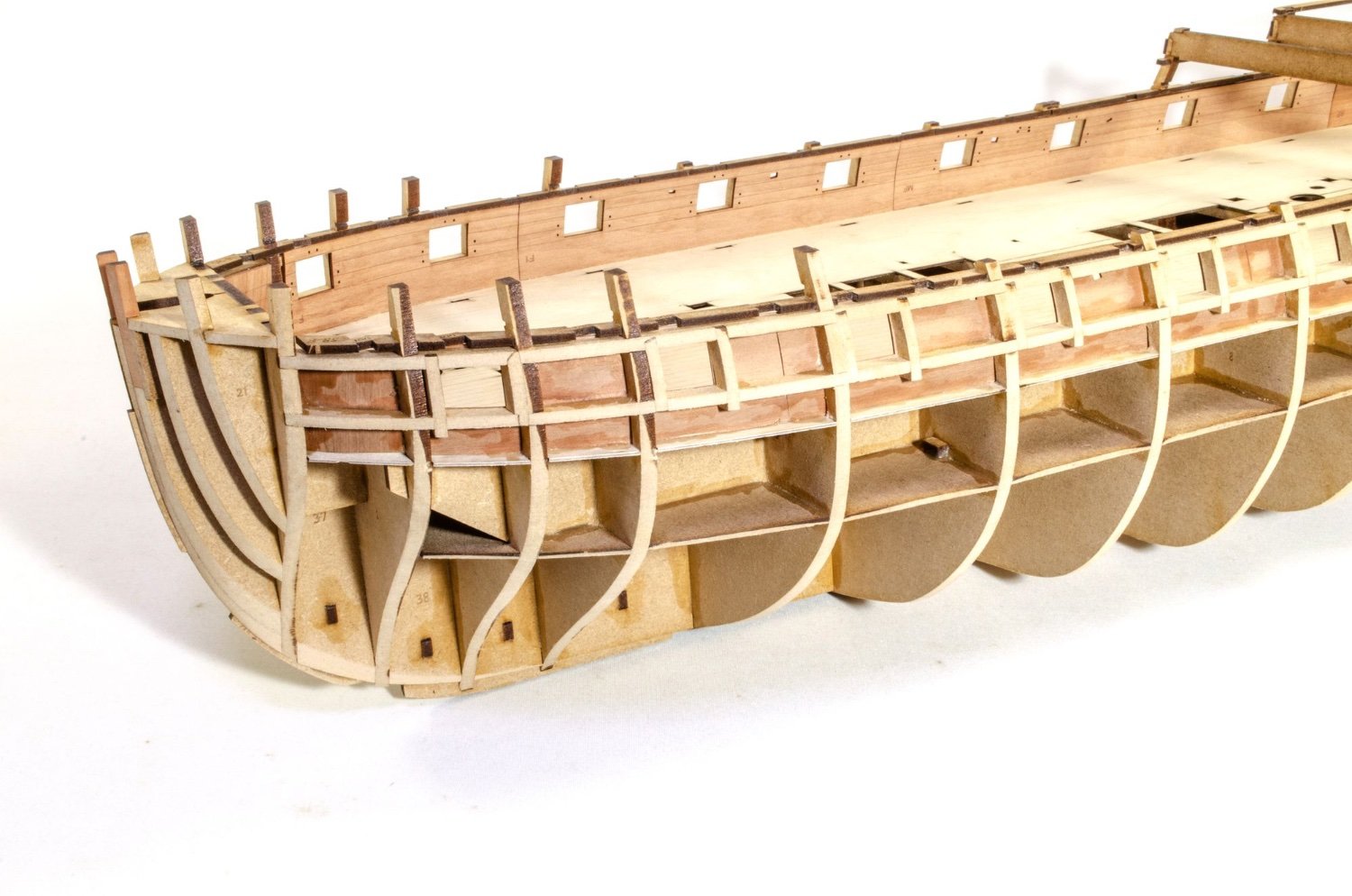
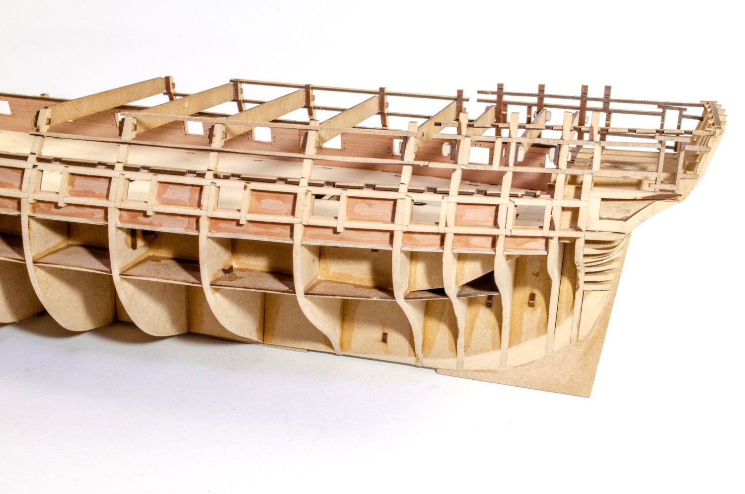
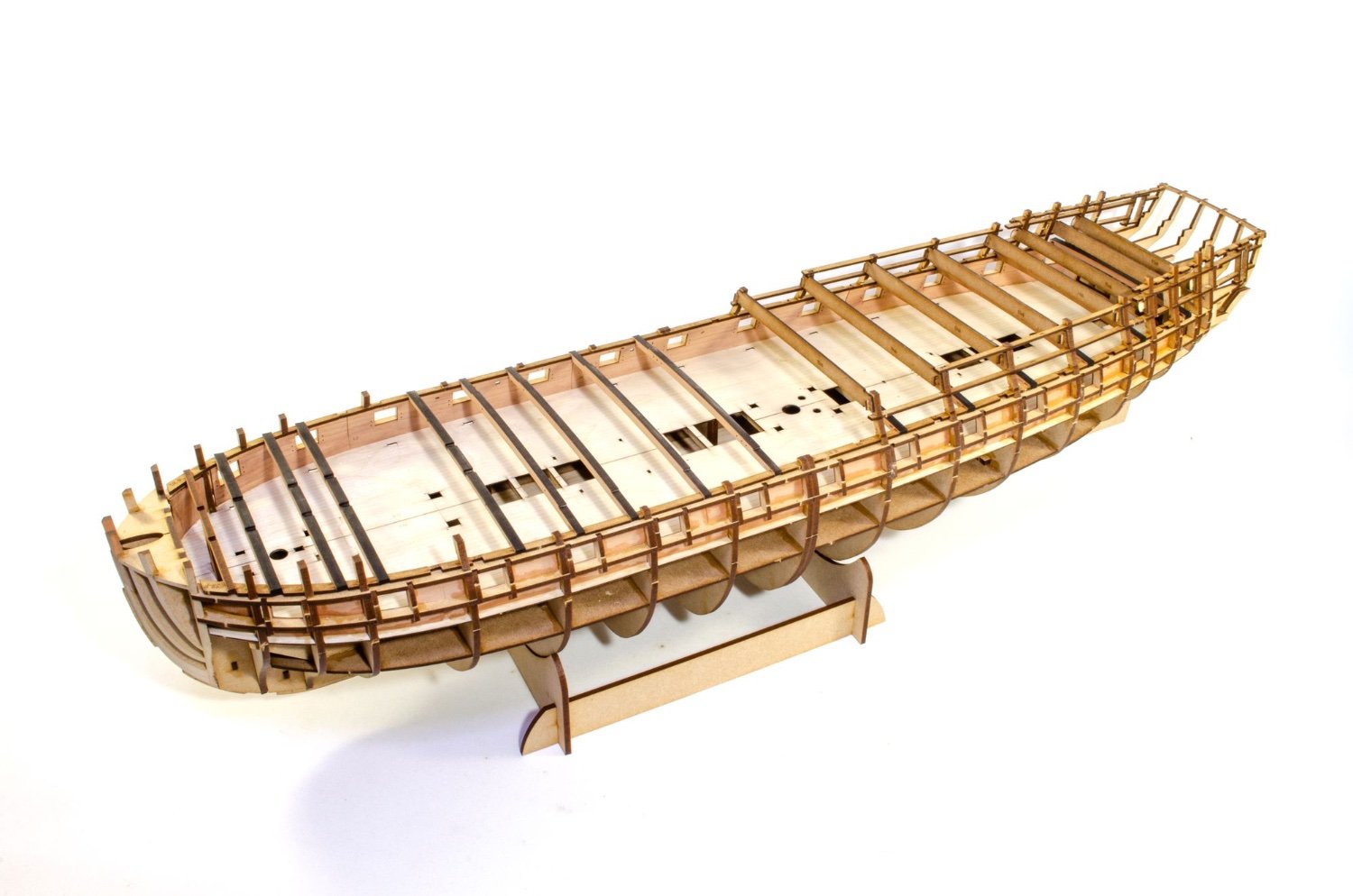
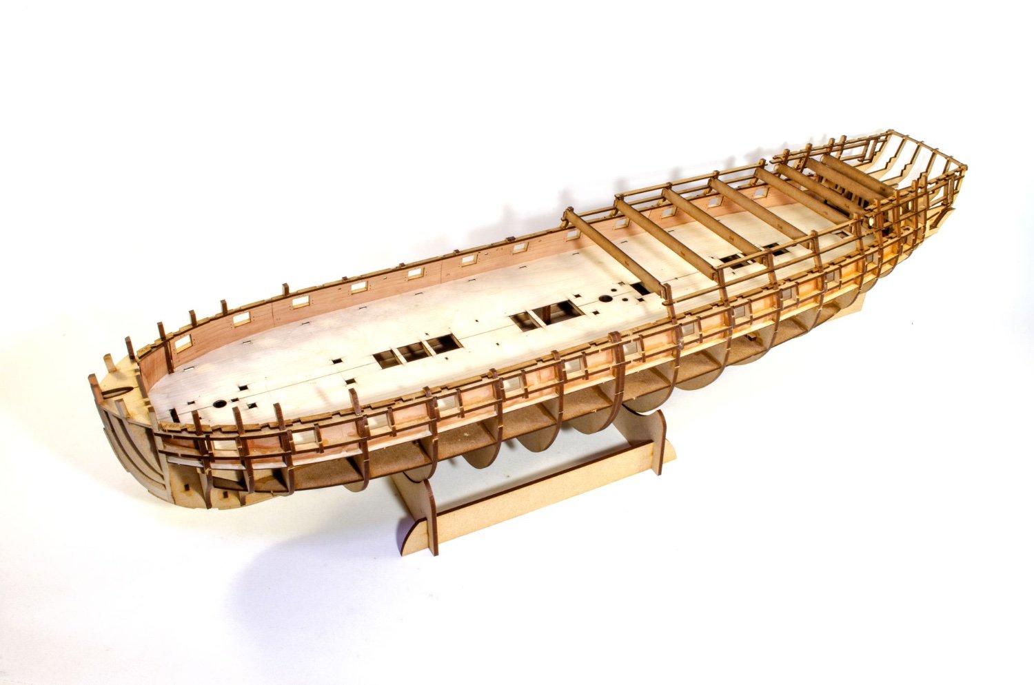
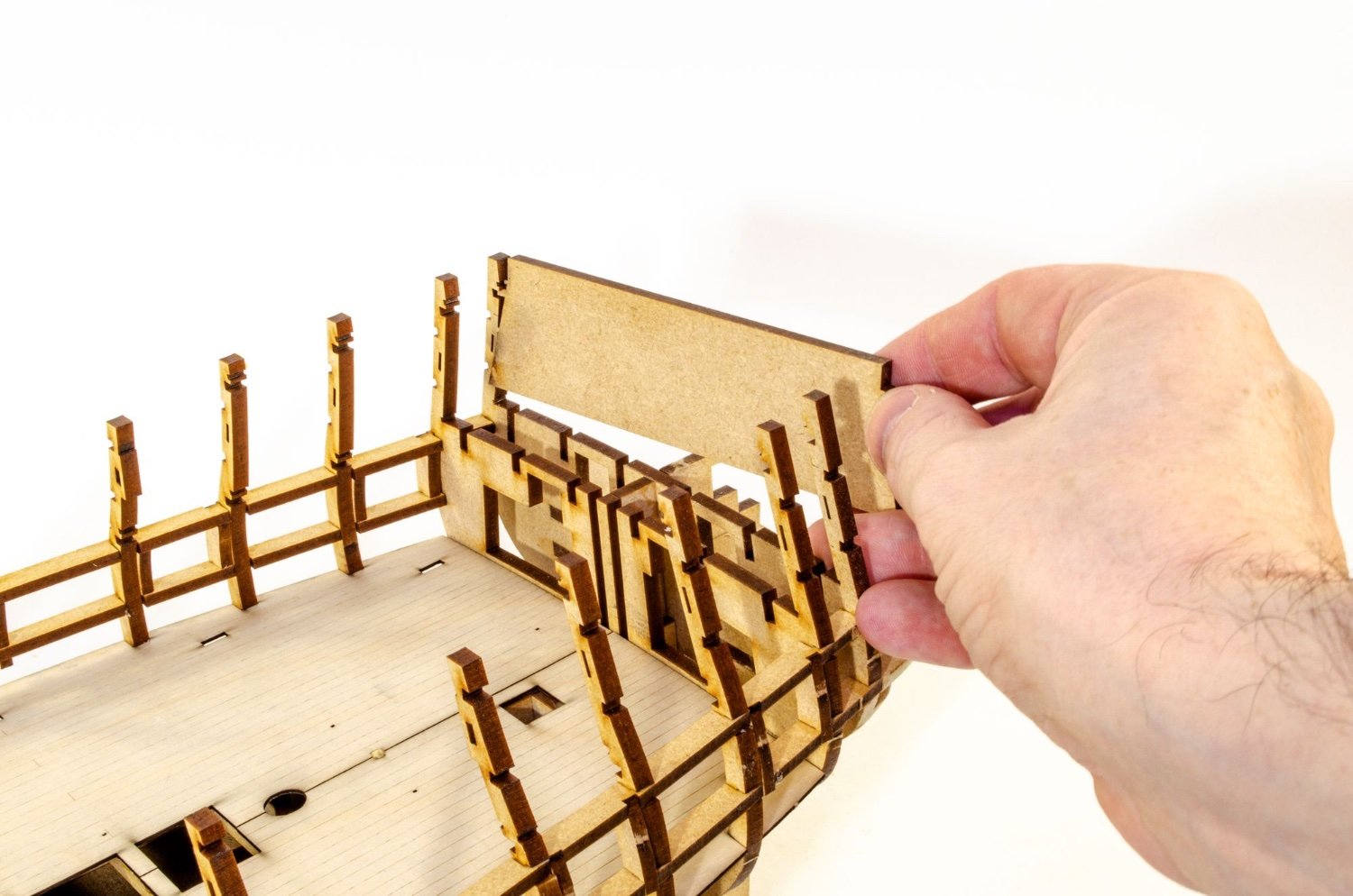
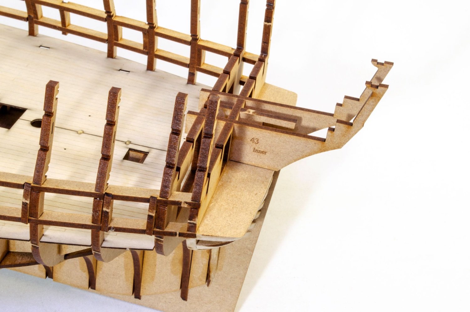
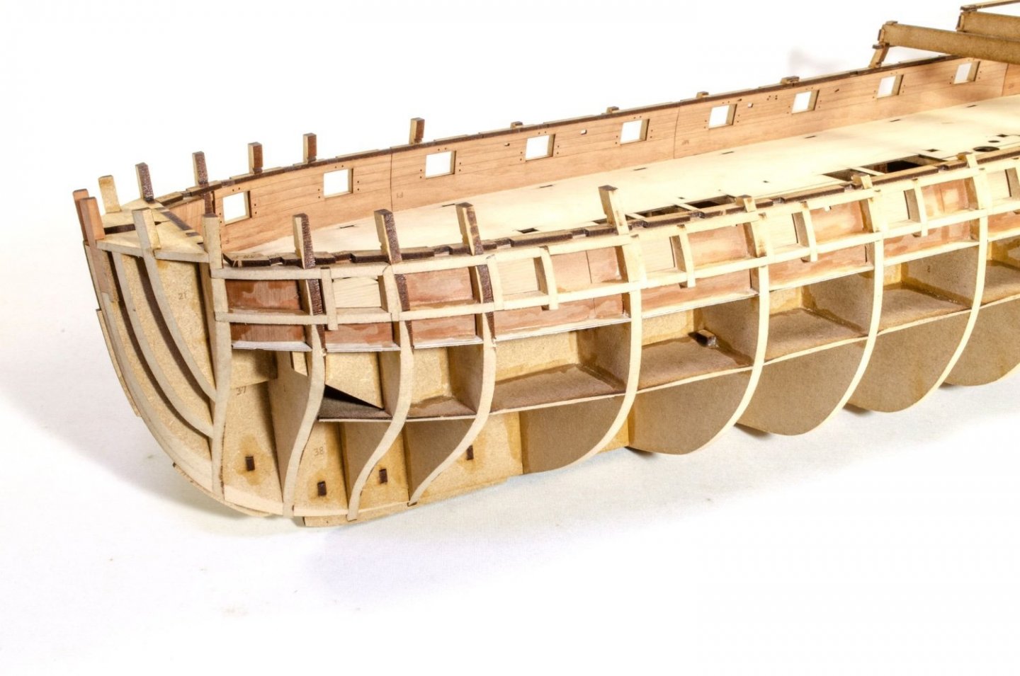
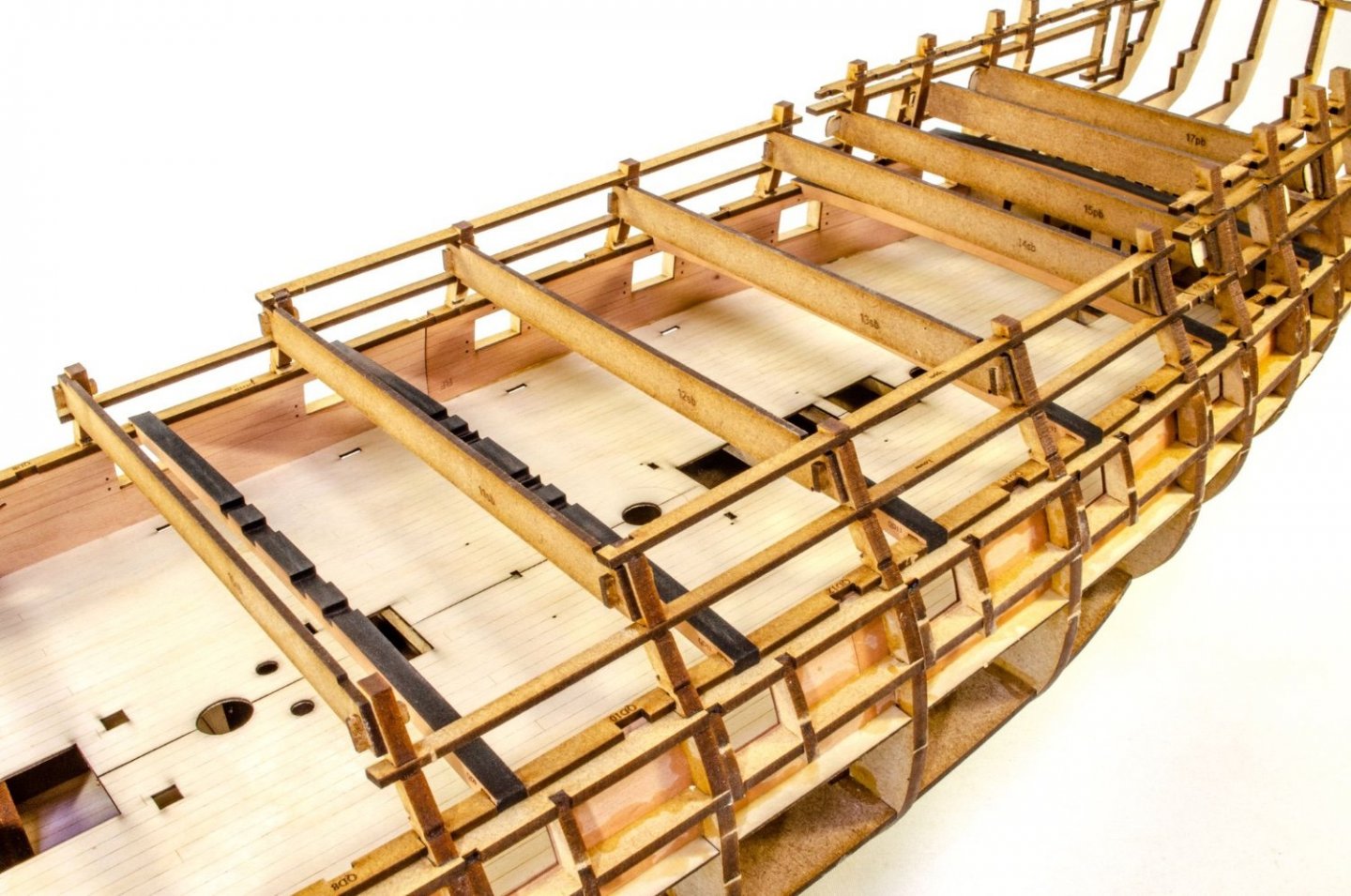
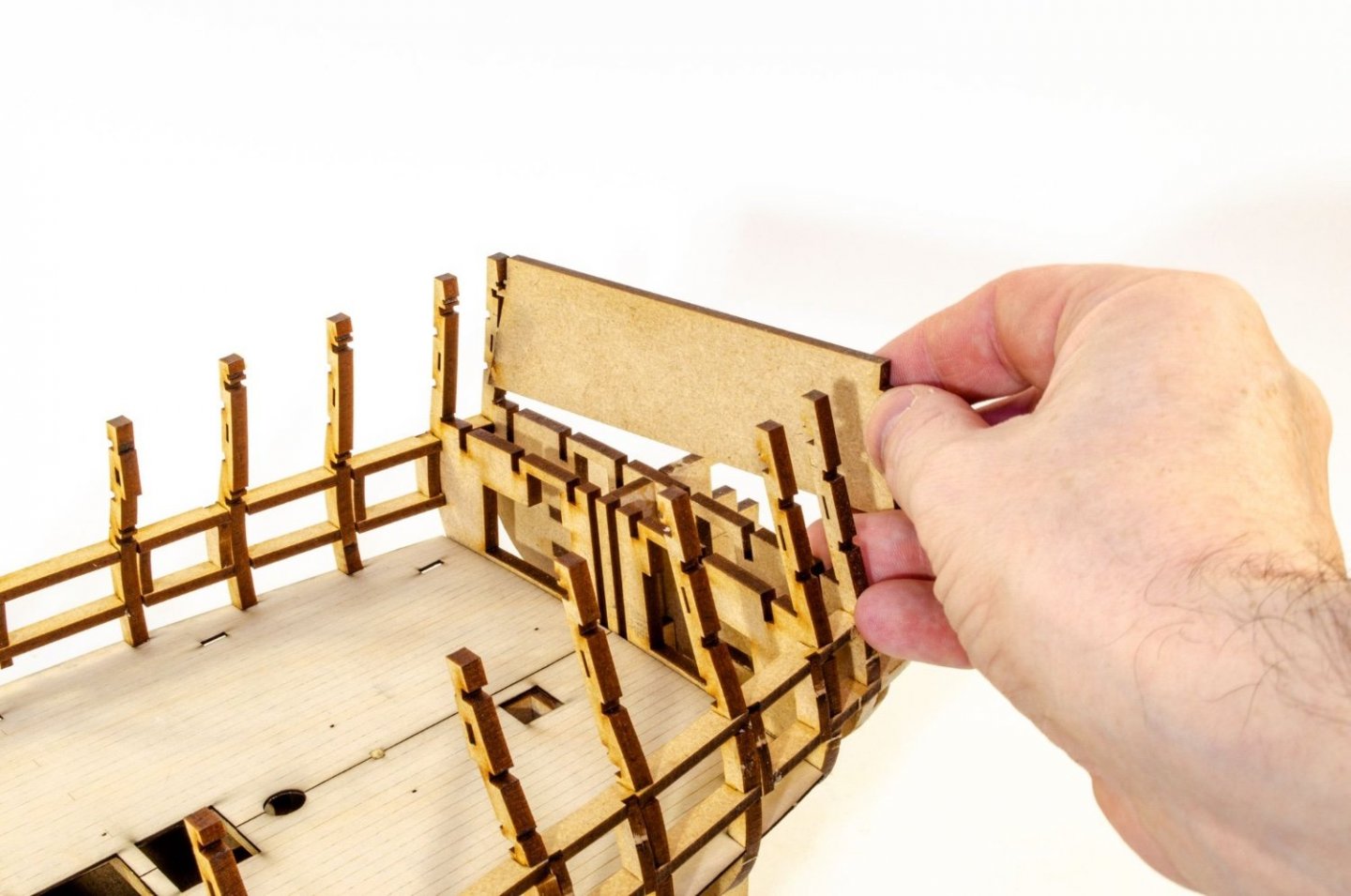
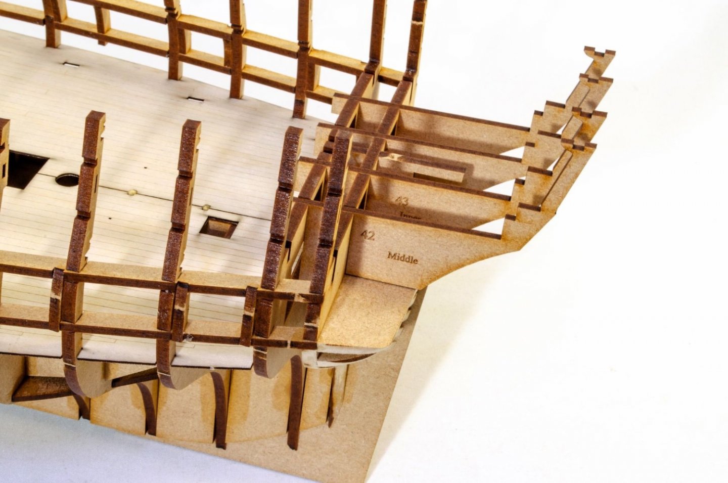
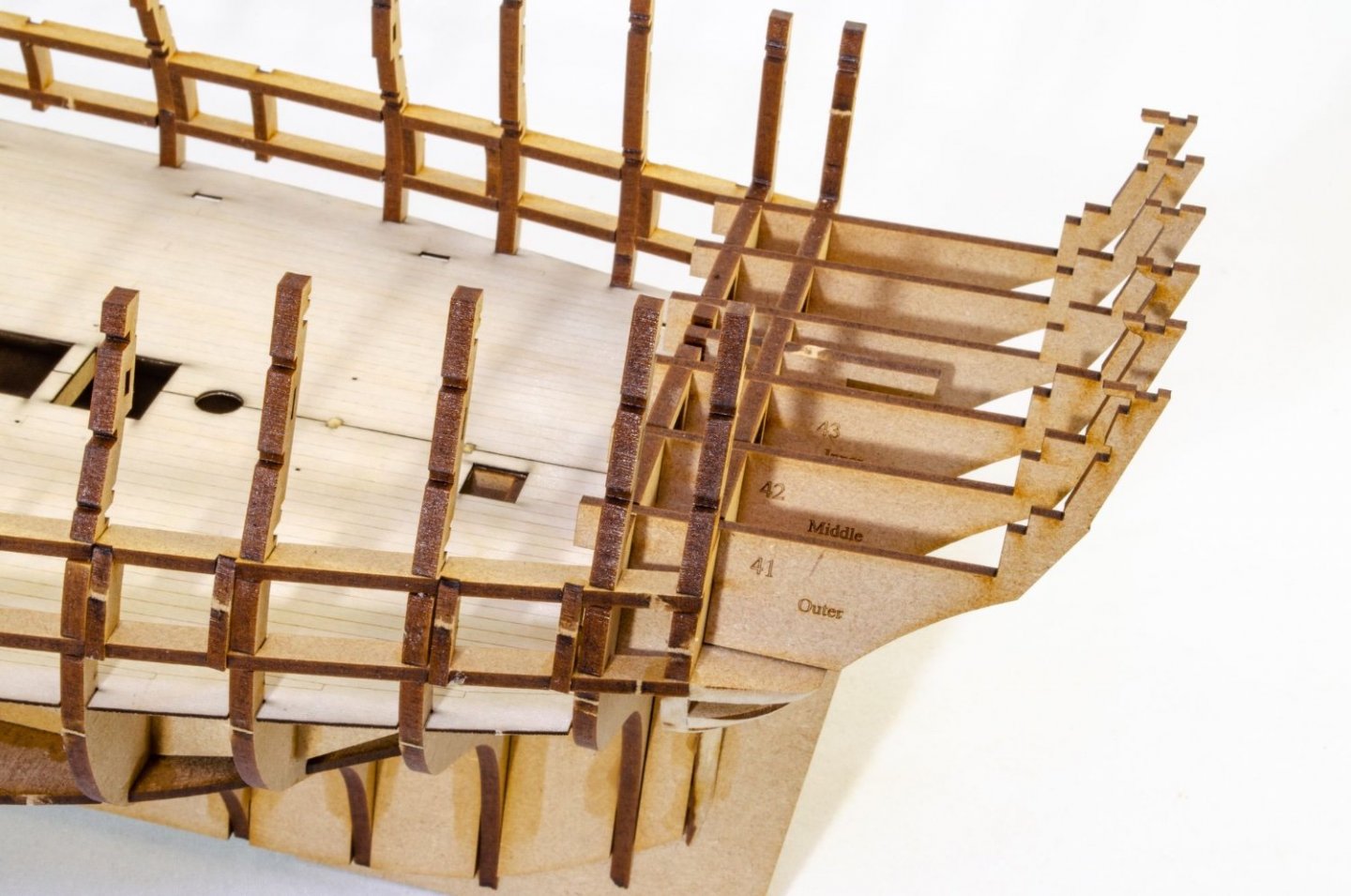
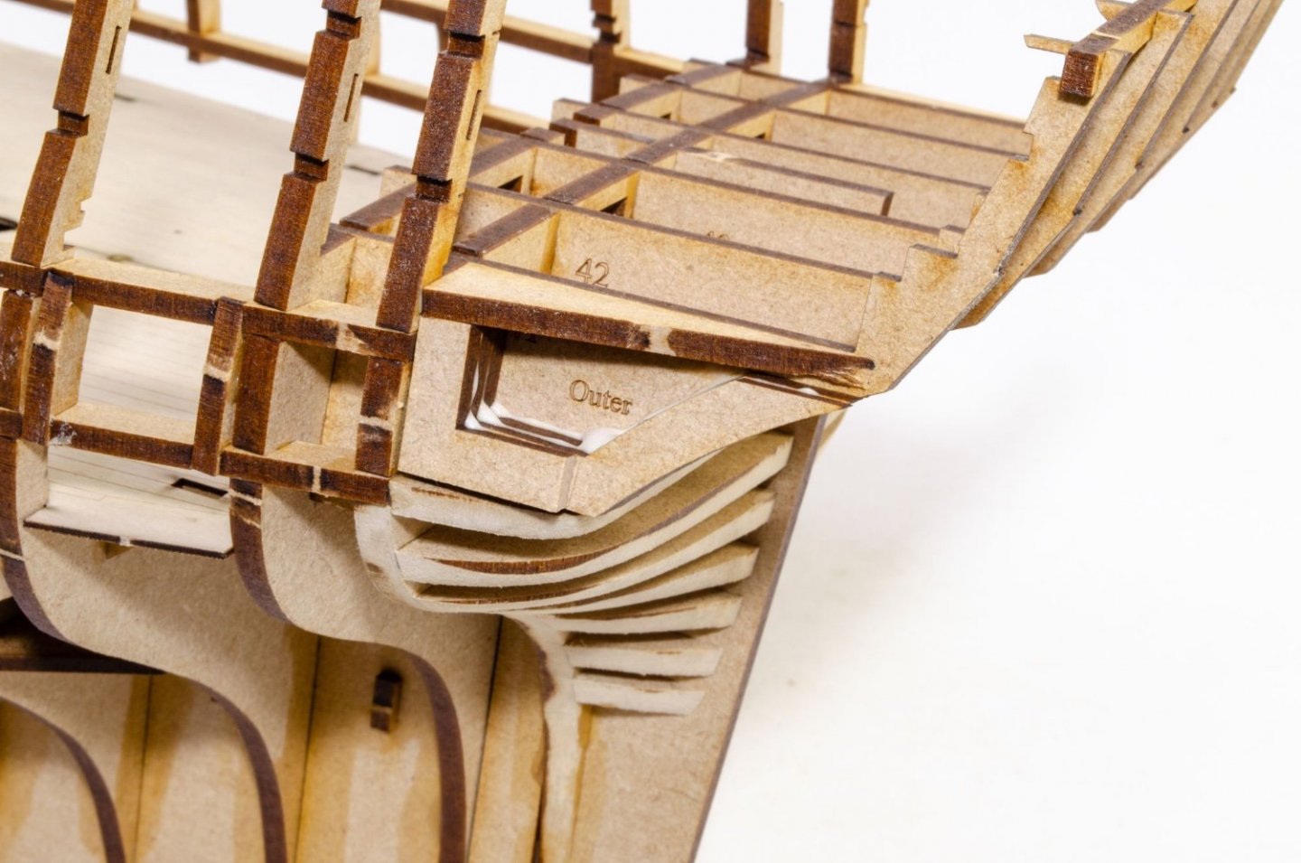
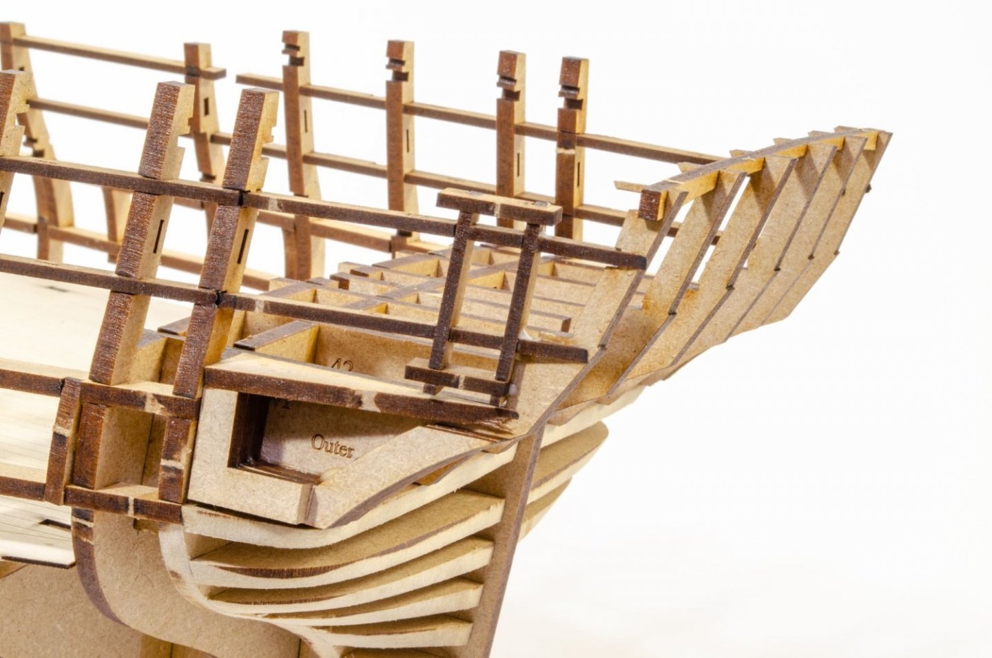
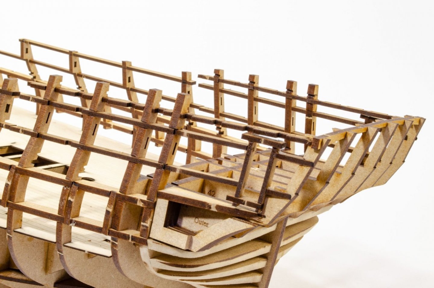
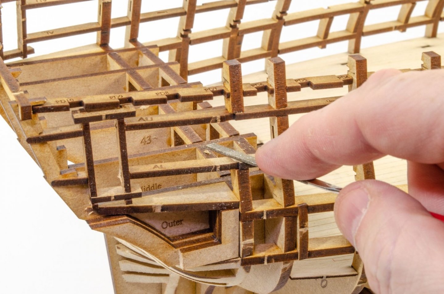
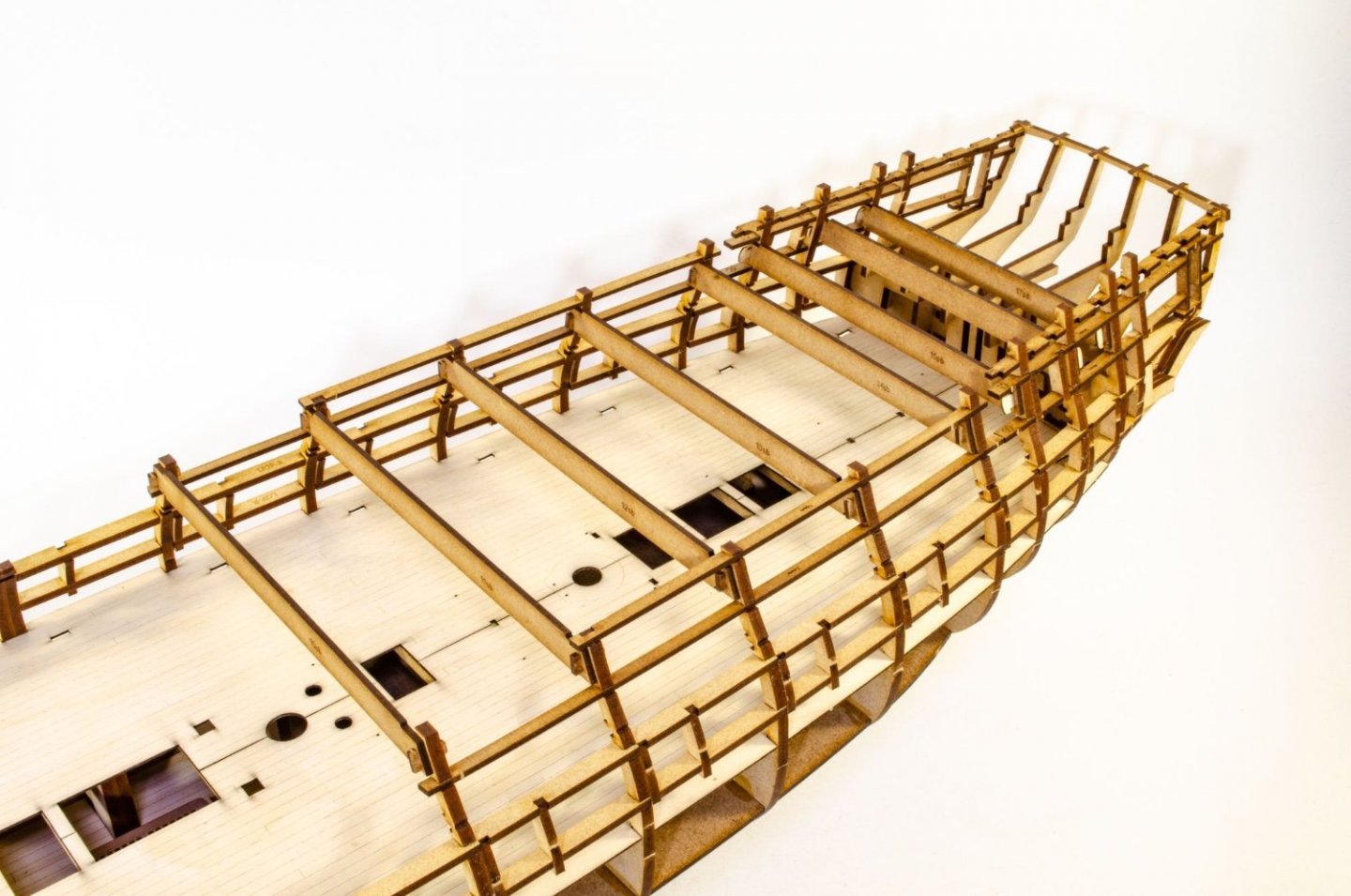
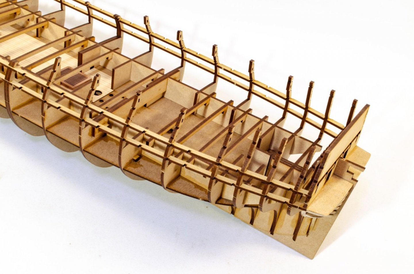
Continuing today's update: Time to get rid of that blank section in the last bulkhead. That was there to protect the bulkhead while work was being done on it with shaping the stern. A gentle twisting removes this from the hull. Time for the stern timbers to be fitted. These slot across the rear two bulkheads, creating the correct angles for the parts. They also sit on the shaped stern upper block. First the inners, then the middles, followed by the outers. Some filler blocks are now added to the outside of the outer timbers, creating the rest of the platform and something to plank to also. Those fragile rear bulkhead ears are now bolstered with the addition of more longitudinal strips, all slotted to fit. The gap you see between some of them is to house the fore bulkhead screen. That's designed so you get zero gaps. You'll see that later in the build. Door frames are added from the captain's cabin to where the quarter galleries will eventually fit. Once dry, the inner horizontal parts of the frames are cut out. Part of bulkhead 18's ear is now cut out as this is the only one that would obstruct the gun port. That is sawn out and filed flush before the last gun port frames are glued in. To create a rigid structure for fairing, the rear of the hull has some temporary MDF sections that are held in place with pegs. These are totally solid and shouldn't come loose. And that is it for today. I'm whacked!


- 473 replies
-
- 50
-
-
-
- Indefatigable
- Vanguard Models
- (and 1 more)
-
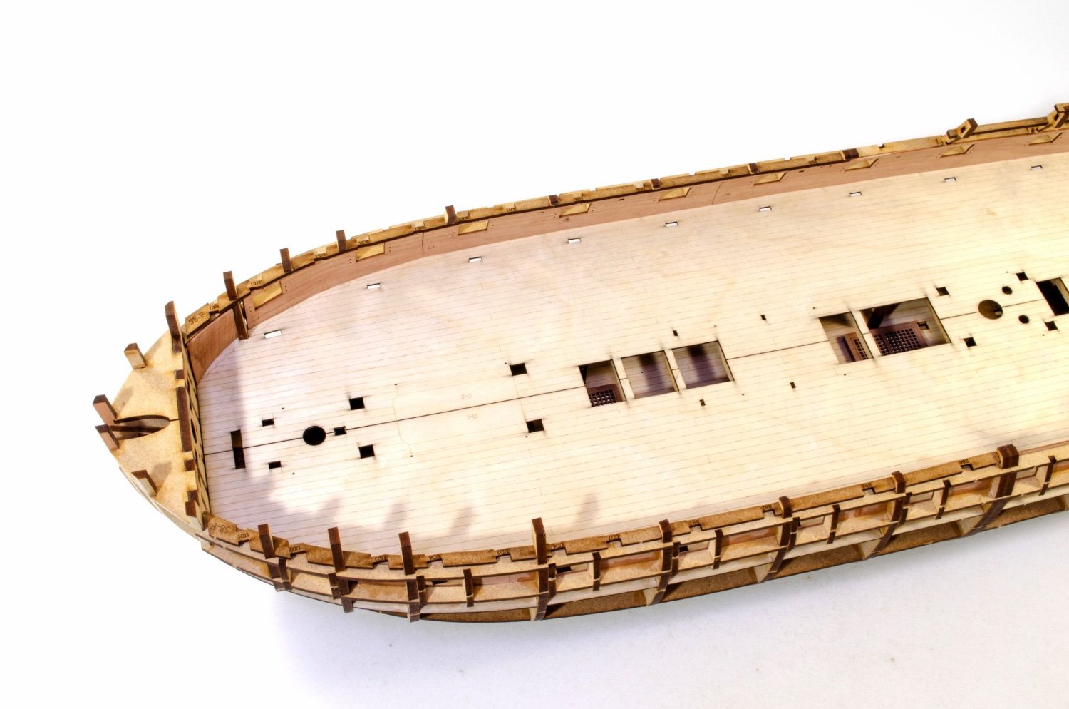
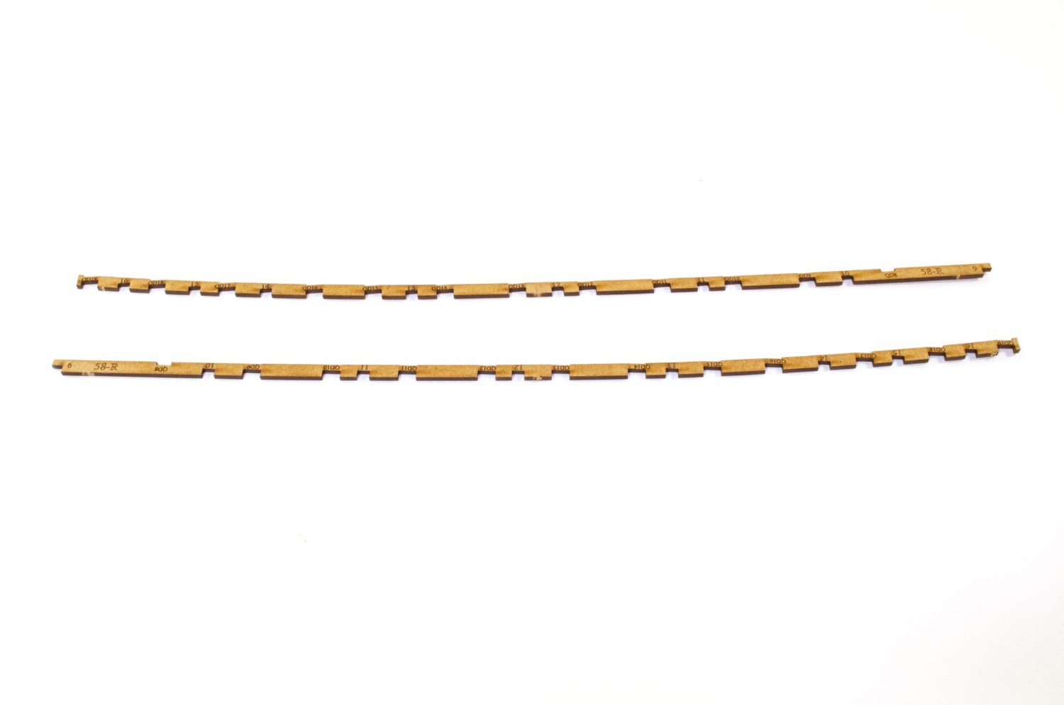
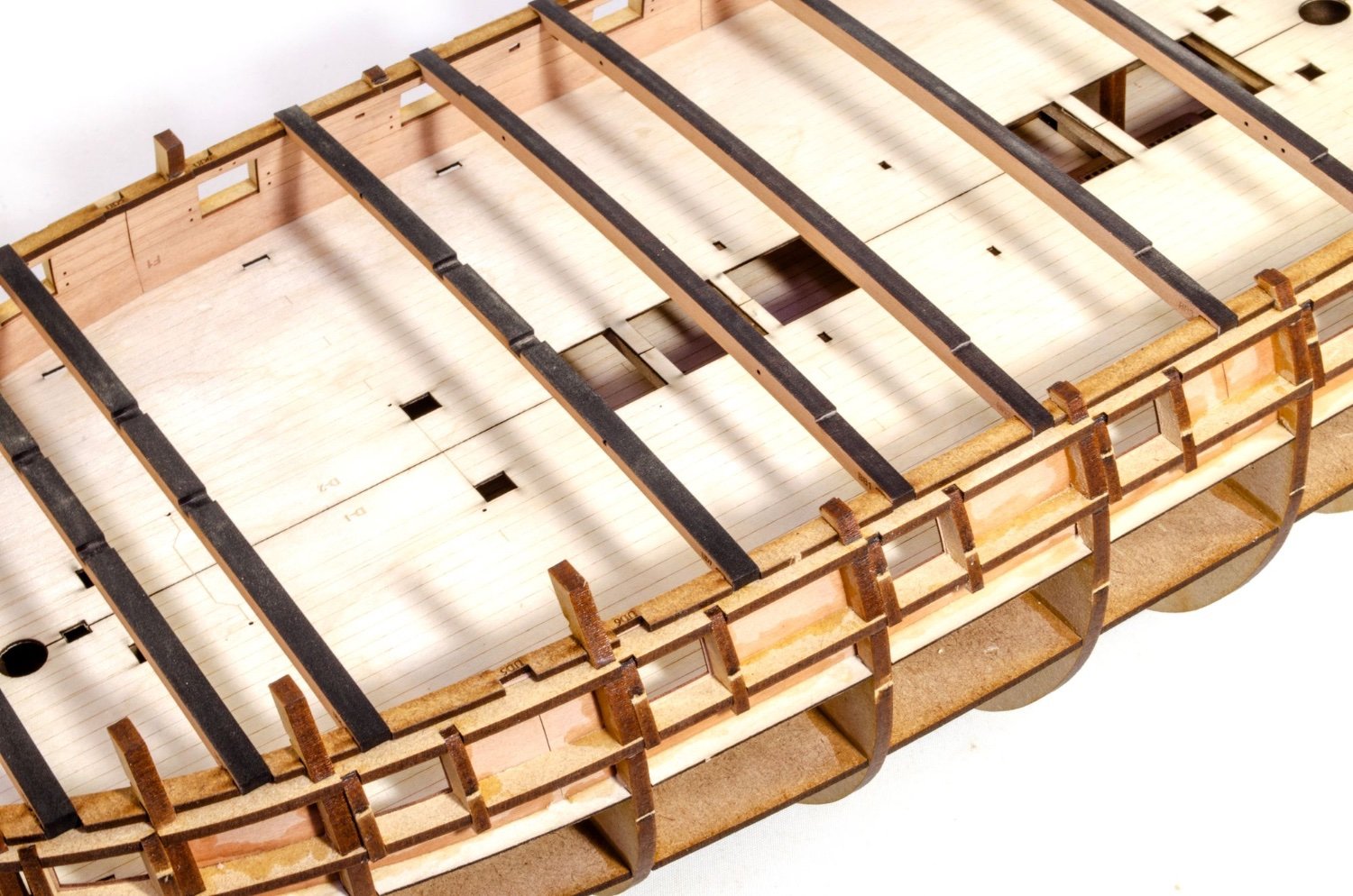
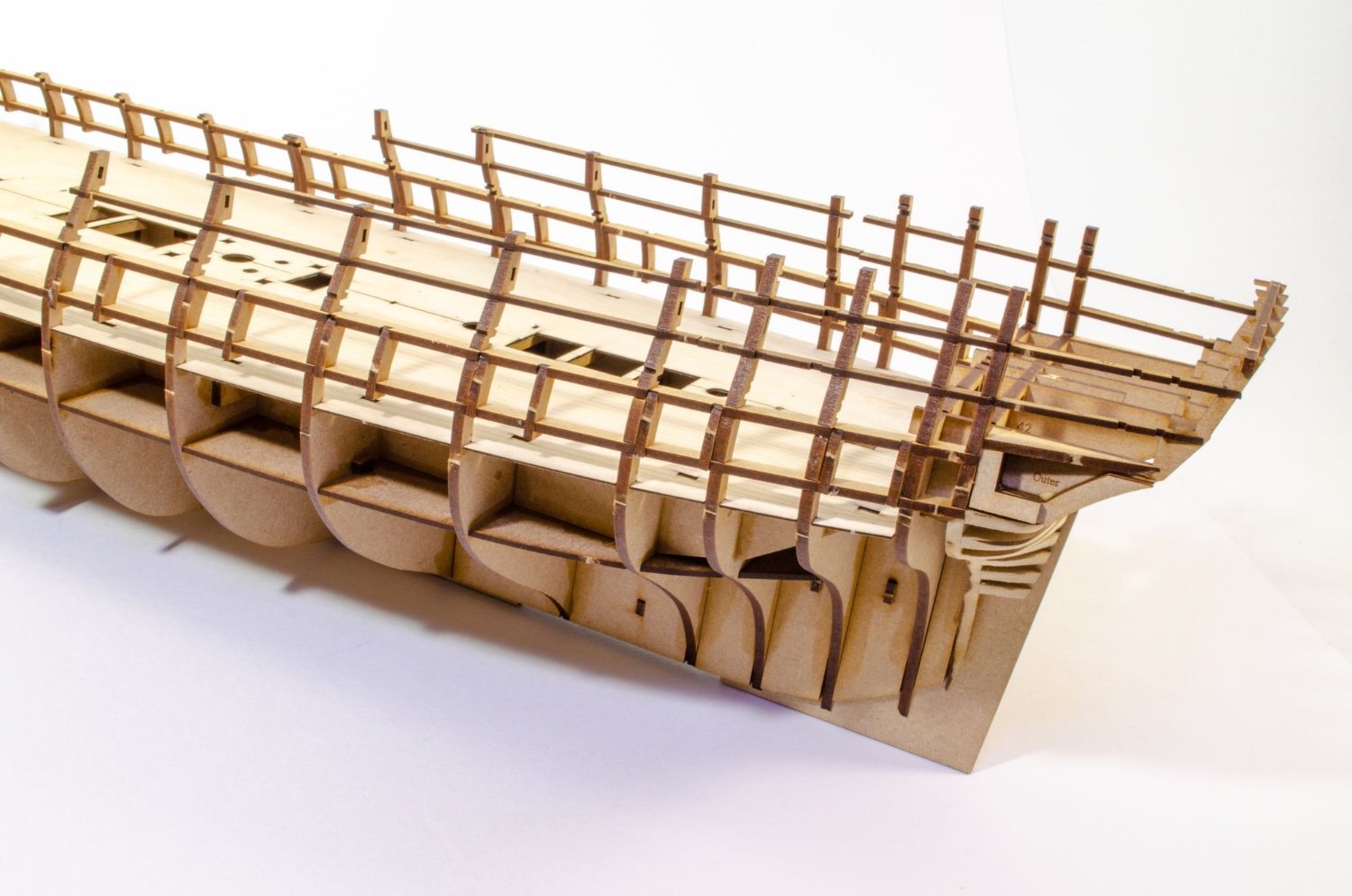
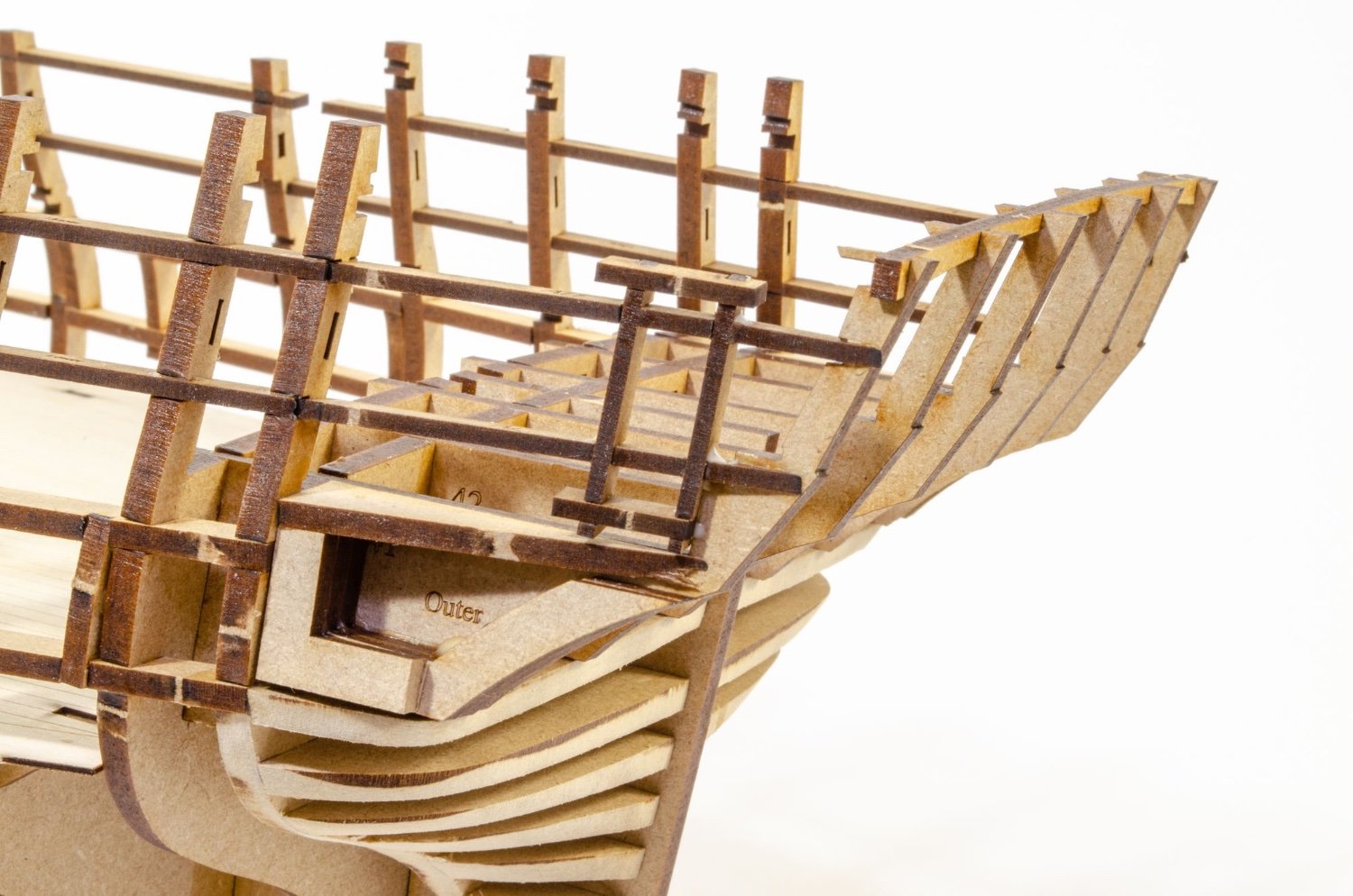
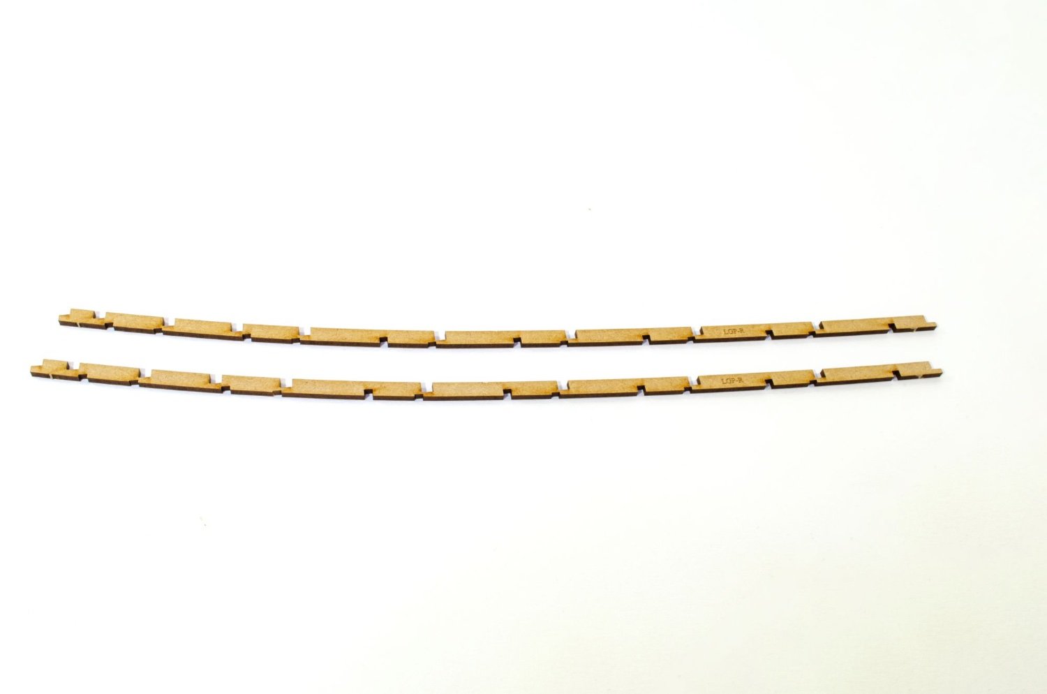
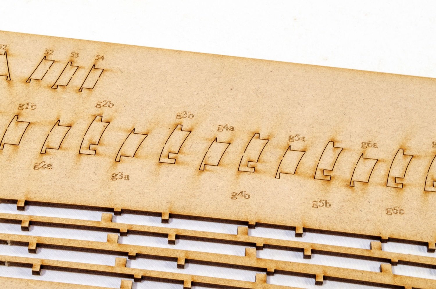
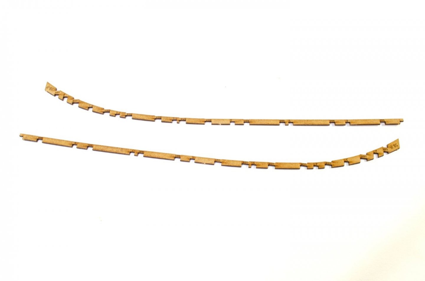
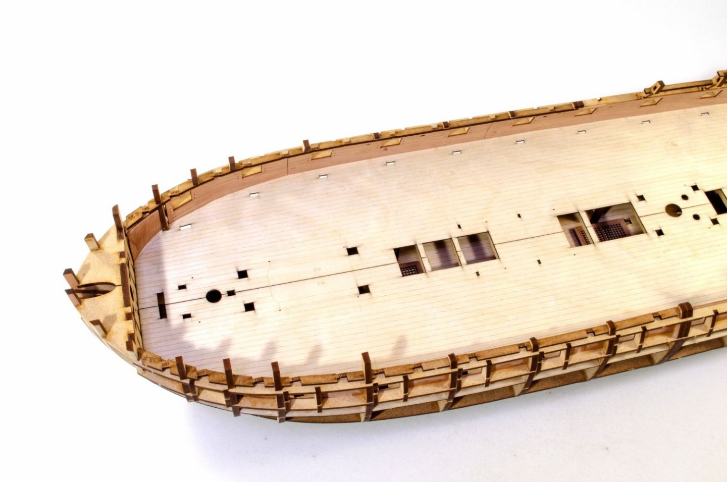
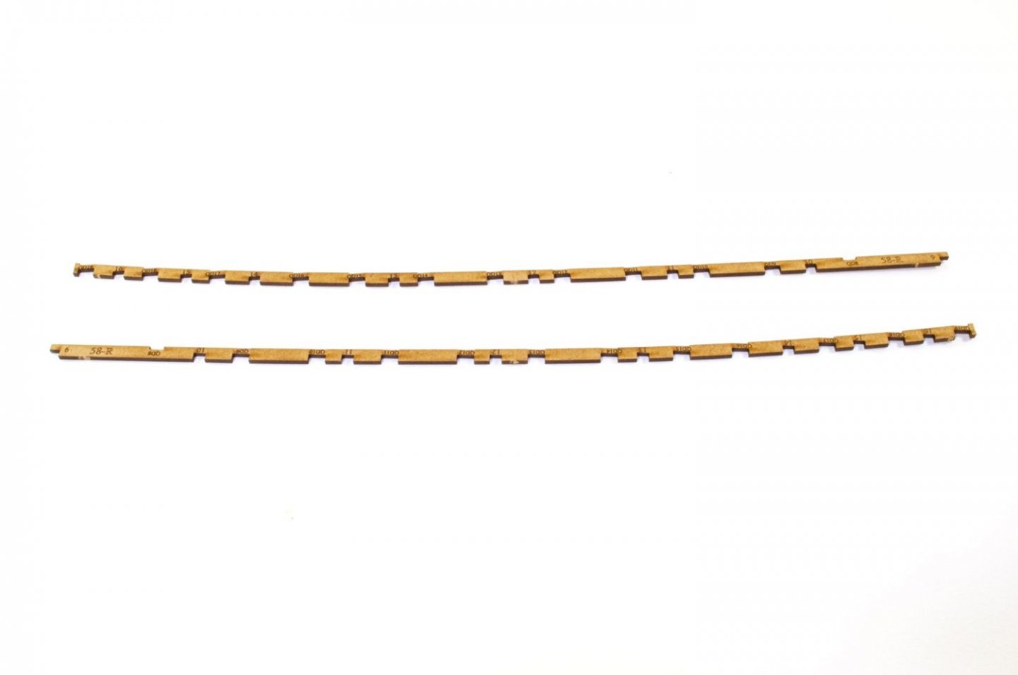
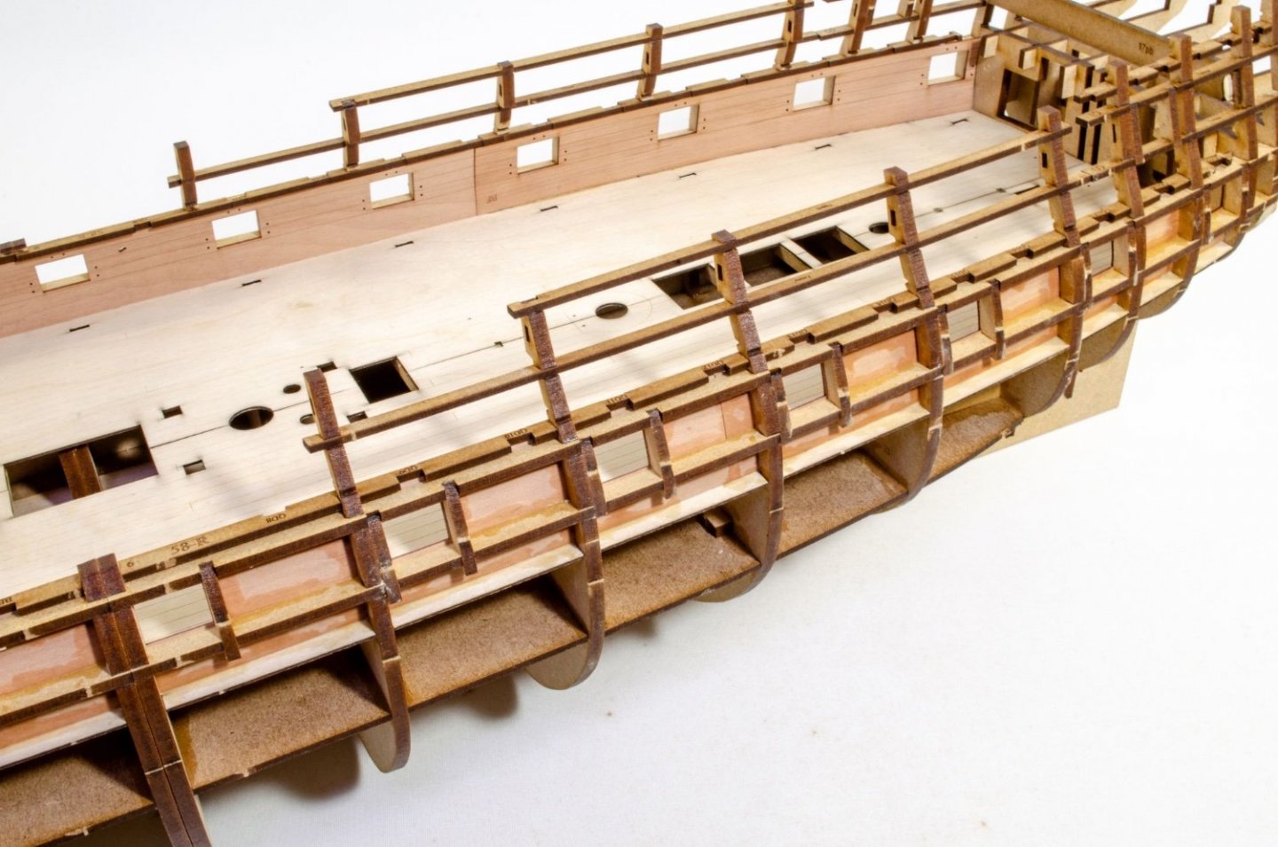
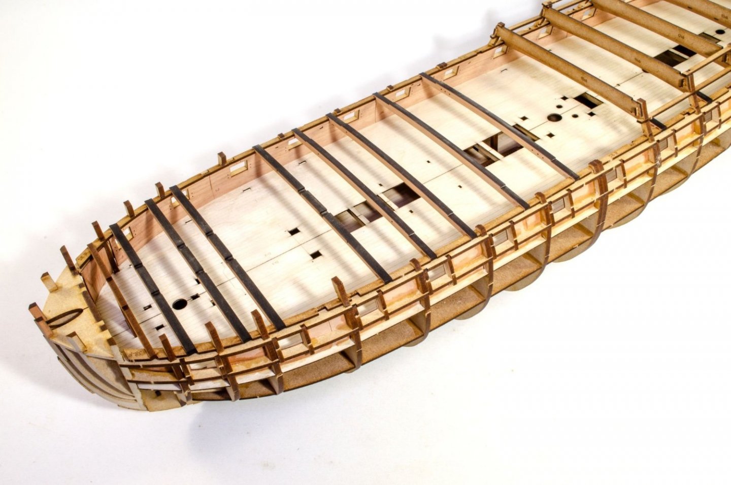
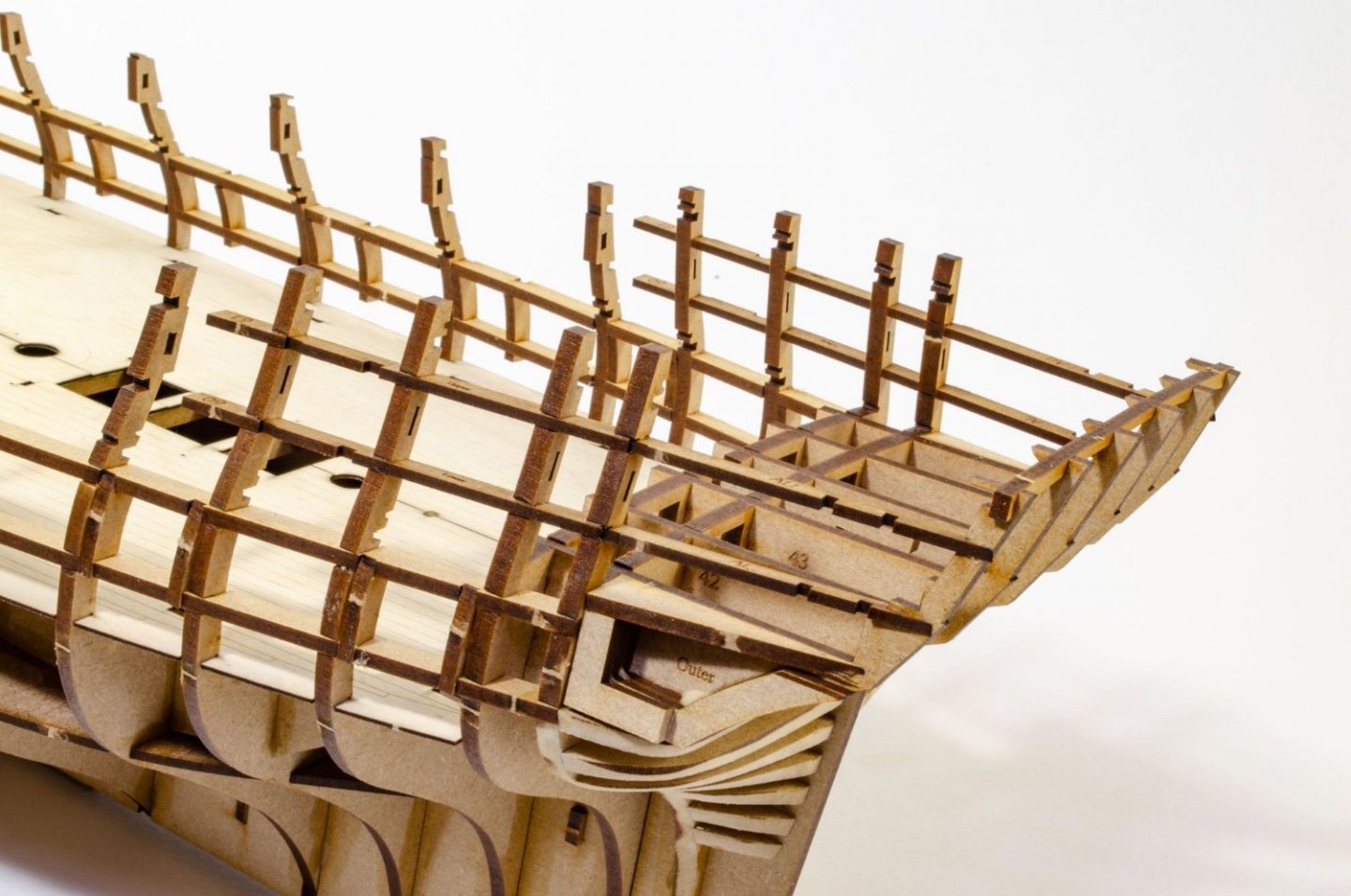
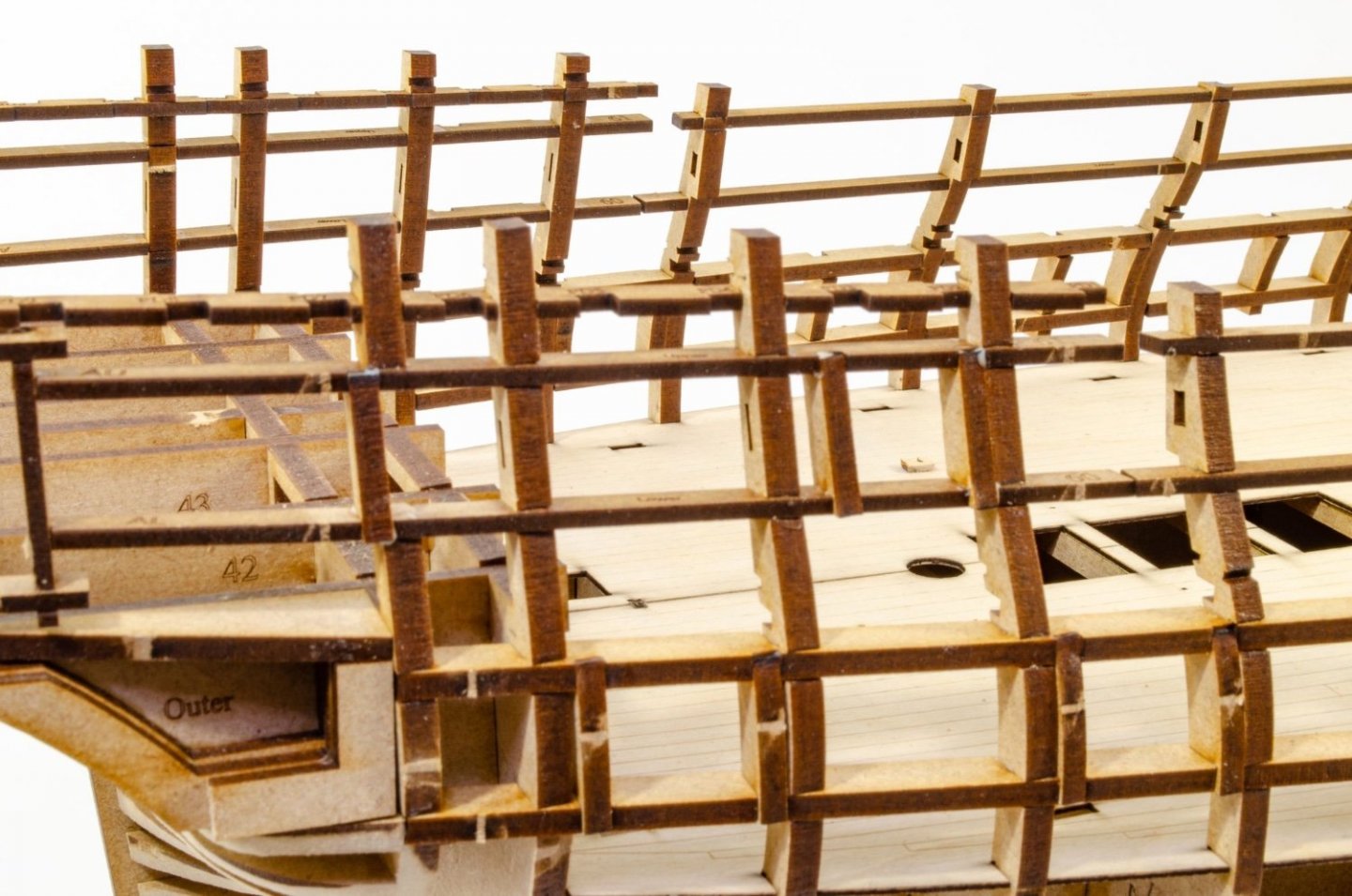
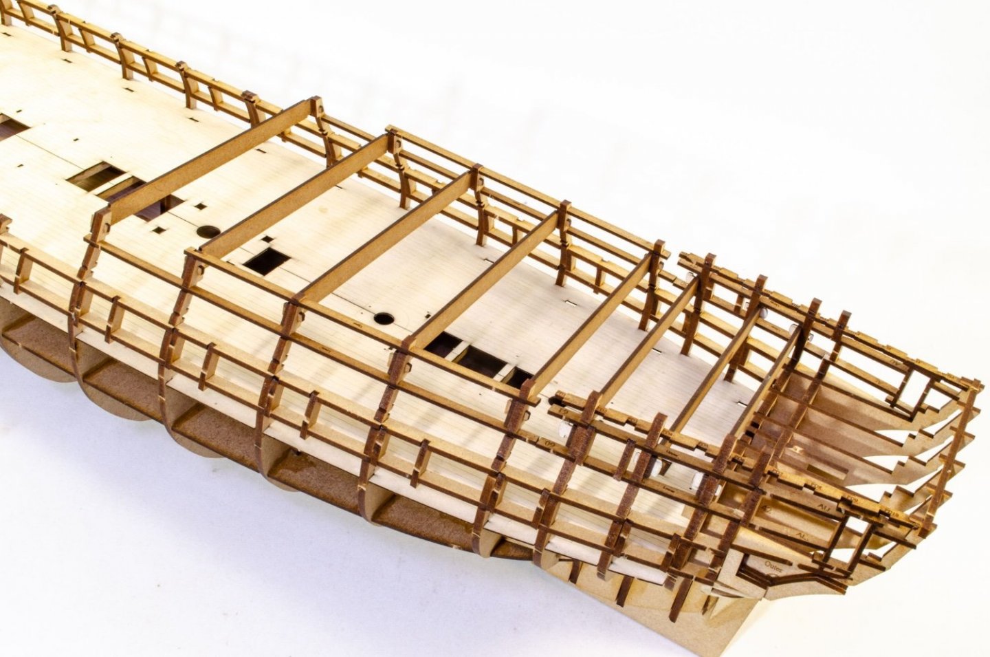
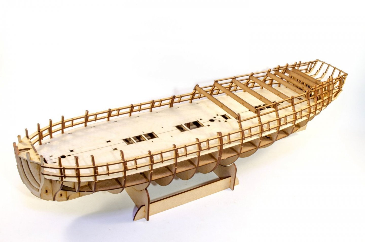
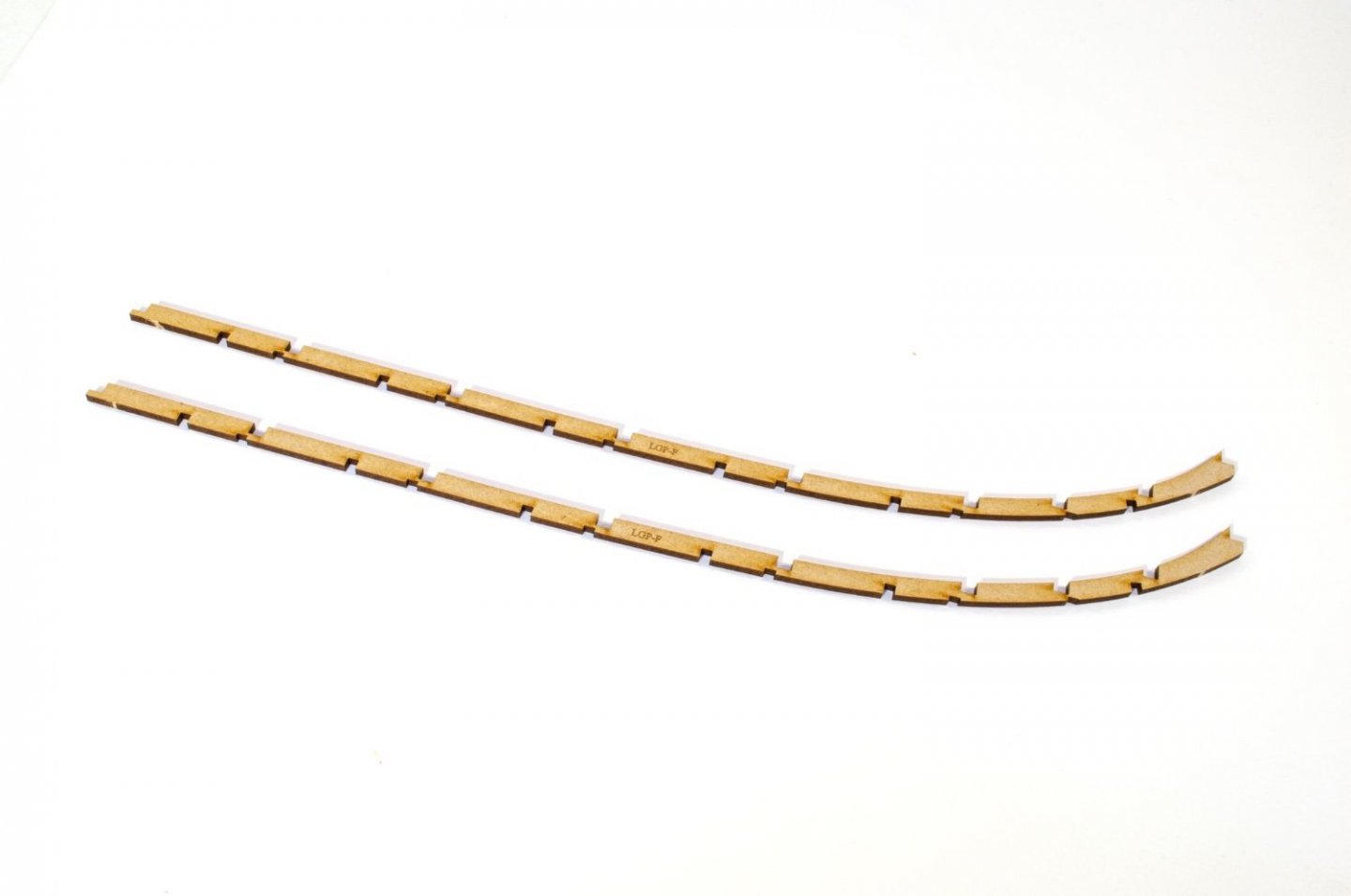
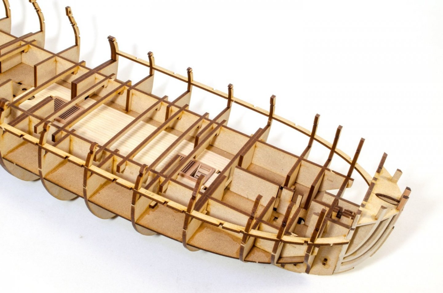
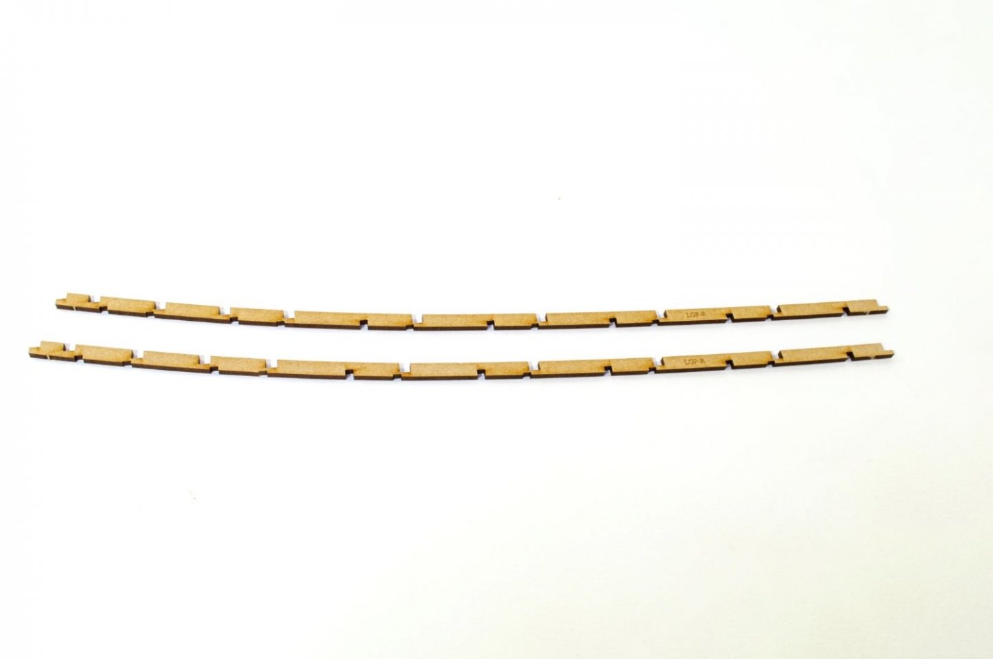
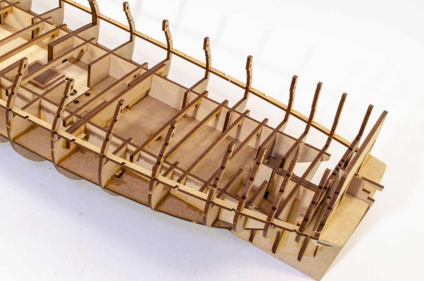
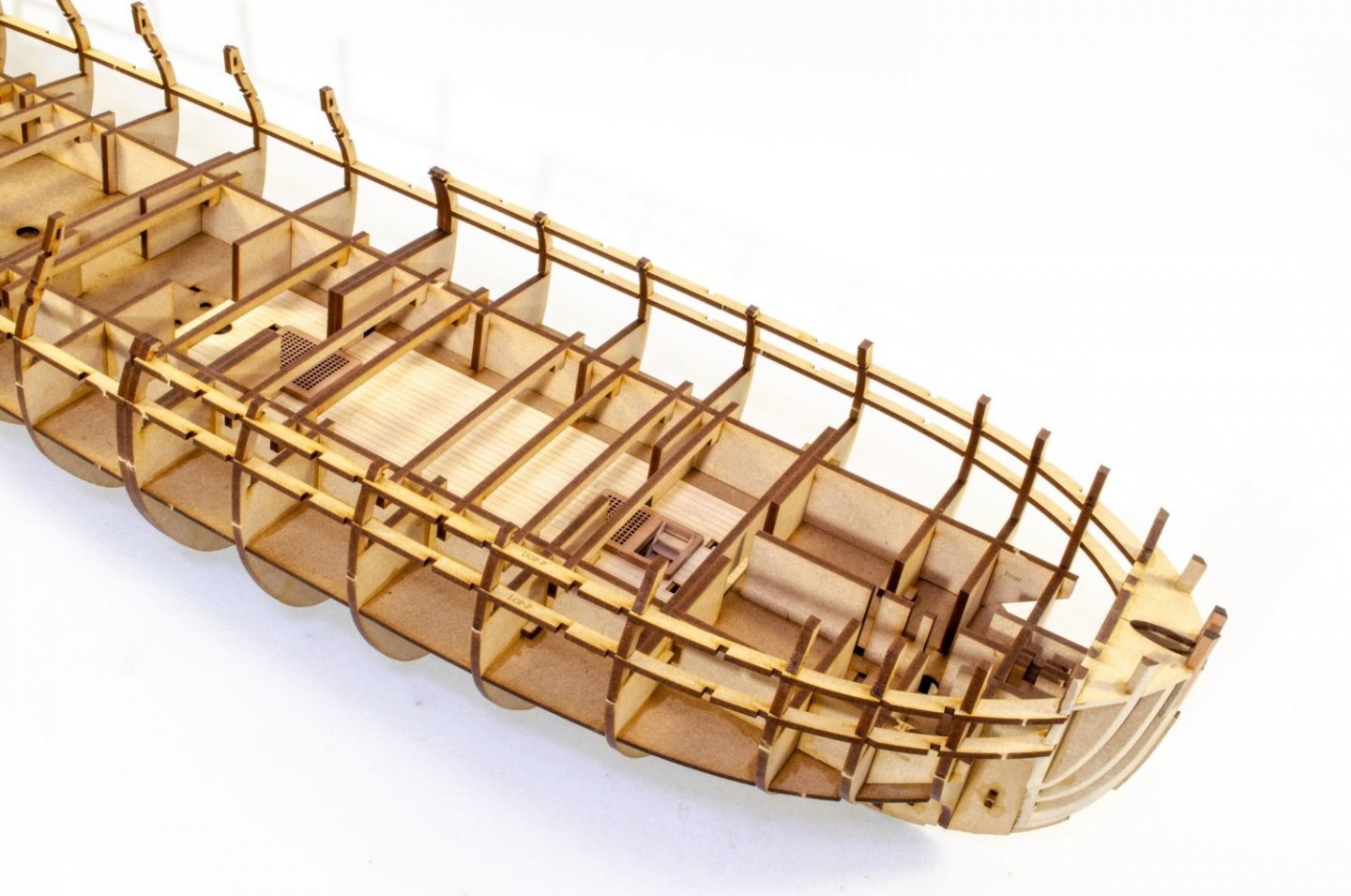
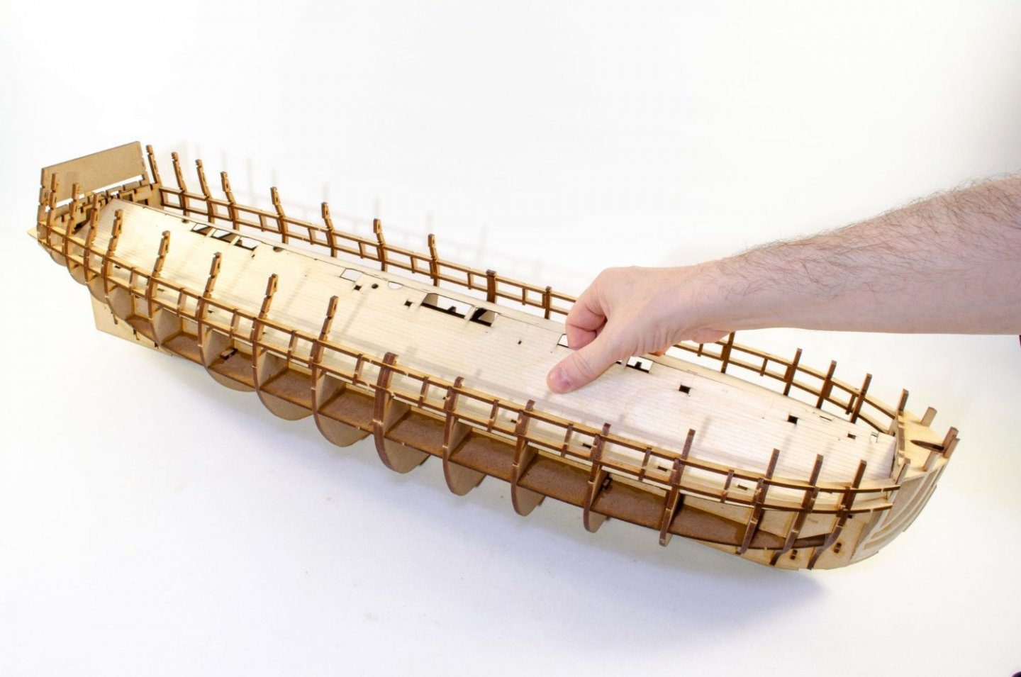
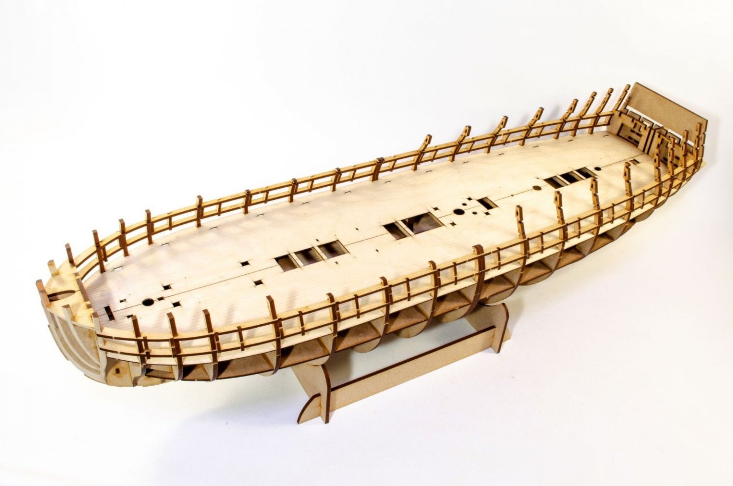
Time for another Lego update. Next job was to bolster those bulkhead ears by adding the gun ports. As with Sphinx, these are built into the frame. The main gun deck longitudinal frames lock into the bulkheads and comprise two parts upper per side, and two parts lower. Lower in first of course. The vertical gun port frames now need to fit in. These are all specific, to suit the curve of hull. Each port has two verticals apart from #7, as that one uses the side of a bulkhead for the other vertical. The main gun deck ply layer is pre-engraved to help you with laying the planks. It's also supplied in halves, to make it easier to fit. Both deck halves are turned upside down and a strip of narrow tape is applied full length, and then the various openings cut out. The deck is then turned over and bent down the tape hinge before being glued into place. Deck edges lock into slots in the base of the bulkhead ears, so there's no problem with it popping up. It's just a case of making sure it's glued down across the deck beams and then weighted down while it dries. No need to pin anything here.

- 473 replies
-
- 31
-
-
-
-
- Indefatigable
- Vanguard Models
- (and 1 more)
-
That is just gorgeous! Thanks for sharing that 🤩
-
It's a no-brainer! Ply wouldn't really work on this as the tolerances needed for so many Lego slots would throw the construction out, especially the framed gun ports. MDF tolerances are much tighter.
- 473 replies
-
- 16
-
-
- Indefatigable
- Vanguard Models
- (and 1 more)