James H
-
Posts
6,135 -
Joined
-
Last visited
Content Type
Profiles
Forums
Gallery
Events
Everything posted by James H
-

Rivets?
James H replied to Nirvana's topic in Painting, finishing and weathering products and techniques
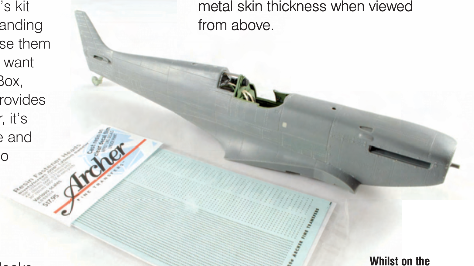
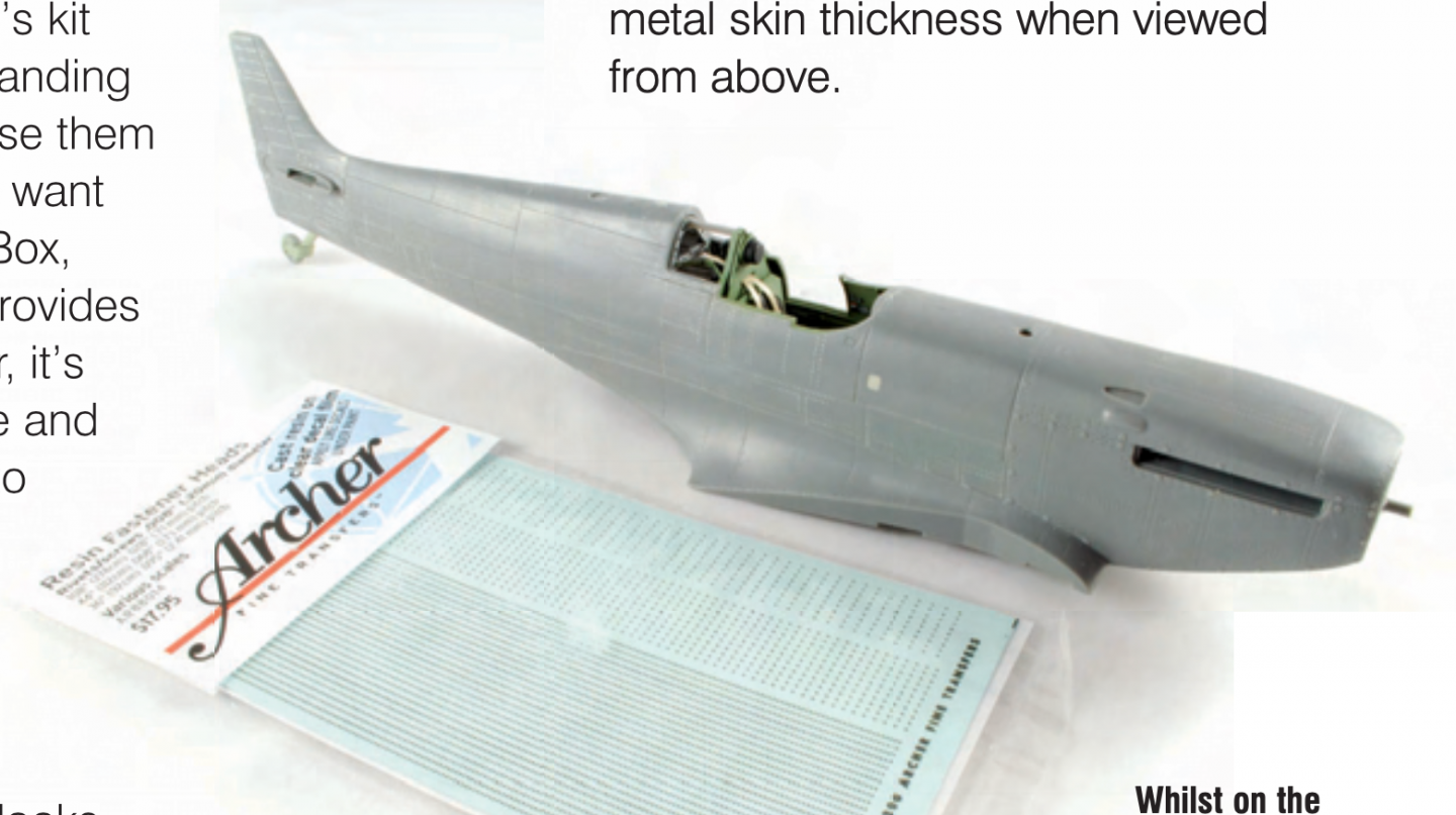
Archer rivet decals are great. Use a decal setting solution for the best results as they help the 3D glue dot adhesive really grip the surface. From my Spitfire book: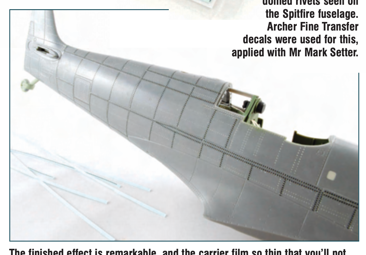
-
I think so. All I've done is the very basic bevelling with the laser lines, leaving some room to play. Where I've been a little tighter to those lines is where they snug up next to the angled template that guides the upper sides. I faired the inside of the hull inside the jig, then stripped the jig to clean it. As soon as the interior of the hull is all built, that is when I'll then fair the exterior.
-
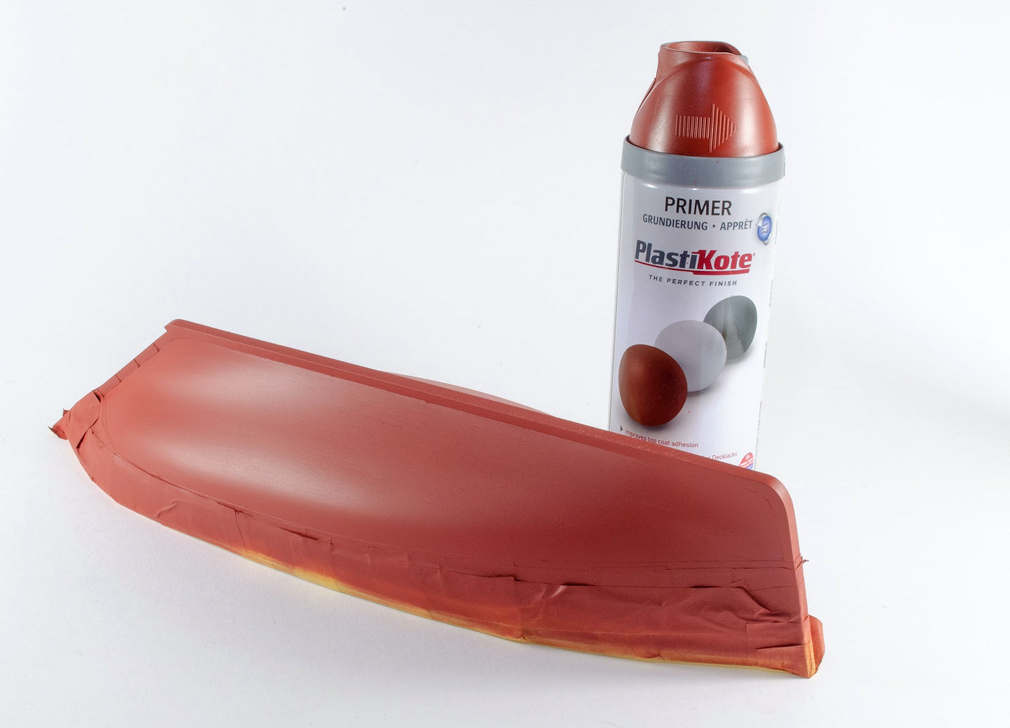
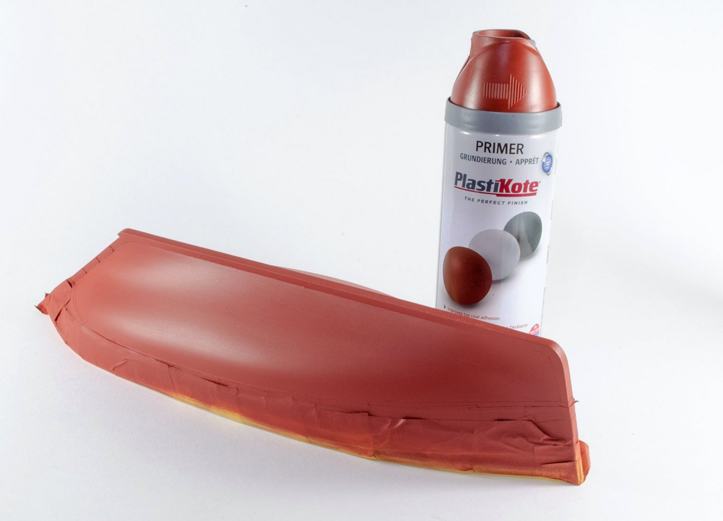
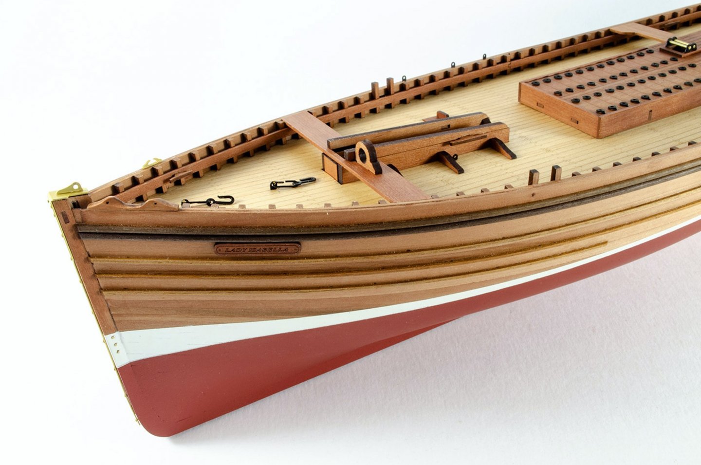
Well that sure looks fine to me For that red, what about Plastikote's aerosol? https://smile.amazon.co.uk/Plasti-kote-25002-400ml-Primer-Oxide/ This is what I used on the undersides of my Fifie and Zulu:
-
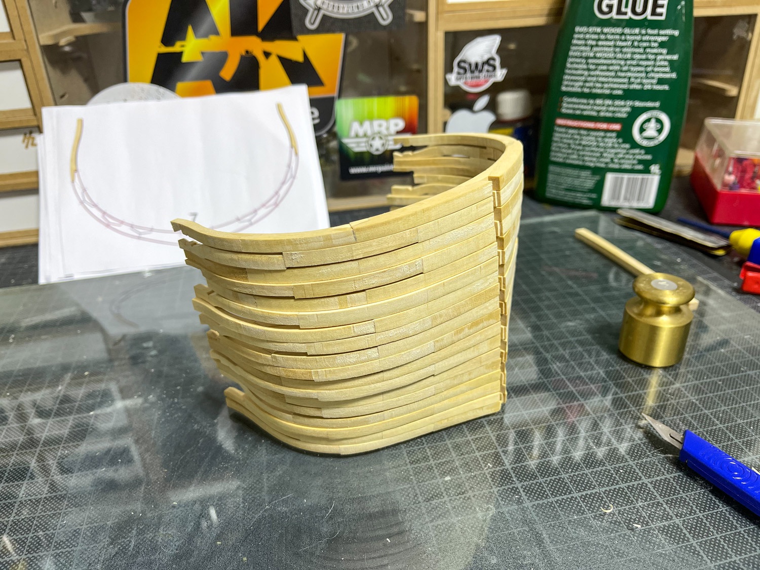
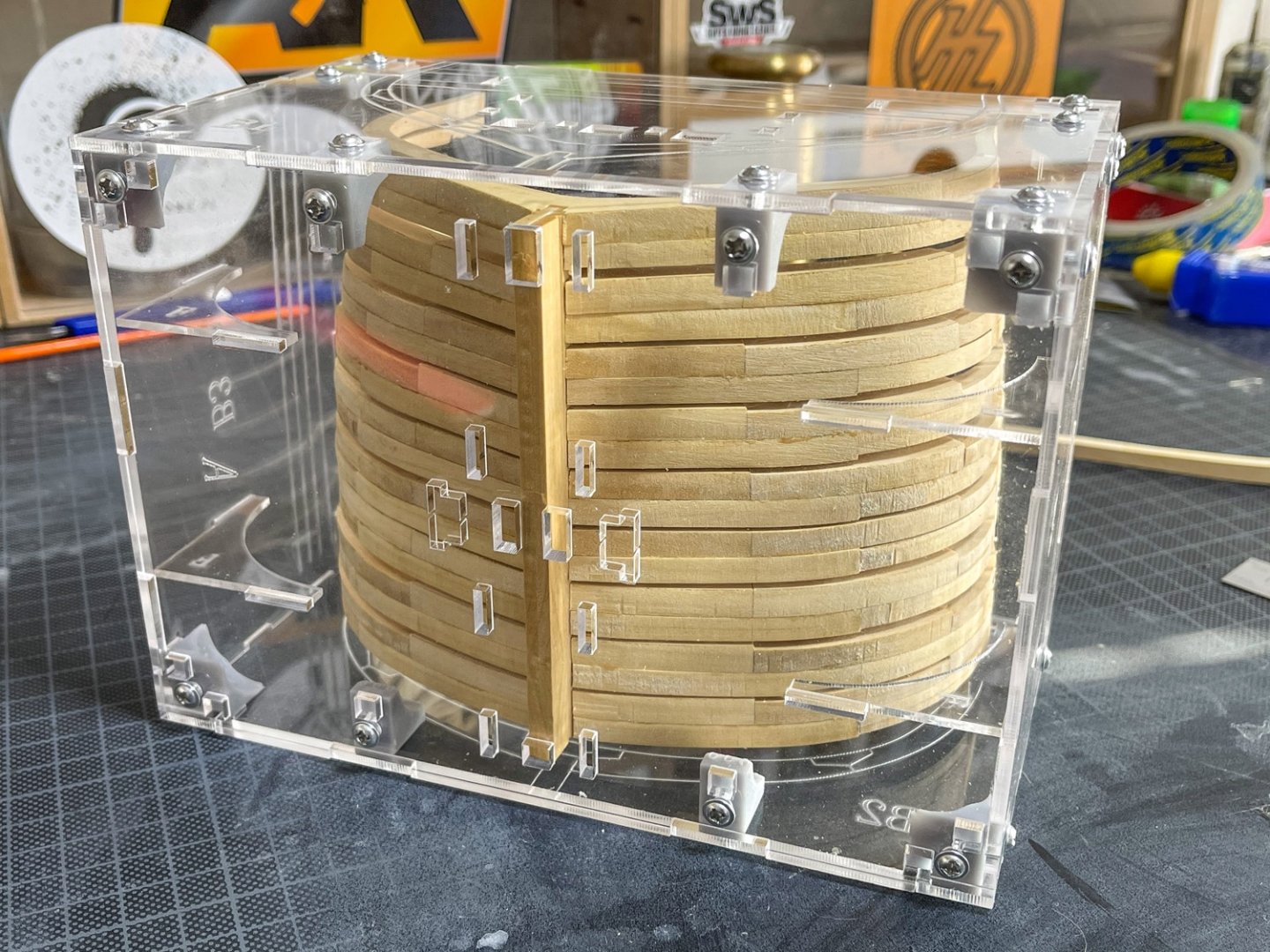
I built up each individual frame with chocks, as per plan, then roughly bevelled up to the laser engraving marks on each (external and internal bevel). Each A and B was then glued together and sat into jig on keel (no glue) where I'm currently sanding the interior to smooth it out more. When that's done, I'll remove the double frames and give a proper sanded internal finish and fit 'nails' to the chocks. Then I'll add poly to the side faces of each, then glue to keel and start to fit out the interior. Well...that's my plan. I've never done a POF before.
-
kit review 1:48 HMS Granado ‘Cross Section’
James H replied to James H's topic in REVIEWS: Model kits
A QUICK CALL FOR THOSE WHO ASKED FOR THE GROUP PROJECT: Please can you post at least the start of a build log on our group project area? It's lonely out in space! https://modelshipworld.com/forum/168-build-logs-for-the-caf-granado-cross-mid-section/ -
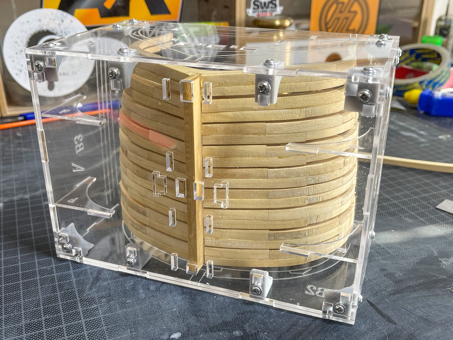
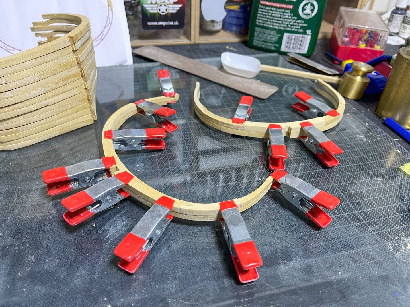
Another short update. With both halves of the double frames assembled and joining faces cleaned up, an internal bevel was applied using the laser guideline as an indicator. The chocks were also stepped where they lay across a thinner futtock. I only used the bevel lines as a rough guide as the laser markings seemed to be in a slightly different position on some opposite frame parts. I cracked the Titebond out and carefully aligned the double frame parts, using the plastic spacers on the frames that required them. The slight traces of the bevel line remnants were also used as a guide to help align the double frames. When all double frames were dry, they were given a test fit into the jig. As I found they needed only minor fettling, I left them in so I could use the alignment to fair the inside frames with some sandpaper and smooth things more.


- 16 replies
-
- 18
-

-
Any pictures which remain at the end of a post are ones that were uploaded and not inserted elsewhere in the post. The system just dumps them at the end instead of not using them.
-
When you upload the photos, you still need to click in your post where you want a specific photo(s), then click on the uploaded image to insert into that position.
-
THAT is superb! What a great shape and clean finish.
-
Ok, just bought a tin of Rustins poly satin which will be with me on Saturday. Looking forward to giving this a try. 👍
-
Thanks for that. So you use satin? Have you a photo of exactly what you are using? Sounds silly, but I presume you literally just wipe a thin layer over the timber? I have a bottle of this. I presume it's suitable? https://smile.amazon.co.uk/Bartoline-19925070-750ml-Spirit-White/dp/B005EFUSQW/ref=sr_1_2?dchild=1&keywords=bartoline+white+spirit&qid=1614275375&s=diy&sr=1-2 I'll do a search for that topic.
-
Can anyone help with an alternative to Minwax Wipe-on poly, in the UK? There is some Minwax on Amazon, but I'm loathe to spending around £30 for a tin of something that I don't know is as good. I'm using this for the Granado section and still need to be able to glue once applied. I definitely need 'tried and tested' 🤣 Jim
-
Nobody said you were excluded. That's your own extrapolation. Maybe the reason you also didn't post here was you couldn't log in for months after successive failed login attempts and lockouts. If you'd contacted via the form, I could've fixed that immediately for you, but never mind. Posting on SOS does not preclude your ability to post here. We have lots of dual members, and no one even suggested you were building/bought a Chinese kit. Where did that come from? Someone only mentioned that SOS is a harbour for those who want to build them. I do agree about the doorknob on the backside comment. That was uncalled for. If you ever want to post any further work here, then feel free. No one is stopping you. You might also get more interaction on your own log if you venture outside of it and comment on others too. Just sayin'.
-
Tonight I managed to finish all the facing surfaces of the 9 double frames, so it's onto internal bevel next before gluing the doubles together and fitting to the keel.

- 16 replies
-
- 14
-
-
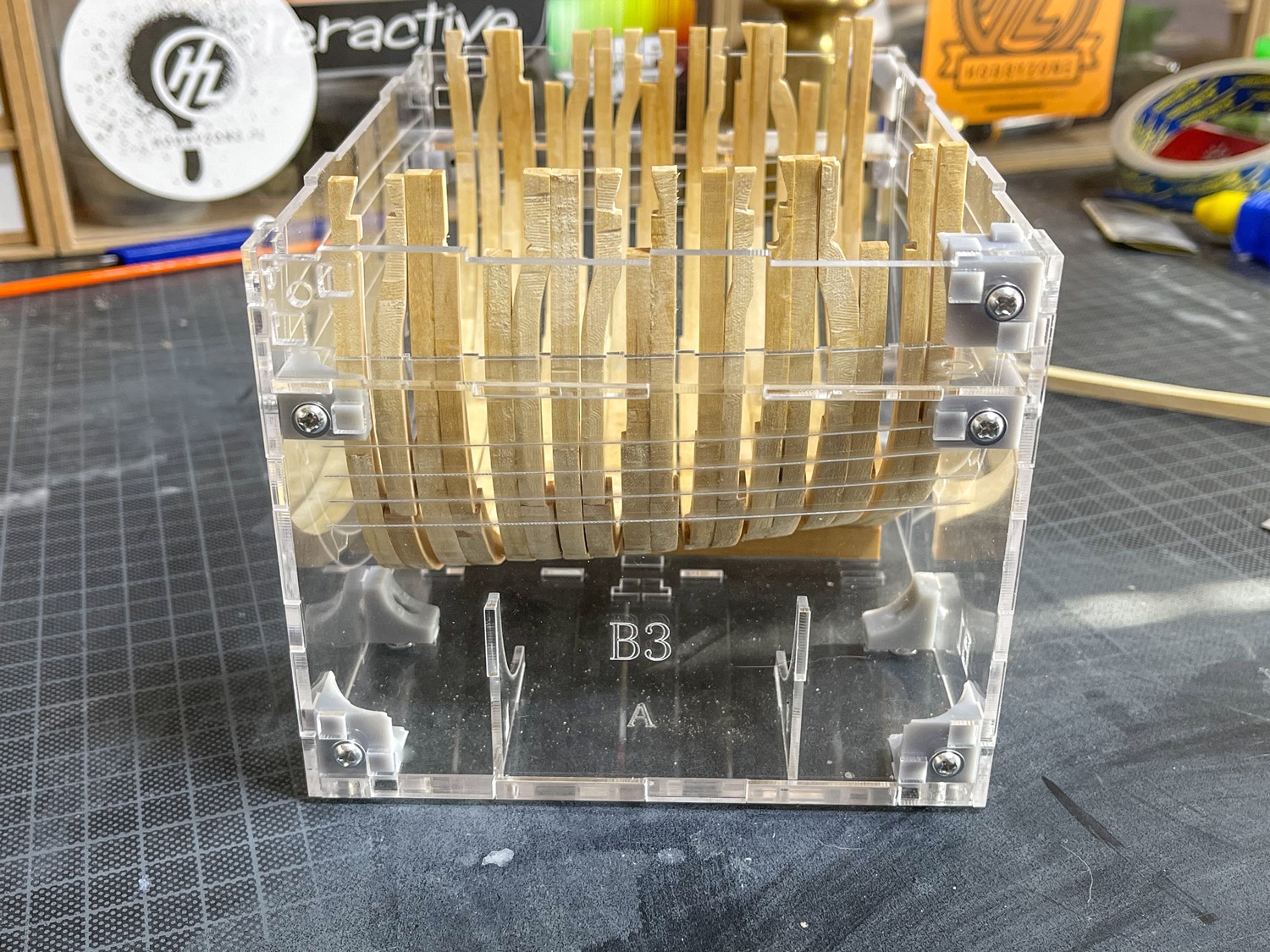
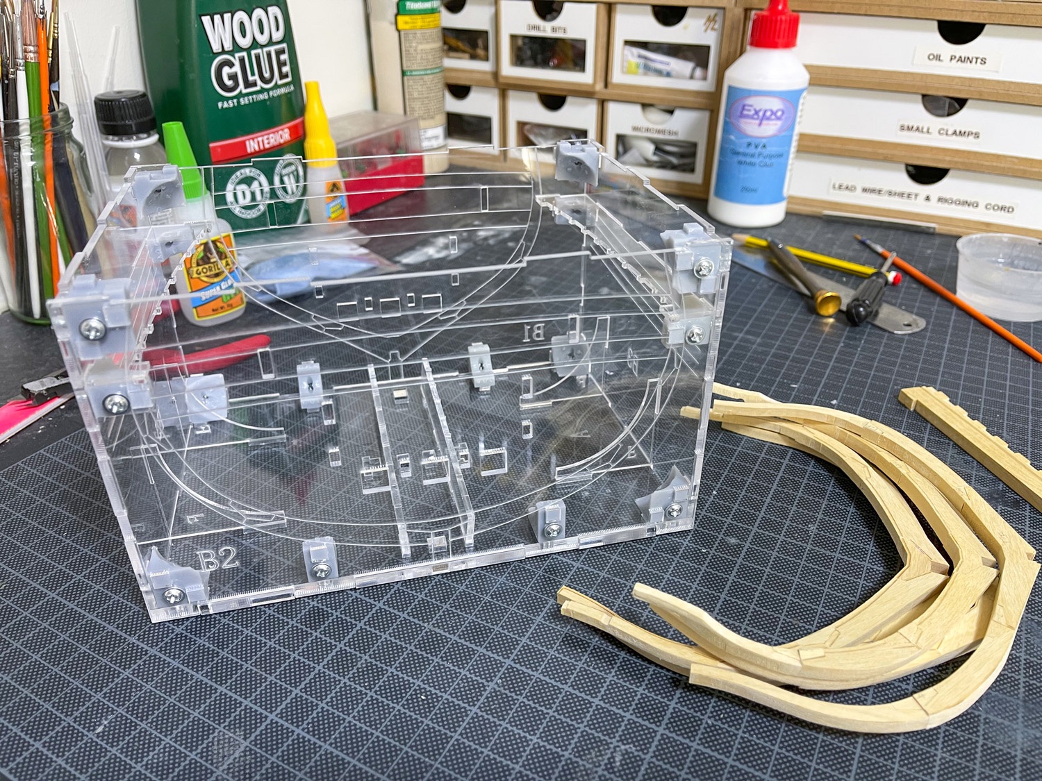
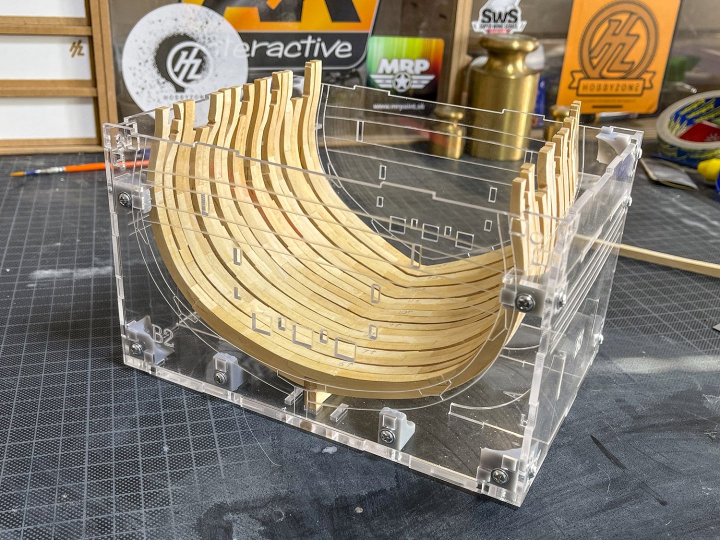
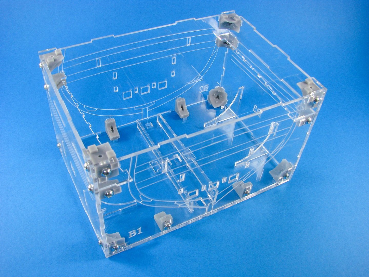
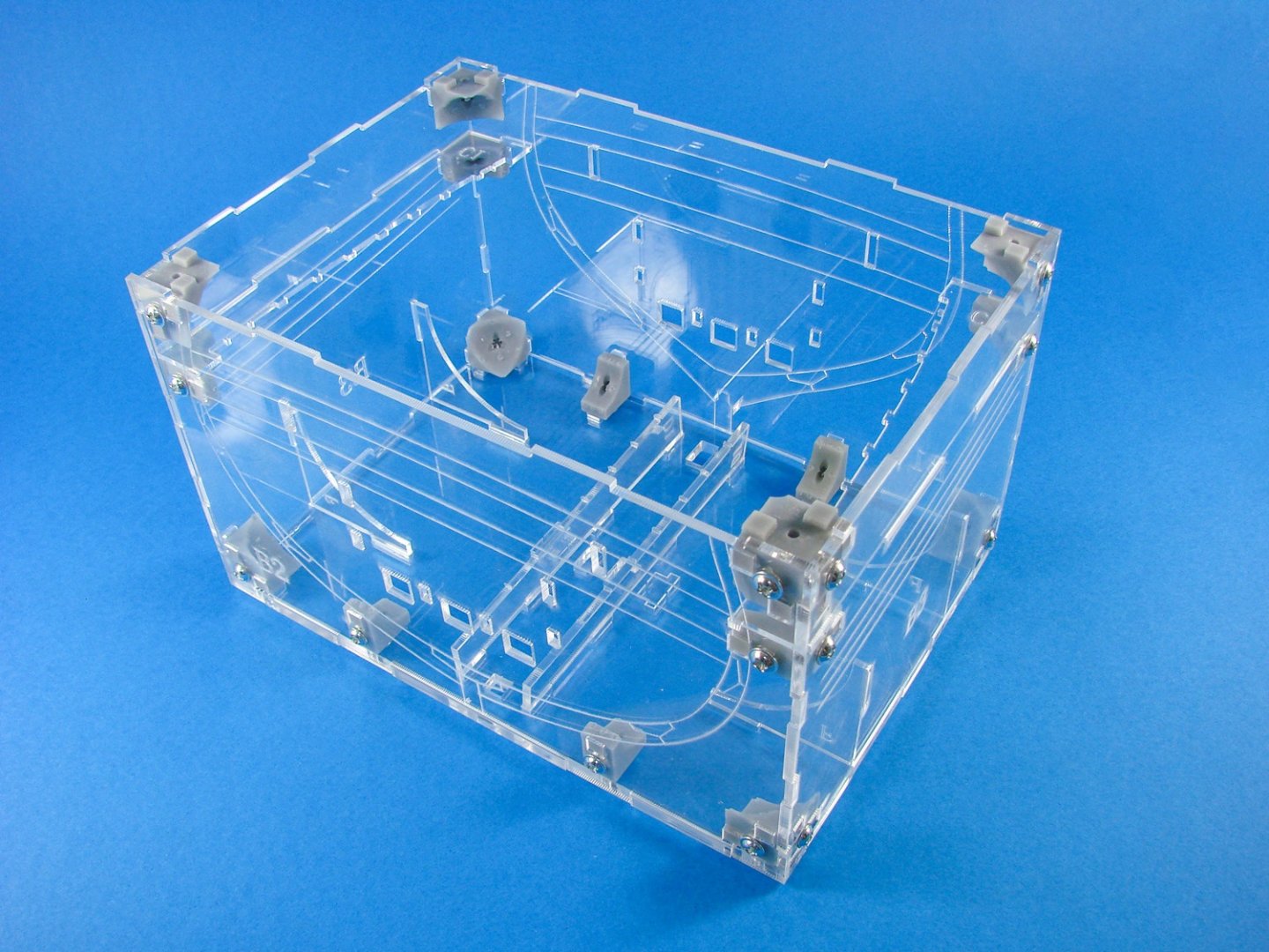
I'm still working away on the frames and have a little more to do on them before I can look at fitting to the keel. In the meantime, I built the acrylic jig. I'm aware that some panels may need to be removed to fit frames in etc. The jig will only really built one way because of length and positions of slots, so don't fear getting anything wrong on this. One tip I do have is to slightly open up the holes in the plastic fixing blocks. I think I used a 3mm drill, but it's simple enough to fathom. Another reason for this is that the blocks seem to be 3D printed (not regular plastic/resin) and they are slightly brittle. If you don't open them up, they are liable to break. Even opening them up, some still fractured at the surface when fully tightened. Just be careful.
- 16 replies
-
- 14
-
-
I've been told that there has been talk with UMM and SprueBrothers, but nothing has come of this. If anyone is interested in being a US distributor, or knows of someone who is, please let me know.
-
No worries. I'm still waiting from Artscale regarding my query on American distribution.
-
I don't want to seem disrespectful guys, but articles would be no good if everyone just posted links to alternative items. This review focuses on the merits/demerits of the Artscale razor saw. Can we focus on that please? If we just have a free for all, then we are less likely to see companies want to have their releases checked over here.
-
Glad to see you're keeping busy, but more so to see you back here. Looking forward to your update on the vaporetto.
-
That's actually the one I currently use. I do find them very easy to twist and buckle. Screwed a few up over the years with that. They also seem to blunt fairly quickly when just cutting resin etc.
-
I have asked about this for you. Maybe there is an answer. ...and there will be new profile blades released in the near future too. I'll add those when they arrive. I know what you mean about their website. They have some really wonderful stuff. You can also pick up your fix of coffee while there too 😜
-
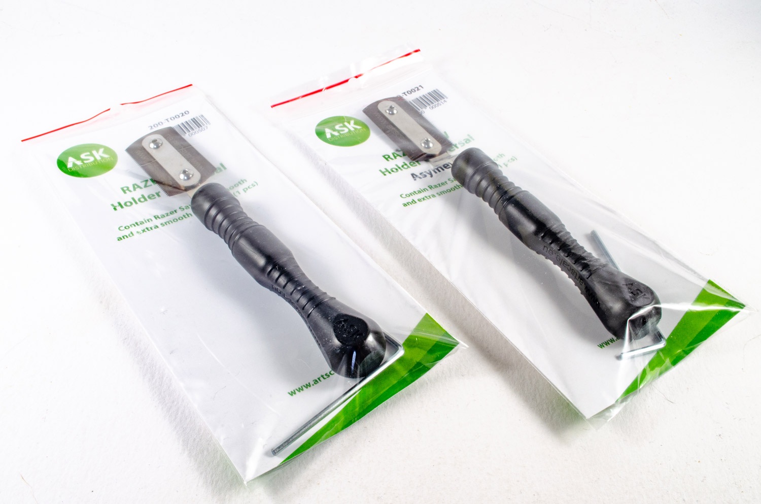
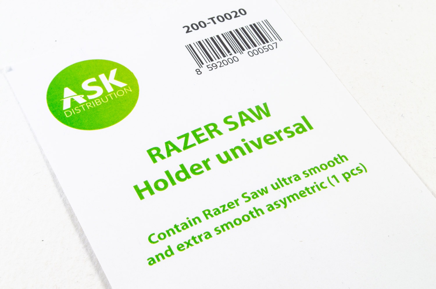
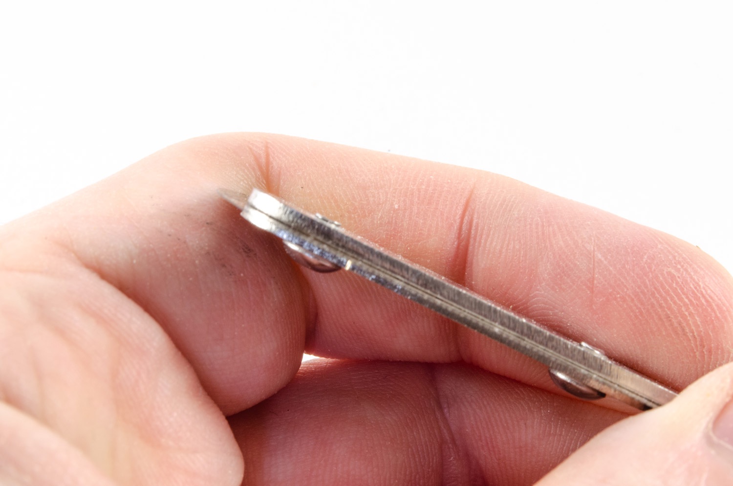
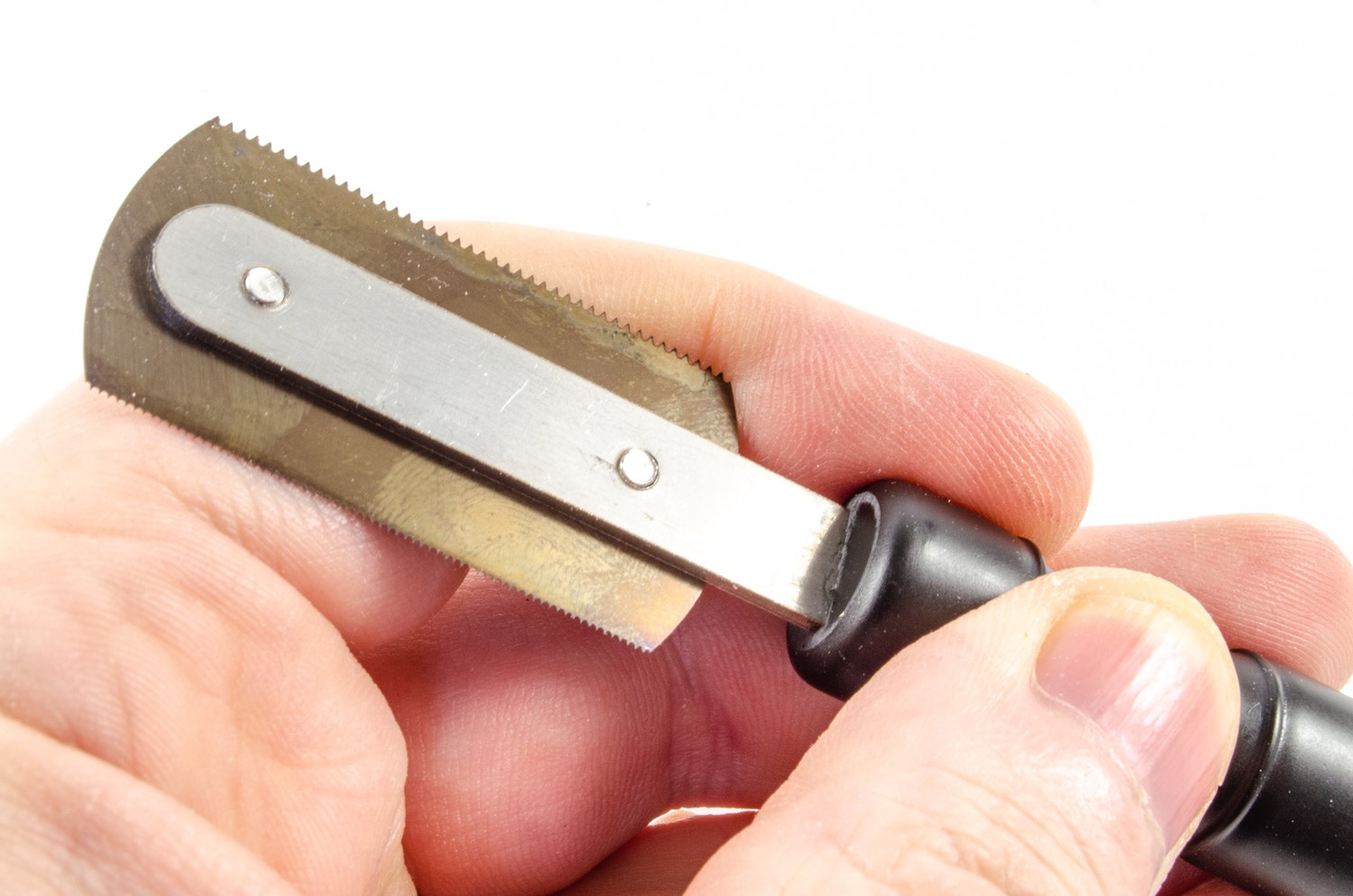
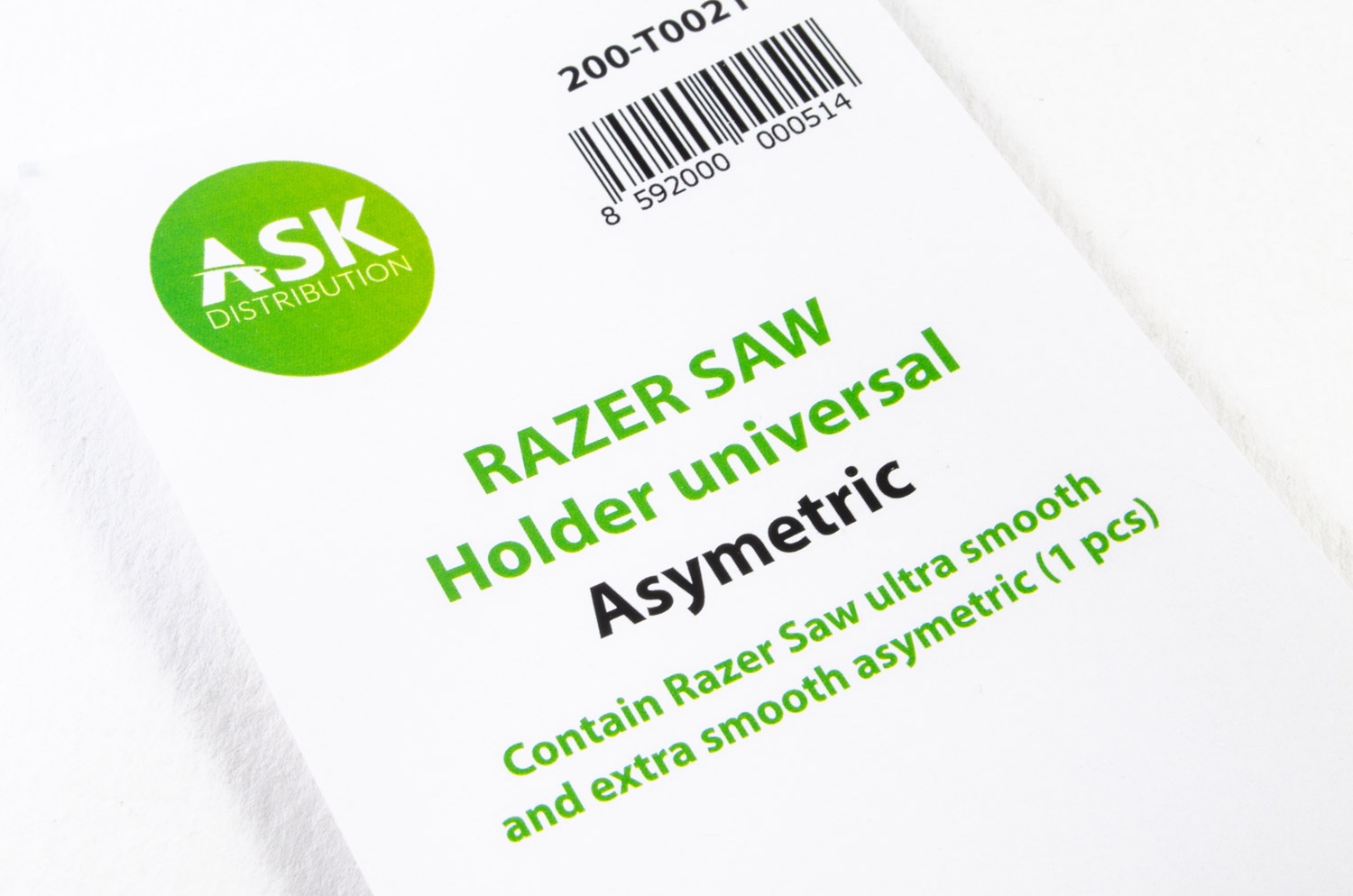
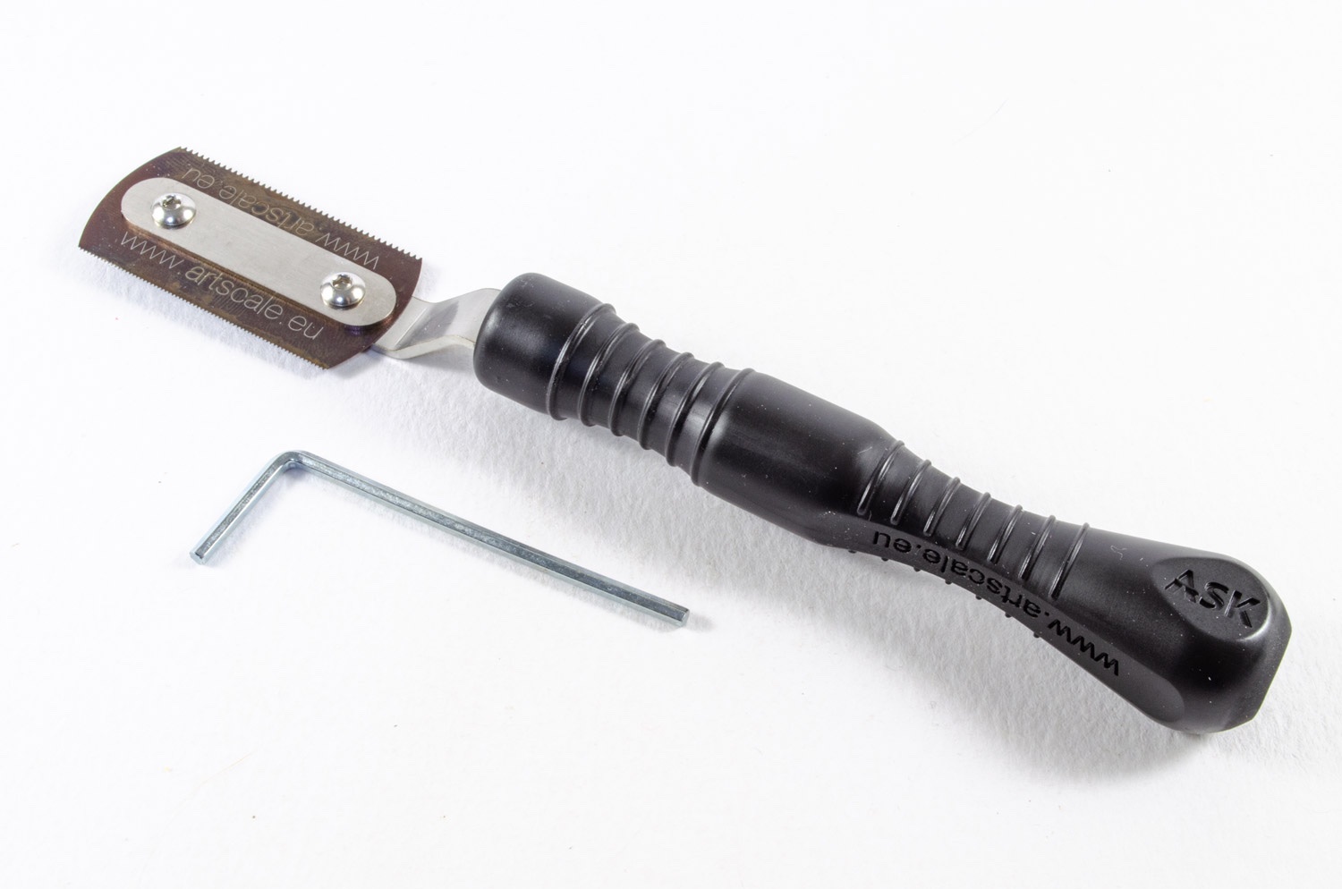
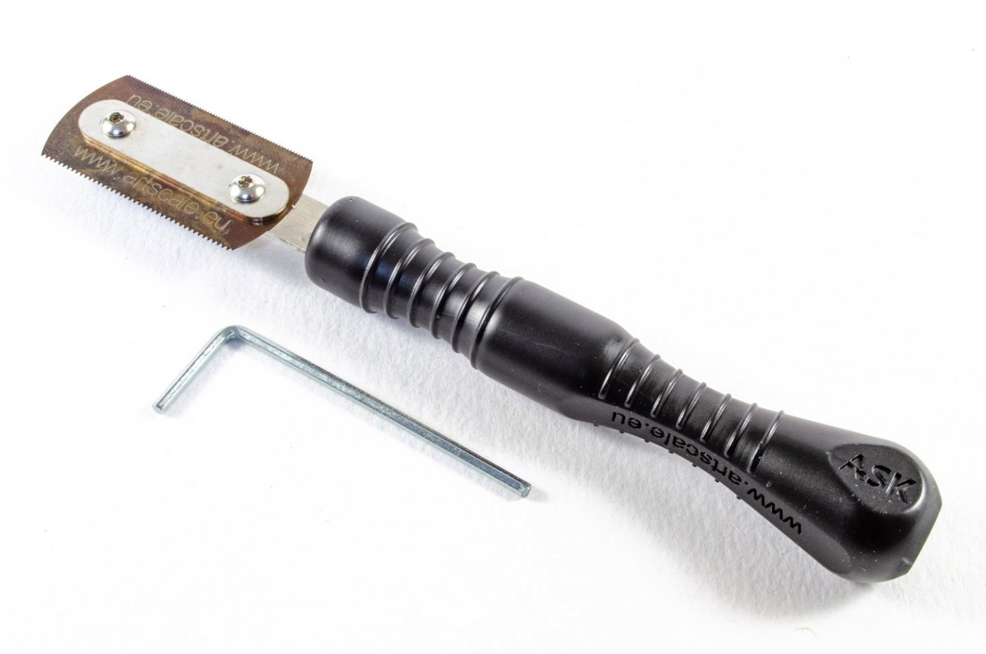
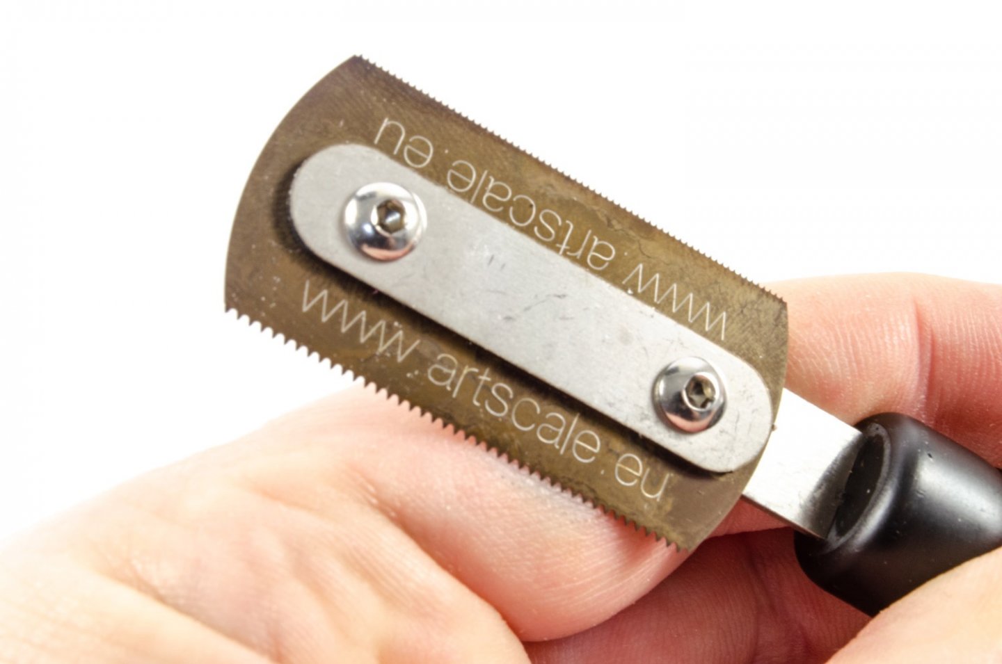
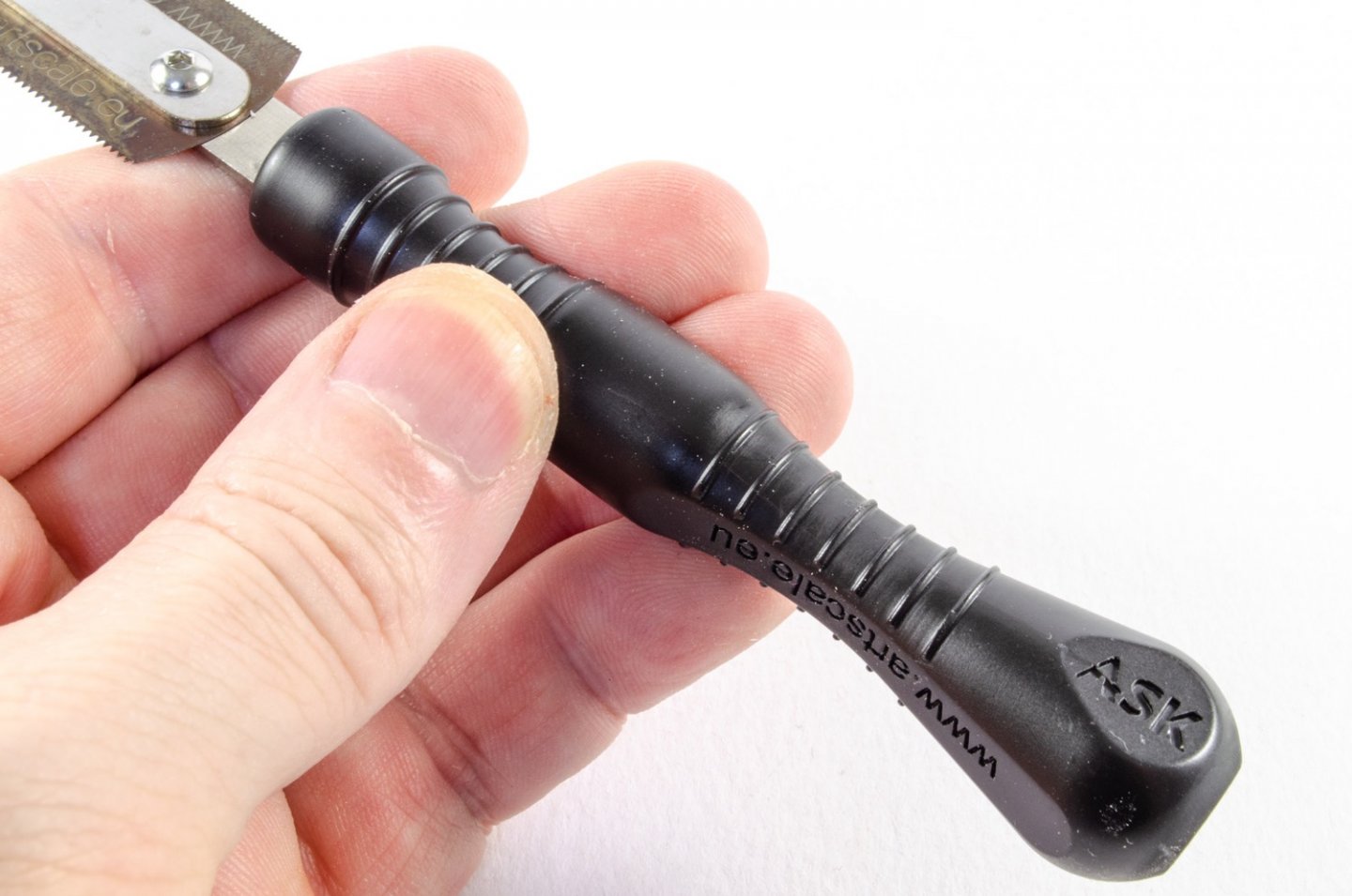
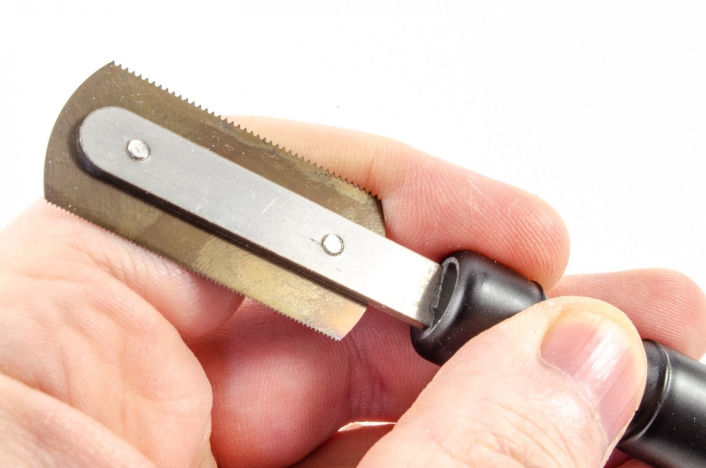
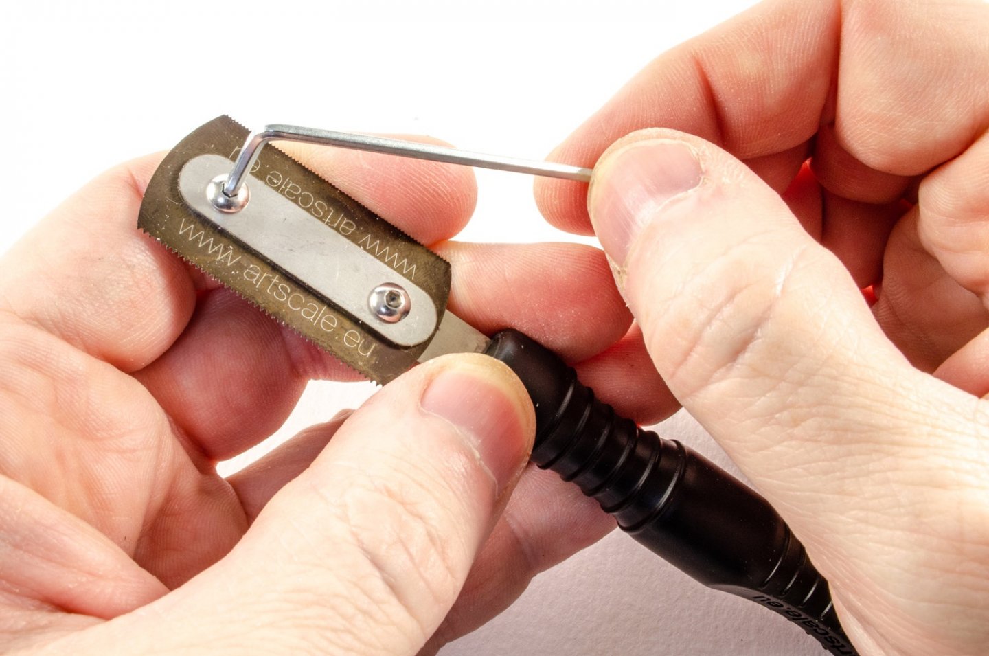
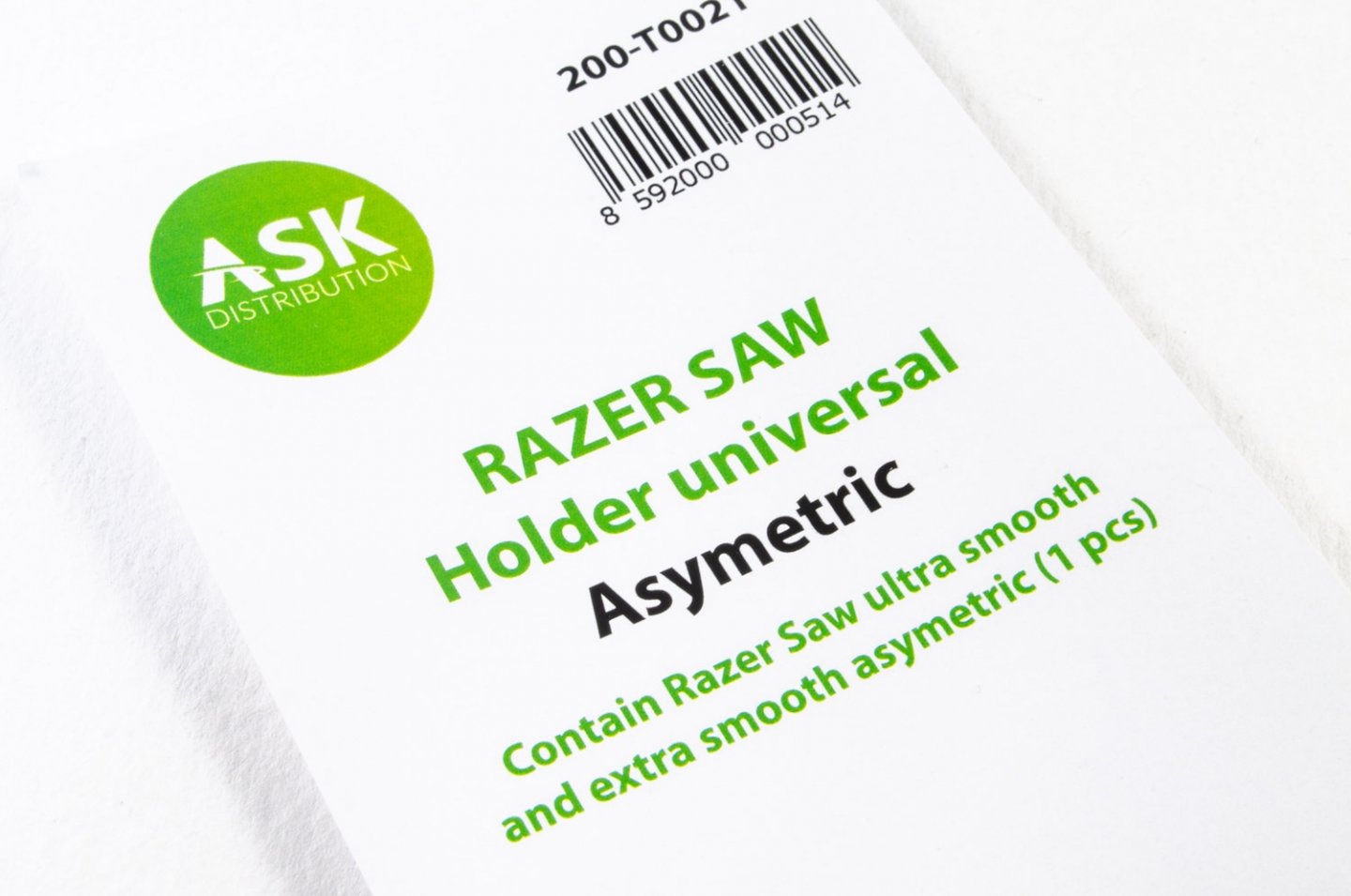
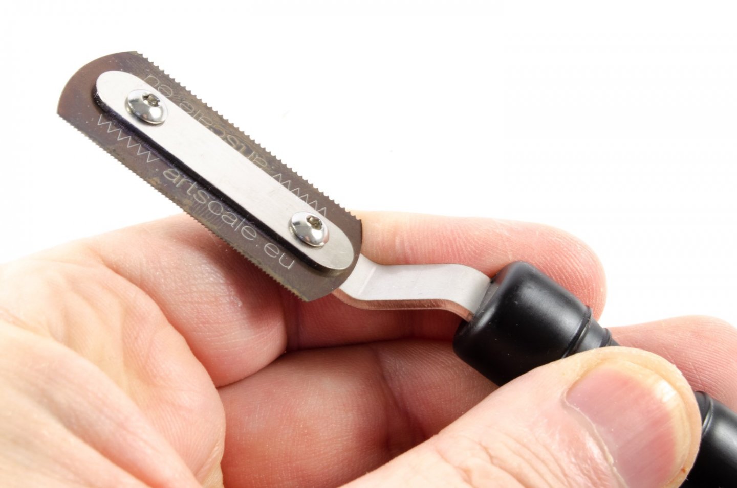
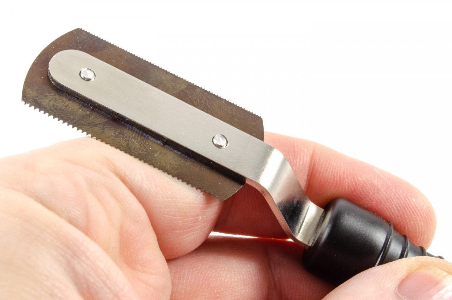
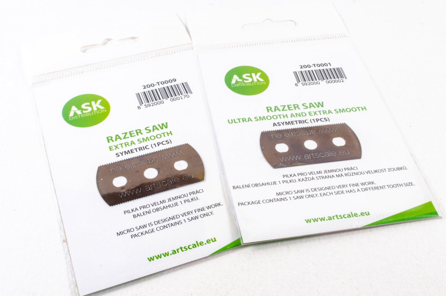
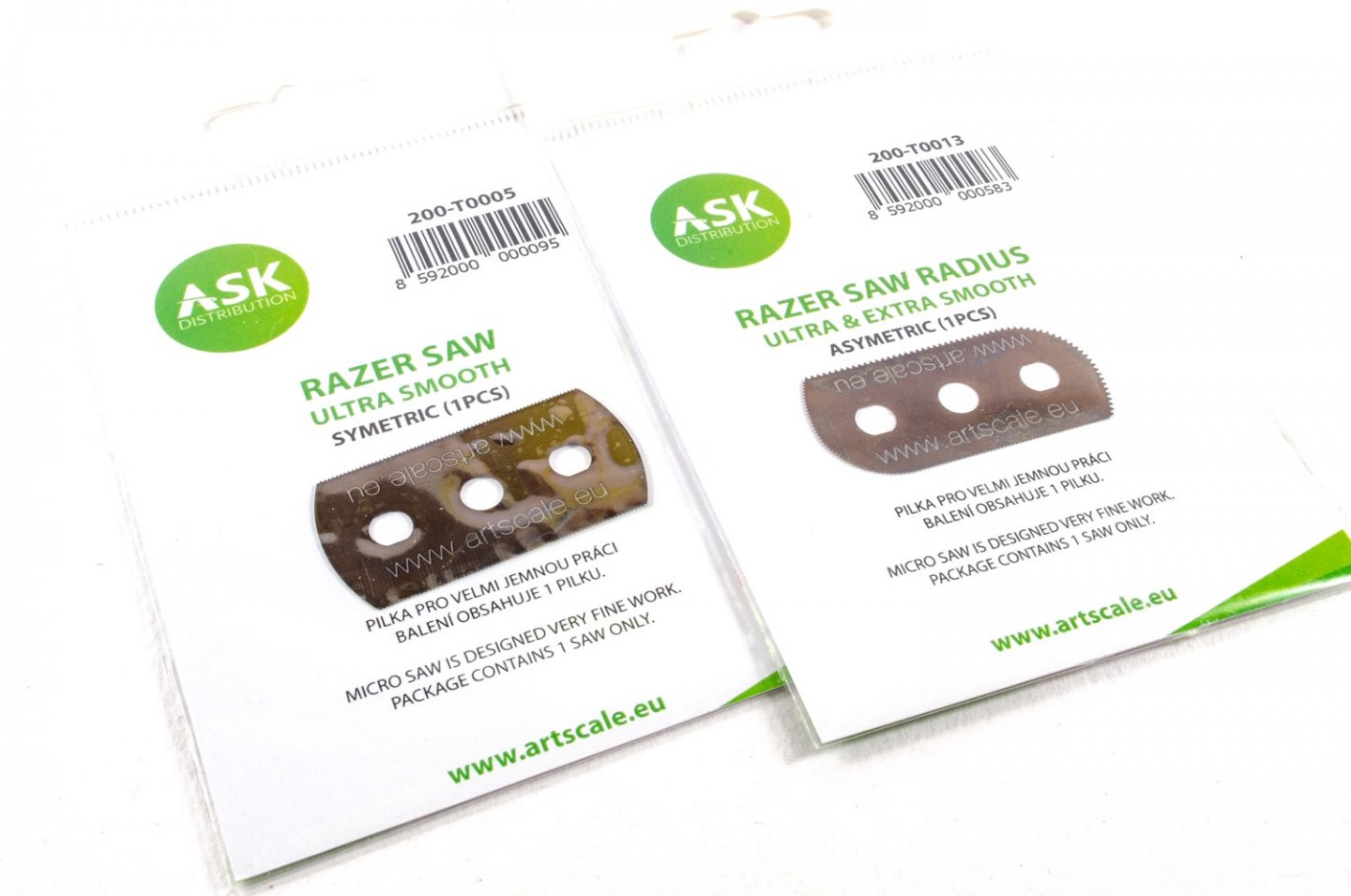
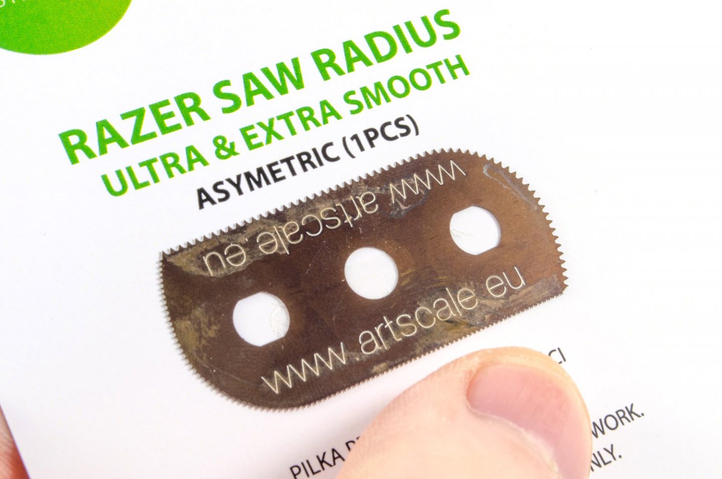
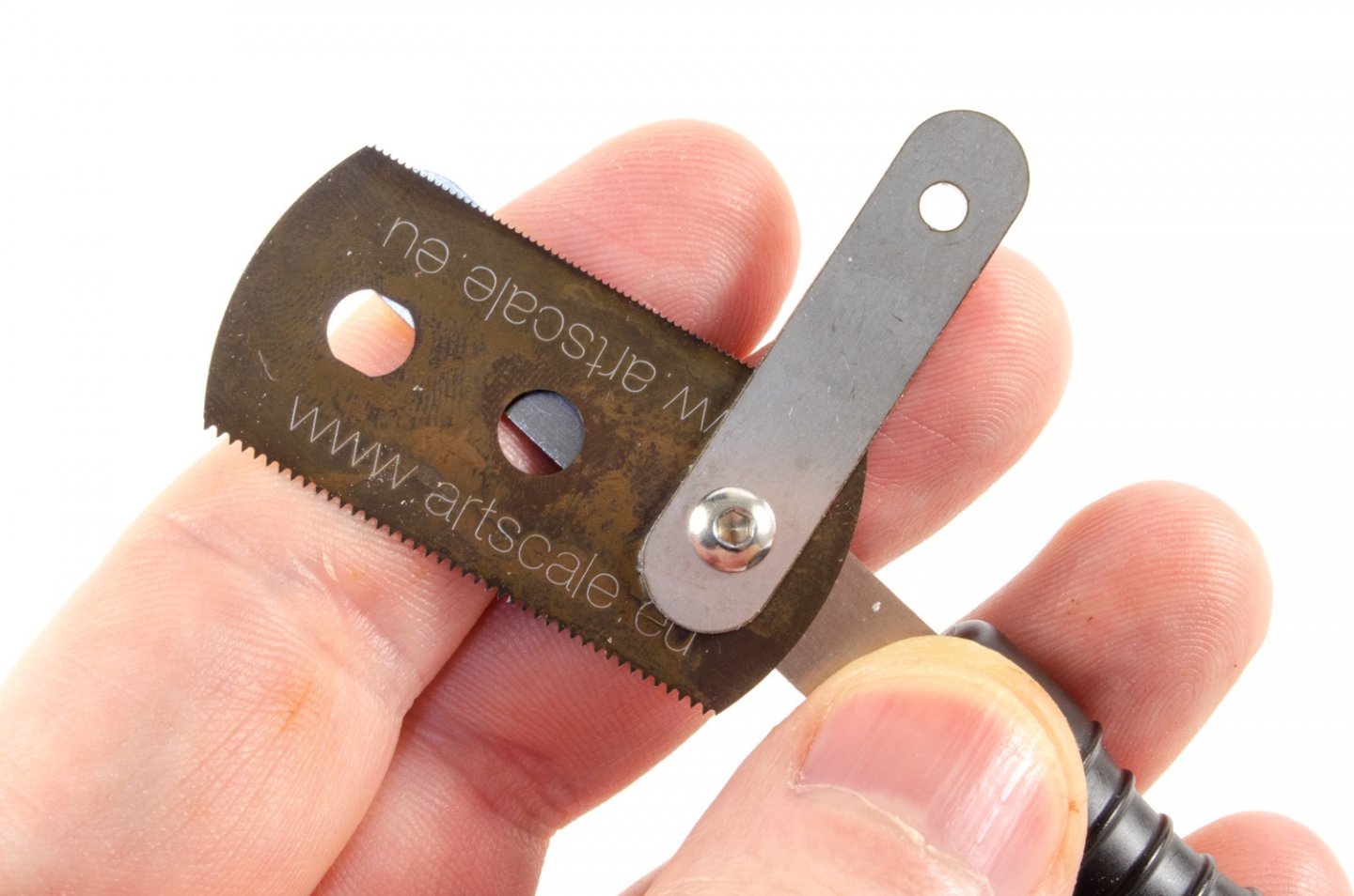
ASK Razor Saw holders (straight and asymmetric) Artscale See article for codes, links and prices I’m a sucker for nice tools, and one that is used most frequently in my arsenal is my trusty razor saw. I use this for all sorts of materials, including plastic, resin and now also wood. You sort of instinctively know when you need to get it from the tool rack, for those jobs where a knife would be too challenging, or cutters would be too destructive. They are great for making fine and precise cuts that remove an absolute bare minimum of material, unlike a regular saw. I also use mine to gently re-scribe any shallow and fine panel lines on plastic. Razor saws can be particularly good for that task and they don’t leave ridges of material behind like many regular scribers. Artscale recently sent me their two new razor saw releases to see what I thought, and it provided a useful comparison to the brand I currently use. That latter brand is actually very good and has blades and mount which are made from photo-etch stainless steel. For a handle, the tool is mounted in a regular X-Acto style handle. Two slightly different razor saws have been sent for evaluation. These are: Razor saw – Universal (200-T0020), €14,95 Razor saw – Asymmetric (200-T0021), €16.95 The ‘Universal’ style has a straight blade mounting system, whilst the ‘Asymmetric’ has an offset blade mount which is very useful for those awkward cuts, or for those where you want maximum visibility of the material being cut, without your own hand getting in the way. The razor saws sent for evaluation are complete tools and need no third-party handle. Black ABS plastic is used for the handles on these, and the whole tool is nicely balanced in the hand as well as being comfortable when gripped. The blades are also more rigid than the brand I currently use whilst looking every bit as thin…exactly the remit of a razor saw. In fact, these blades are 0.12mm thick). Both of the supplied saws are fitted with the same blade (ultra-smooth and extra smooth asymmetric – two different tooth/pitch sizes). That single blade is also that is provided in each of the saw packs, with replacements and different types being available both individually or in multi-packs. Both saws have a beautifully designed system of blade change which also doubles up to provide reinforcement to the blade itself. It’s also a single-tool system for changing the blade too, with a hex-head key provided. There are two hex screws which drop through a reinforcement plate and the blade, before screwing into a threaded reinforcement plate on the rear. This is handy as my current brand requires a small wrench and a screwdriver to change the blade. The blade mounting holes are also central to the blade, meaning each cutting edge can be used without having to reposition the blade in the handle. In use, the blade stays nicely straight without any awkward flexing, and it’s super sharp too. There is also a certain amount of freedom in positioning the blade in the tool, in case you want to set it to a certain depth of cut. Razor saw blades Artscale also included packets of the blades they currently supply for use with their new razor saw. I have the individual packets, although you can buy these in multiples on their website. Ultra-Smooth (symmetric) - €1,90 Ultra & Extra Smooth Radius (asymmetric) - €2,60 Extra Smooth (symmetric) - €1,90 Ultra & Extra Smooth - €1,90 Conclusion I’ve been after something to replace my current razor saw as the blades in that are way too easy to bend and buckle without the utmost care. Artscale’s new tools seem to answer that need perfectly, and the blade options are very useful too, depending on application. These new razor saws and very nicely made and feel right in the hand. They are also super sharp too! If you are in the market for a new razor saw, whether a replacement or your first, these would be a very good option to consider. Here’s the tool data sheet with more technical information for you. ASK-Handle-saw-pdf.pdf Sincere thanks to Artscale for sending these tools out for evaluation on MSW. To buy directly, click the links in the article.


-
I did only say 'feel' like one 😁
-
I had no idea about the differences between a cutter, pinnace, launch or barge before I built these. Now, I feel like an expert 😆
-
He's told me to tell you he has been without internet/phone for a couple of days, and his business relies on it of course. In his area, even the mobile telephone signal is really poor too. All should be sorted early next week.