


thibaultron
-
Posts
2,637 -
Joined
-
Last visited
Content Type
Profiles
Forums
Gallery
Events
Posts posted by thibaultron
-
-
Just about any type of the self-healing mats will work, In the US they are available from craft stores, and Walmart. Generally they are in the sewing section. Hobby stores should also carry them. My present one is 12X18". I also have a thick plate glass ex-shelf, that I use. This tends to dull my blades quicker than the plastic mats. It does make a good flat surface for assembling models though. The glass plate is also nice, in that you can slip a drawing under it, while modeling for reference. No worry about damaging the drawing, or photo, while also making sure it stays in place.
-
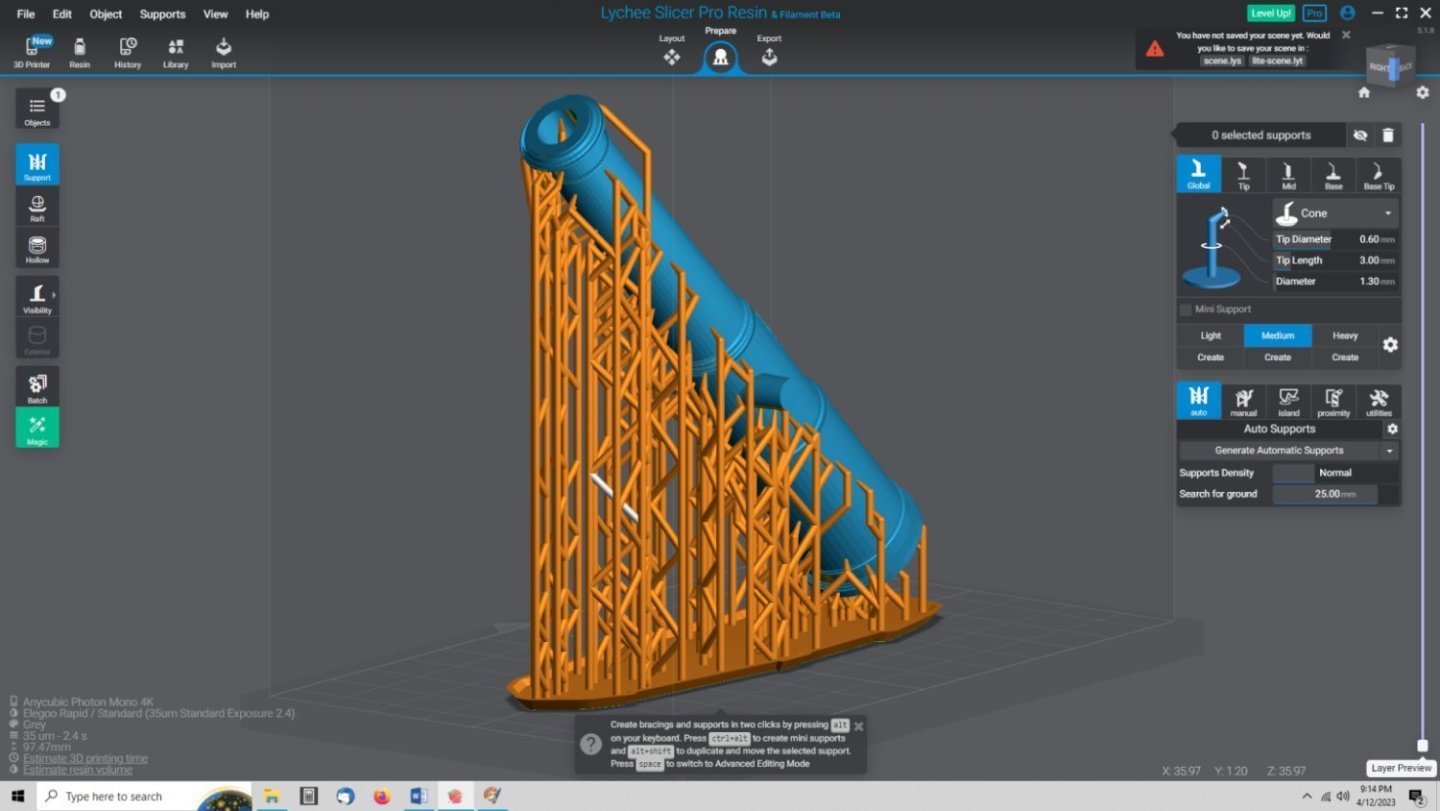
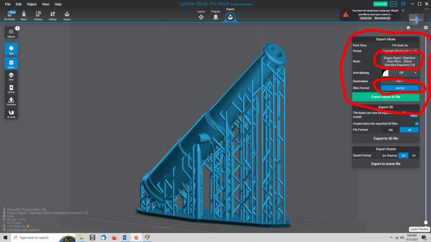
Earlier in this thread I detailed my setup for the supports. I orient the cannons at 45 degrees (gives best detail), with the barrels pointed with the muzzle directed away from the build plate. This allows the resin to sort of drain away from the print, during printing. This also gives a better base attachment to the solid breach area, rather than the thinner hollow muzzle.
I use Lychee for my slicer program. After angling the barrel, I raise the part up 5mm away from the plate. I use the Raft Form baseplate. The angled walls of the raft allow for easier prying of the parts off the bedplate. I see that you did use the raft in your prints. You don’t state the scale, so that makes this last a little difficult. From about 1/24th to around 1/64th, I use the automatic support feature with medium supports. After that finishes, I go back and manually place two heavy supports under each of the two trunnions (one at the trunnion to barrel area, and one at the tip). I then see if there are any more yellow areas shown, and may add more medium supports to those areas. For smaller scales, I use light supports, with medium ones at the trunnions.
This graphic shows a 1_24th scale 32 Pounder cannon, after the medium supports have been auto-generated.
In this graphic, I have added one of the heavy supports to a trunnion tip.

I print with a layer height equal to the pixel size on the printer. In my case my printer has a 35um pixel, so I used a 35um layer height. Yes, the 45 degree and smaller layer height take longer, but you are printing these for yourself, so just leave it overnight to print. I have an AnyCubic Mono 4K printer. If yours is different, the manufacture’s site generally has the pixel size listed somewhere in the specifications for that printer. Each layer height requires a different exposure time. So, exposure times for the standard 50um layer height will be too long for a 35um layer.
I’m going to assume that the temperature is 22C. If it is 22F, yes that is way too low. 22C or 71F should be OK, depending on the resin. Have you calibrated your exposure times? There are several YouTube tutorials on the calibration procedures.
It generally takes me a couple of test prints to get the supports right, and I always print as many as the printer will hold. I still get some misprints, so this gives more chances to get good ones you can use. Look at the failure areas and add supports at the failure points. You may also need to bump up the exposure times slightly.
3D Resin printing is more of an artform than science, to get the settings right. So, some experimentation is often needed.
I leave the cannons on the supports, if possible, while cleaning them, with small wood or plastic rod run down the barrels to force as much of the resin out of the barrels as possible, after the first cleaning, then I run another cleaning cycle.
I also use my smallest micro drill to clean out the touch hole, before the second cleaning, for larger scale prints.
Remove the supports before curing, as they will break away cleaner now, than once hardened. I let them dry overnight, before curing. This lets all the cleaning solution dry from those small interior areas. If there is still solution in when you cure, it can leak onto the outside surfaces and mar the surfaces.
If all the above still does not fully fix your problems, try raising the temperature in the printing area.
I am just a beginner, myself, in 3D printing, so I can not offer any better advice.
- Seventynet, mtaylor and scrubbyj427
-
 3
3
-
Here is an example of one of the Bogard cannons. I've drawn one in each size to check that the cyphers curve properly on the barrel. I'll draw the rest now. This is an 18 Pounder. The line on the barrel, by the cypher, is an artifact of the drawing, it would not show on a print.

- scrubbyj427 and mtaylor
-
2
-
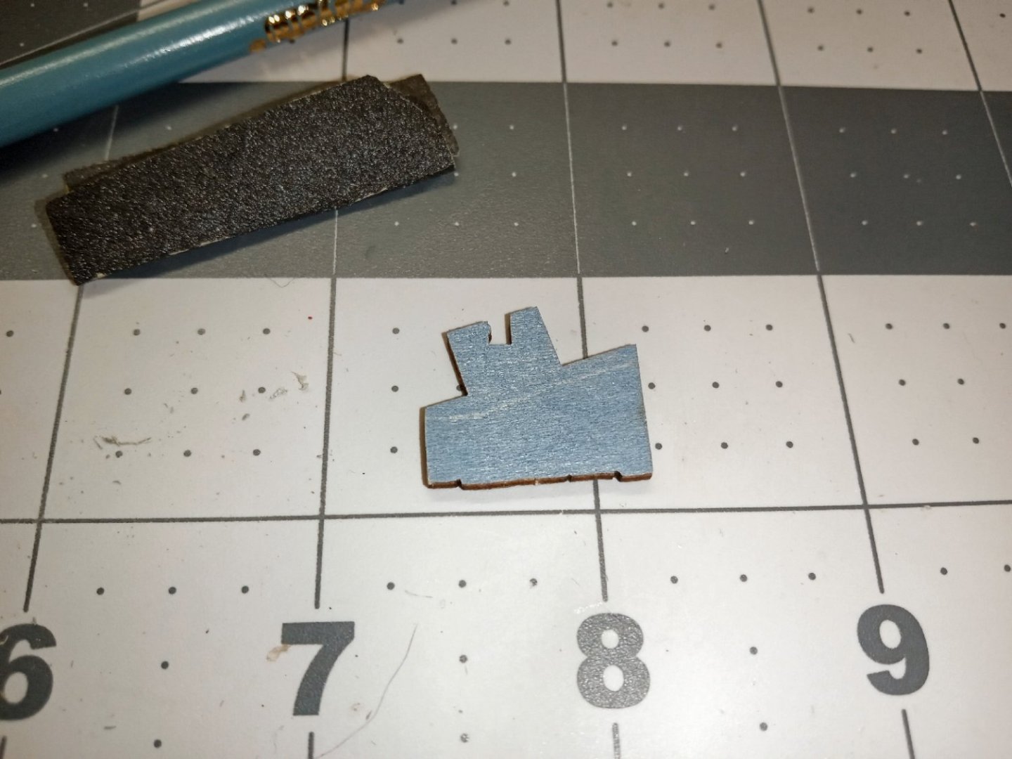
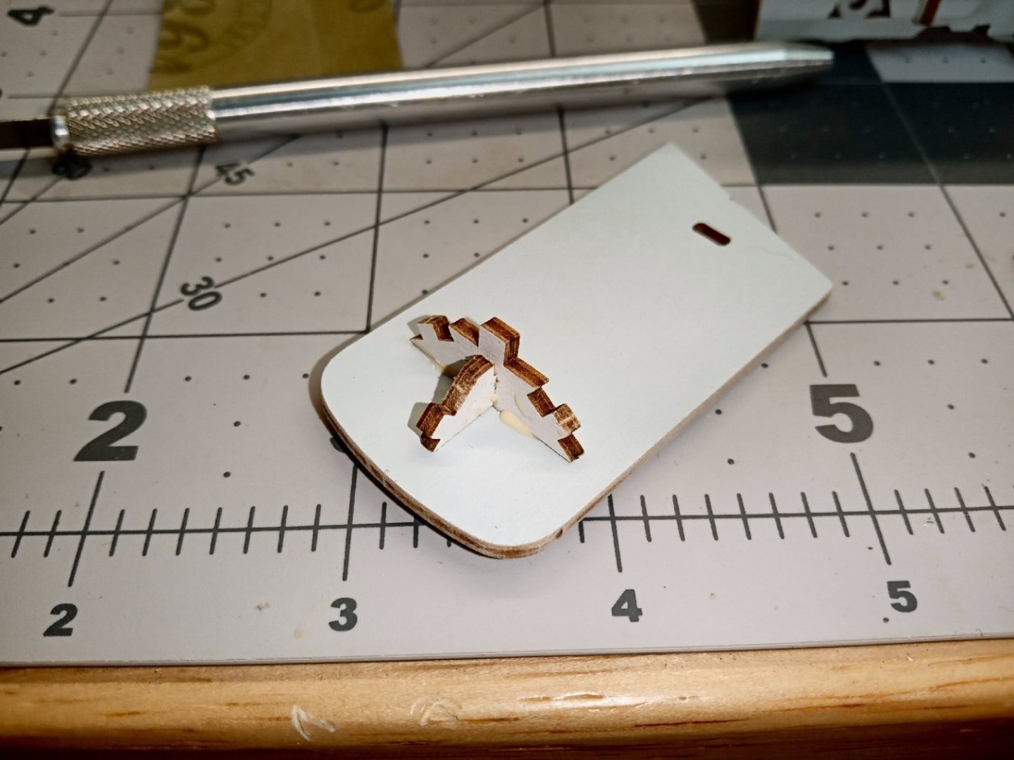
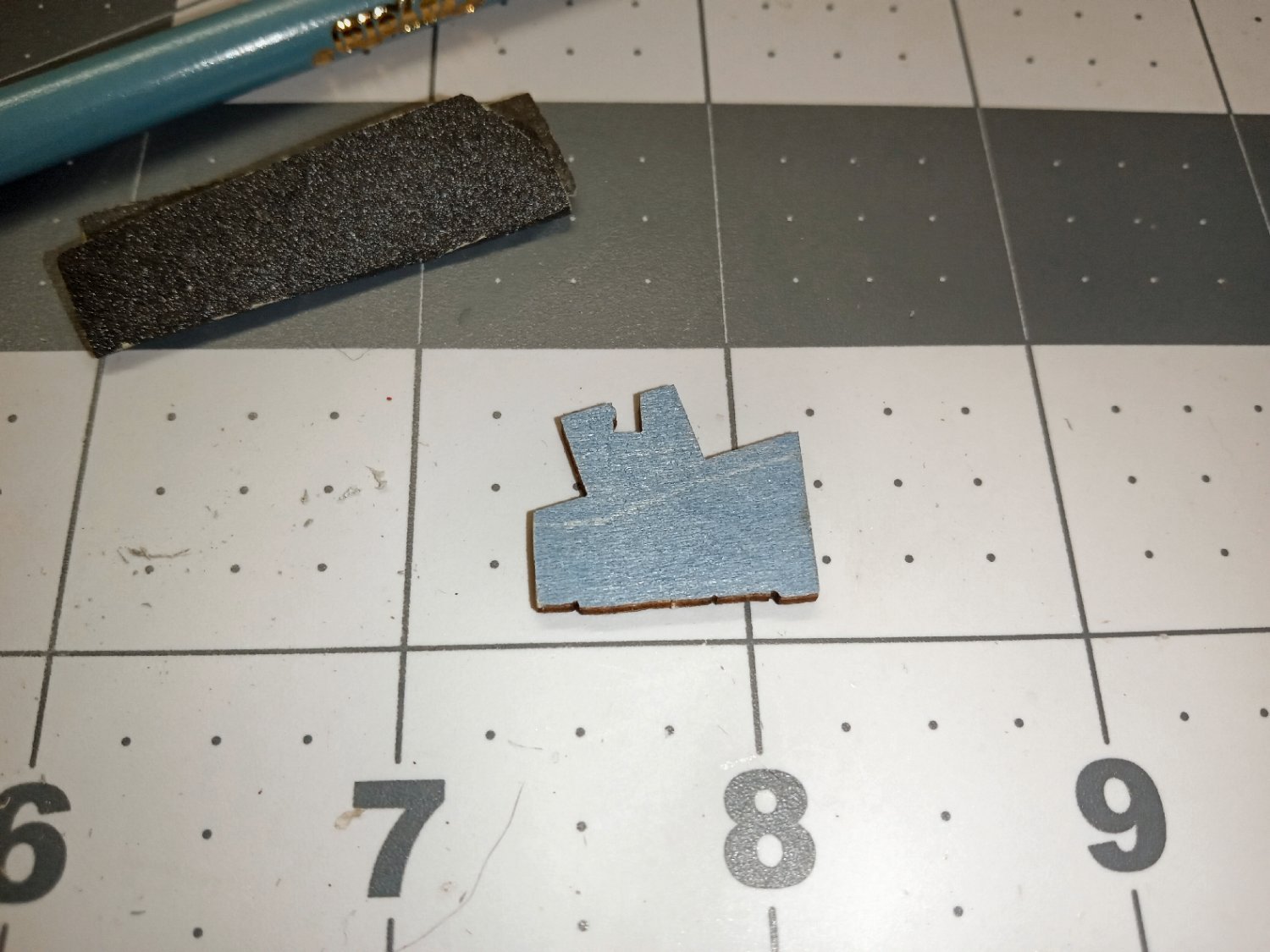
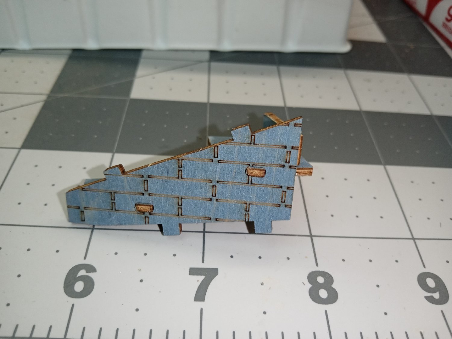
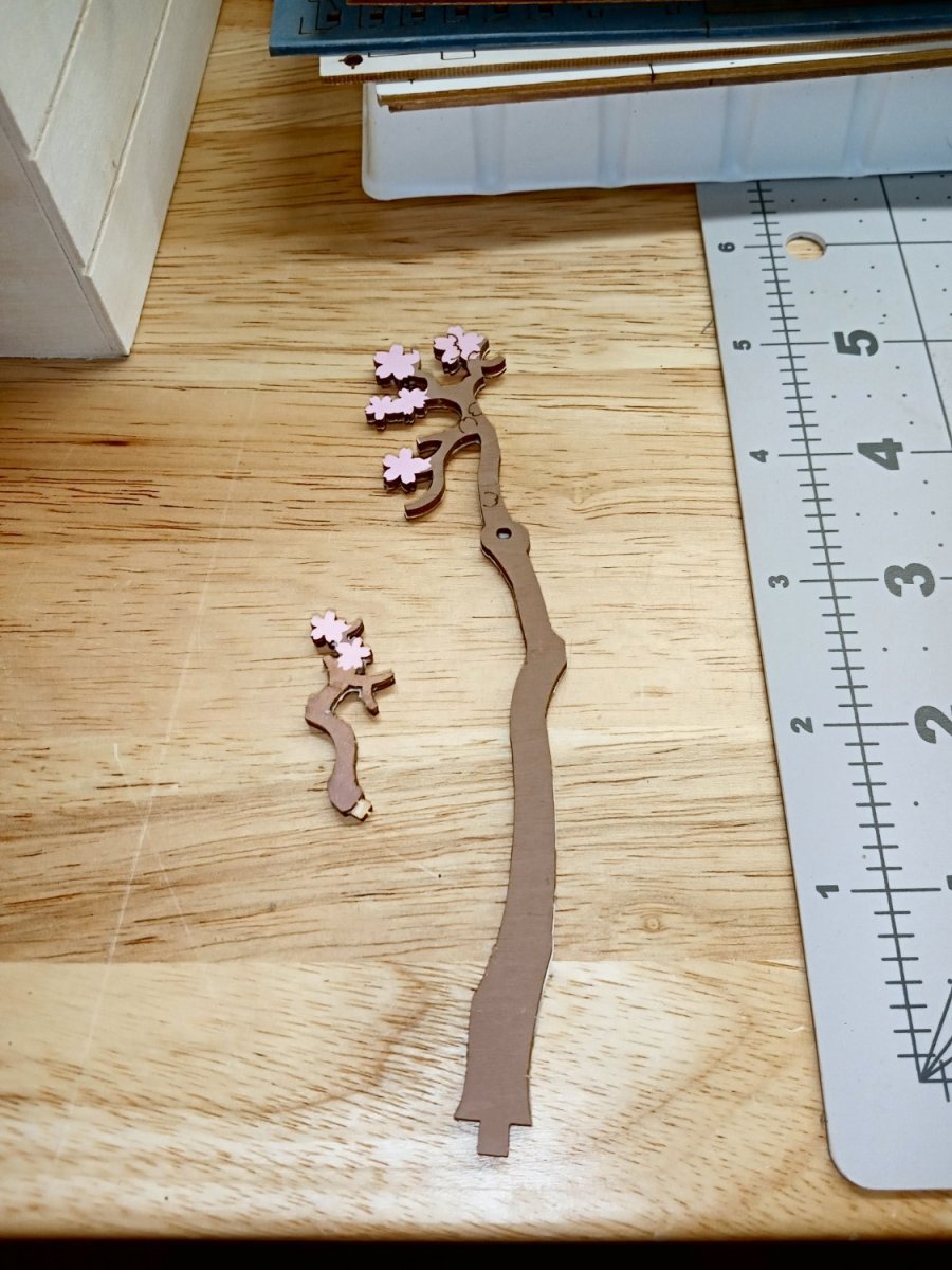
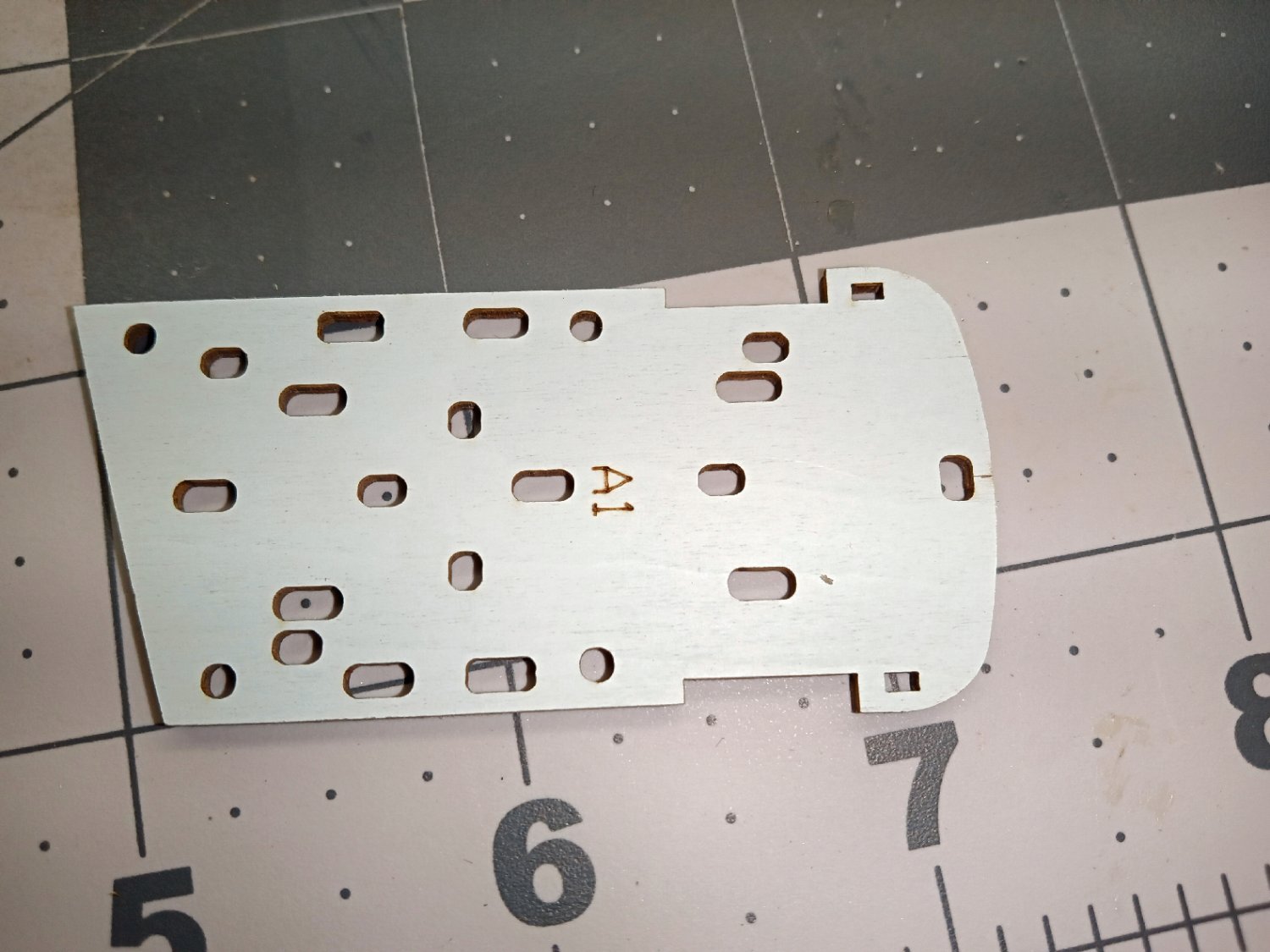
Part_016
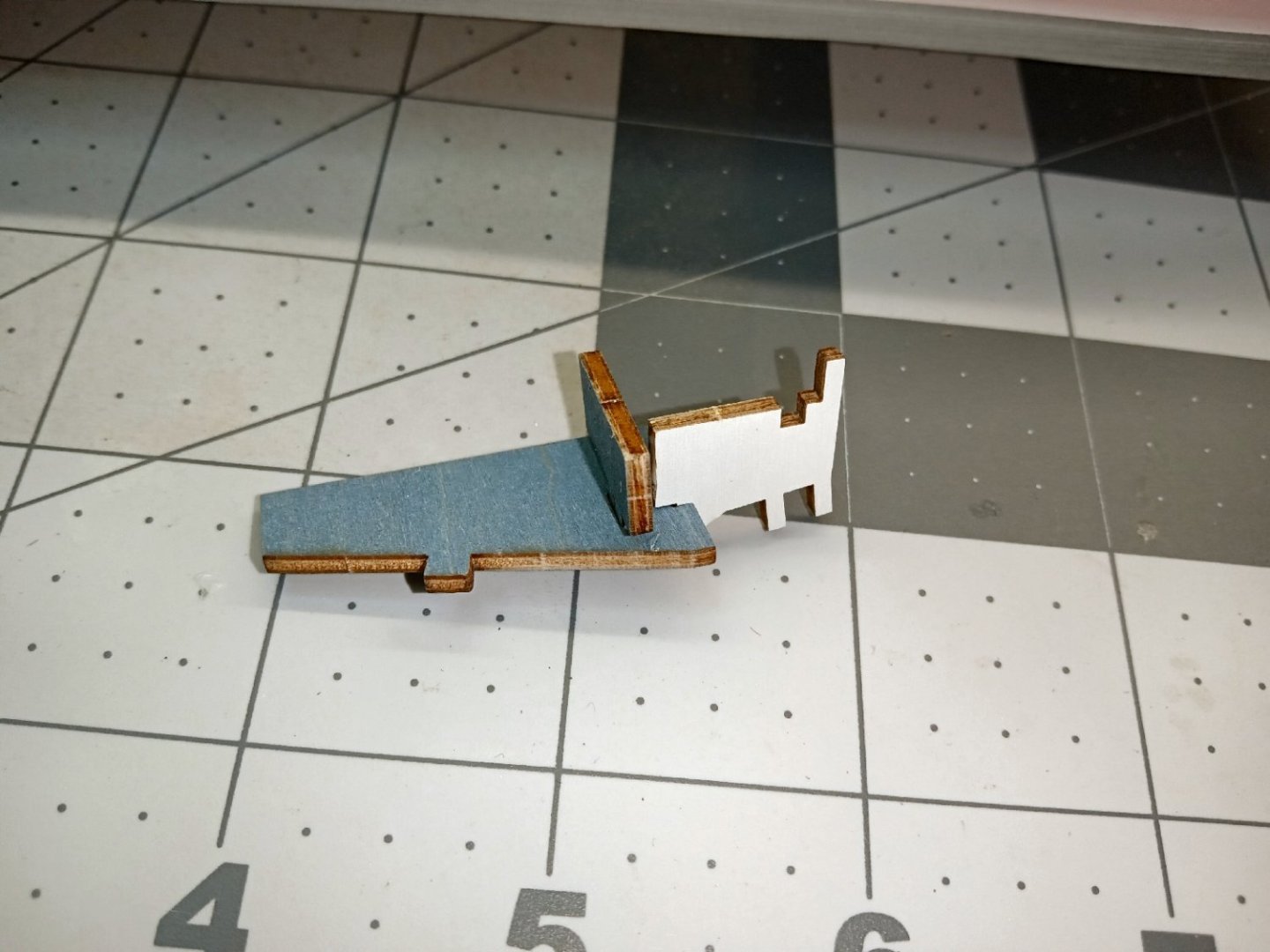
A few pieces of the top ply on either side of the tail fell off and were lost when it broke. I glued the tail in place, and let it set overnight. I then spent a couple days building up the surface with layers of the Canopy Glue. After the glue had completely dried, I painted the damaged area and the lasered edge with white paint.
Here on the backside, you can see a slight bump of extra glue on the corner, after the paint dried, I carefully sanded this off. The cat was now whole again!
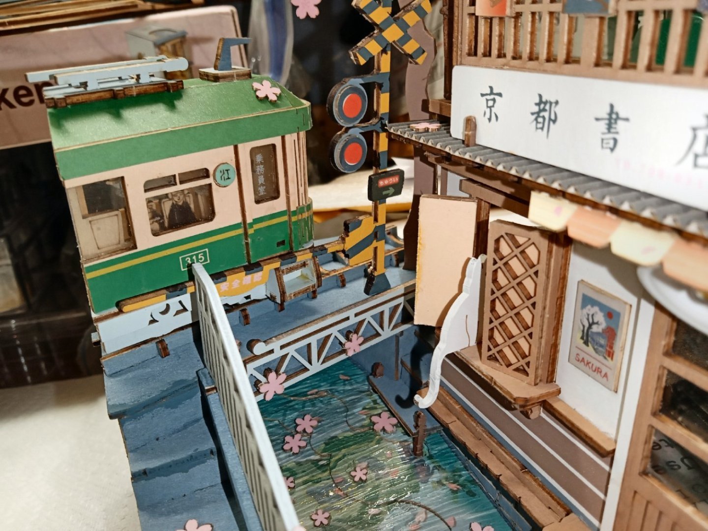
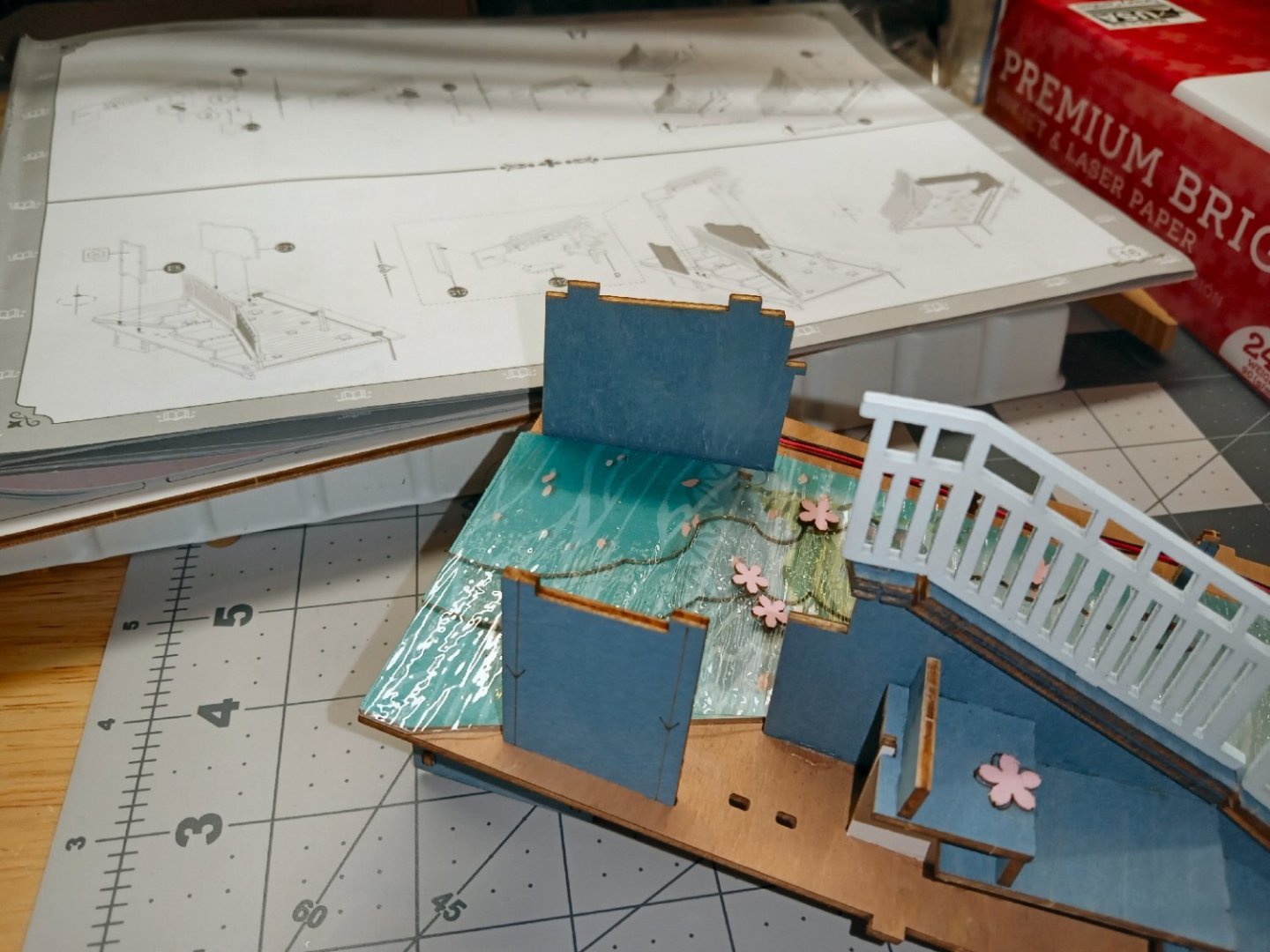
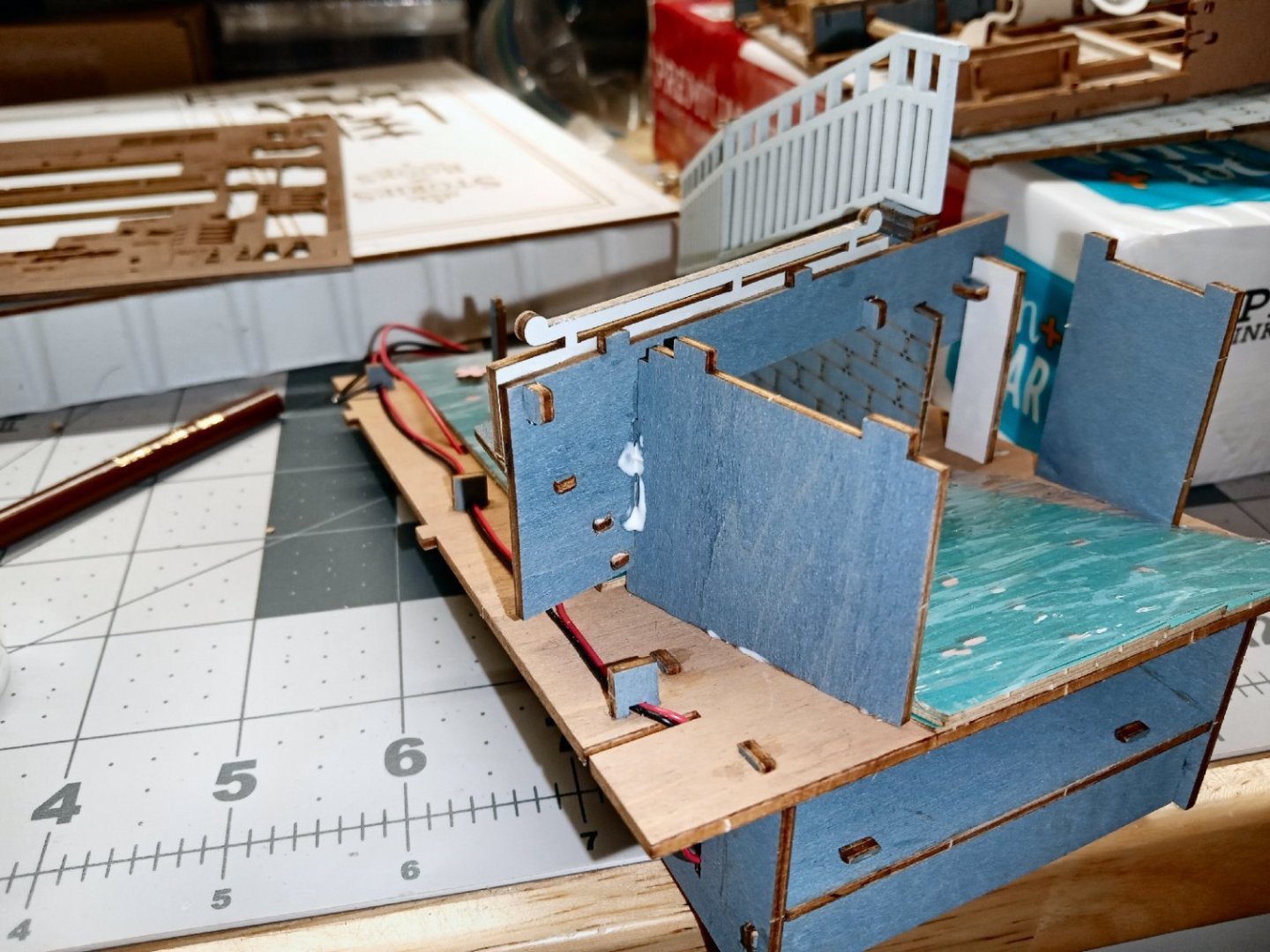
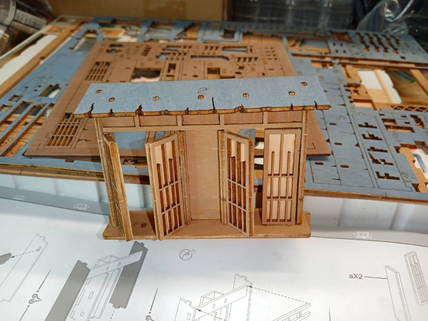
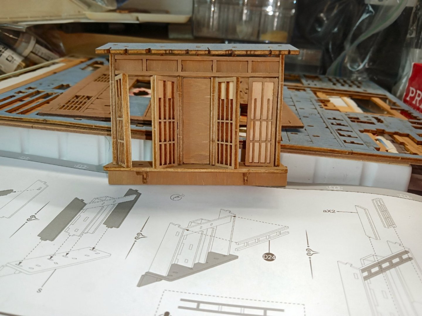
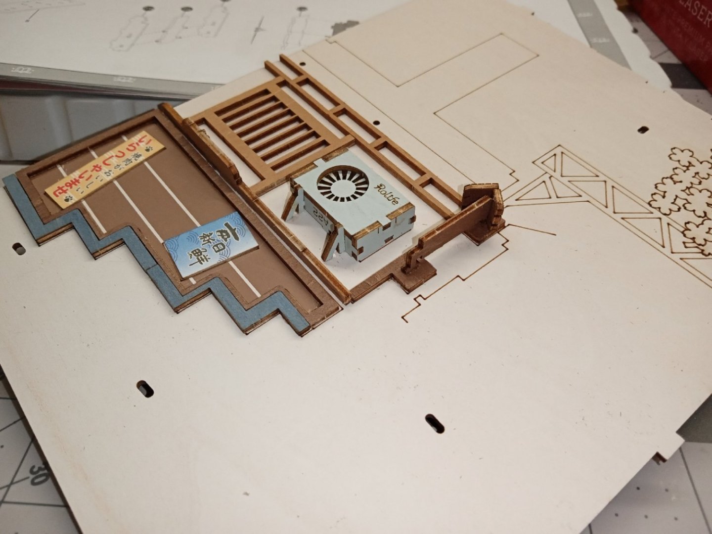
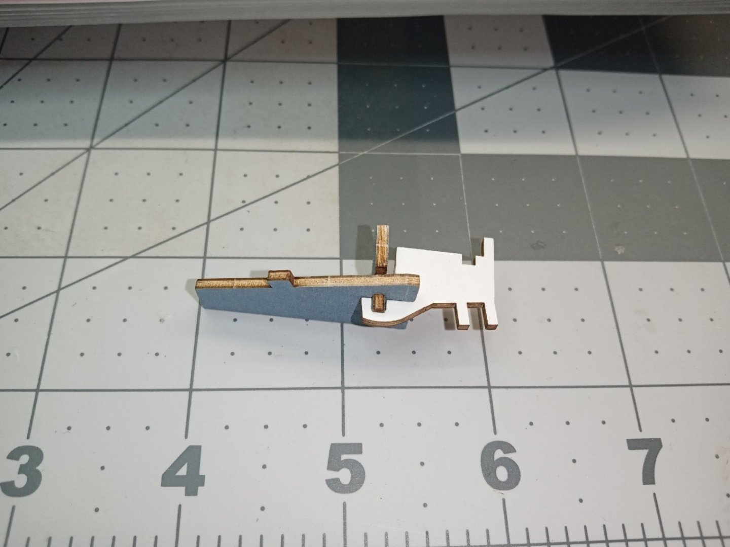
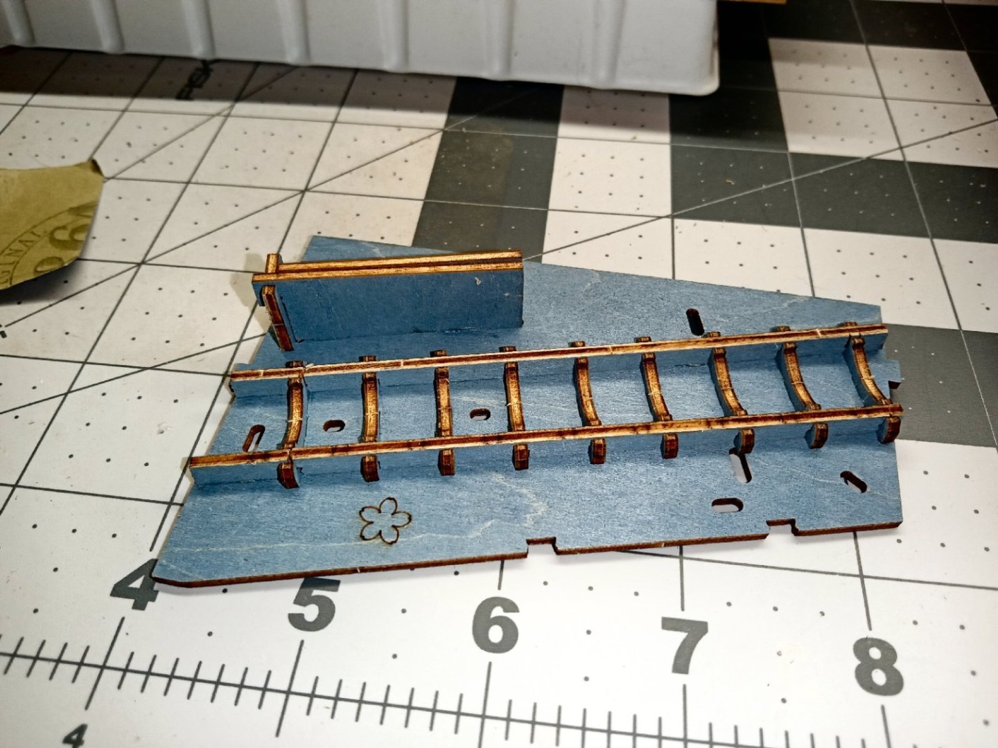
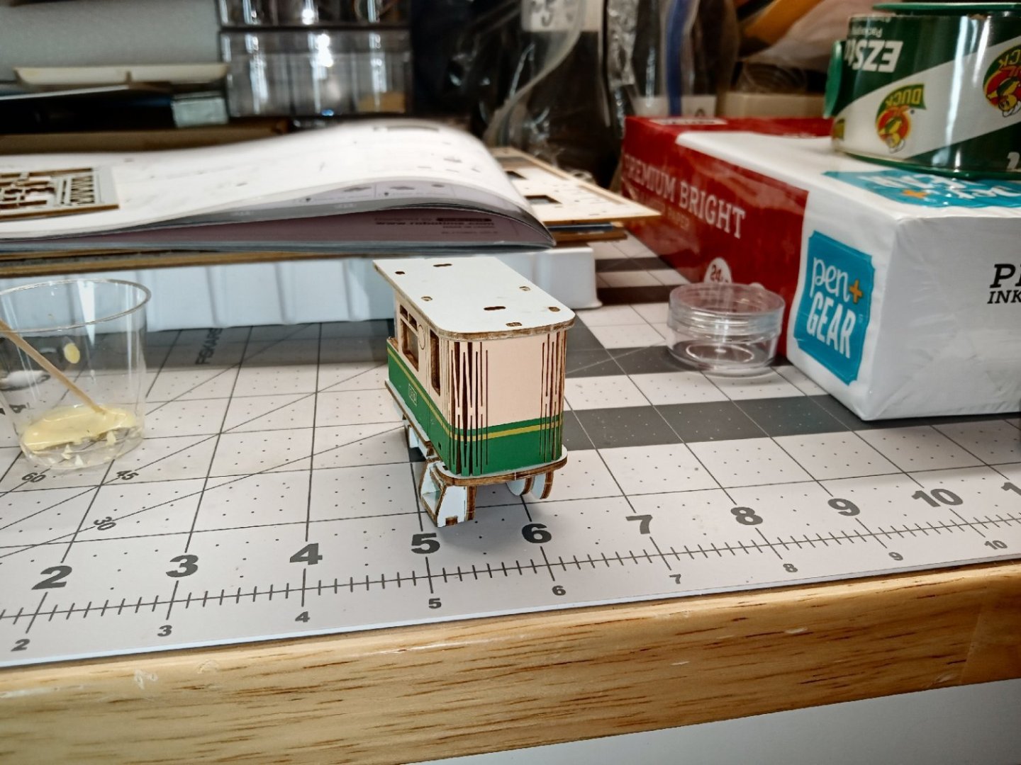
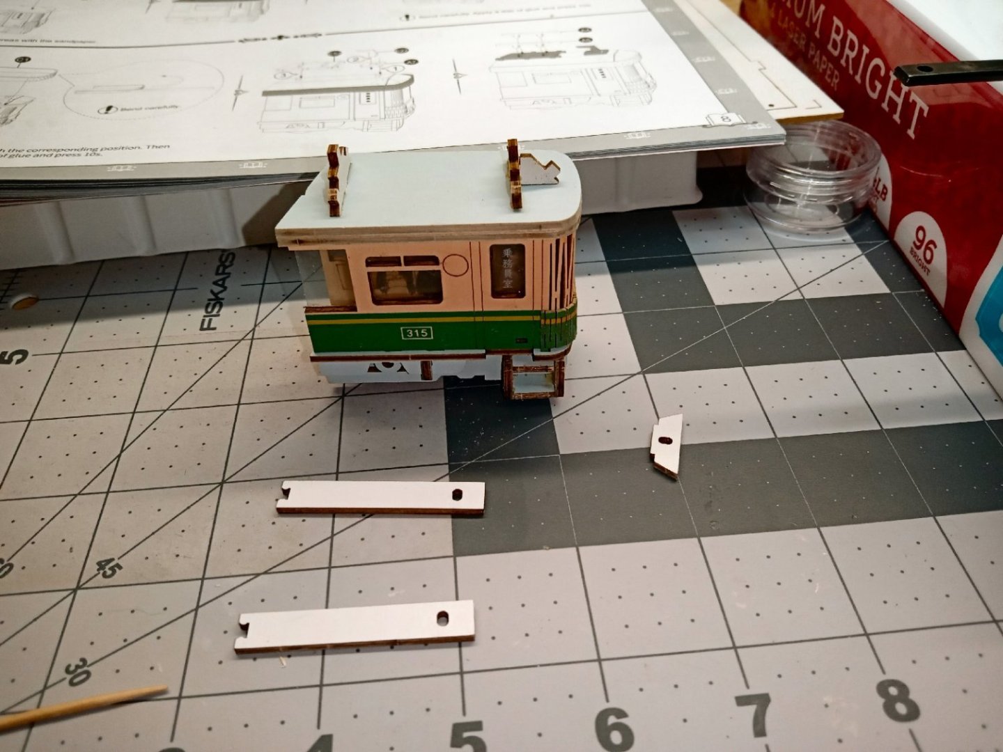
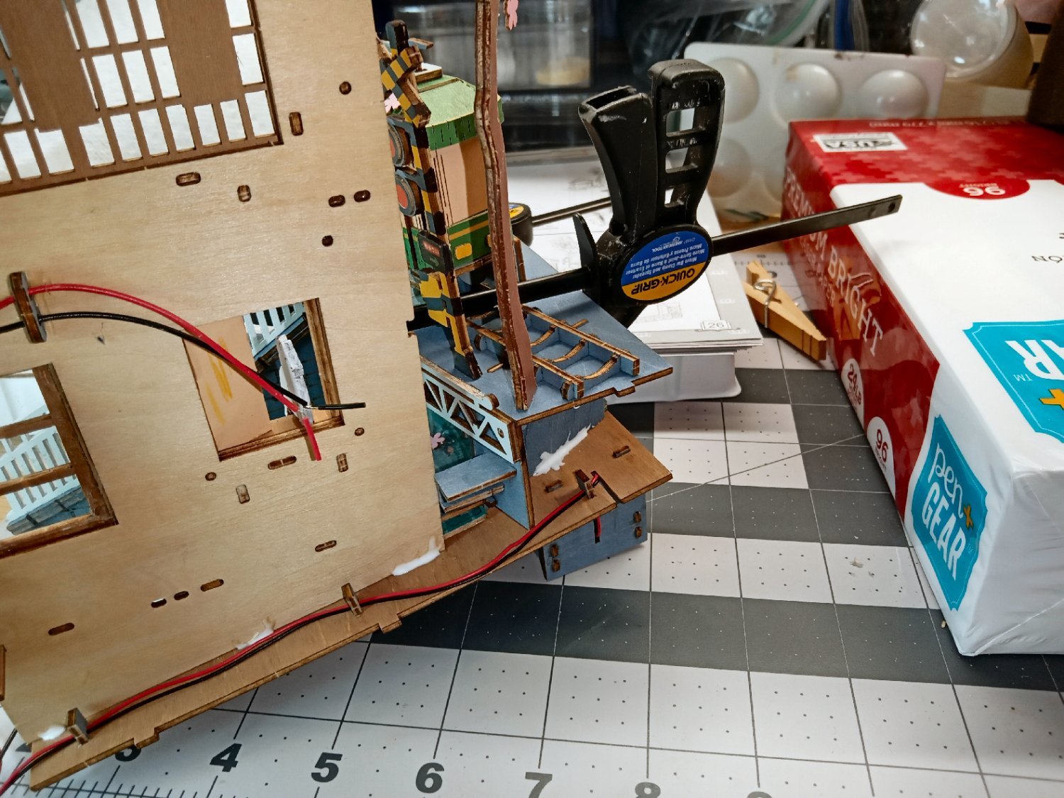
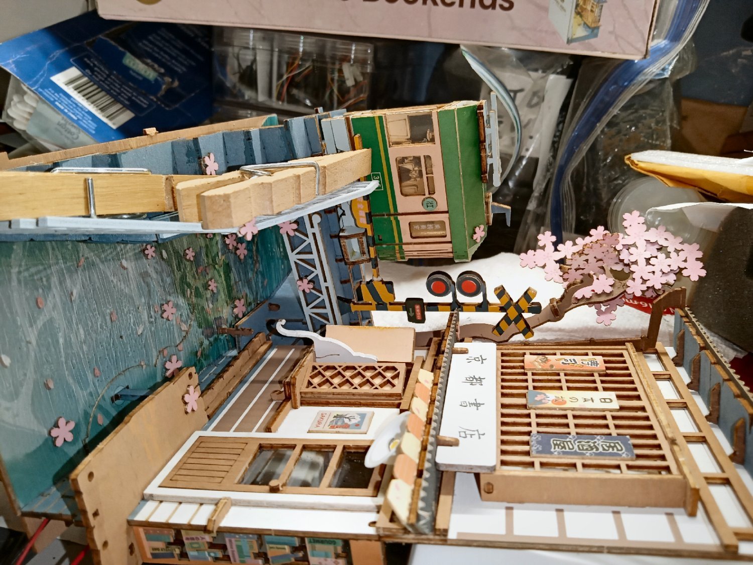
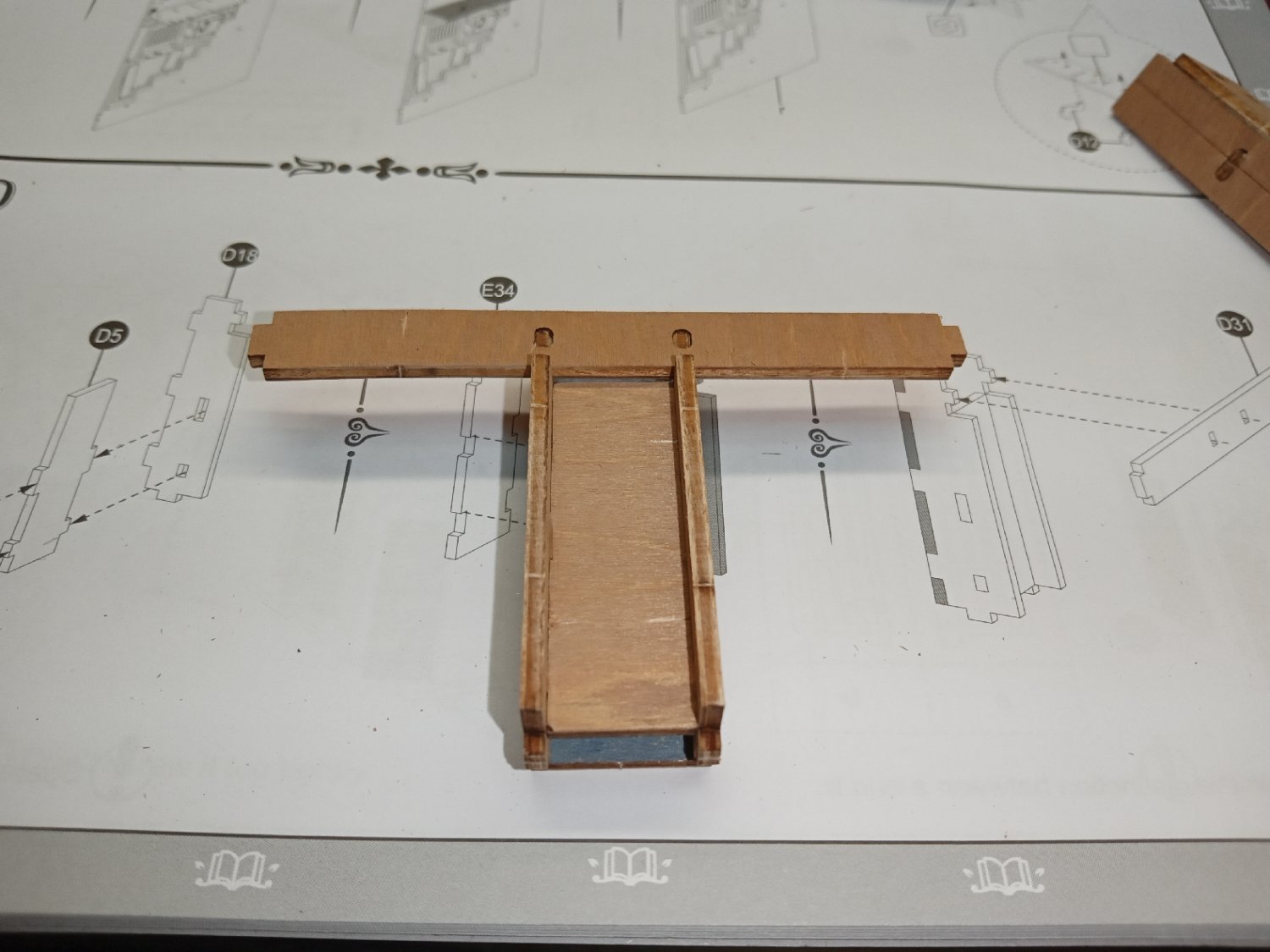
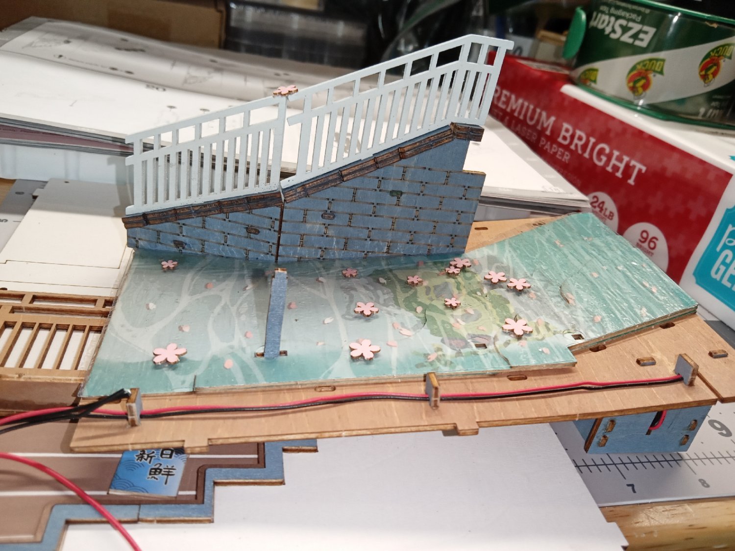
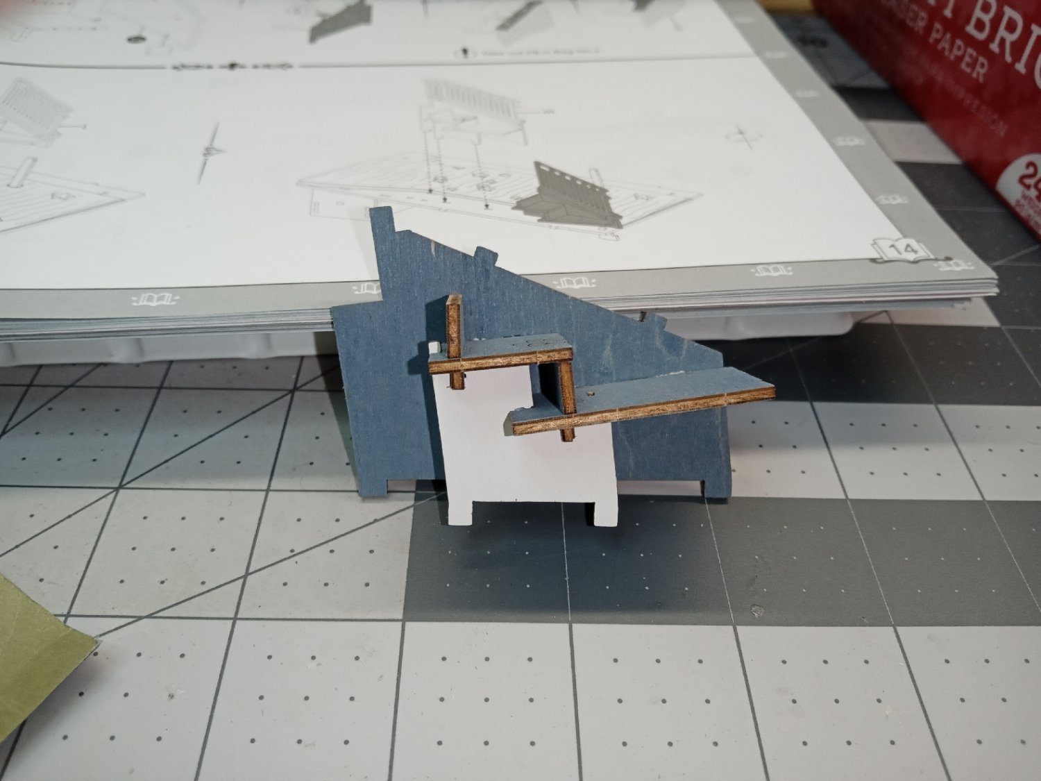
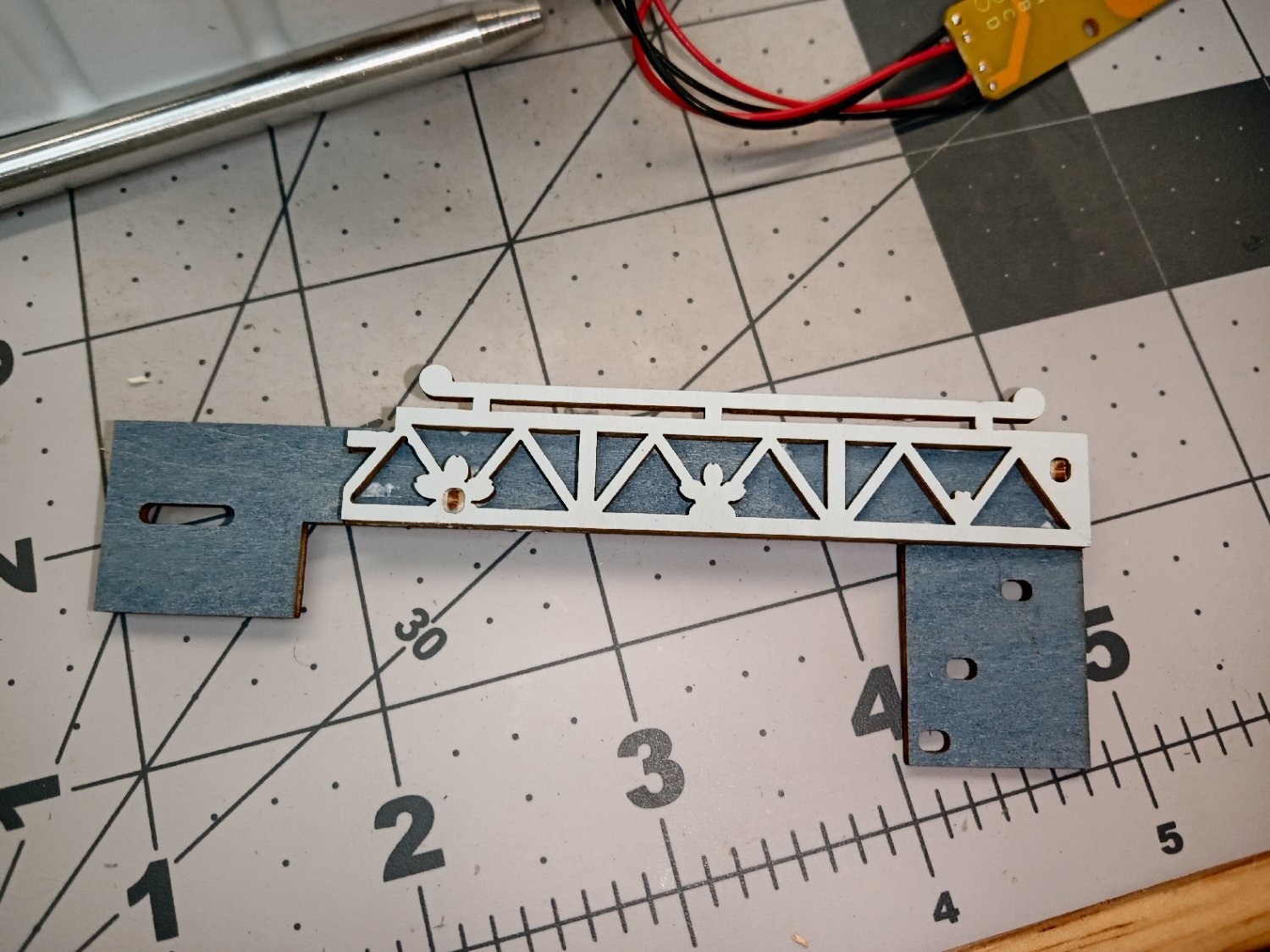
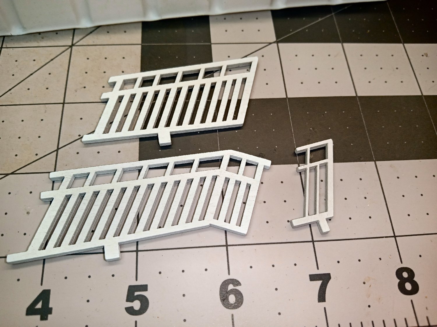
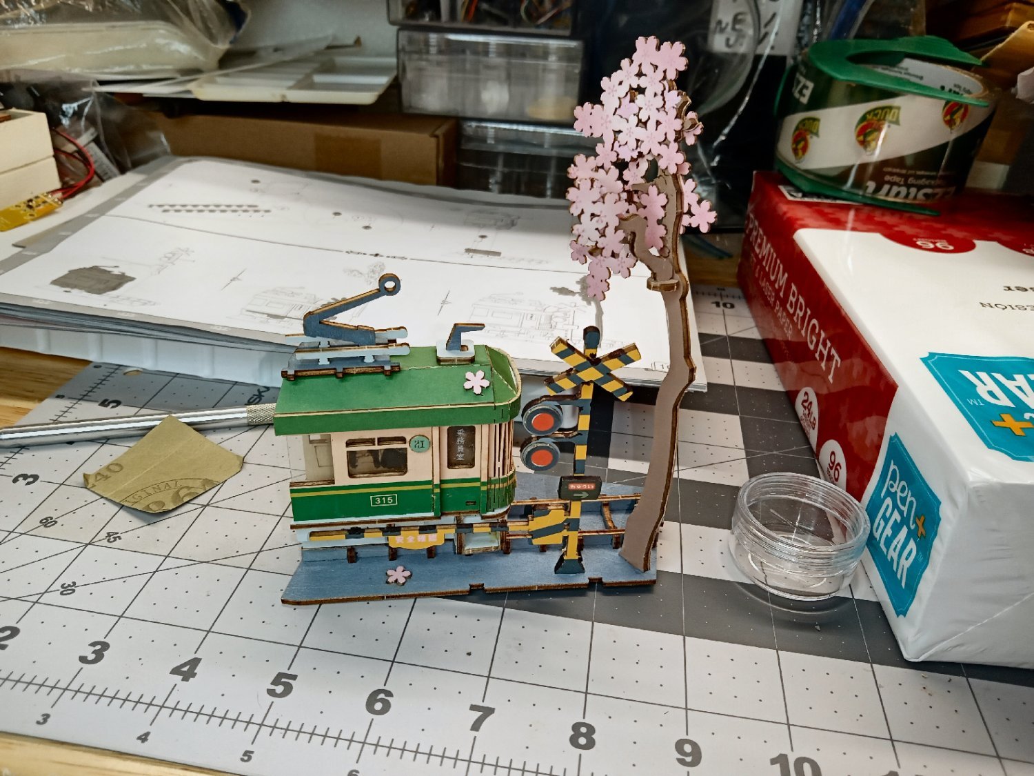
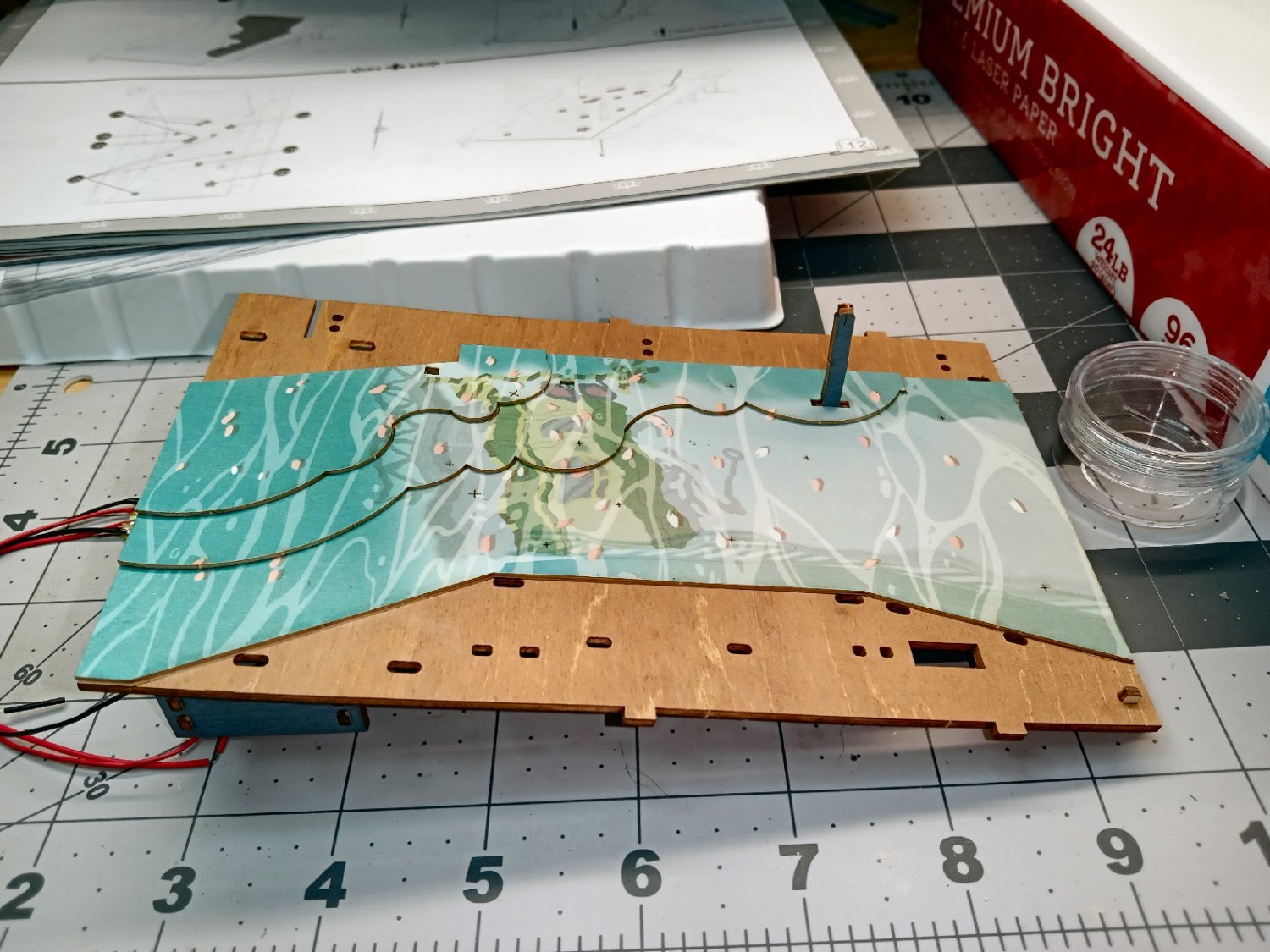
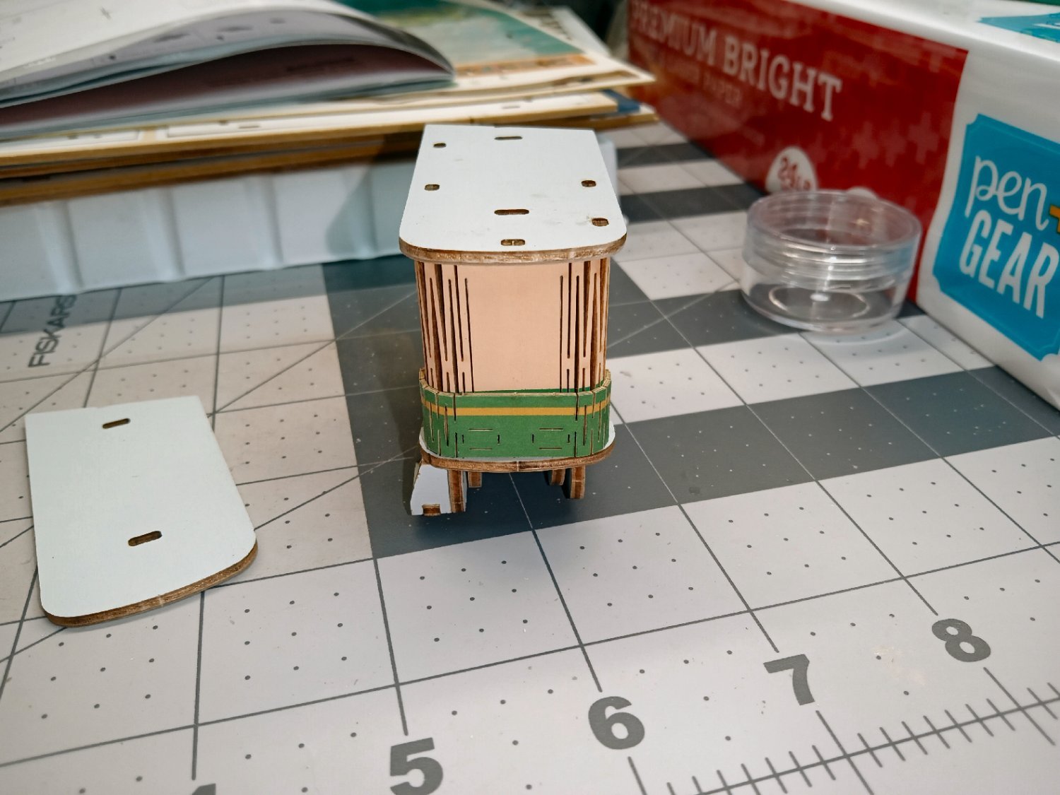
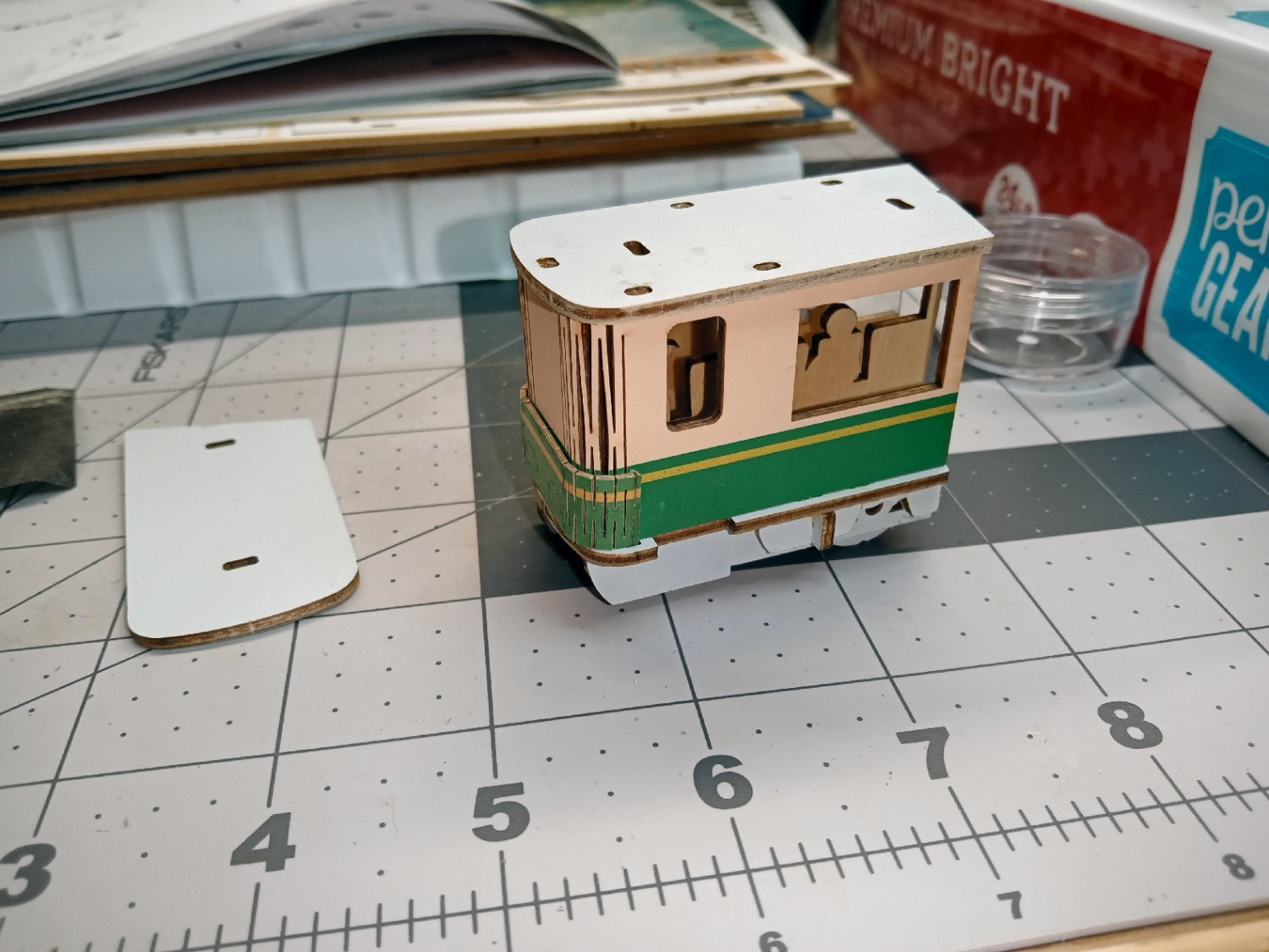
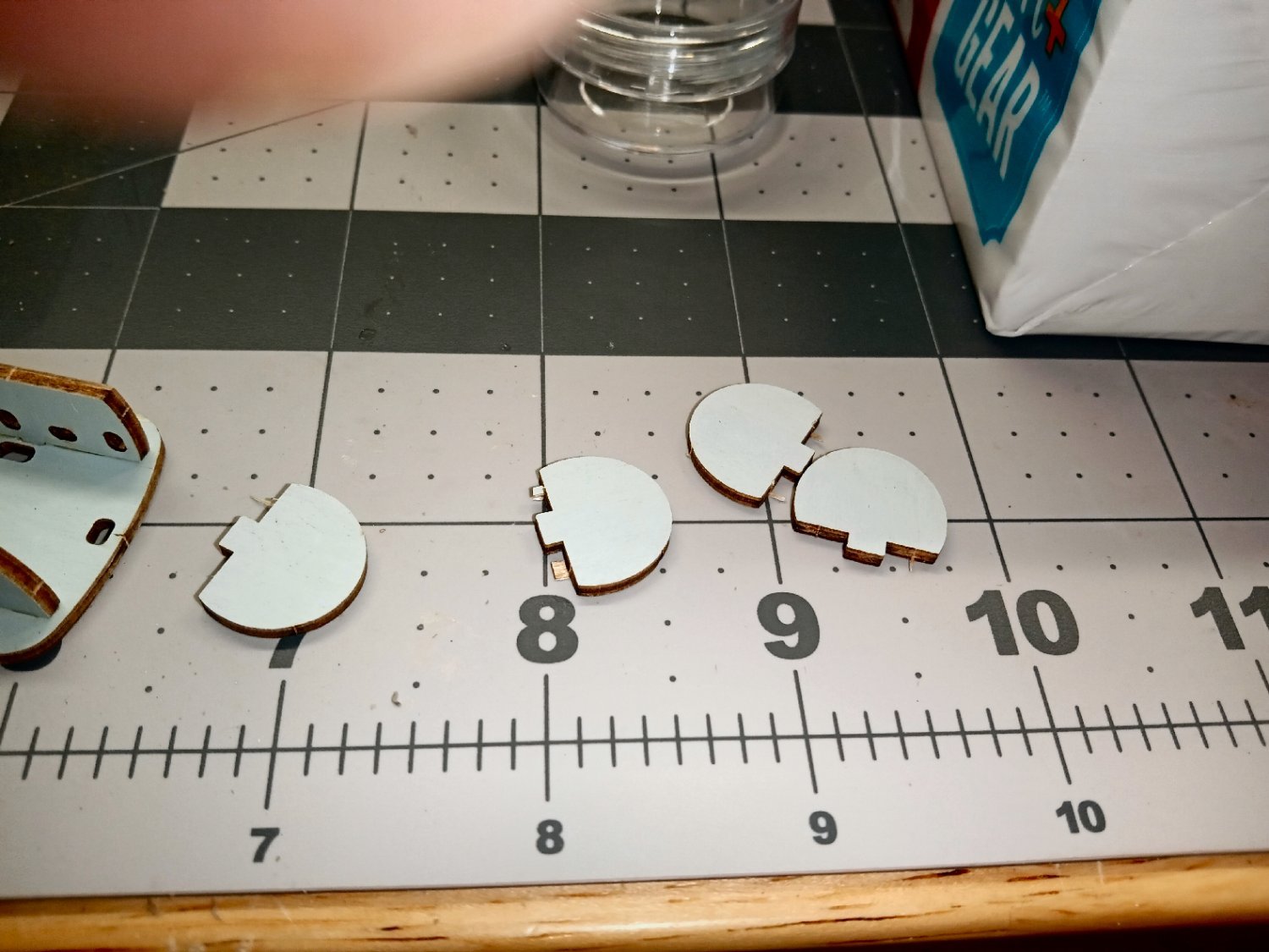
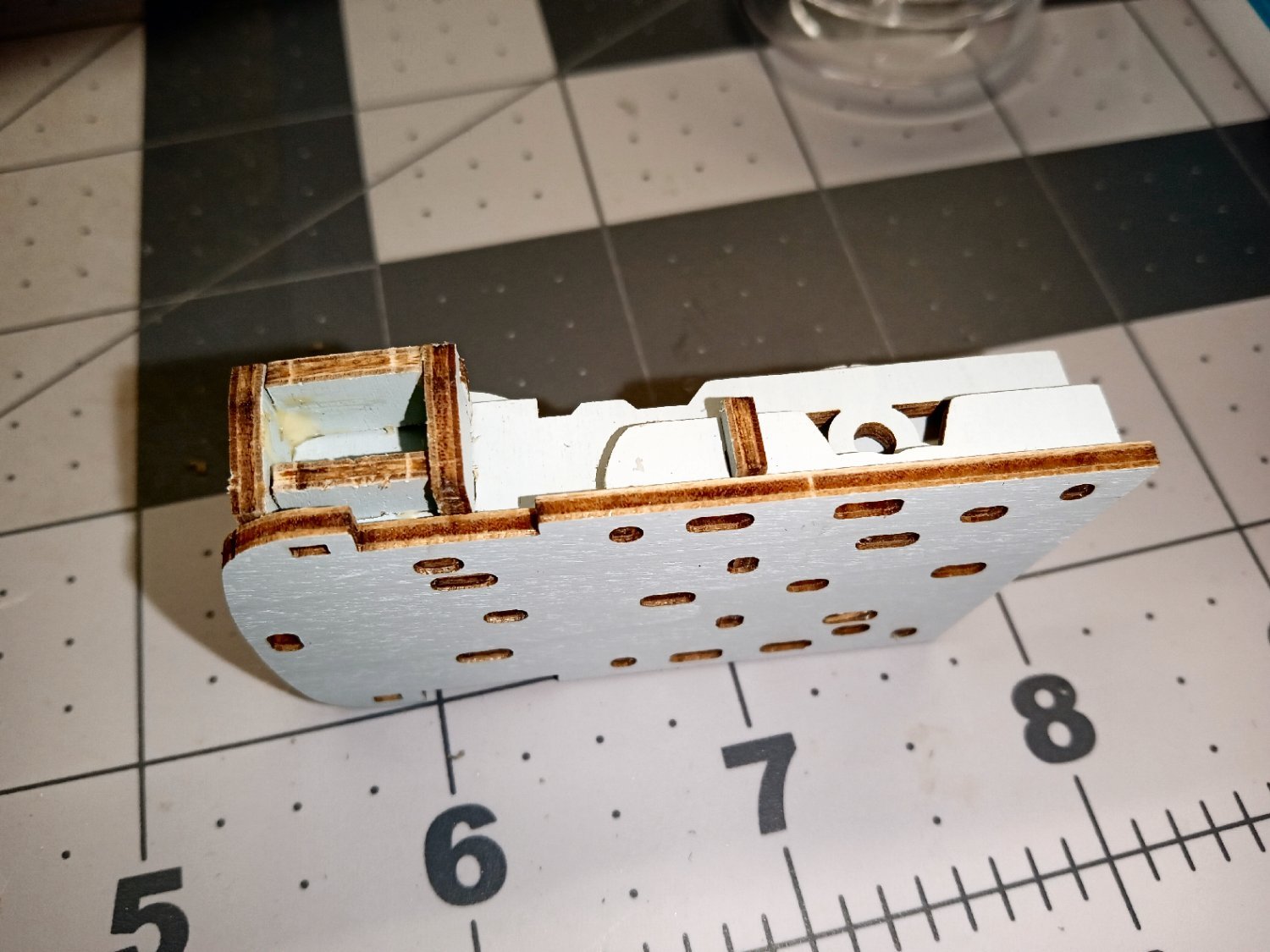
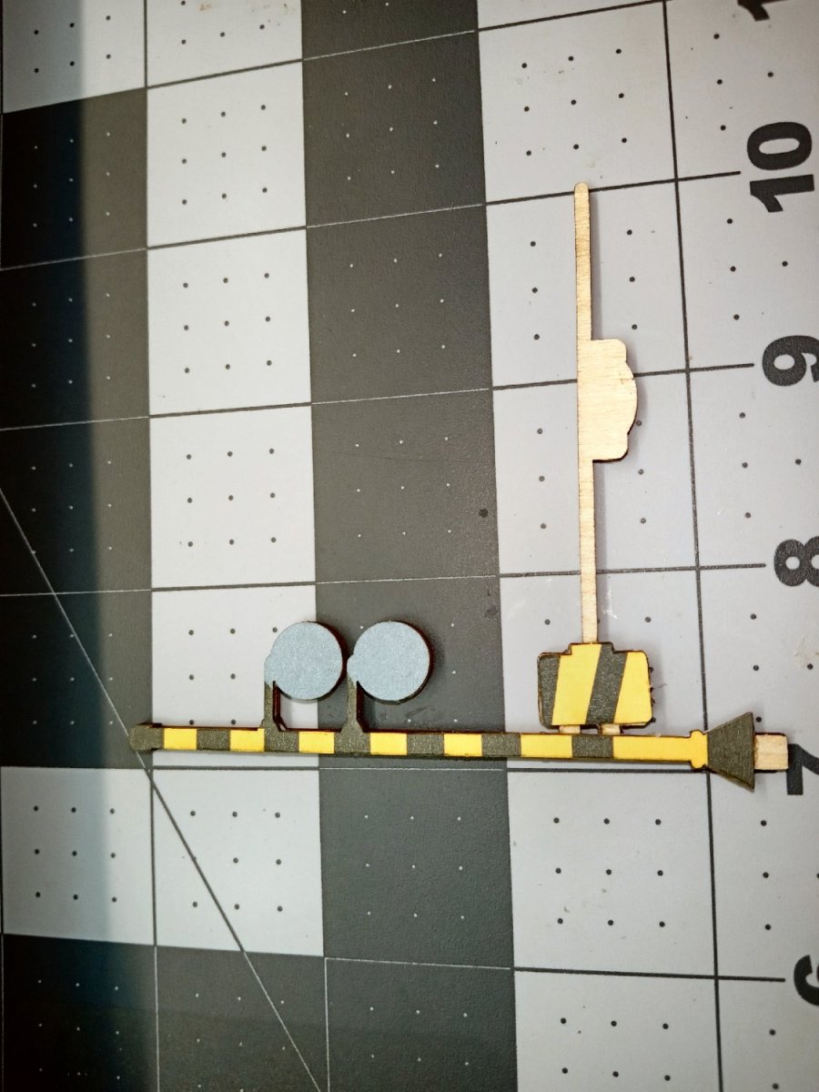
Now comes the assembly of the wall and tram assembly to the base. This picture shows the three sections ready for attachment.
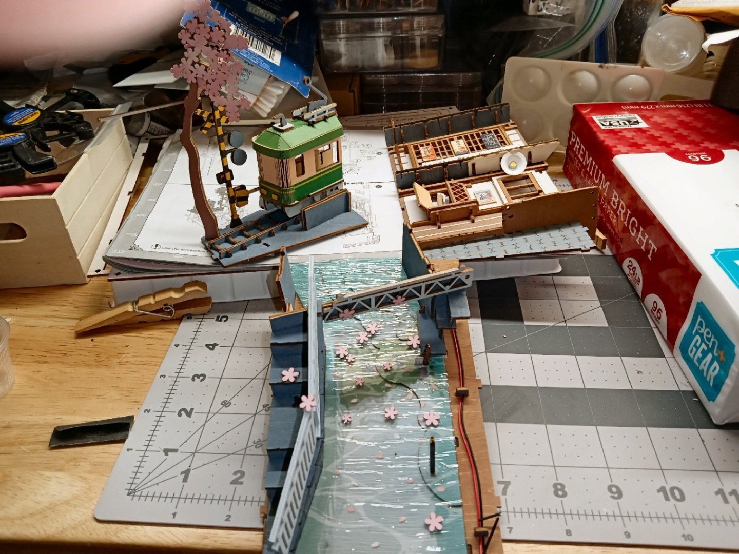
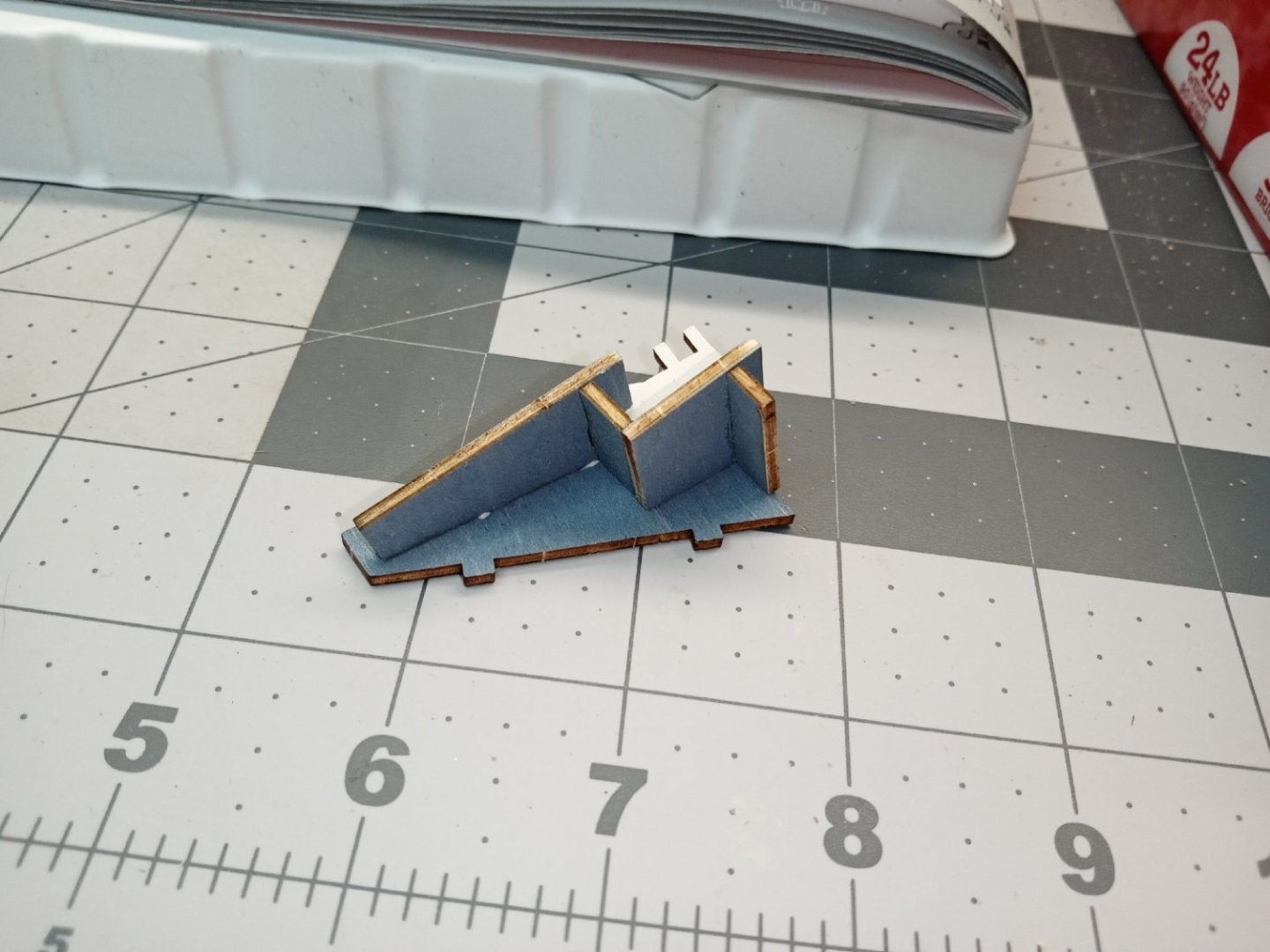
The wall goes on first. No glue yet.

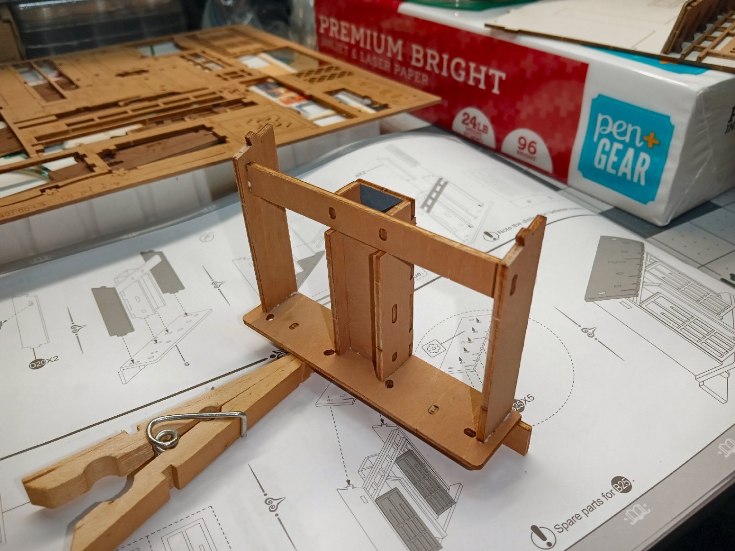
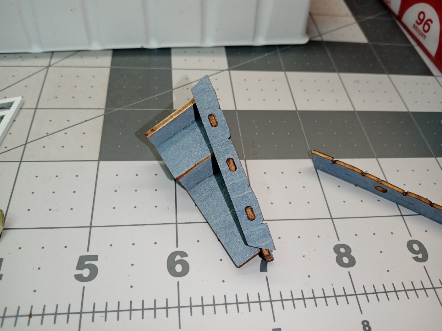
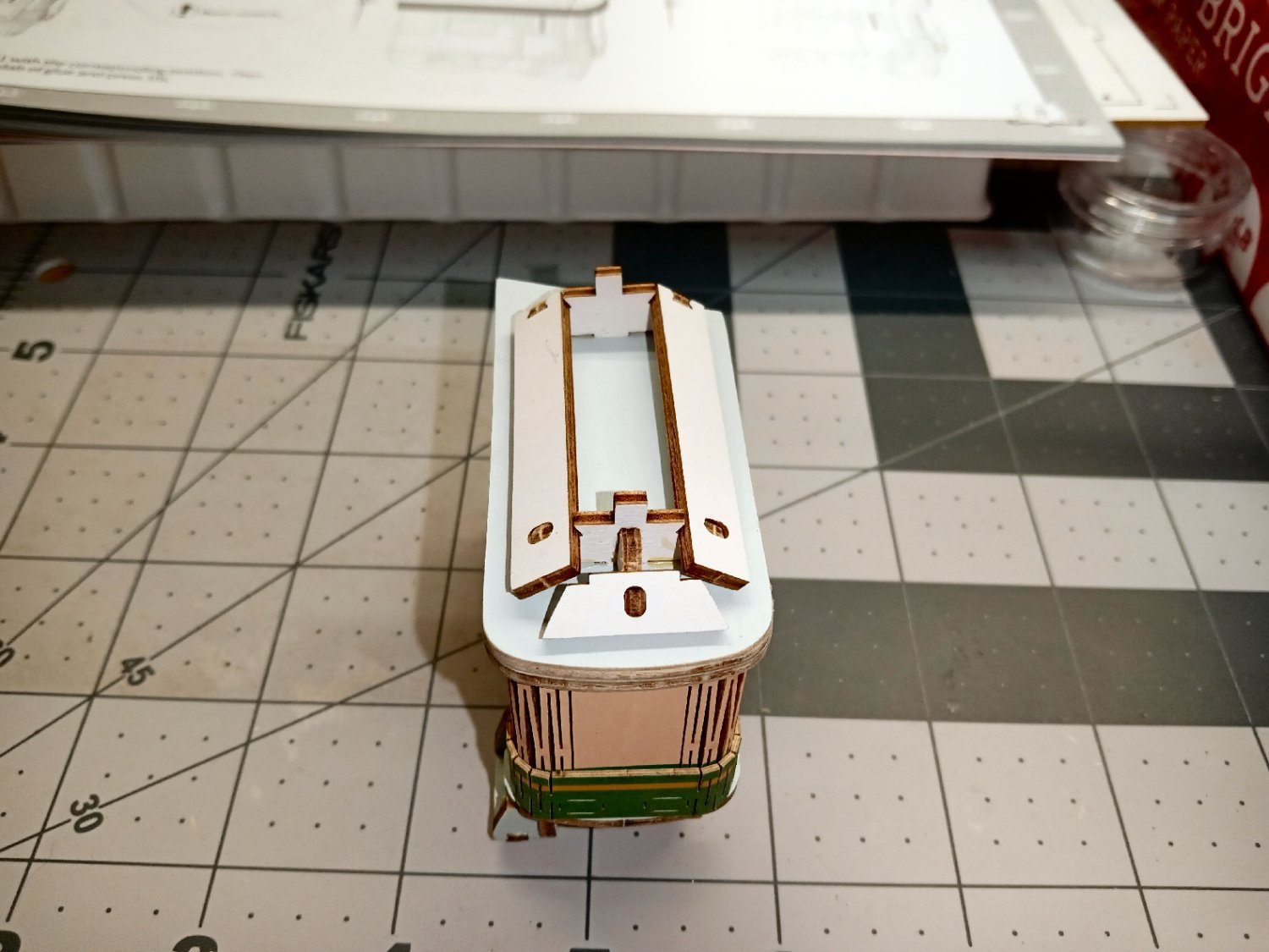
After ensuring that everything lined up, I applied glue to the outside edges.
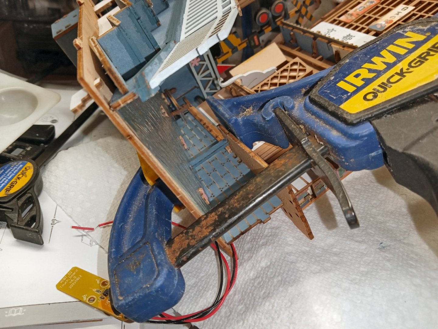
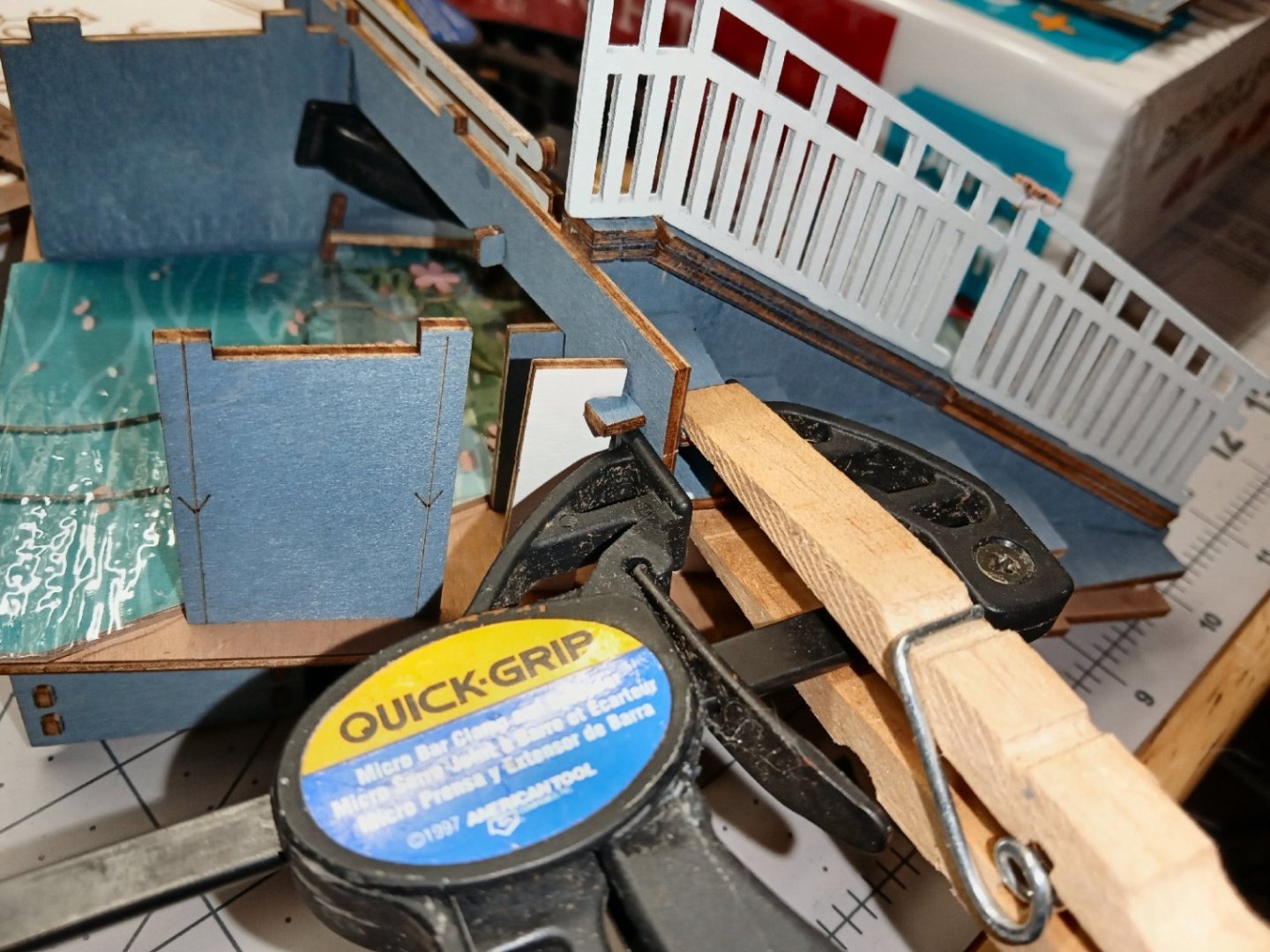
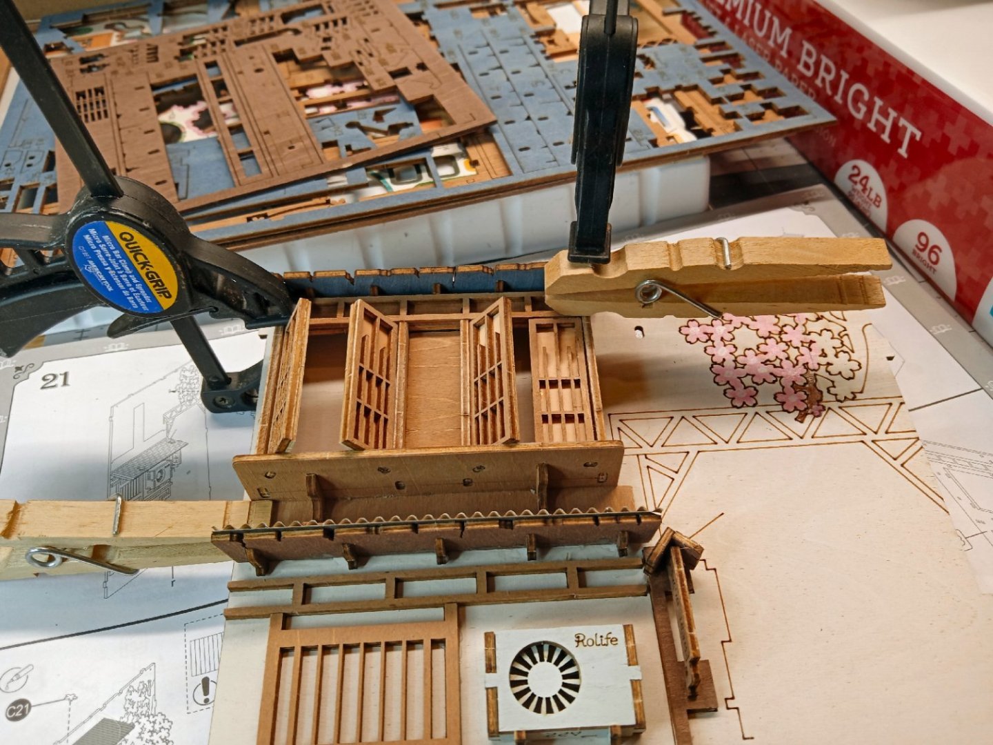
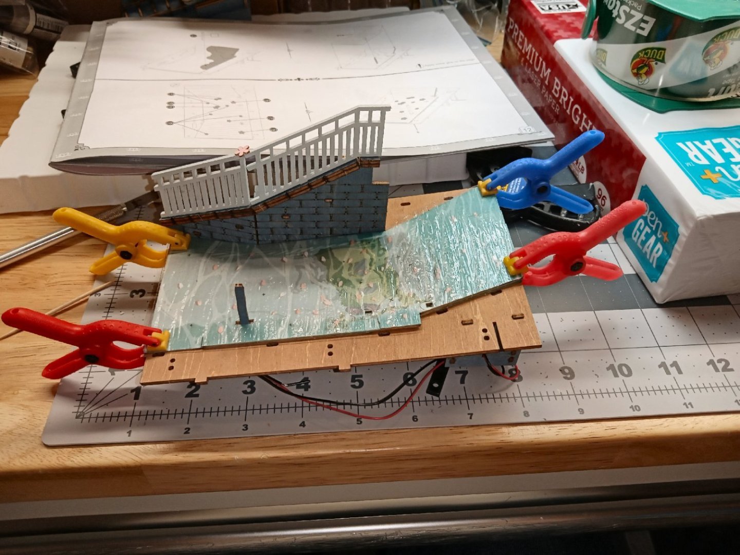
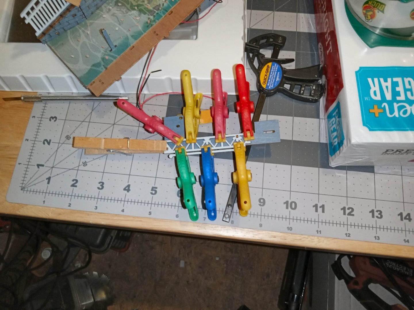
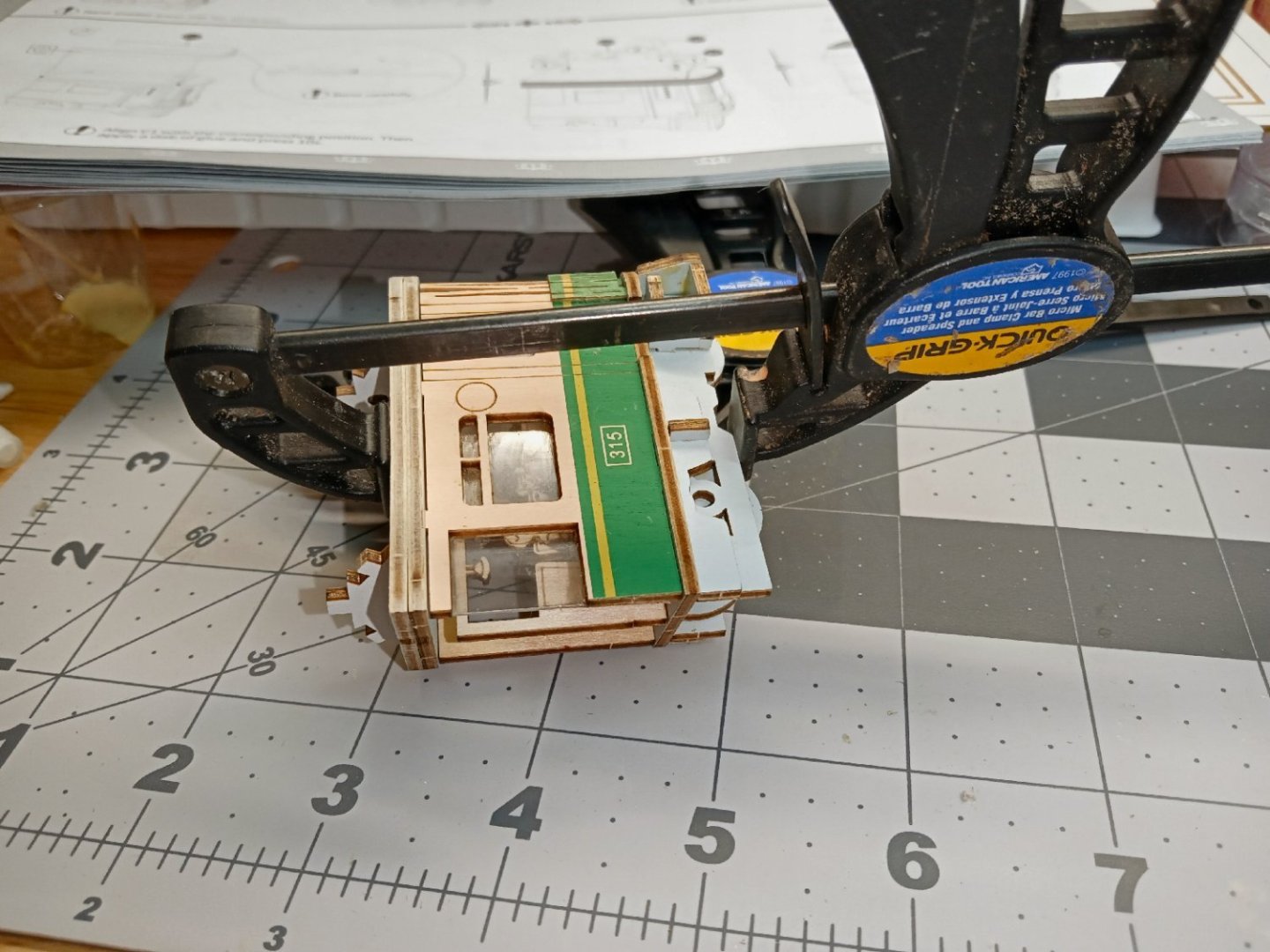
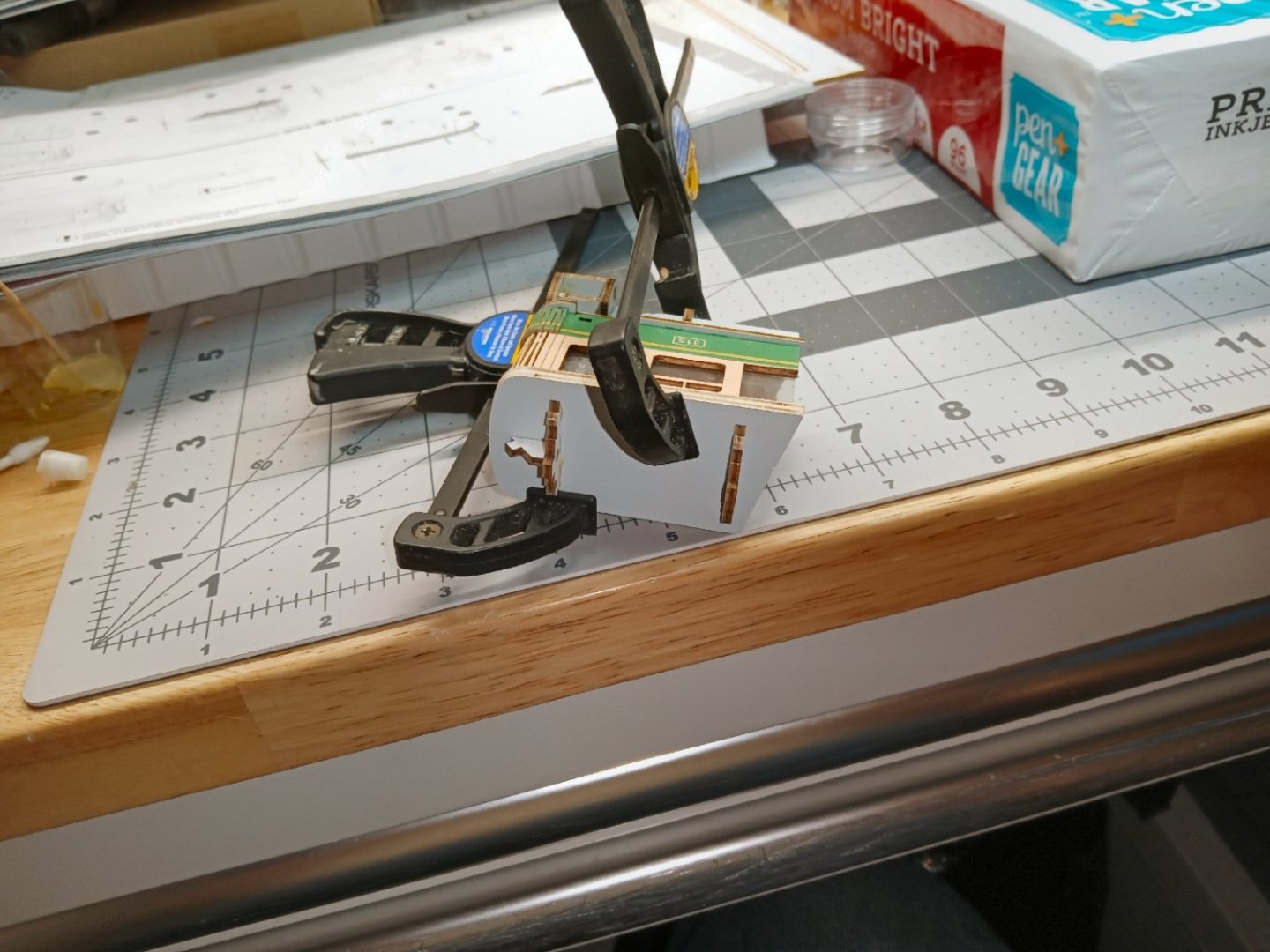
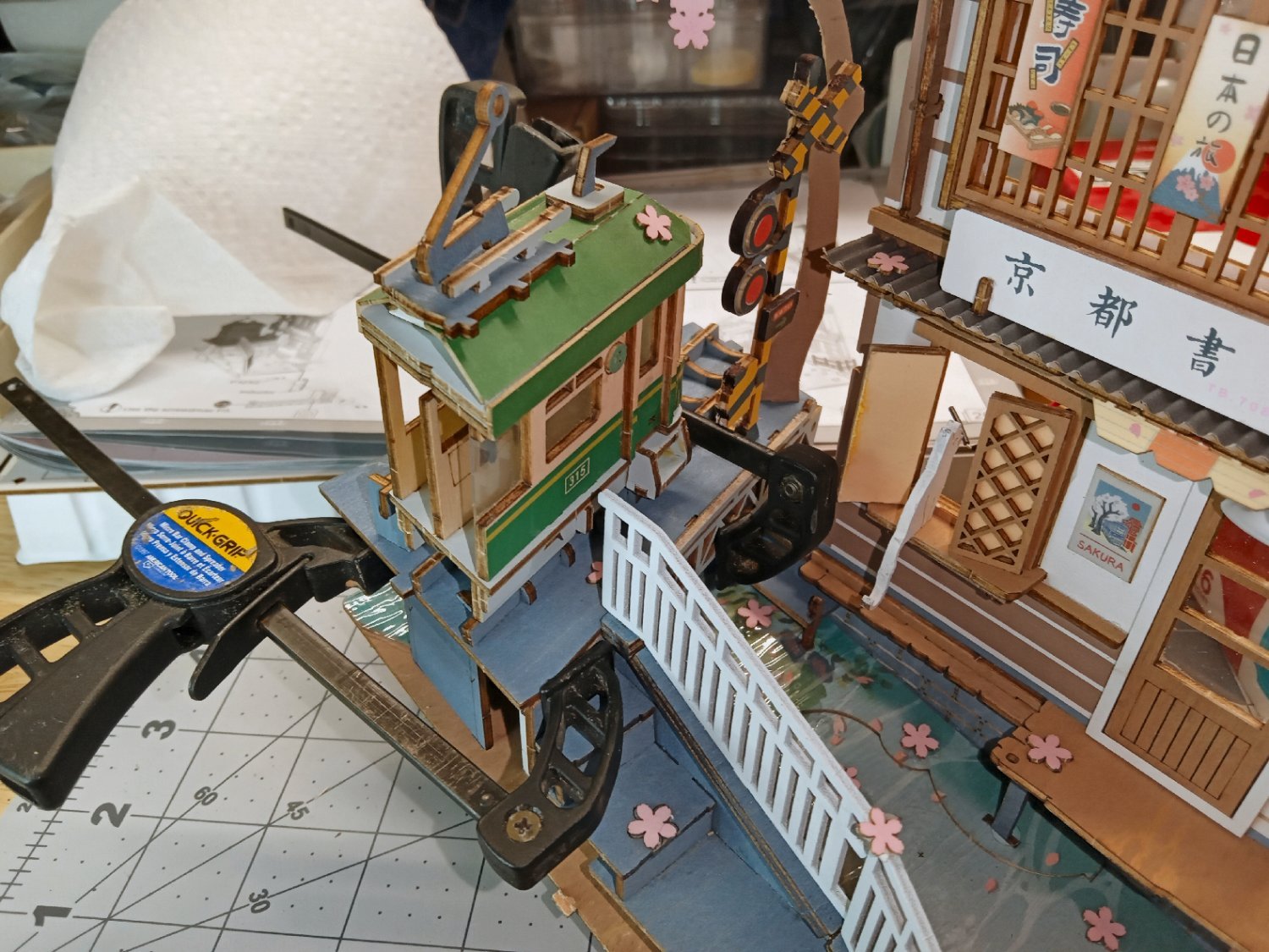
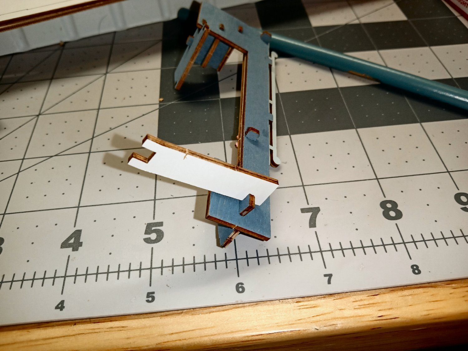
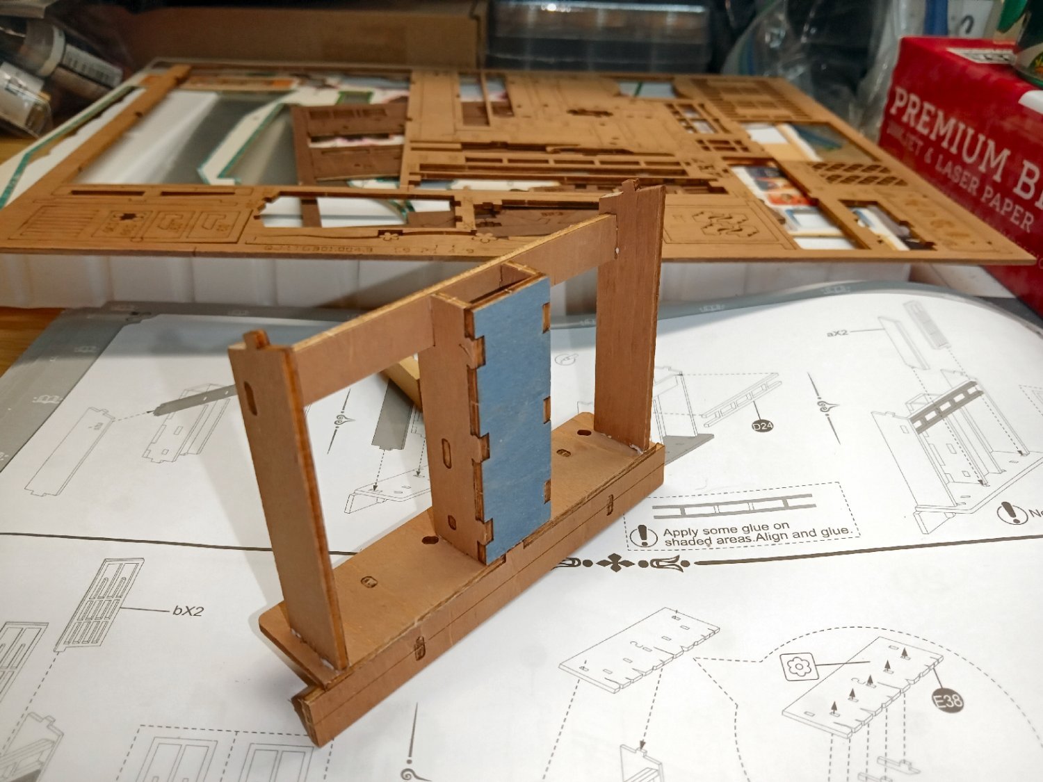
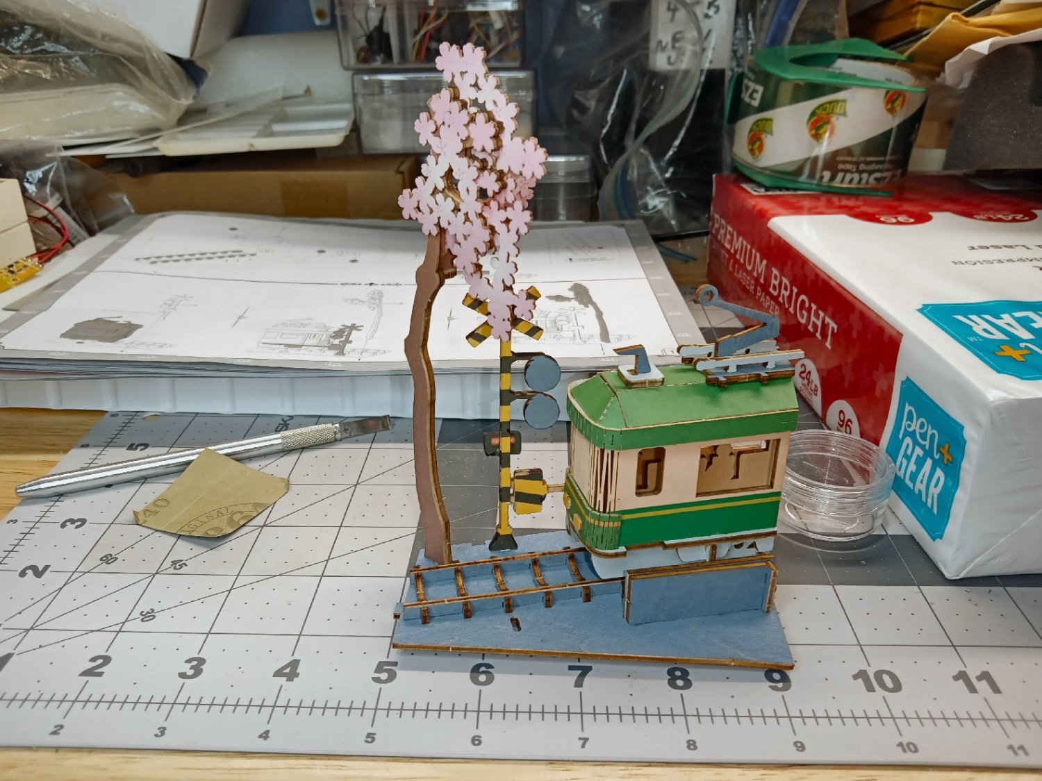
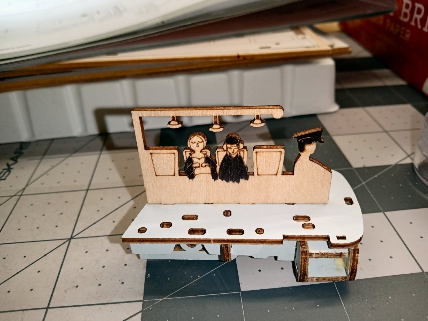
In order to get the bridge surface and the front beam to sit correctly together, I had to clamp it. Sharp eyed modelers will note a problem with this picture. The cross arm on the crossing gate is missing in action! The arm broke off while I was trying to get the tram assembly in place. This made it easier to place the central clamp, but what a pain! The arm was located and will be glued on later. If you build this kit, I would recommend waiting until after the whole bridge is together to attach the crossing gate and the tree.


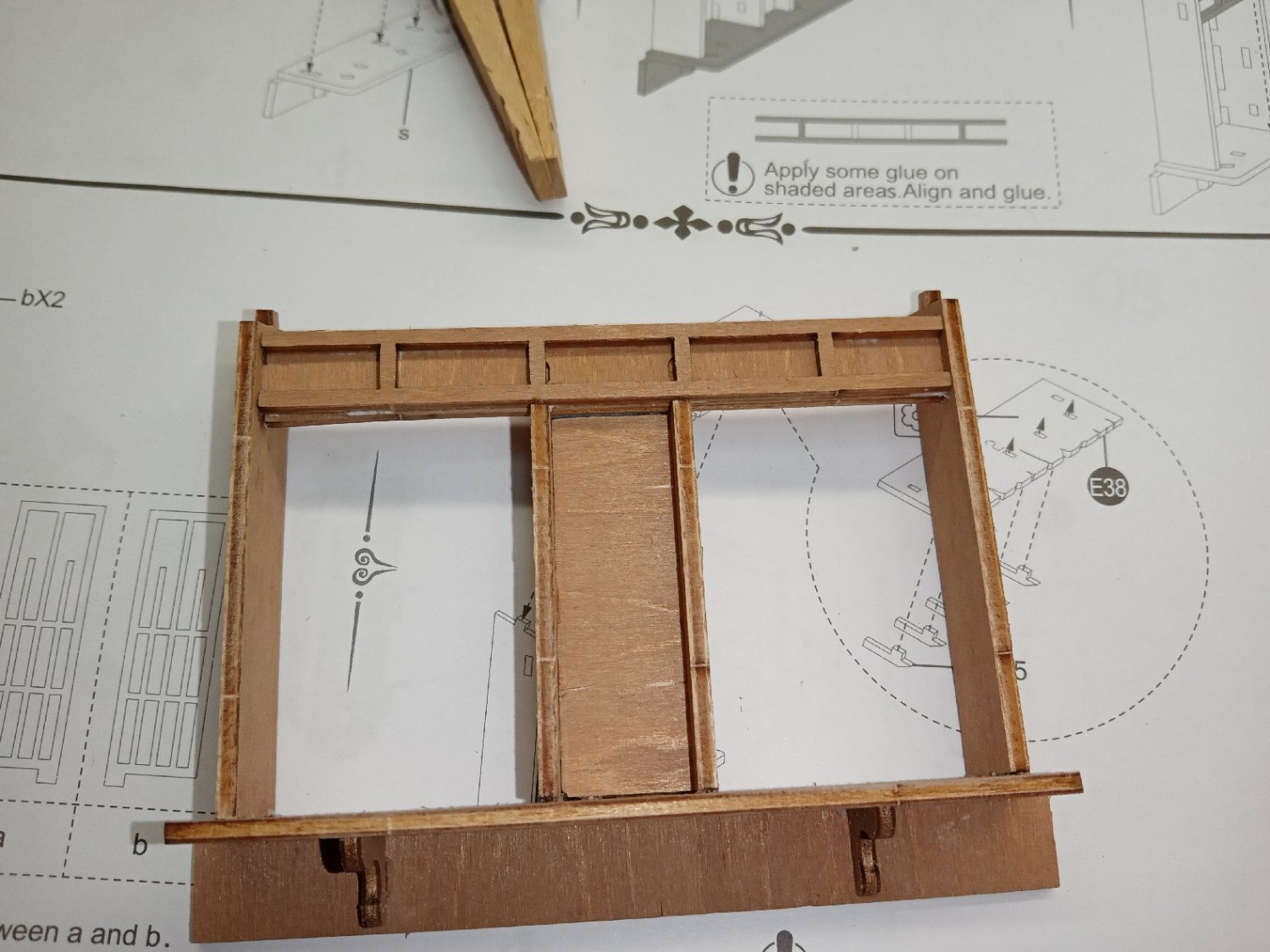
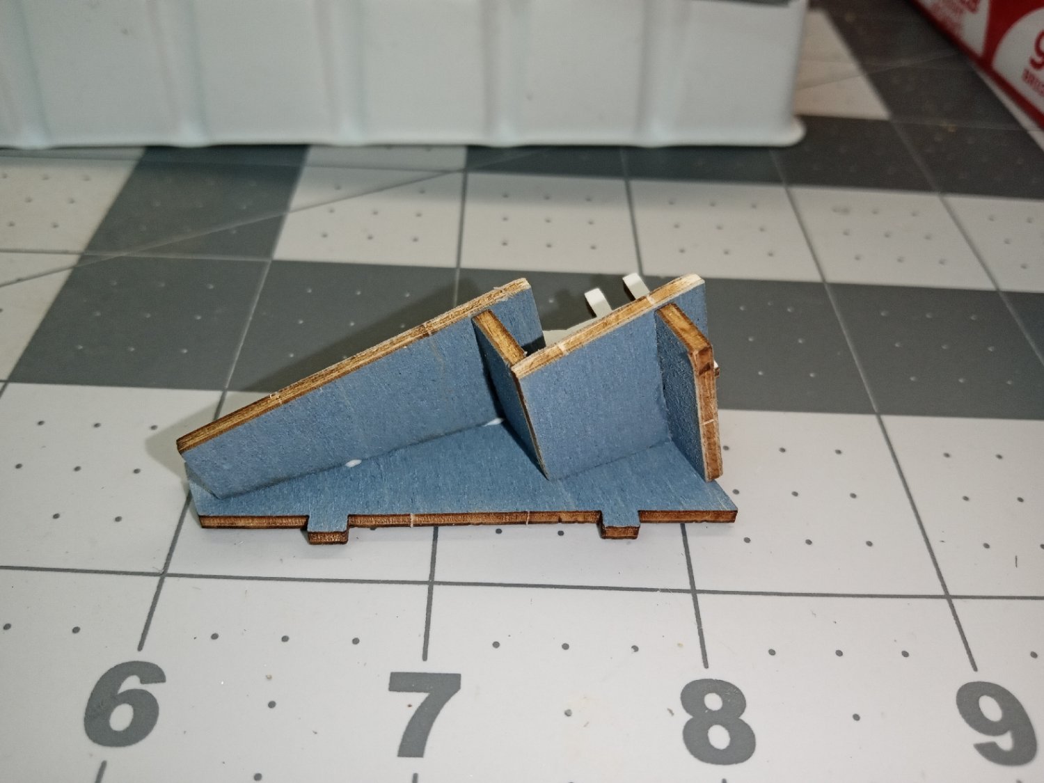
I also had to clamp the pier that supports the porch, as the tab would not sit properly in its slot.
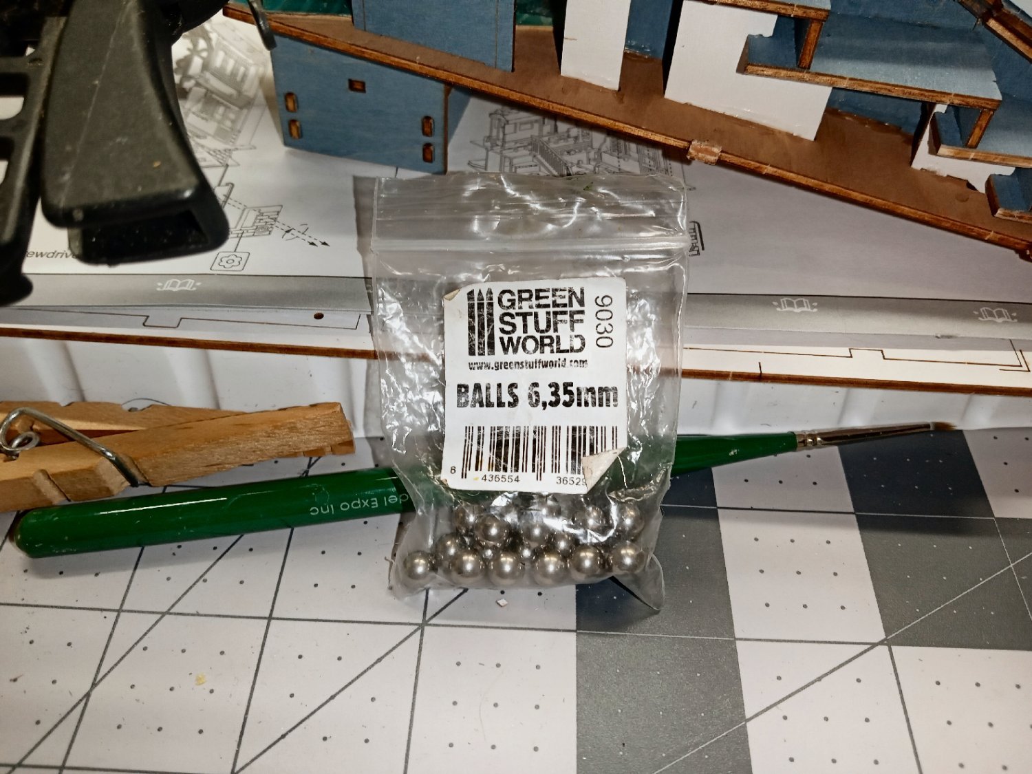
Up until I repaired the cat, I have been using the colored pencils on the exposed edges, with fair results. But one of the upcoming parts to go on is the front of the case. This has long prominent edges, especially were it meets the stream bed. The pencils just are not enough for this. I decided to mix a custom paint color using my stash of Vallejo paints. The Vallejo bottles have a very small opening, even after you pull of the dispenser tip, so manually stirring them is a losing proposition. To solve this, I put a small stainless-steel ball in each bottle, the first time I use it. The ones I use, shown in the photo below, are specially made for use with water-based paint. Regular SS balls can still rust, if left in permanently. I bought mine through the Web. I have 8mm balls I put in the larger bottles of primer.

I pull off the tip drop in a ball and replace the tip. Shaking the bottle until the ball rattles around freely does the job.
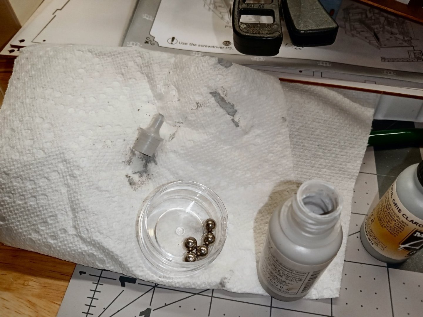
I put a large black spot on the label to show that bottle already has a mixing ball, using a Sharpie.
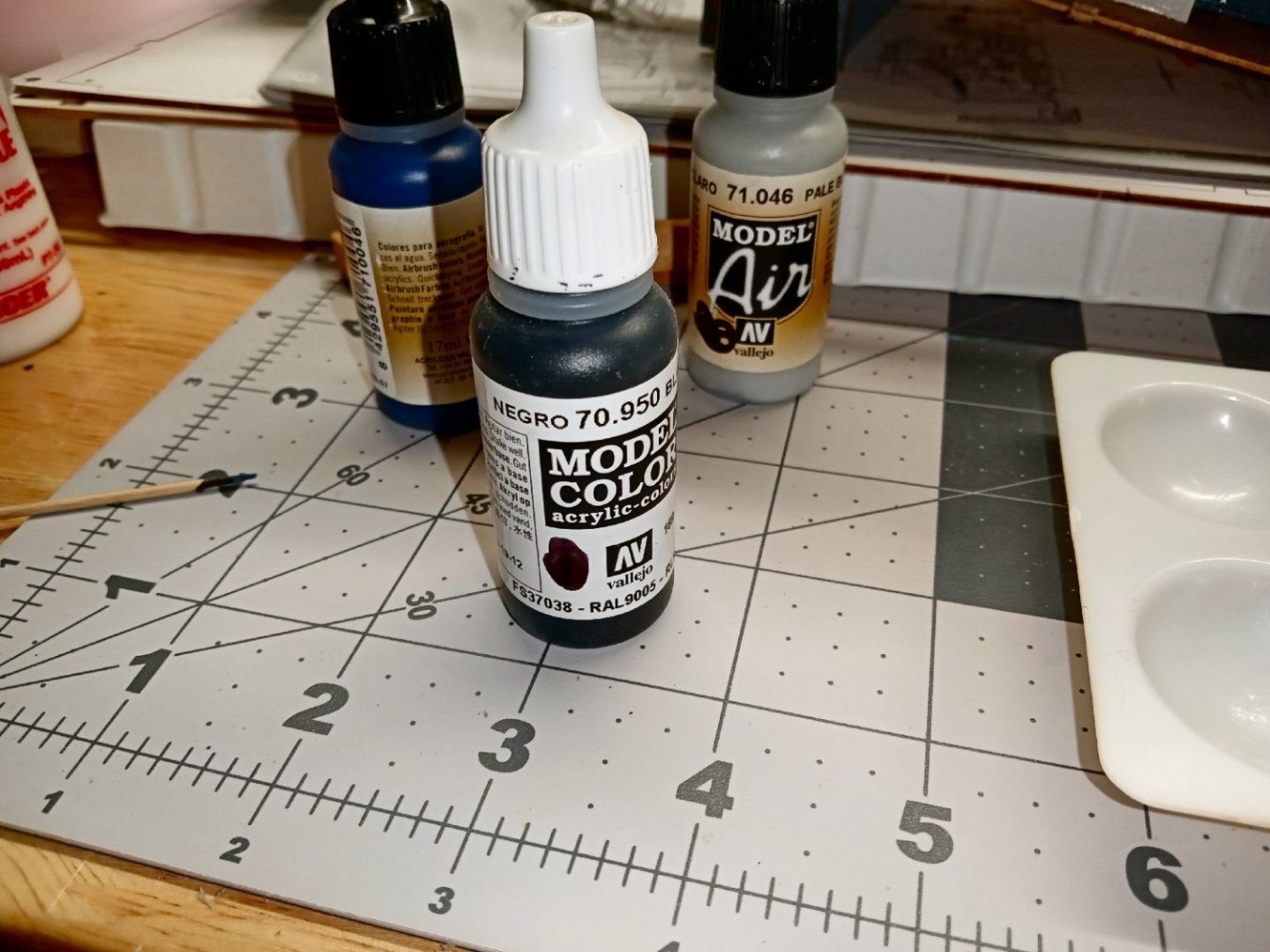
After some experimenting, I used these three colors (Pale Blue Gray, Black, and Blue) to match the masonry color used in the kit. It is just very slightly a different shade, but on the edge it matches closely.
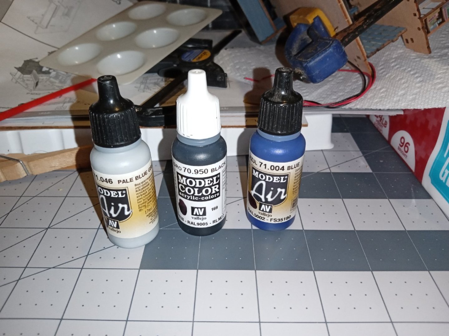
The proportions I used were:
10 Parts gray
2 parts black
2 parts blue
For the little I needed I just mixed them in the paint tray. The Vallejo bottles are designed so that it is easy to dispense them a drop at a time, and that is how I measured them out., using 10 drops of the gray to start with. If I had needed a large batch, I have several empty bottles the same form factor as the Vallejo ones, I bought on line. I bought these a few years ago, and have no idea where I found them. I think a search for 17mL paint bottles would turn them up.
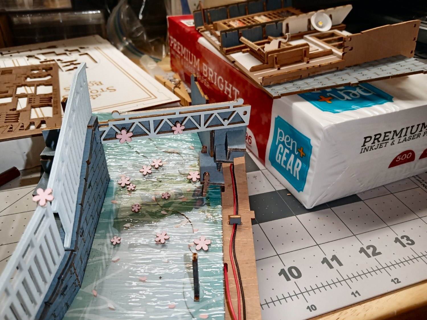
Here is a picture of the painted edge.
I went back and painted as many of the masonry edges as I could reach, at this late stage of construction. The Vallejo paints had no trouble going over the colored pencil marked surfaces.
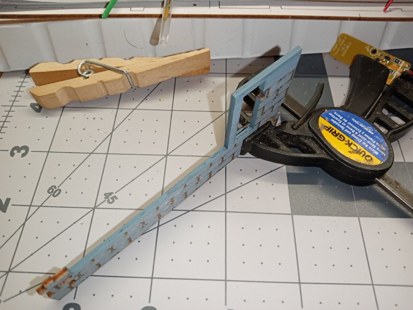
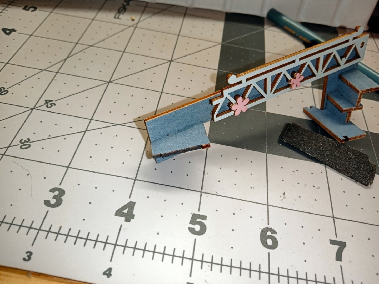
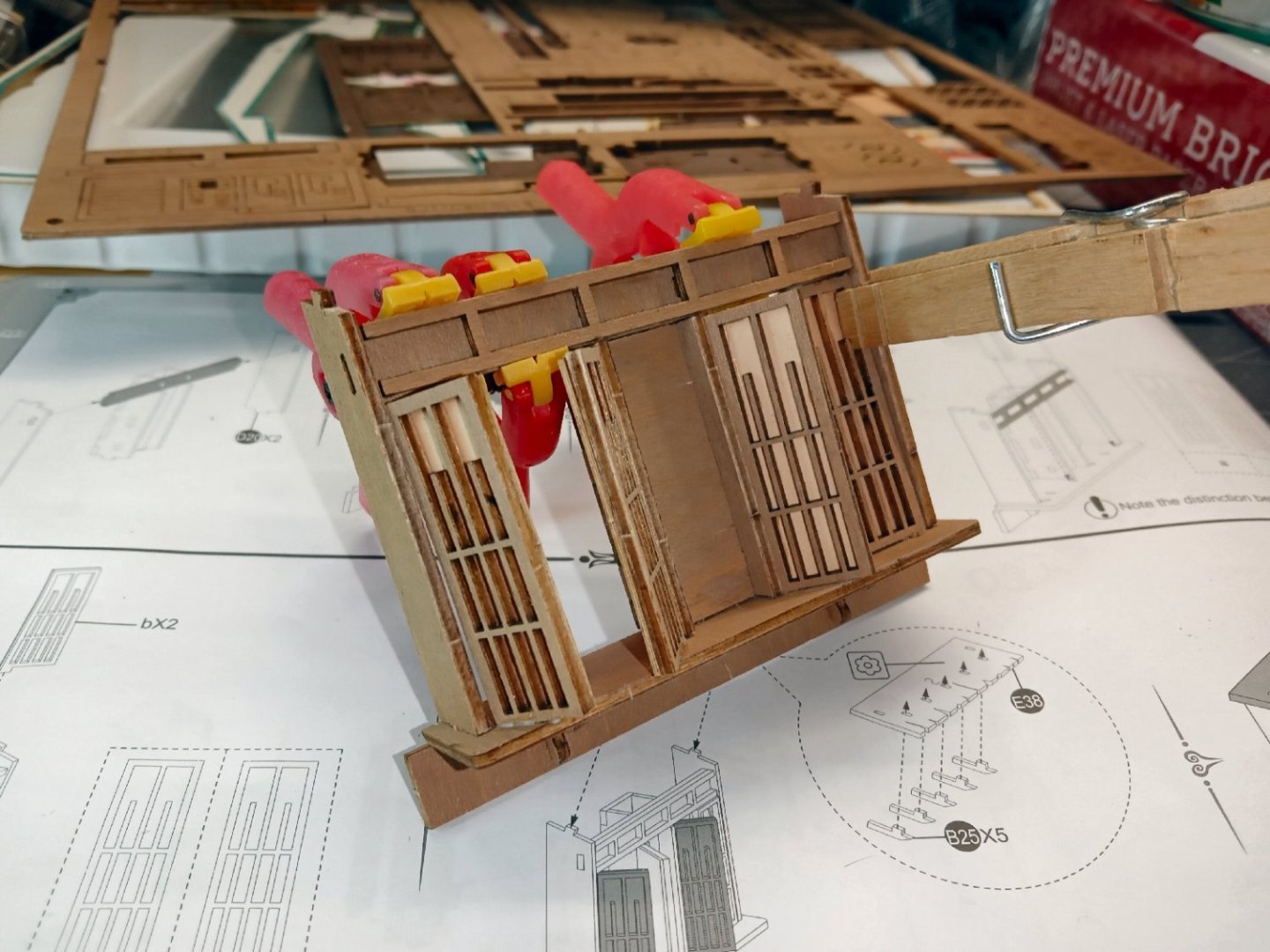
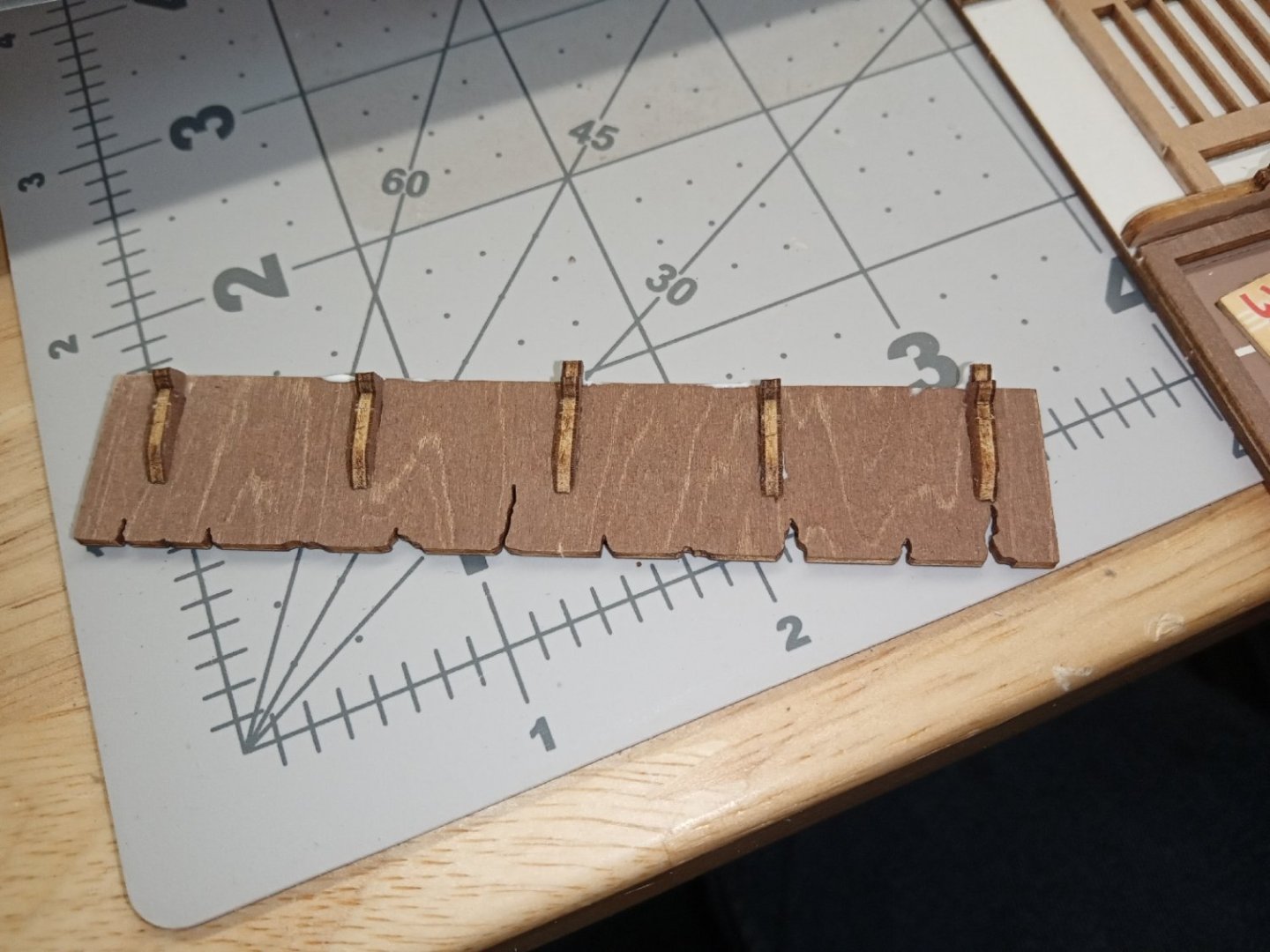
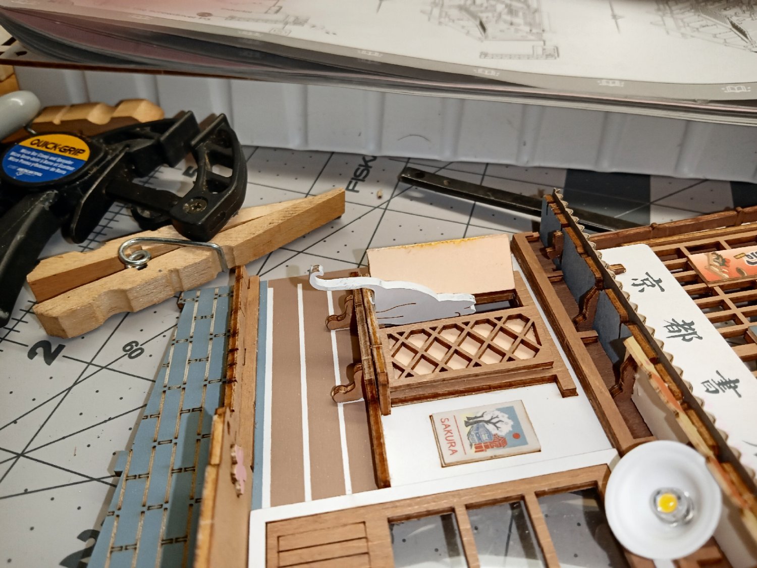
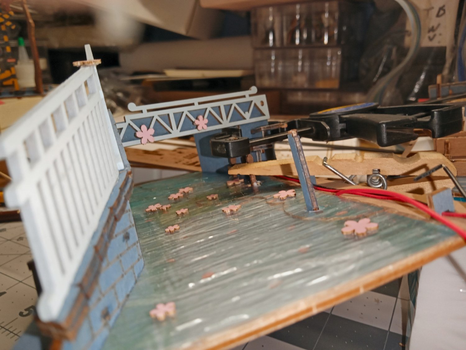
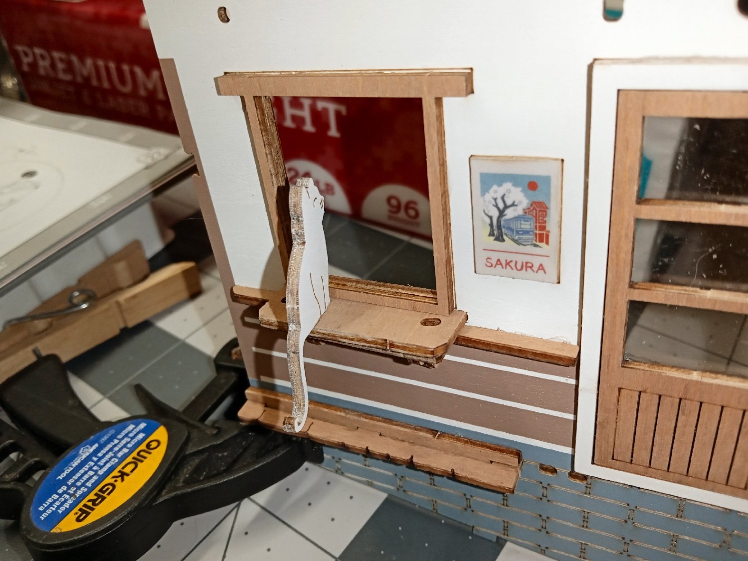
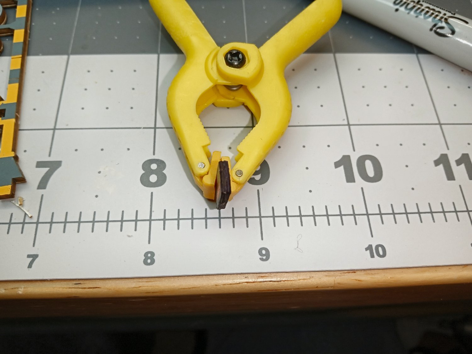
The next step was to reattach the gate arm. There is not a whole lot of contact area, and the mirror will be behind the tram, so I don’t want to add a rear brace, in case it would show. I came up with this setup to hold the arm while a glob of glue dries on the joint. I used extra glue here, counting on it drying clear and sitting at the back of the diorama, to hide it. I wanted the extra to reinforce the joint. The clothes pin on the left is being used as a wedge to position the clamped tip of the arm.

Here is the arm the next day. I may pull it a little forward and glue it to the back of the railing. I don’t know how well the glue will support the arm as time goes on. Yes, the trolley pole also broke off, I glued it back on today.
- king derelict, mtaylor, Egilman and 4 others
-
7
-
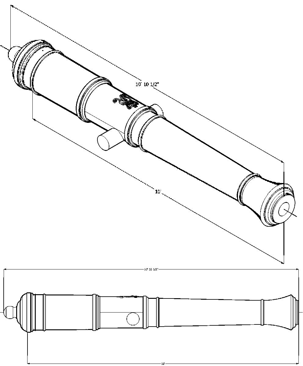
The Bogard Cannons have the following sizes, at on the drawing I have:
4 Pounders:
84"
90"
6 Pounders:
90"
96"
102"
9 Pounders:
96"
102"
108"
12 Pounders:
102"
108"
120"
18 Pounders:
102"
108"
120"
24 Pounders:
110" (108"?)
121" (120?)
32 Pounders:
108"
114"
120"
The 24 Pounders may be mis-dimensioned on my 2D drawing.
- scrubbyj427, Seventynet and mtaylor
-
3
-
-
Part_015
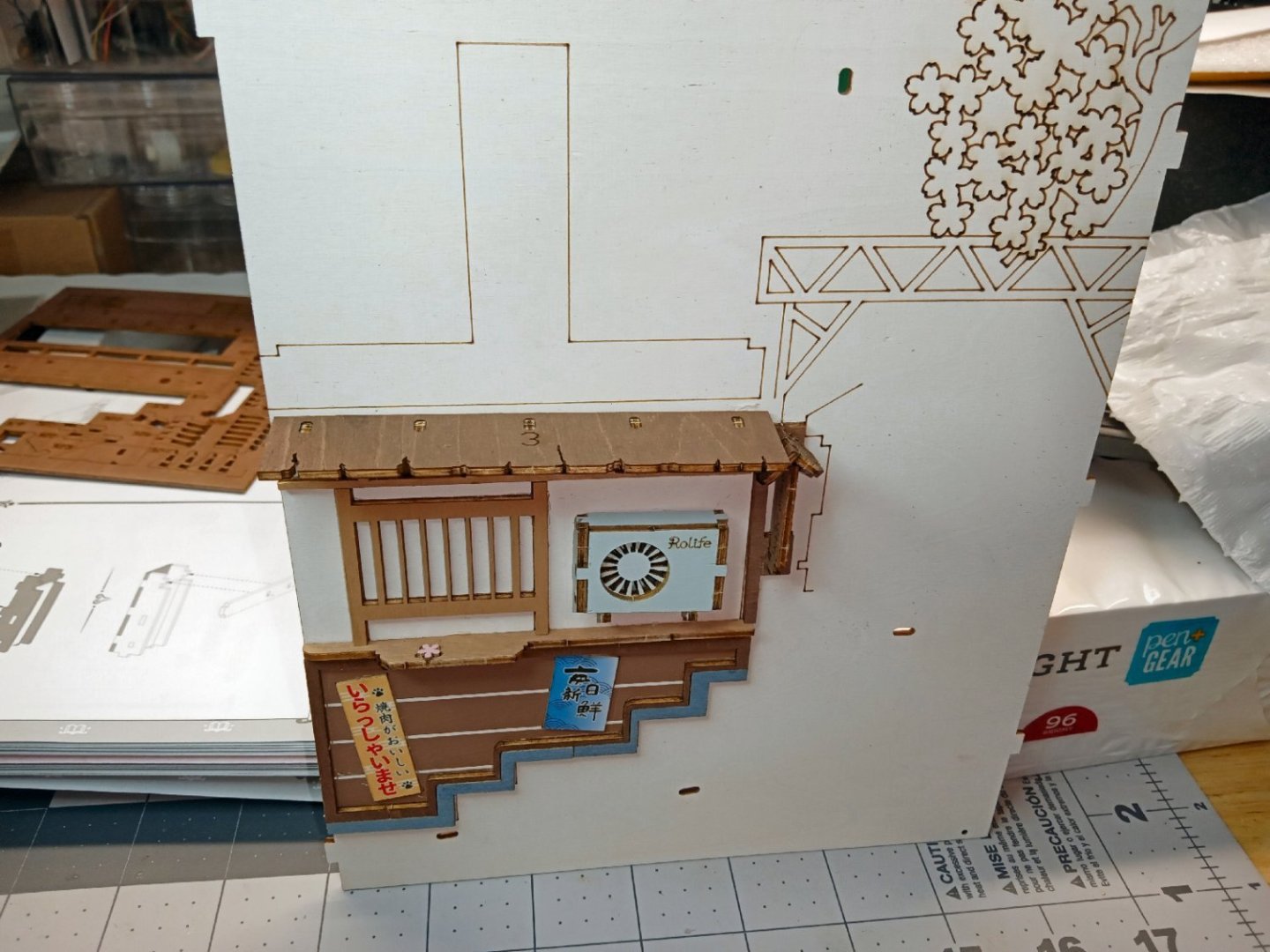
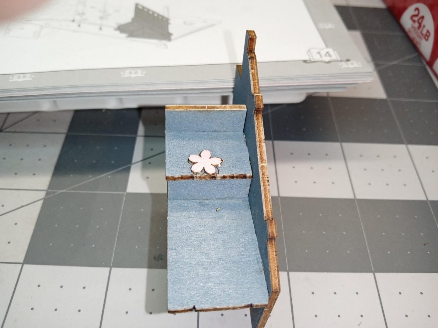
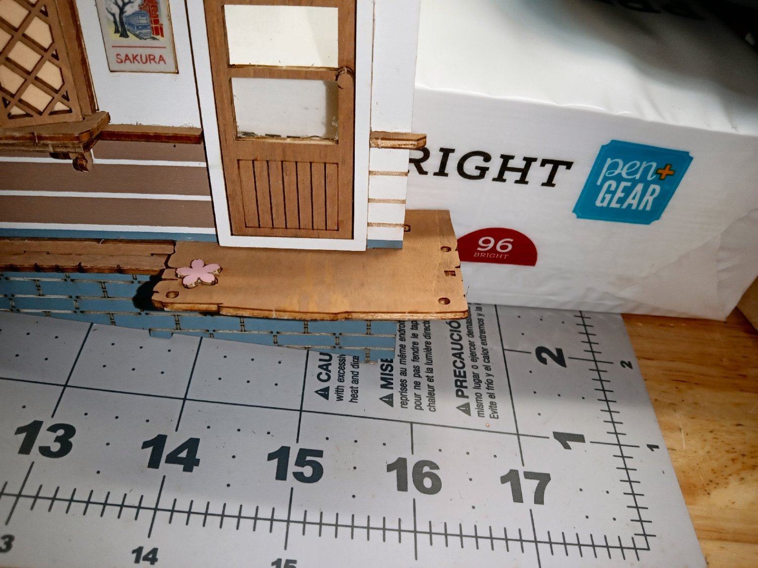
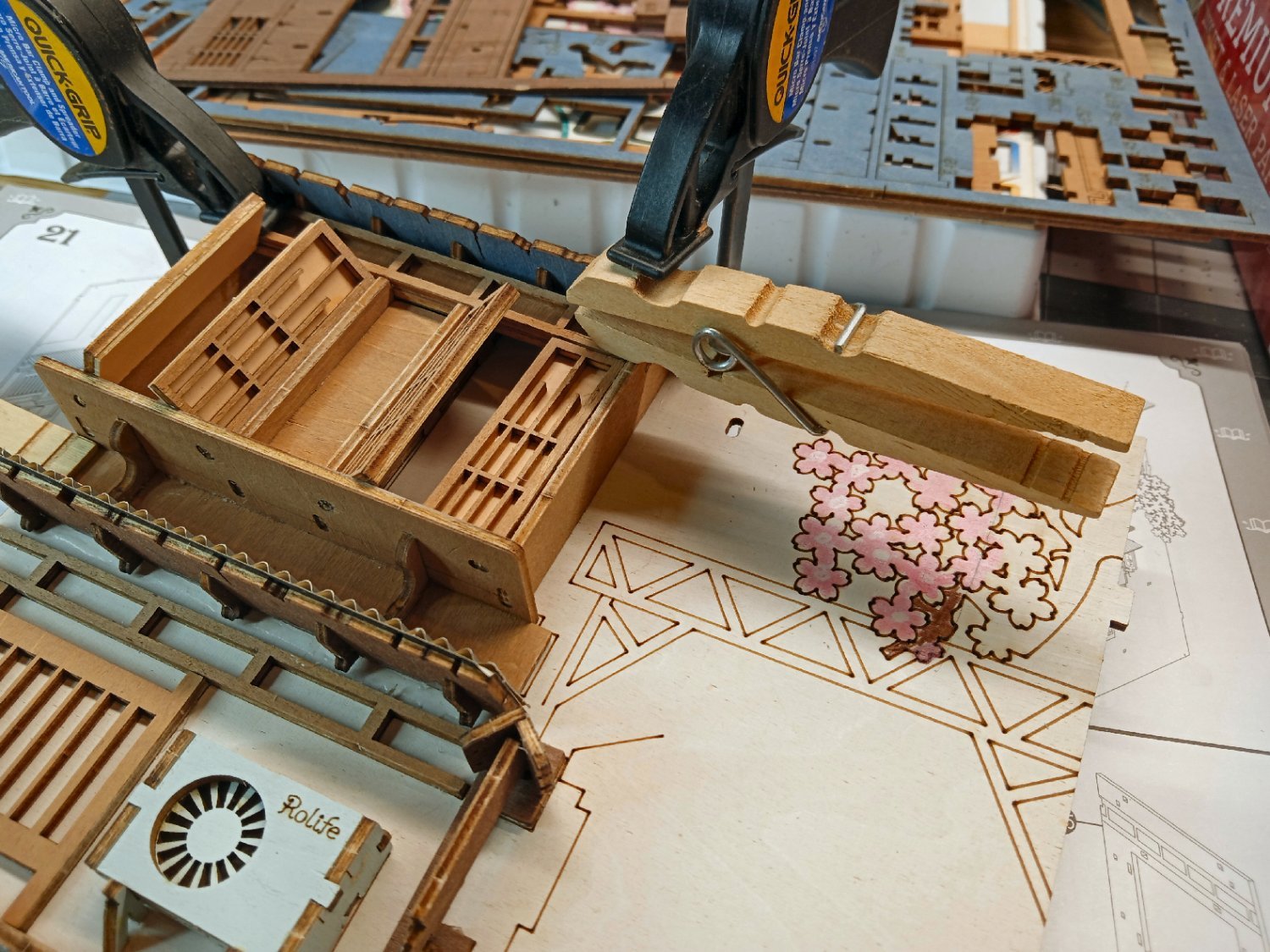
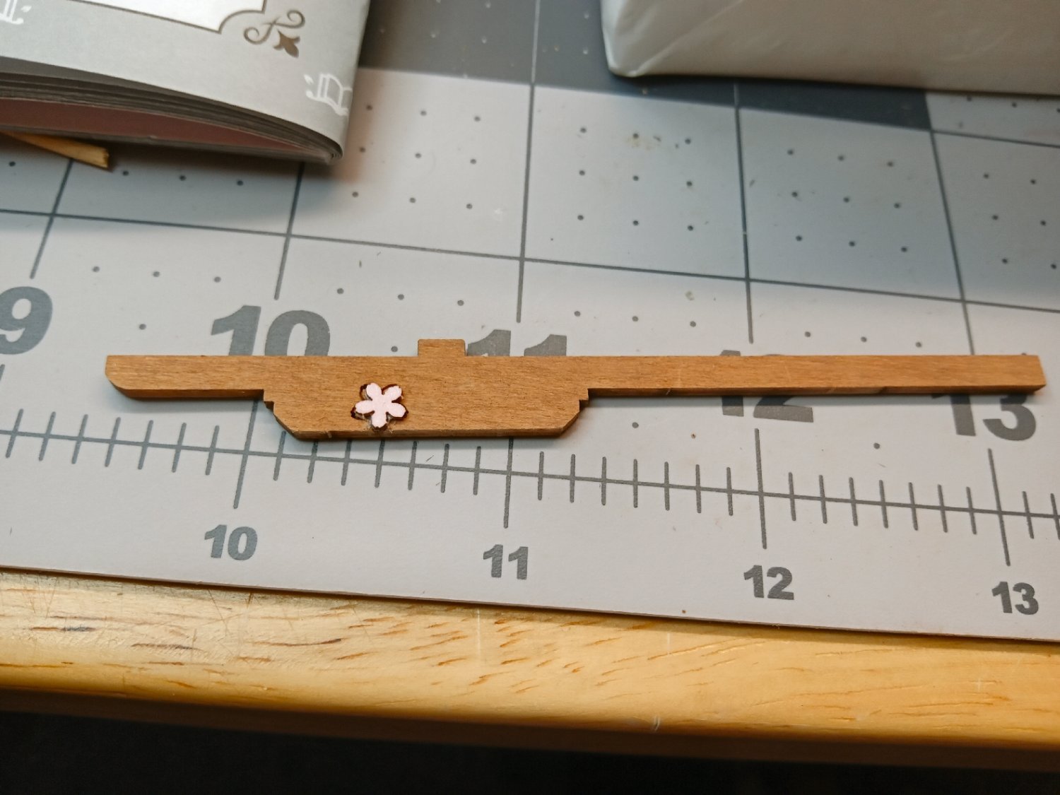
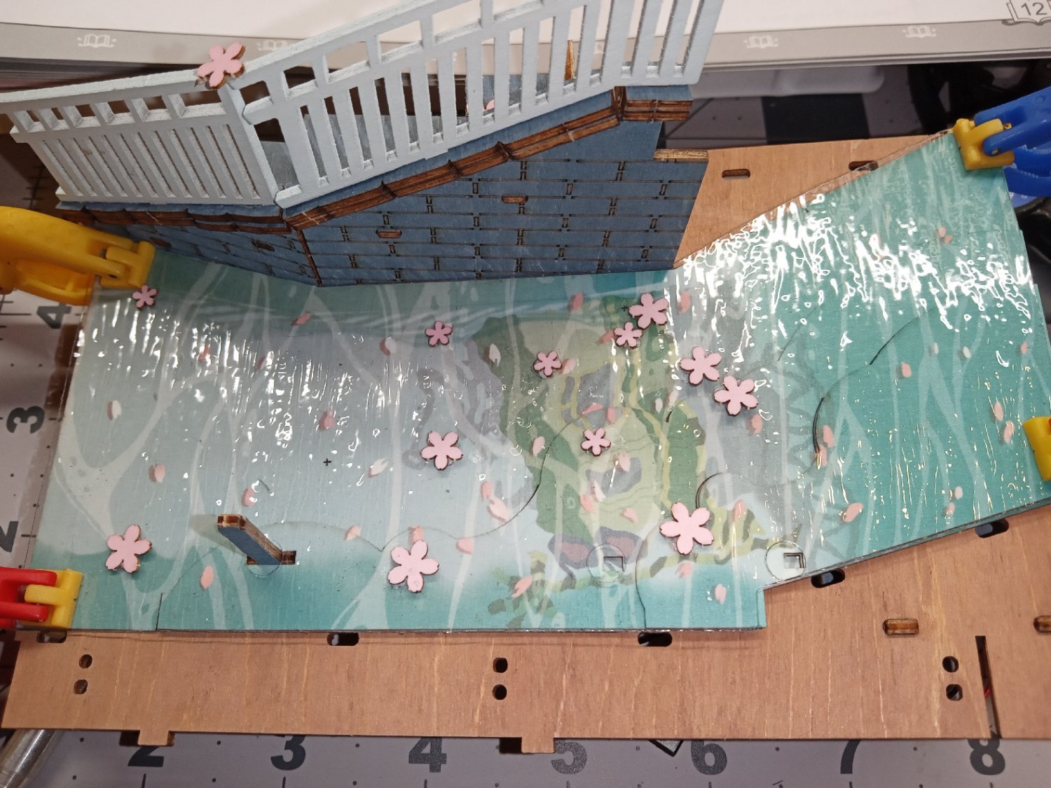
I returned to the area of the door, to continue assembly. A porch floor, with cherry blossom, is installed.

This store has a book shelf display window, that is glued to the back of the wall assembly.

This is followed by a print sheet of books.

On the outside. of the shelf, there is supposed to be a window pane. Unfortunately, in order to protect the acetate pieces, I stored them in a “Safe Place”. Once I find that place again, I will install it!
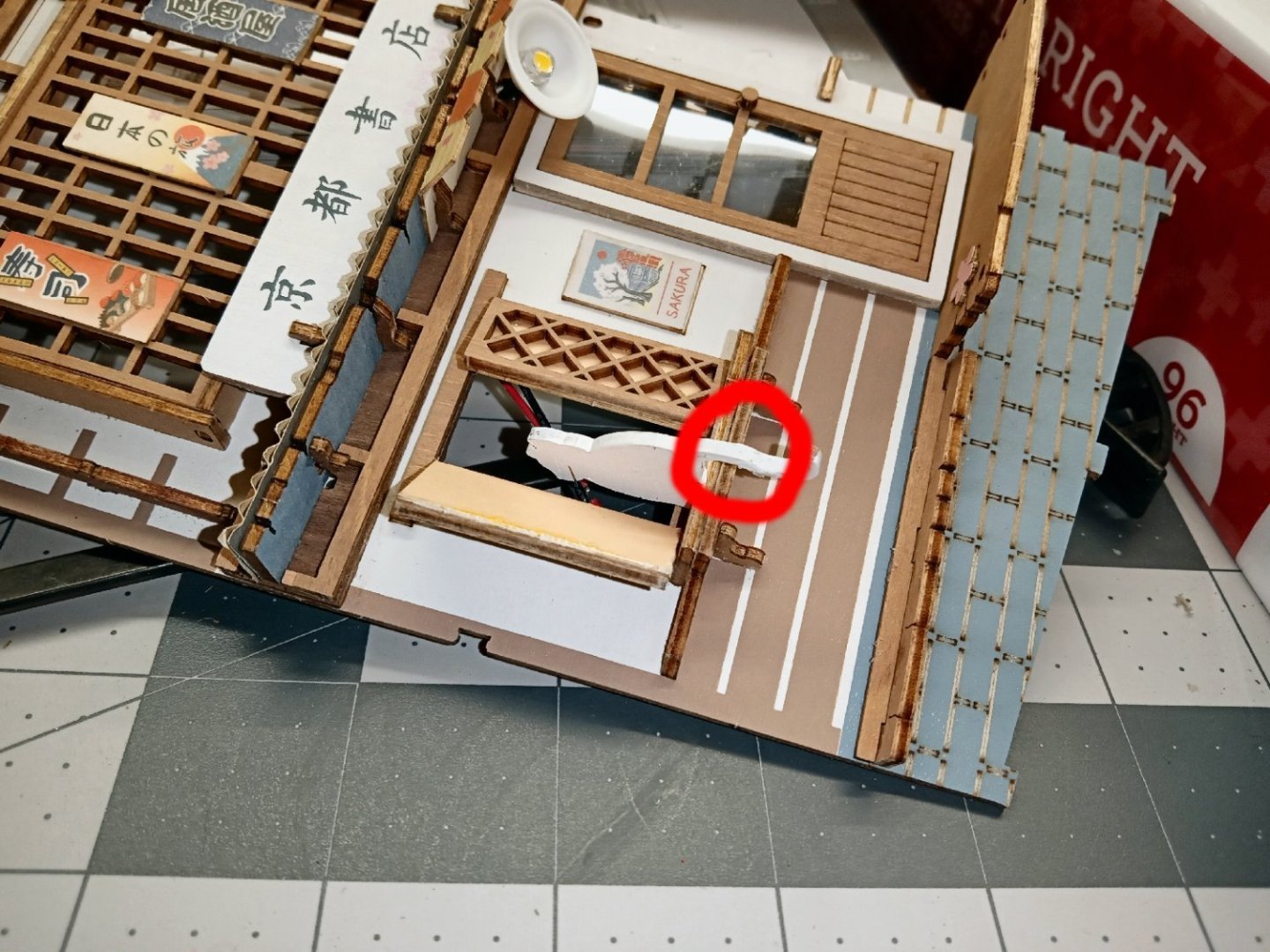
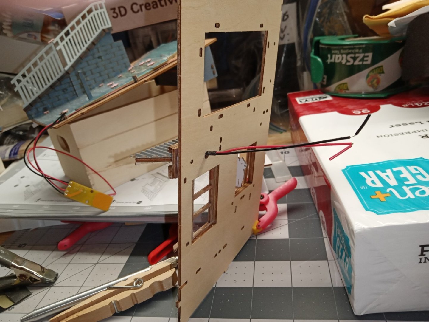
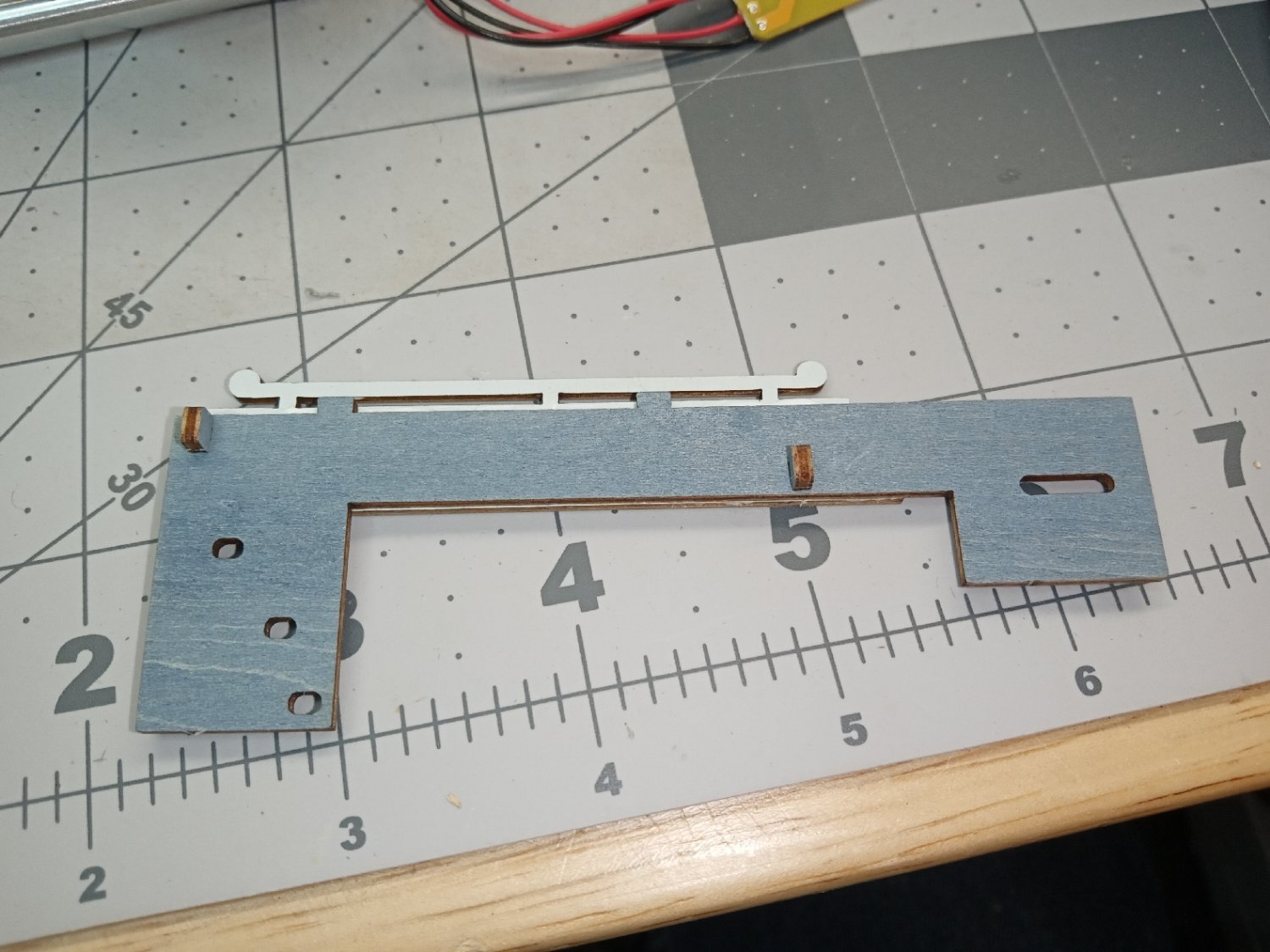
Here is where the poor cat lost its’ tail! The picture below shows the back of the wall and the wood staple for the LED wires.
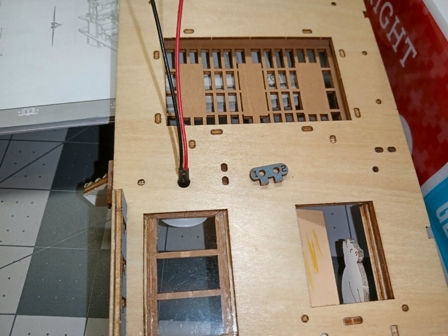
Here it is after I finally got it installed.

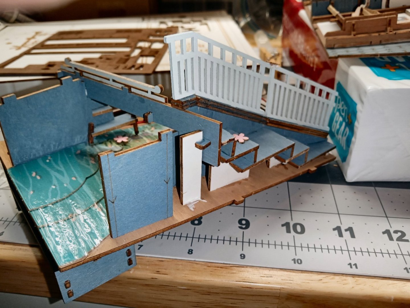
A few posts back I said I was going to wait to install the bridge, until later, so I could have a little wiggle room to install the side walls. I might as well have done it then! The next section is building the bridge, and the parts lock it in so firmly, that there is no adjustment, even with none of the parts glued in!
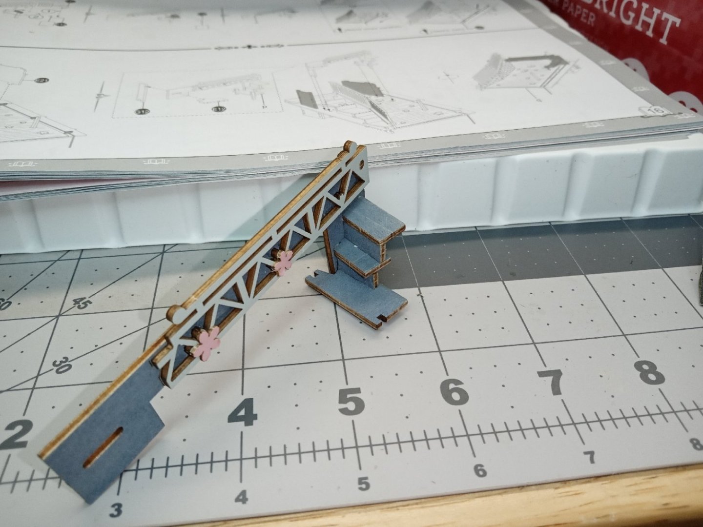
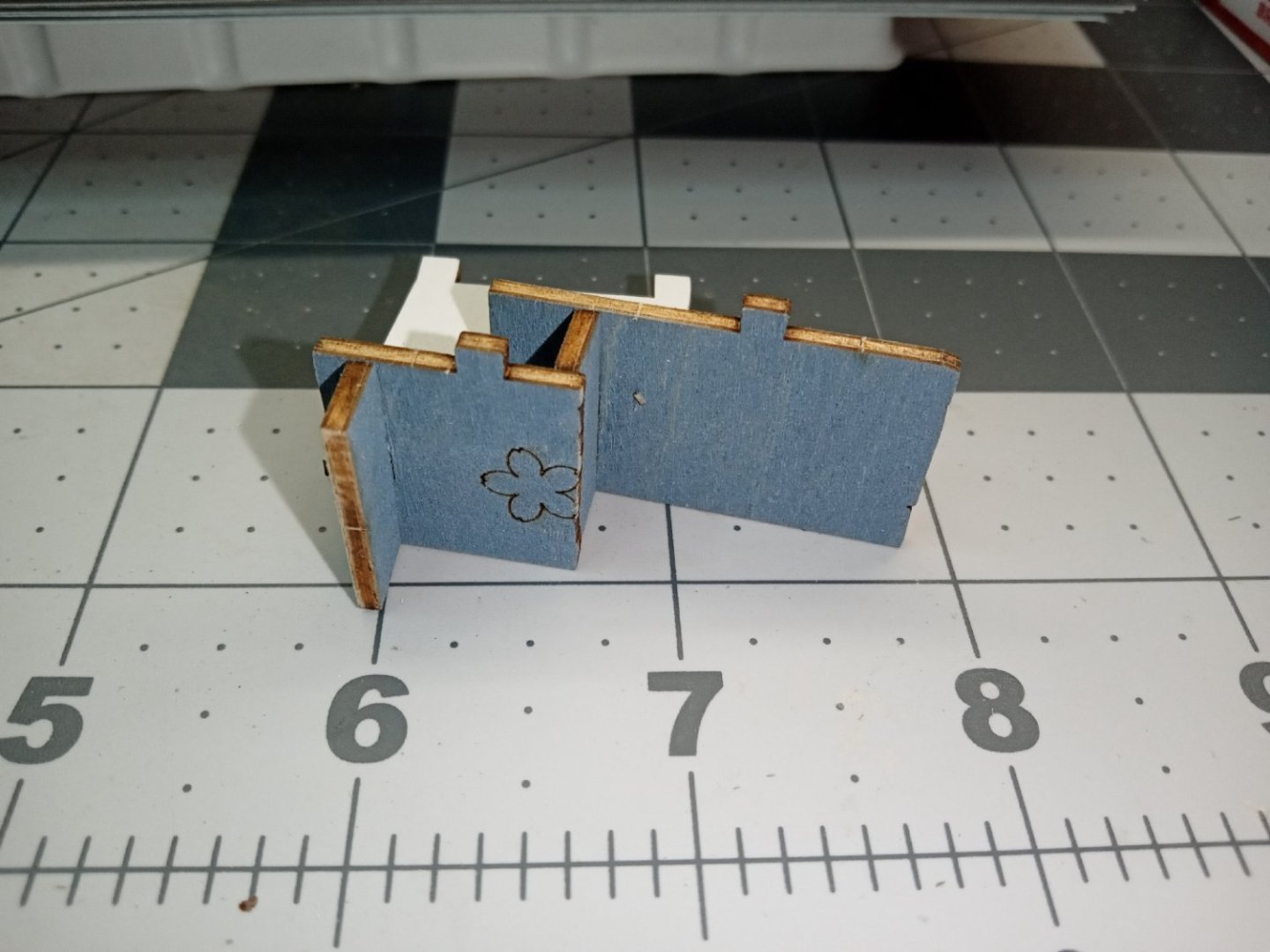
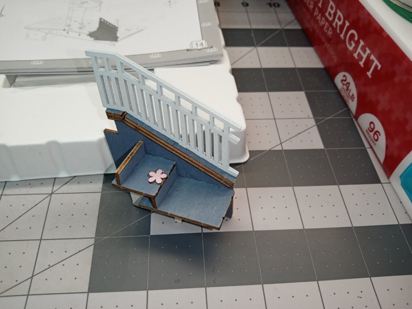
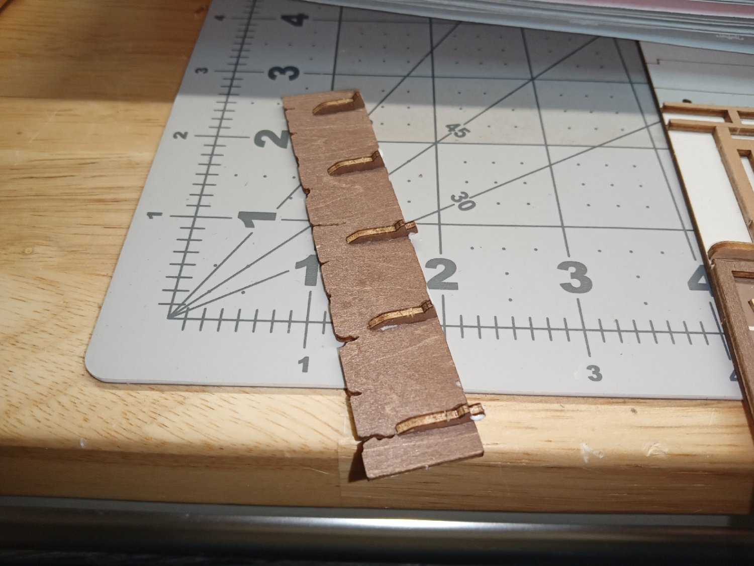
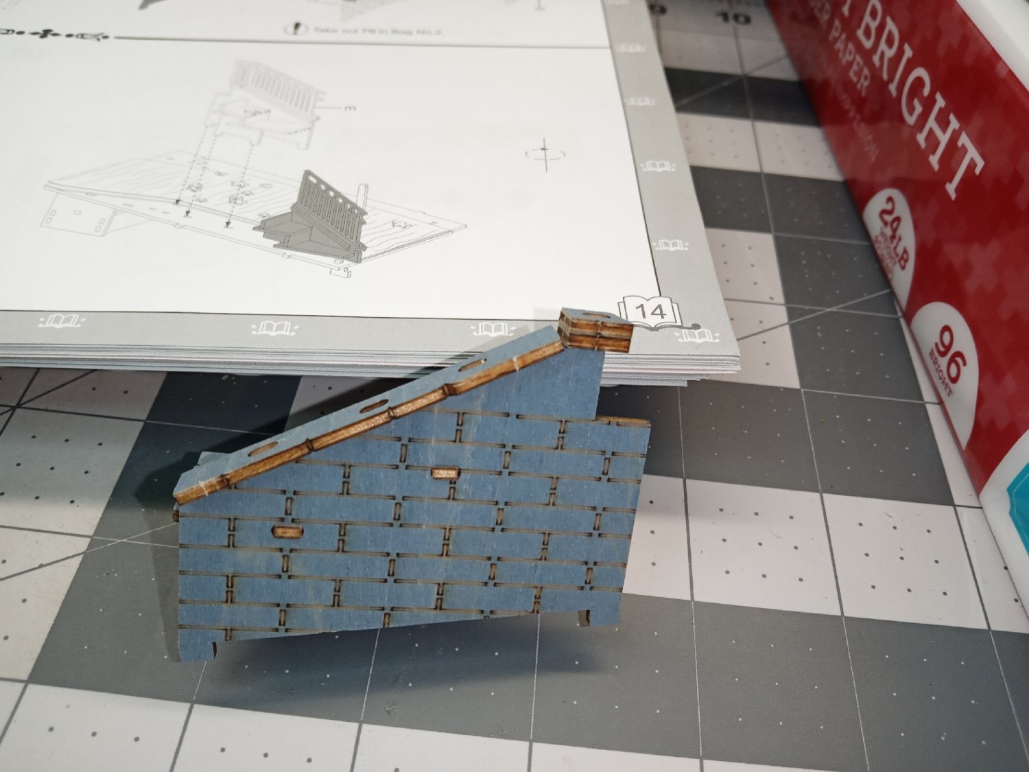
Below is a photo of the two bridge piers that go in first. None of the following parts were glued in until the whole bridge was fitted. When that was done, I ran beads of glue at the joints, to fix them in place. The pier on the left has marking to indicate the correct orientation.

Here they are installed, without glue.
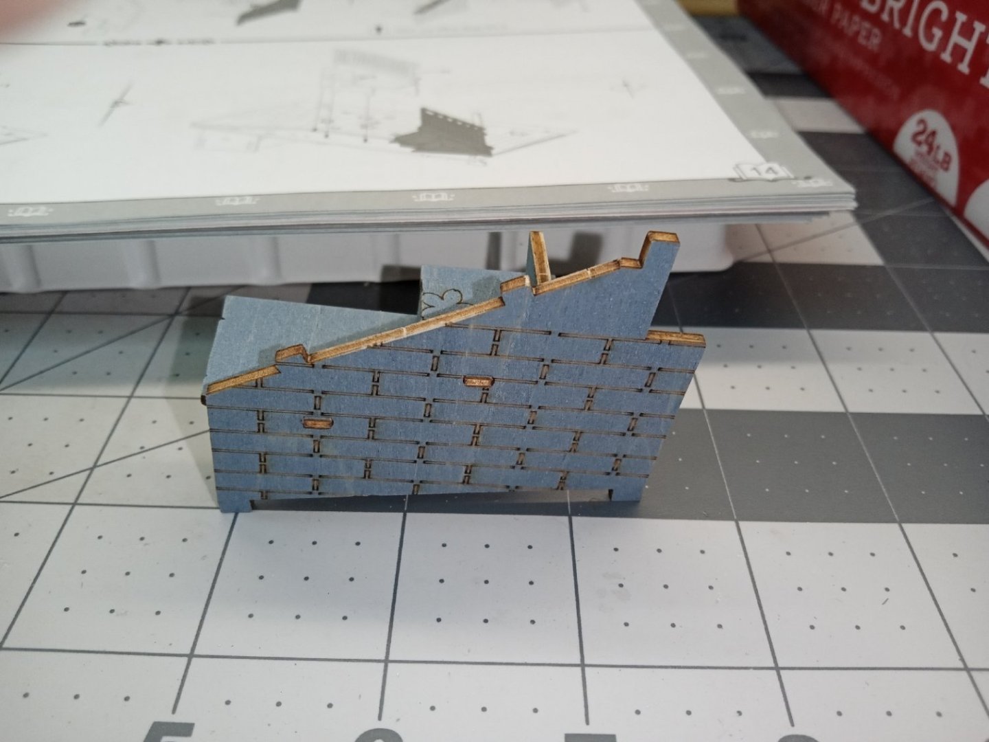
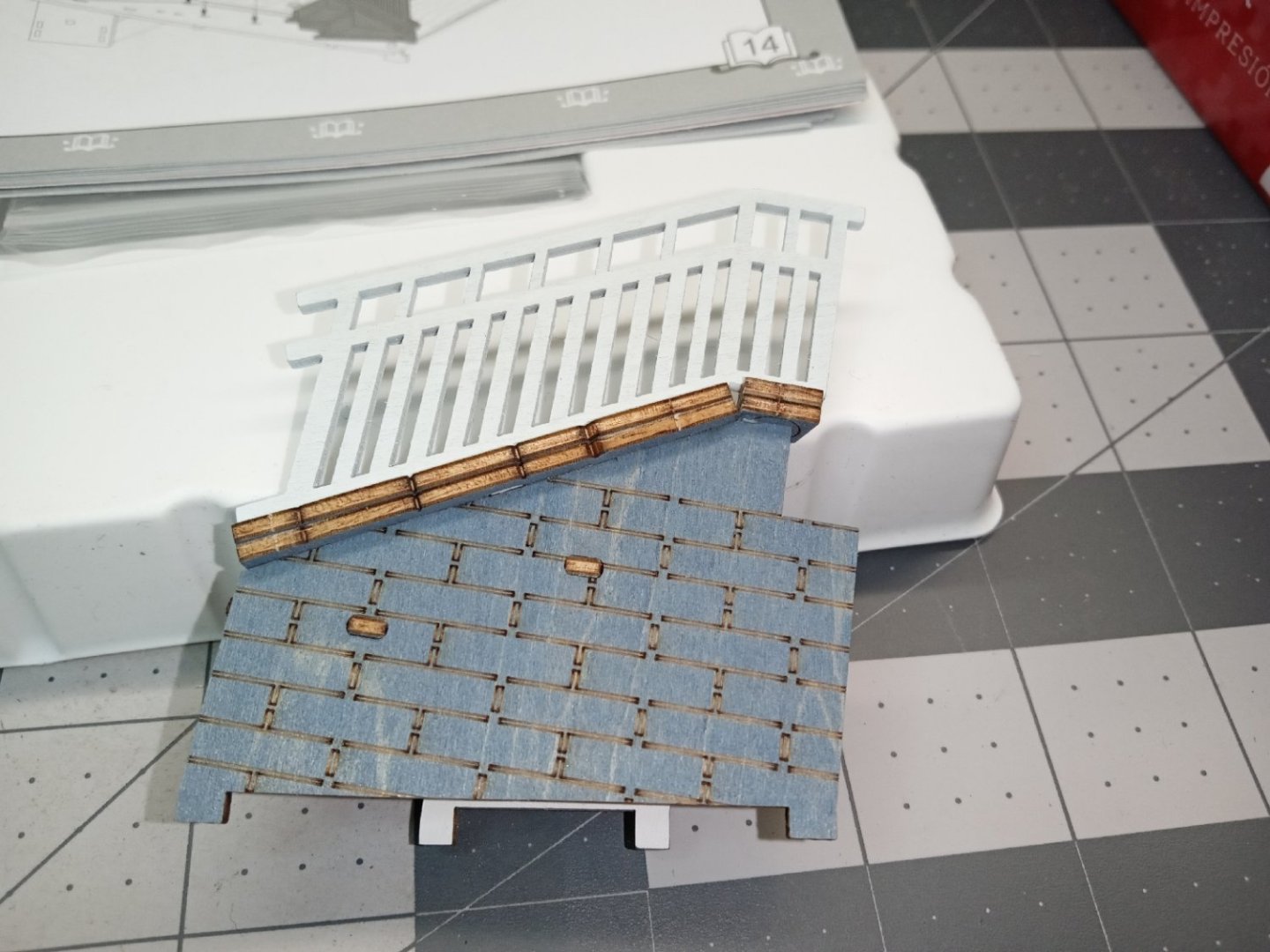
There is a step to attach to the left side of the bridge beam, this forms the top step of the staircase on the retaining wall. I used the slate pencil to color the edges of this step, as well as the steps on the right side of the bridge. I glued this piece.
The left-hand support was fitted, next. Once again, no glue at this point.

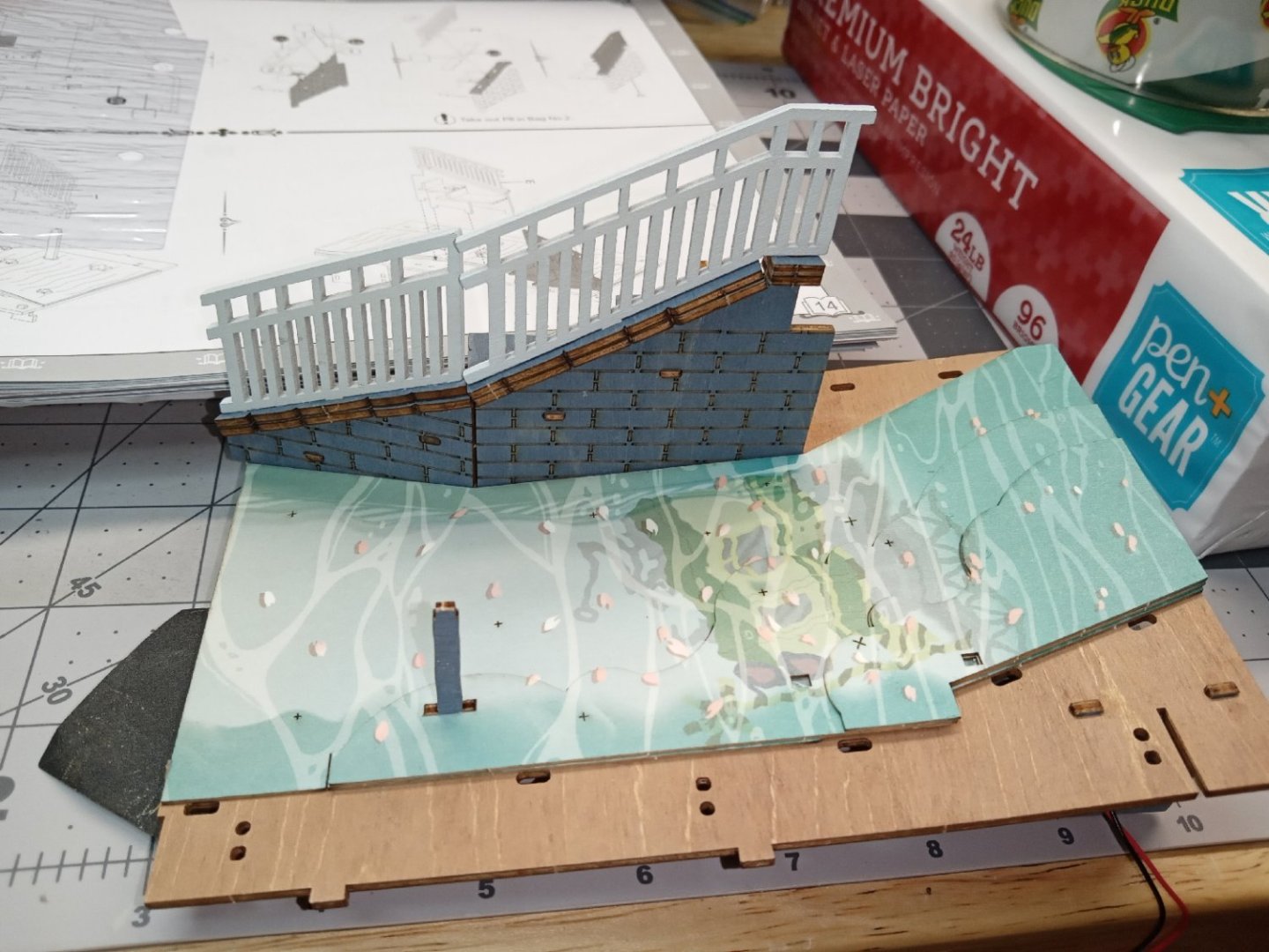
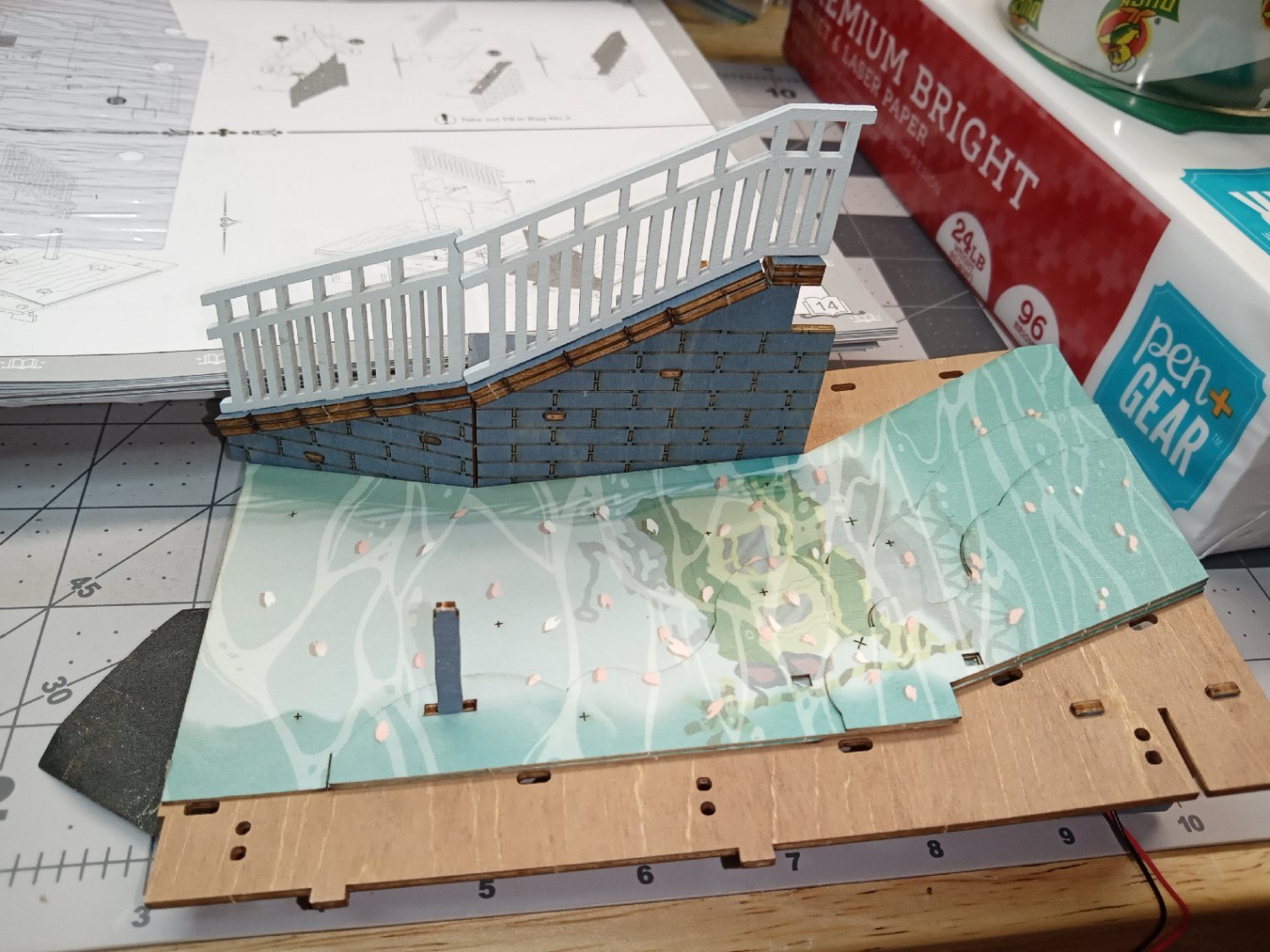
The bridge has been fitted, and glue applied to the joints.
It was at this point I remembered the two piers that hold up the lowest step on the right side! Much fiddling and bad words got the pieces in place!

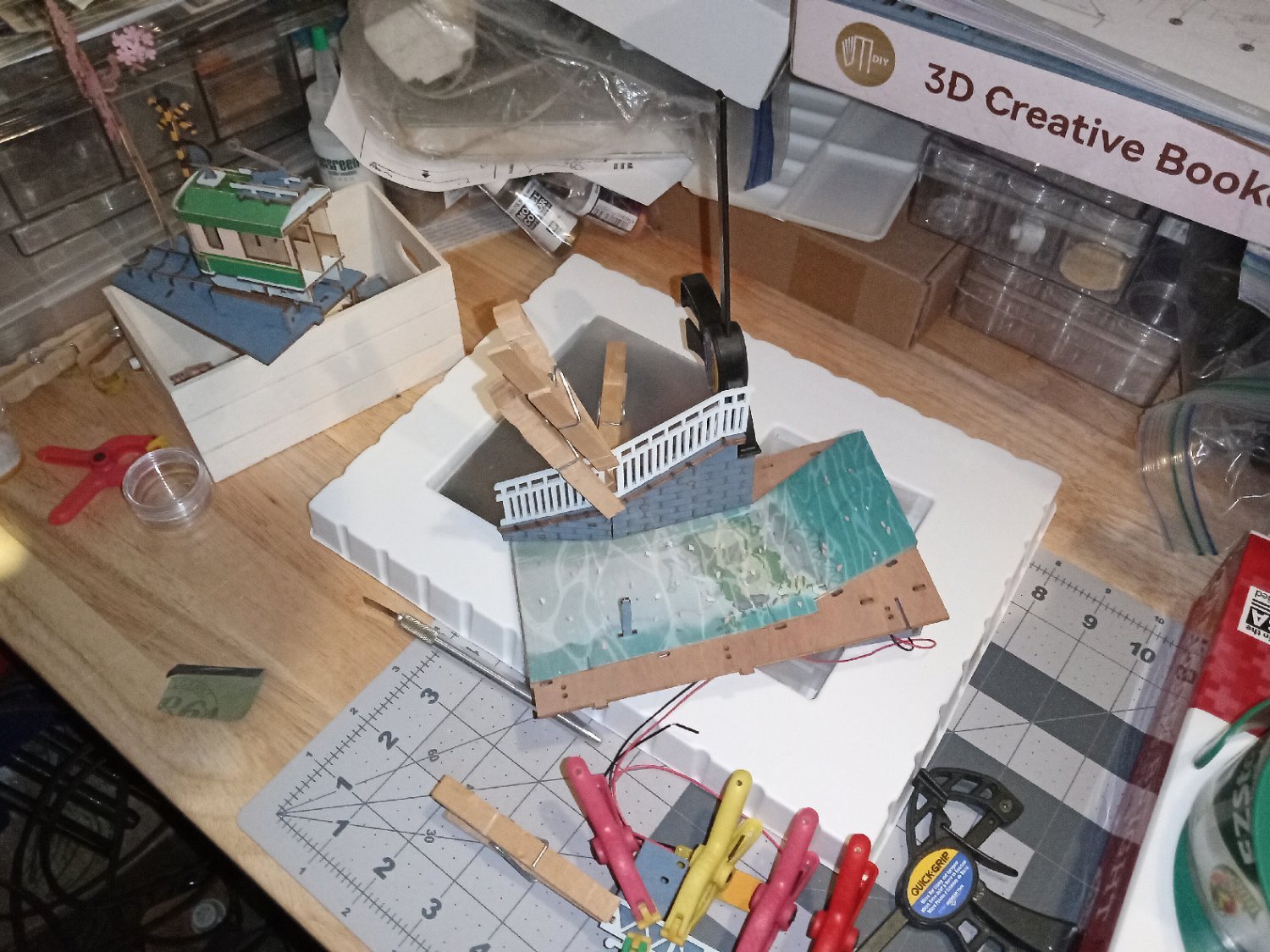
I had to do some clamping to hold the bridge to the support, and hold the lower step down while the glue attaching the bottom of the piers to the stream bed dried.

Next, I clamped the top step in place so it lined up with the riser on the retaining wall.
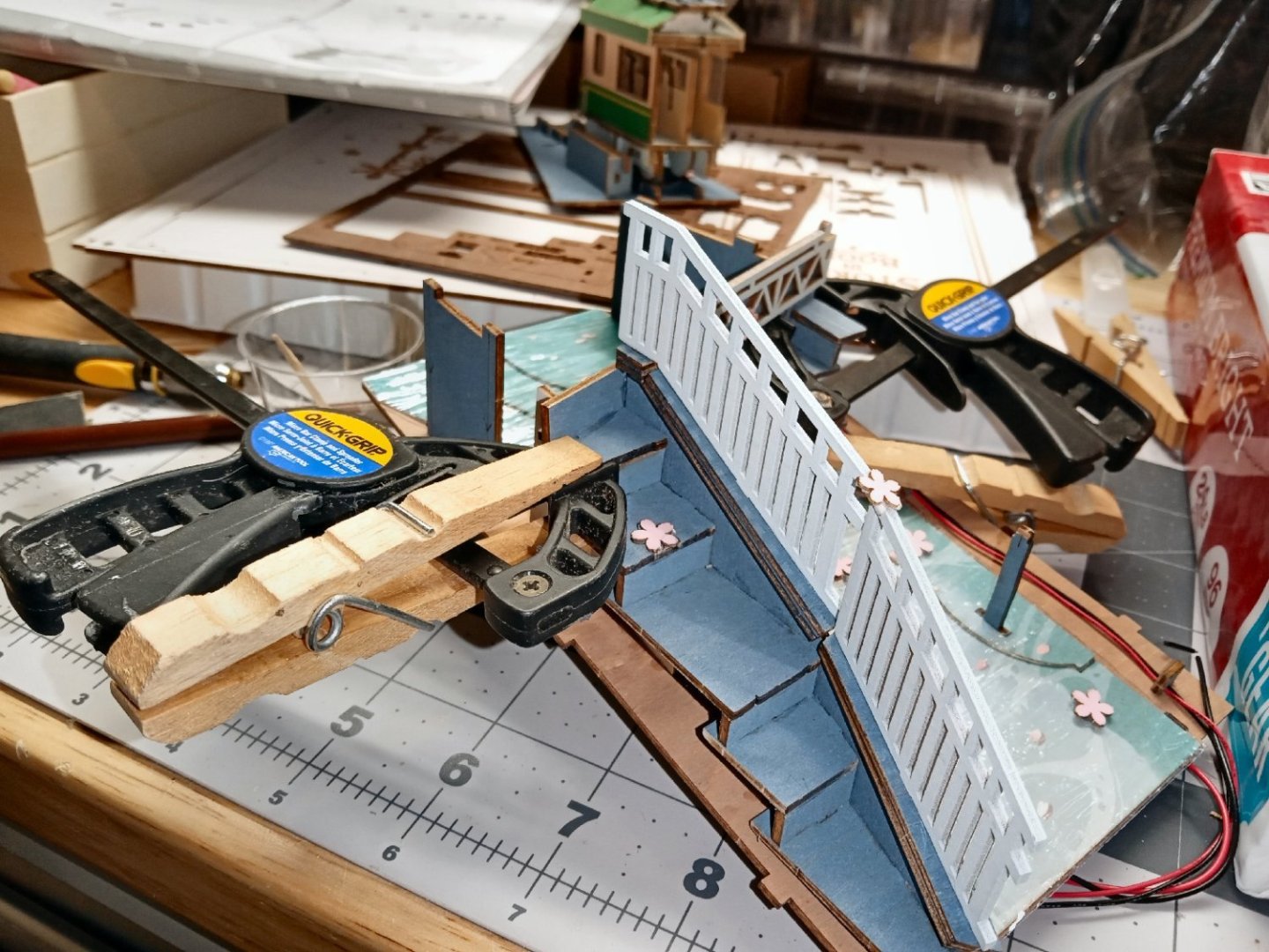
This was then left to dry.
-
Part_014
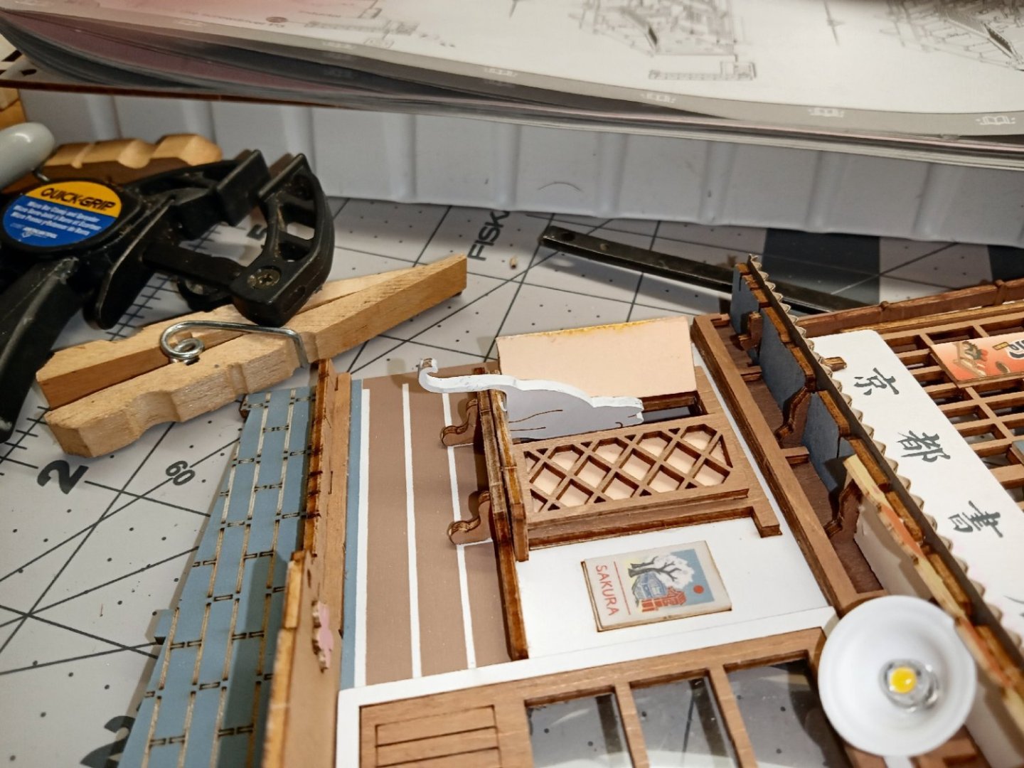
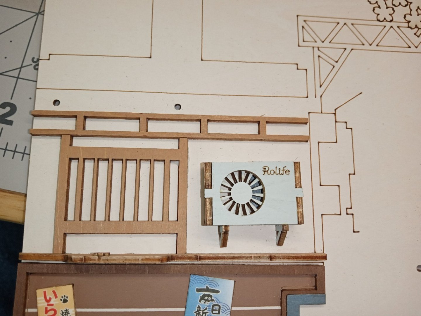
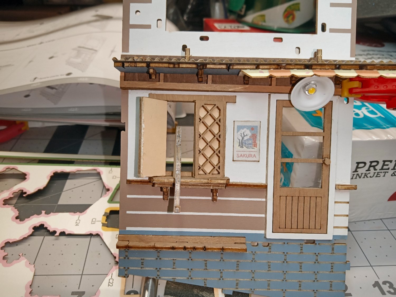
The top layer of the window sill and the window frame went on next, as well as the cat figure. (Yes, the Japanese are typically Cat Crazy, I really like that about them). As it will be detailed later, I should have waited until the wall was attached to the base to install the cat. Later I managed to break the tail, while running the wiring for the LED lamp. I used a white pencil to color the edge of the cat figure. Paint would have been a better choice.

The windows were glued in, and an additional bead run down the hinge area at the back

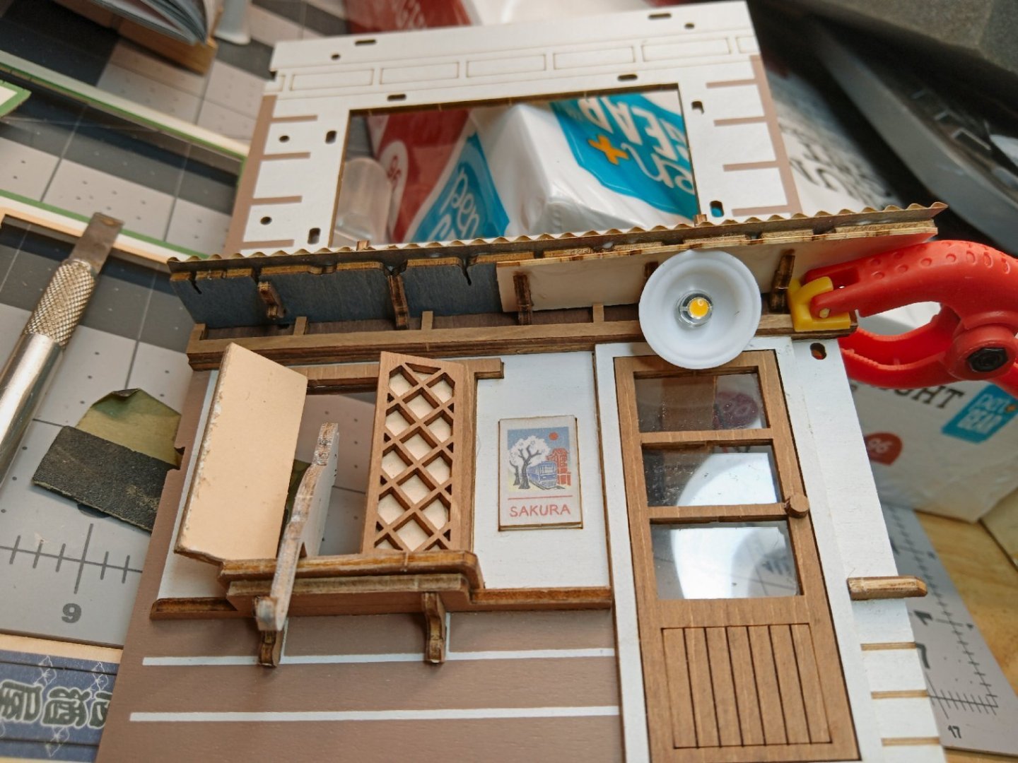

This picture shows a closer view of the LED light and shade. Also, at some point previously, I glued on the door knob.

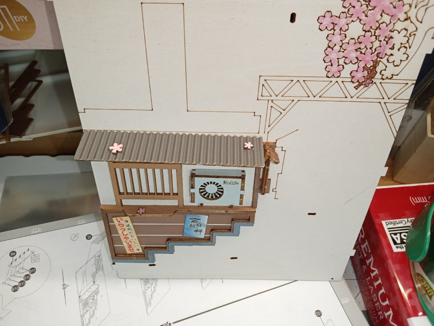
Brackets for a sign, and trim pieces are attached above the first-floor roof. I think these represent a gutter that the future drain pipe will feed.

A picture of the wall from what will be the back of the diorama.

The wiring for the LED coming out of the wall. The two holes just to the right of the wires are for a wood staple to hold, and locate the wires. These holes were overly tight, and while trying to push it in place, I broke the cat’s tail, by not watching how I was holding the wall. I left it that way, and glued it back on after I finished construction of this assembly.
Two support brackets went on next. These support the second-floor bay type window.

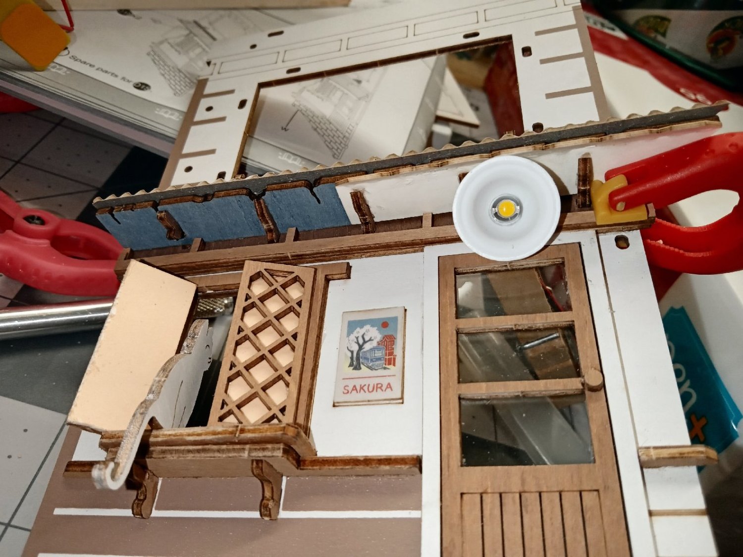
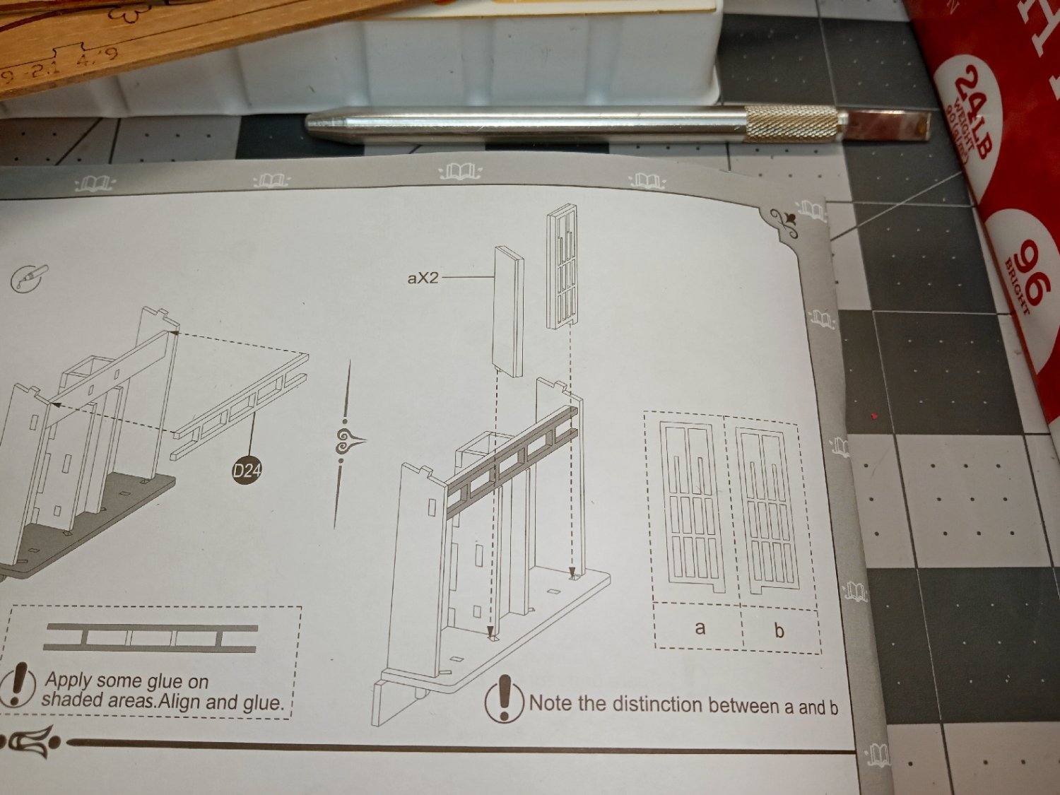
The bay window consists of an outer frame and a grill. The arrows indicate the direction to install the grill.
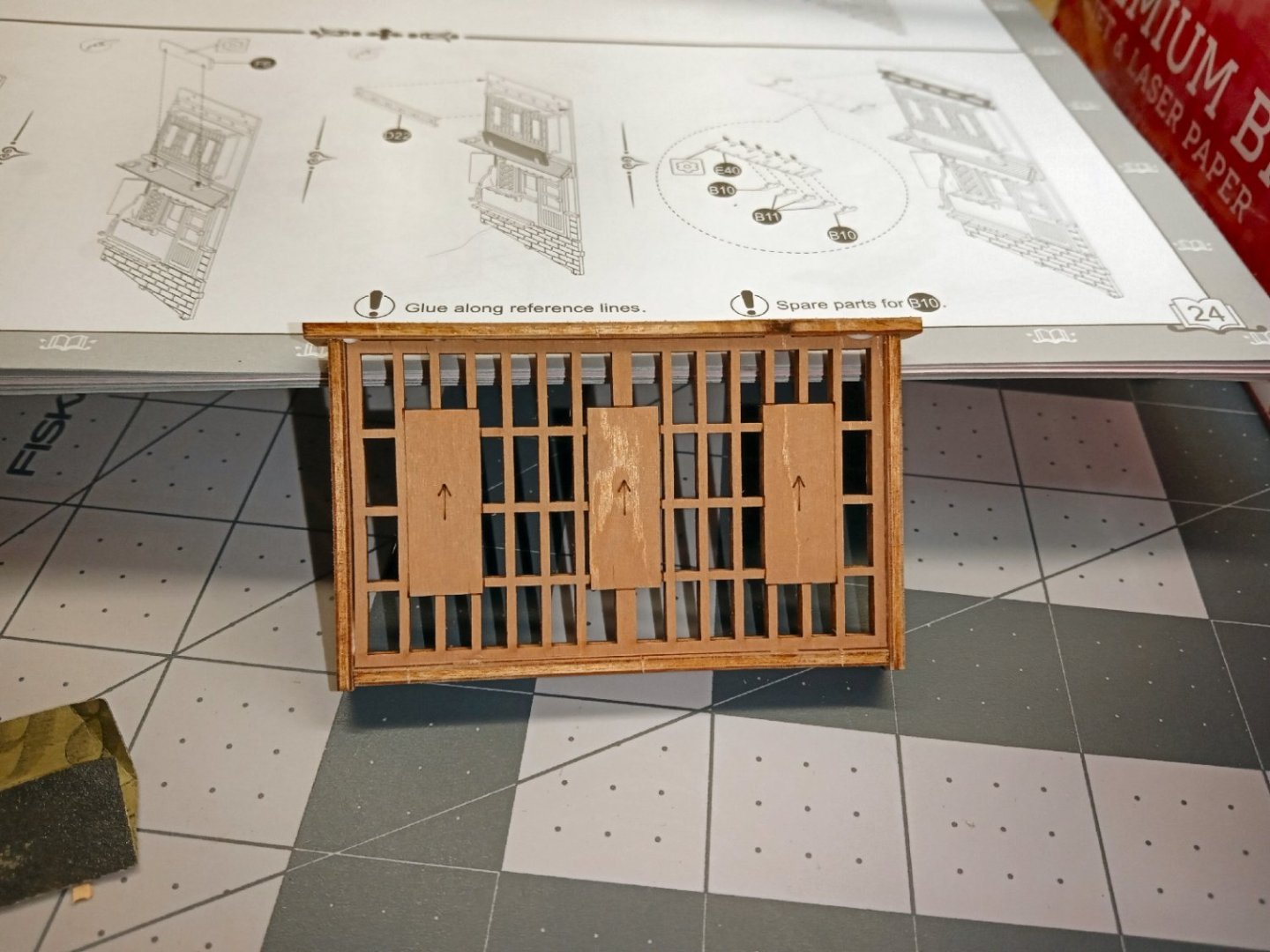
This photo shows the back of the window. The kit did not supply a tan colored window pane for this assembly. I guess there are regular winds behind the grill that are open, and thus do not show.

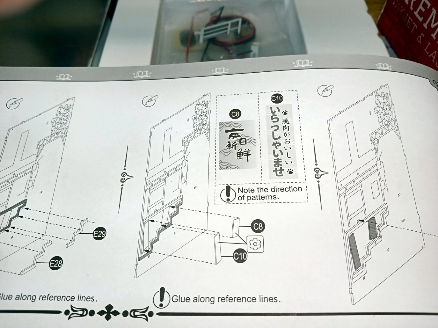
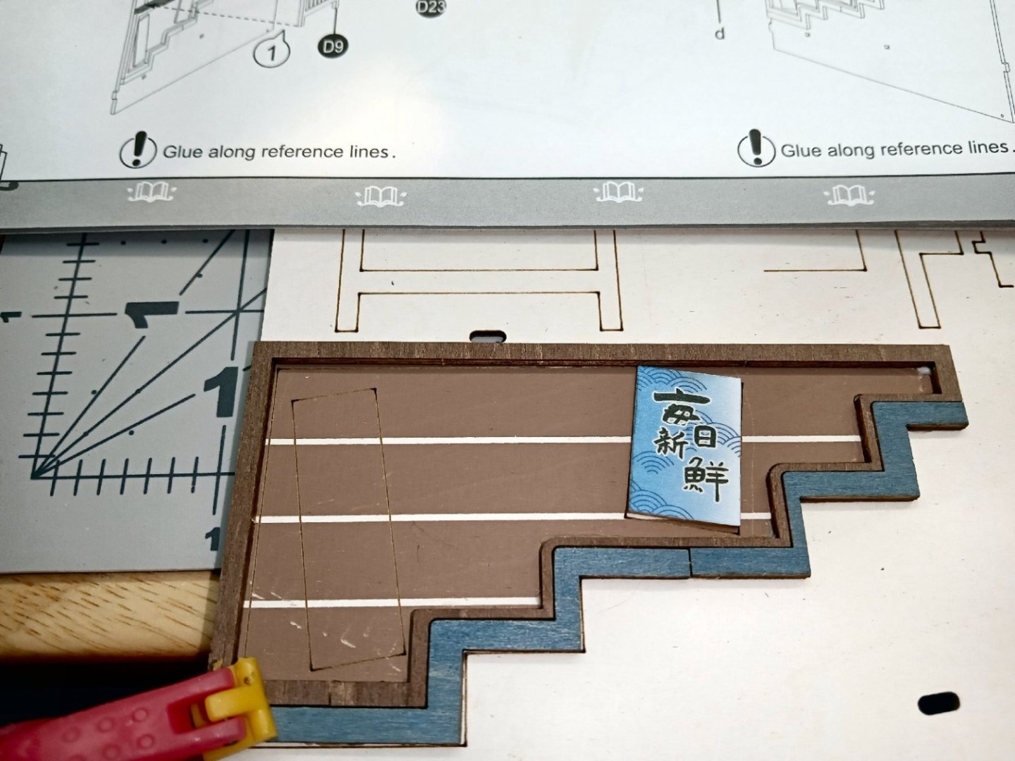
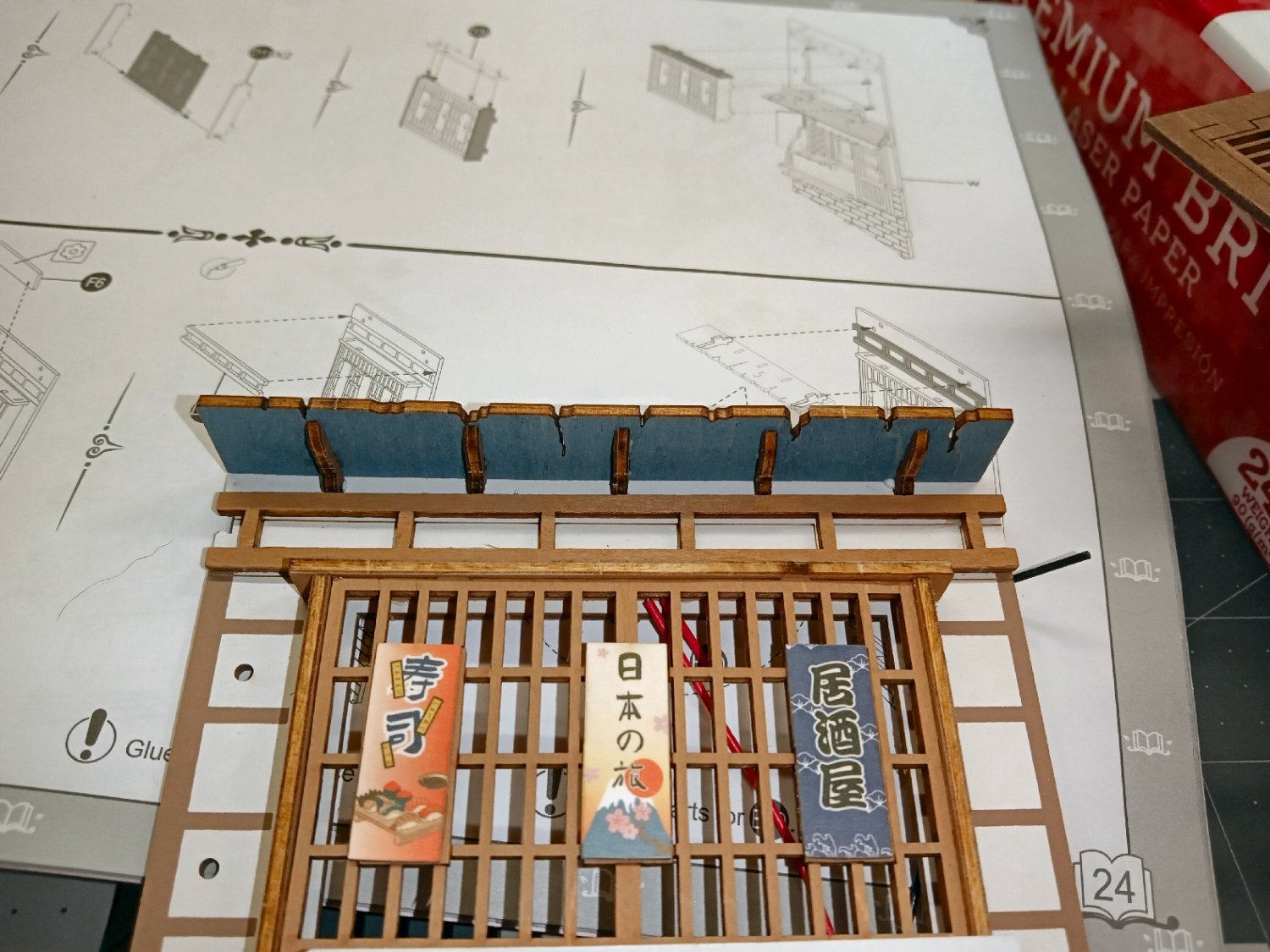
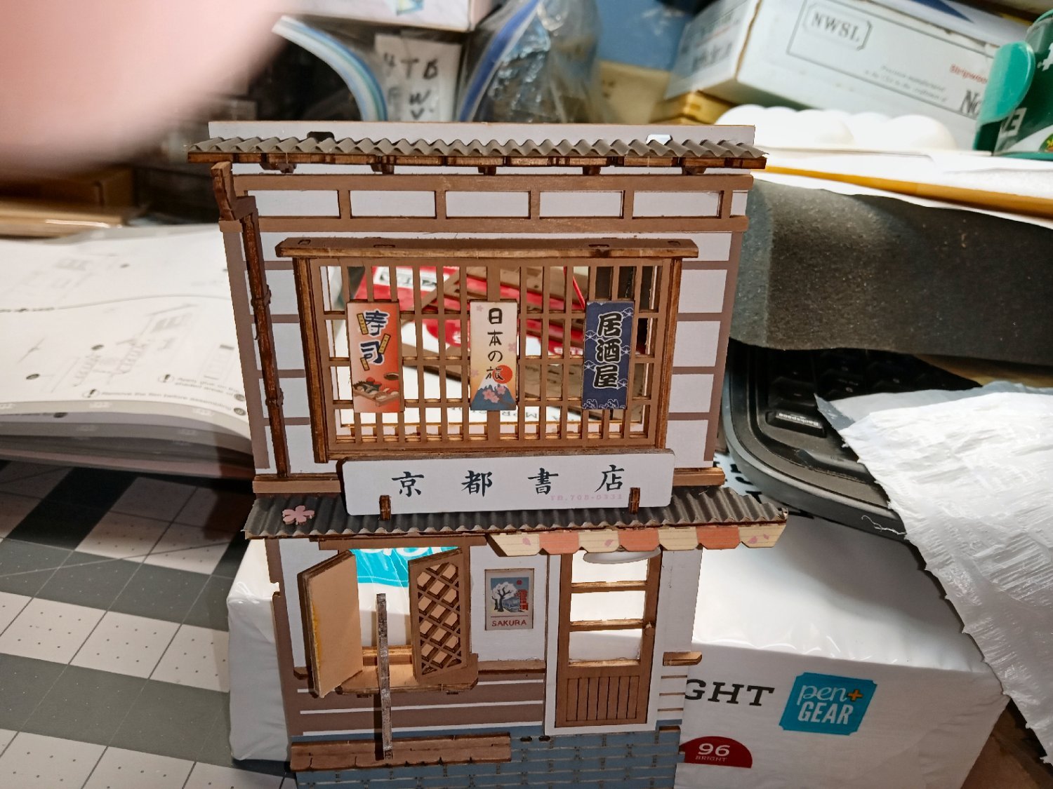
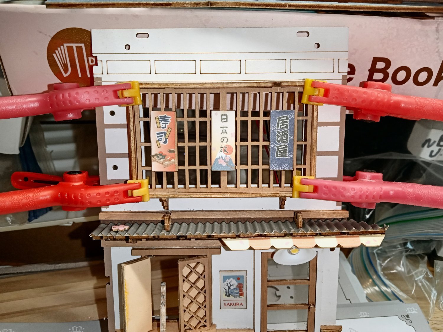
The frame was then glued and clamped in place. Three signs went on. Again, the instructions showed the correct orientation of the signs. I tried to use Google Picture Translate on the signs, but got no results.
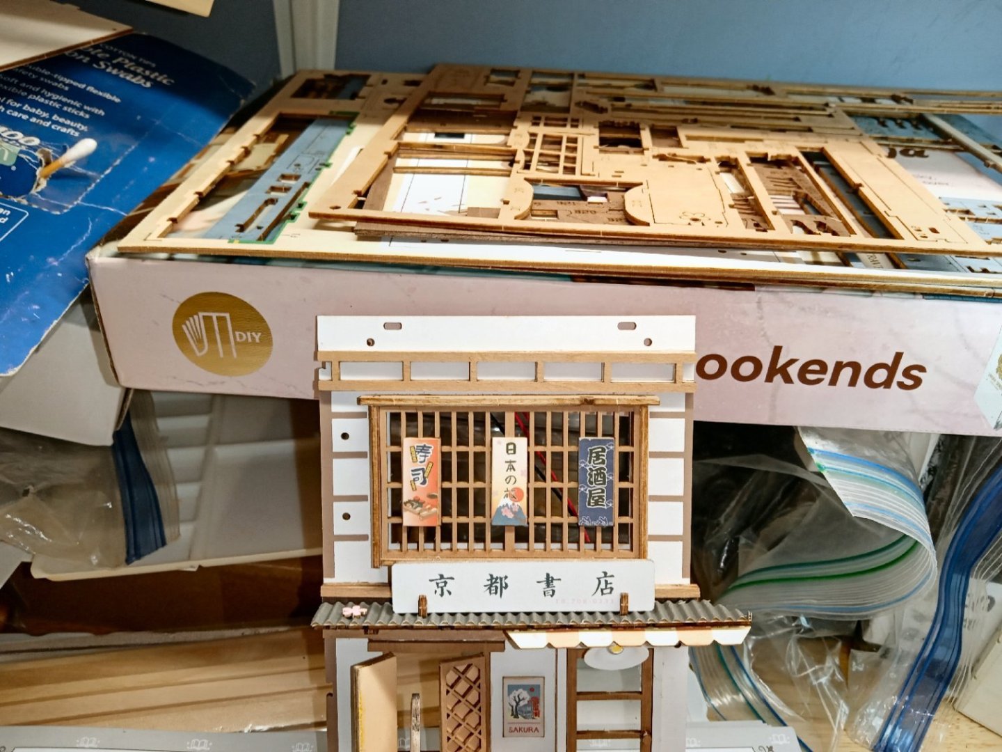
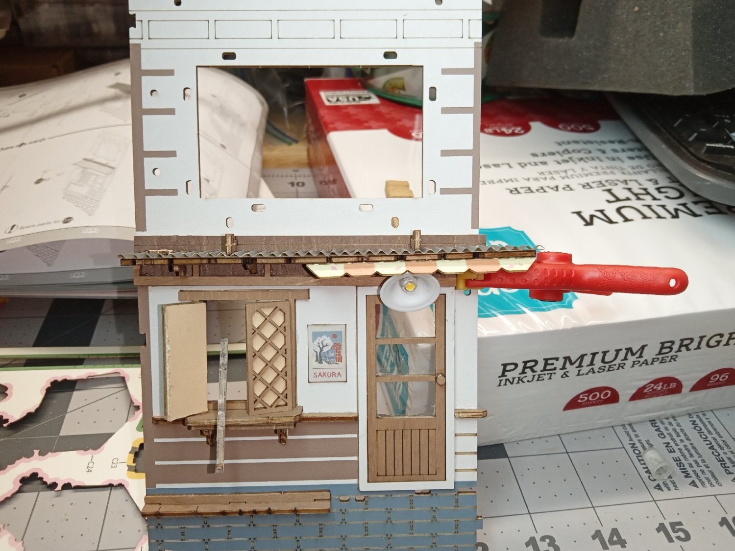
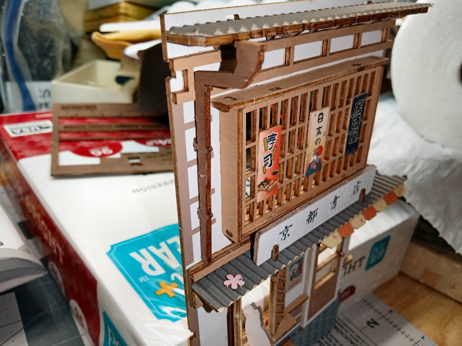
The next day the clamps were removed, and construction of the roof over the window was started. First, the roof beam was attached, then the store sign installed in the brackets on the first story roof.
The sub roof with the rafts went on, next.

The corrugated roof, and the drain pipe were glued in place. I used the brown pencil to color the edge of the drain pipe.

To be continued.


-
Part_013
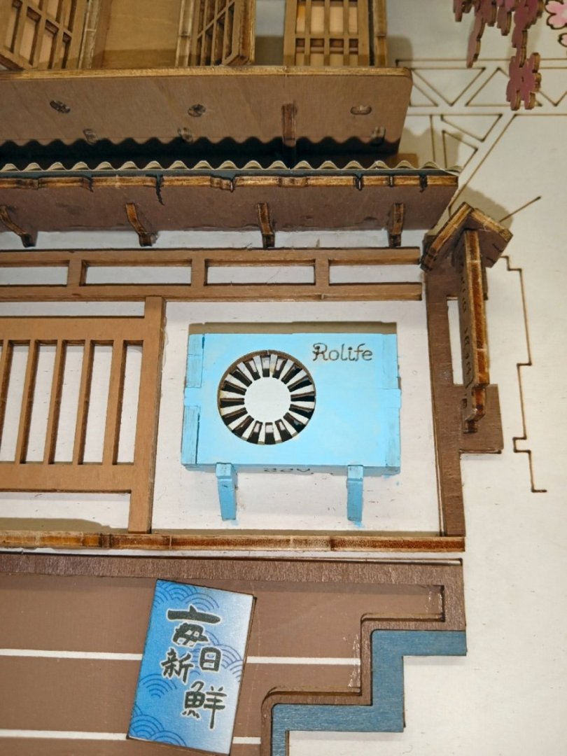
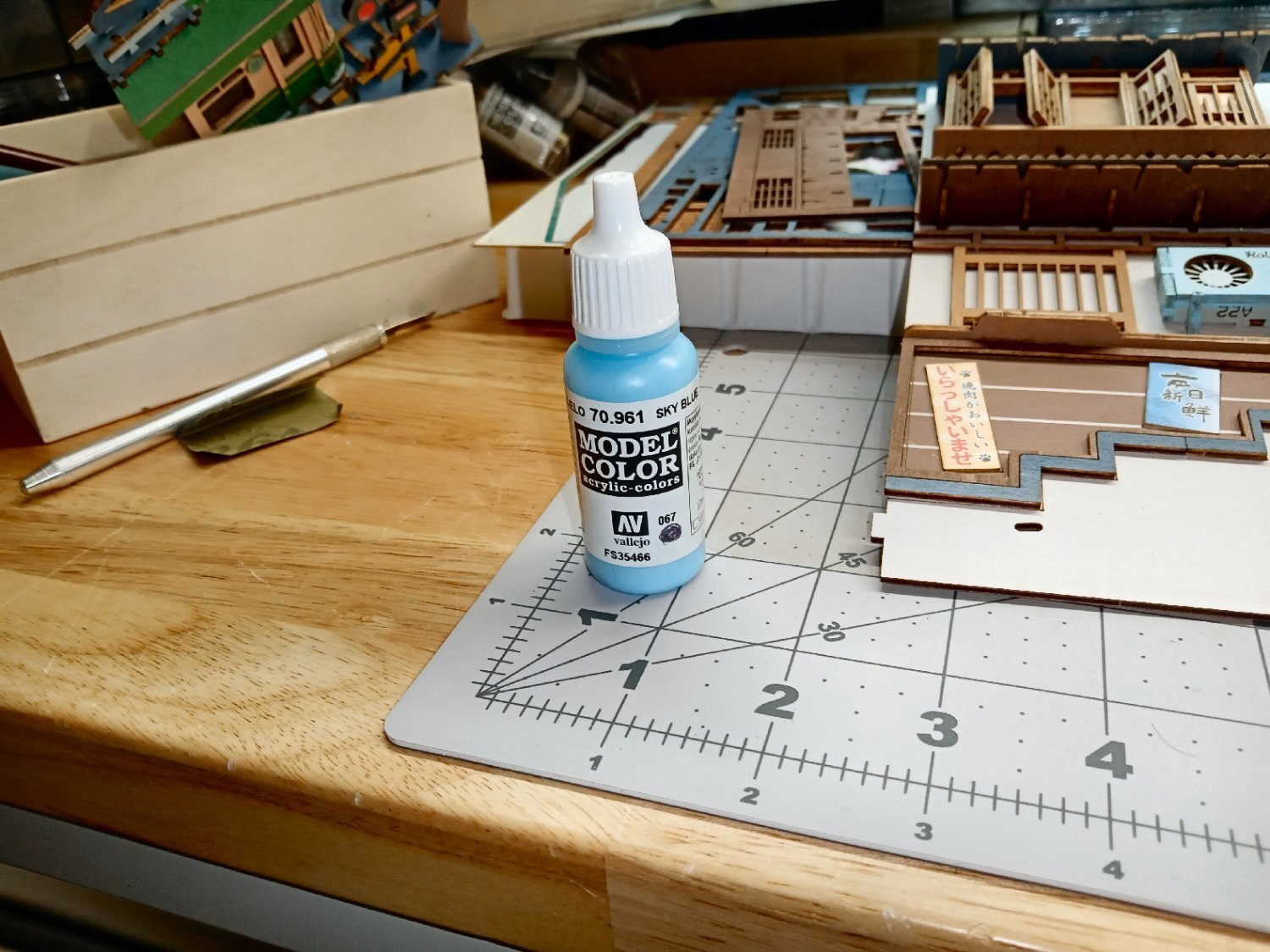
I decided to paint the AC unit, as the brown edges were just too stark a contrast to the light blue of the painted surfaces. I choose to paint it, rather than using pencils, because I did not have a close match in the pencil selection, and due to the tight clearances of the installed unit. I used Vallejo Sky Blue Model Color paint, it also did not closely match the existing color, but I simply painted the whole unit. It took two coats, to fully hide the laser char. I used a brush on the top, bottom, and sides, as well as the raw edges on the front. For the front I used a light load of paint on the end of a Q-Tip, to apply several light coats. I let it dry overnight, and repeated the procedure for the second coat. I used the Q-Tip to paint the front, as I did not want to risk filling in the “Rolife” etched label. I left the center of the bottom alone, as it is not visible on the completed model. In the background to the right, you can see that the first coat did not quite cover the dark laser char.

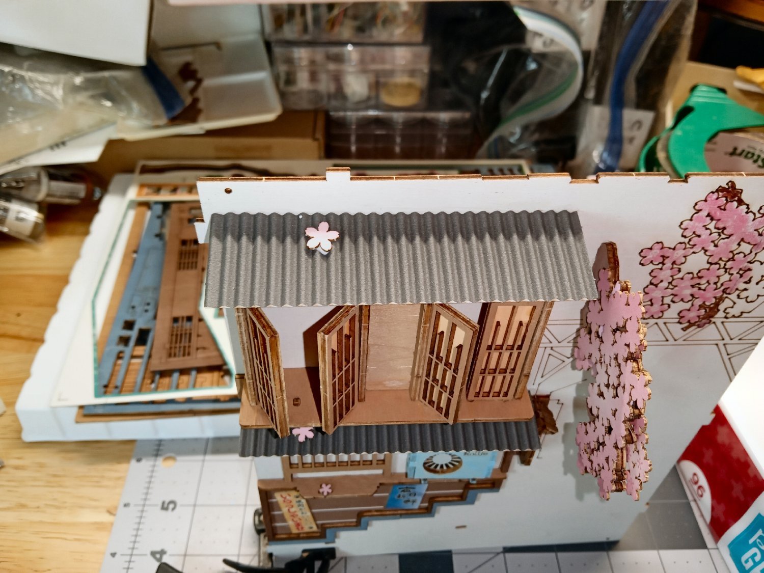
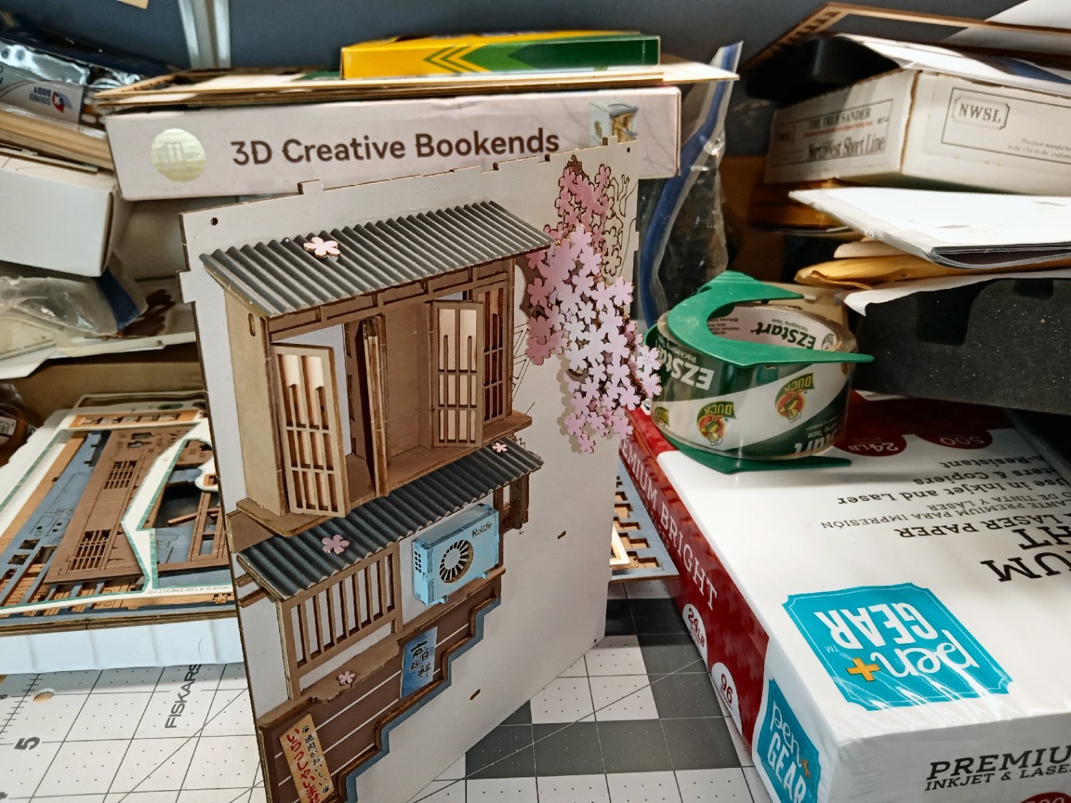
I let the window unit dry overnight. The next day I glued on the corrugated roof piece, as well as a cherry blossom.

This finishes this wall as far as gluing pieces to it. I still have to install the metal corner braces, but will do this when I assemble the outer book covers to the base.
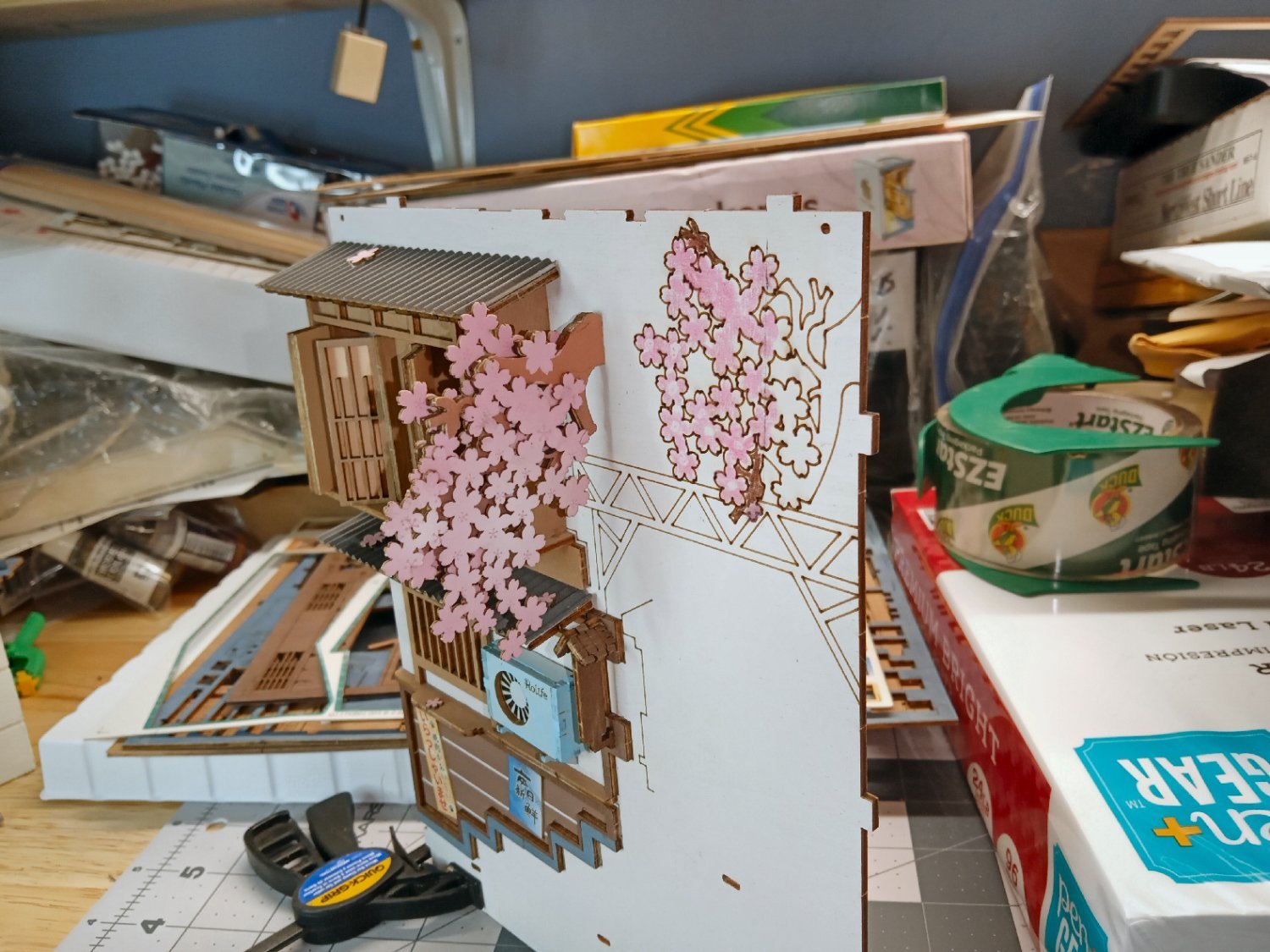
Here are two pictures of the completed side.


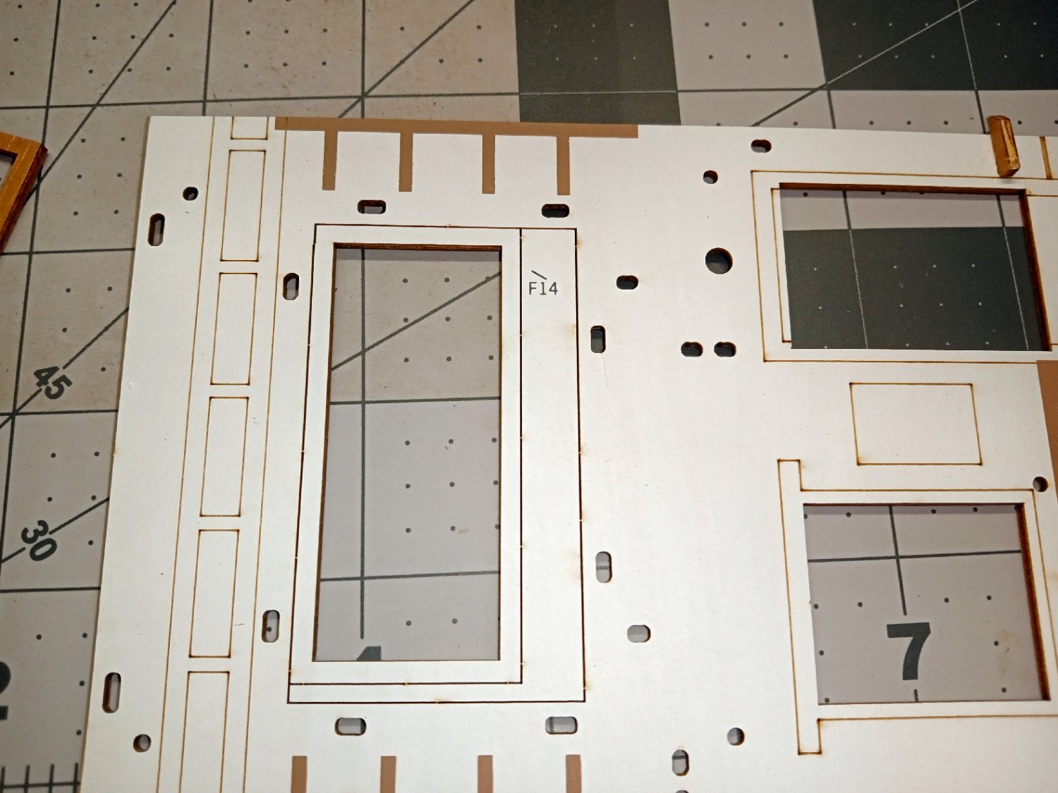
Next, I started on the right-hand wall. This photo is of the raw wall piece.
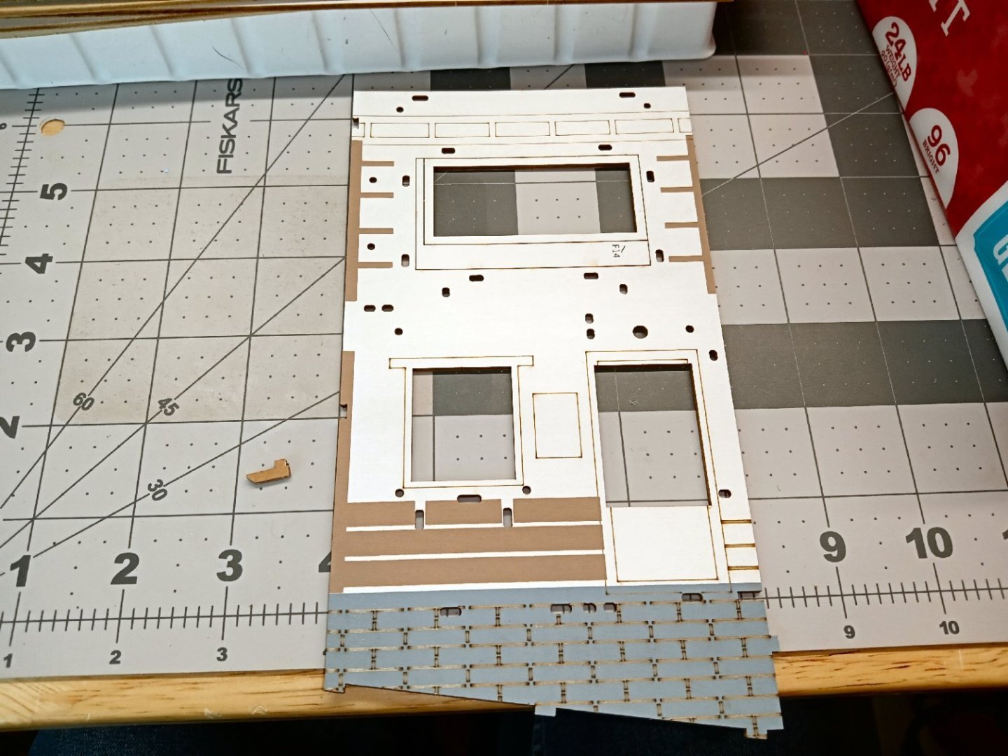
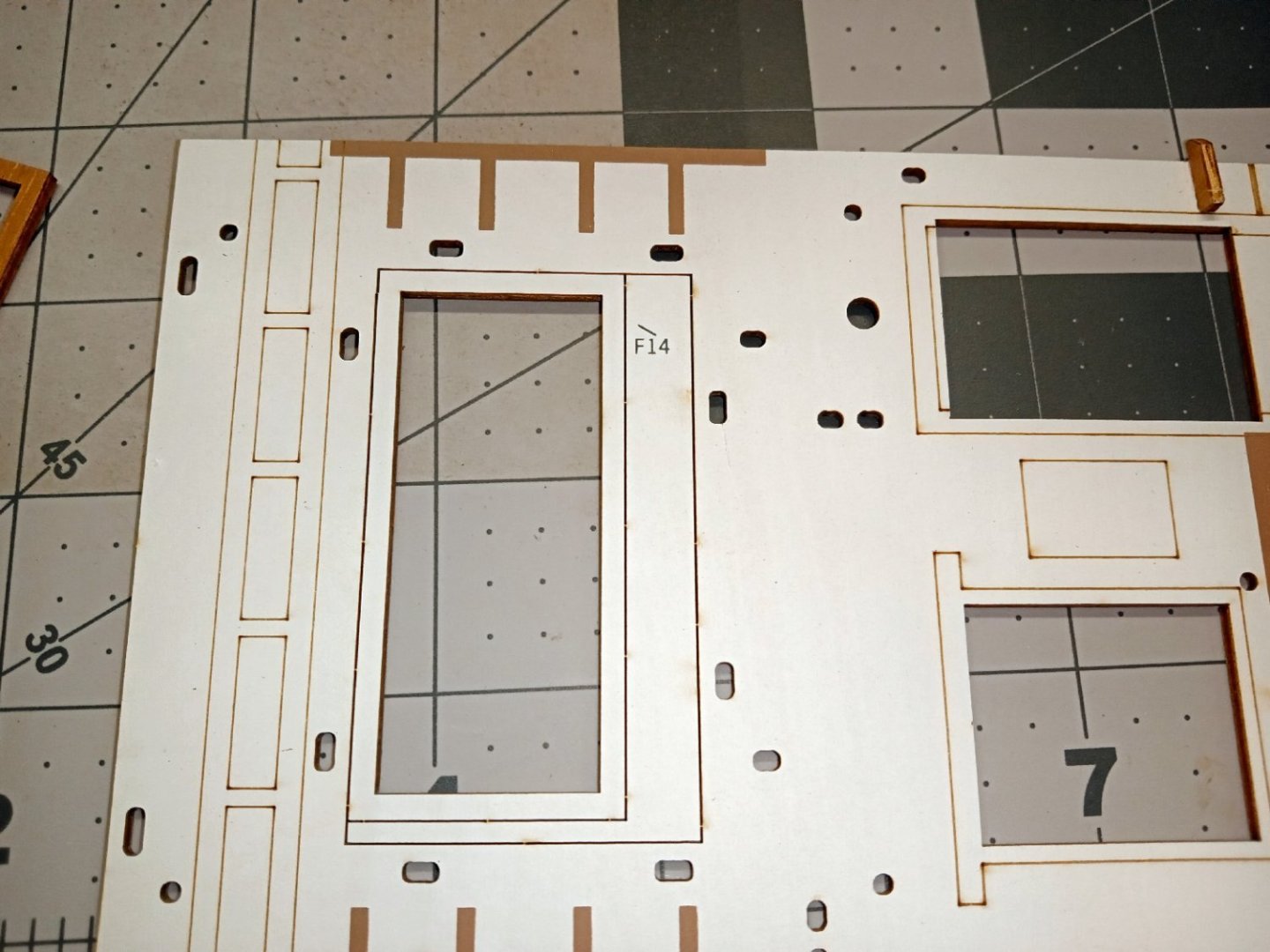
The first step is to glue on the door frame part F14. I spent about 20 minutes searching for this on the parts sheet, then in the box I stored the loose pieces in, then the floor, in a repeating cycle, too no avail! Then I looked closer at the wall section, and there it was in the middle off a larger opening above the door! It looked like just another opening. Yes, “Brain Fart Moment”.
I used a white pencil to color the edges, then glued it and the trim piece to the right of it in place.
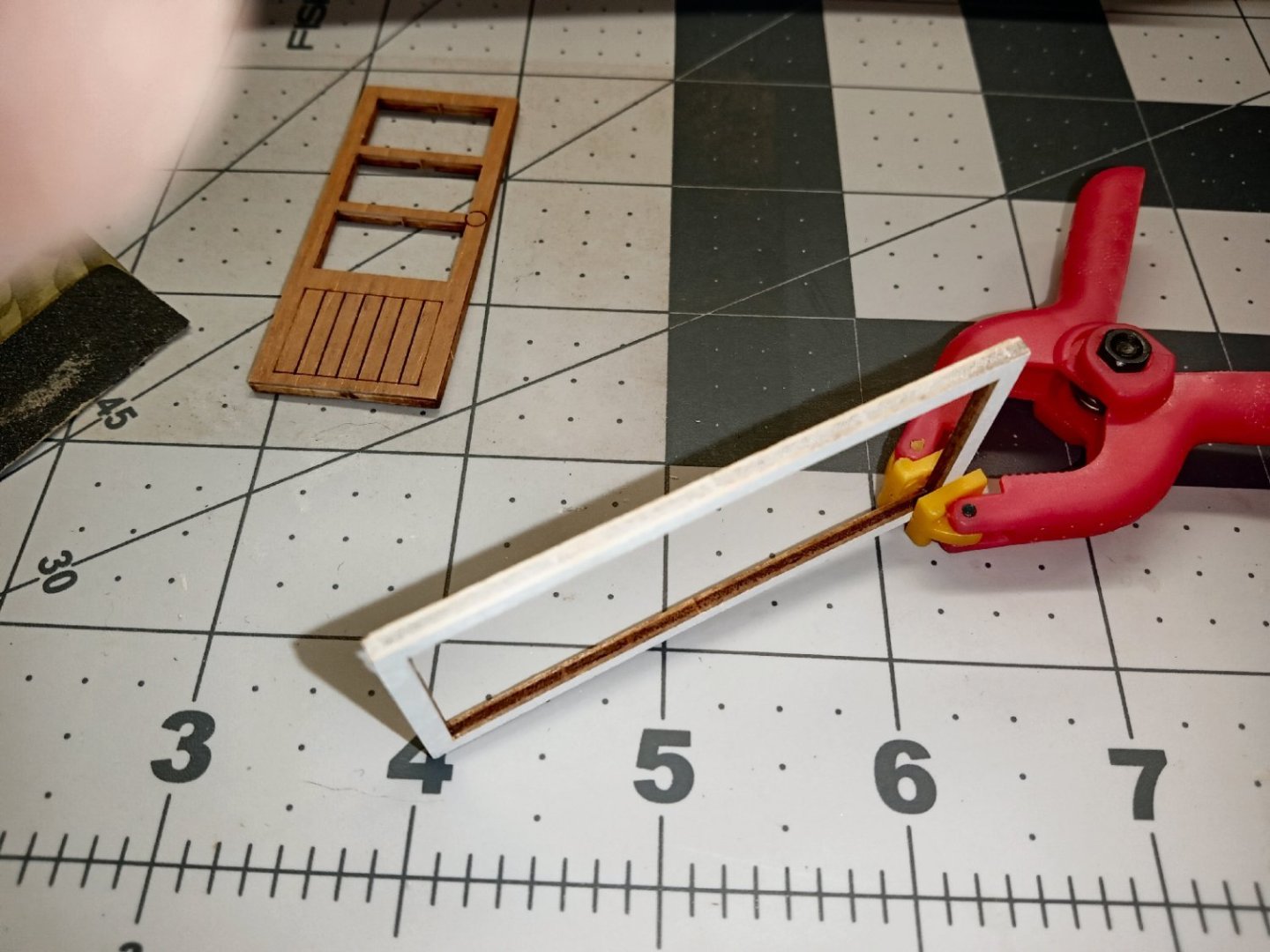

I didn’t at first realize that the trim piece was a trim piece, and it was not quite in line with the ones I added later. Luckily the glue had not fully set, and I was able to twist it the little bit needed to get it positioned correctly.
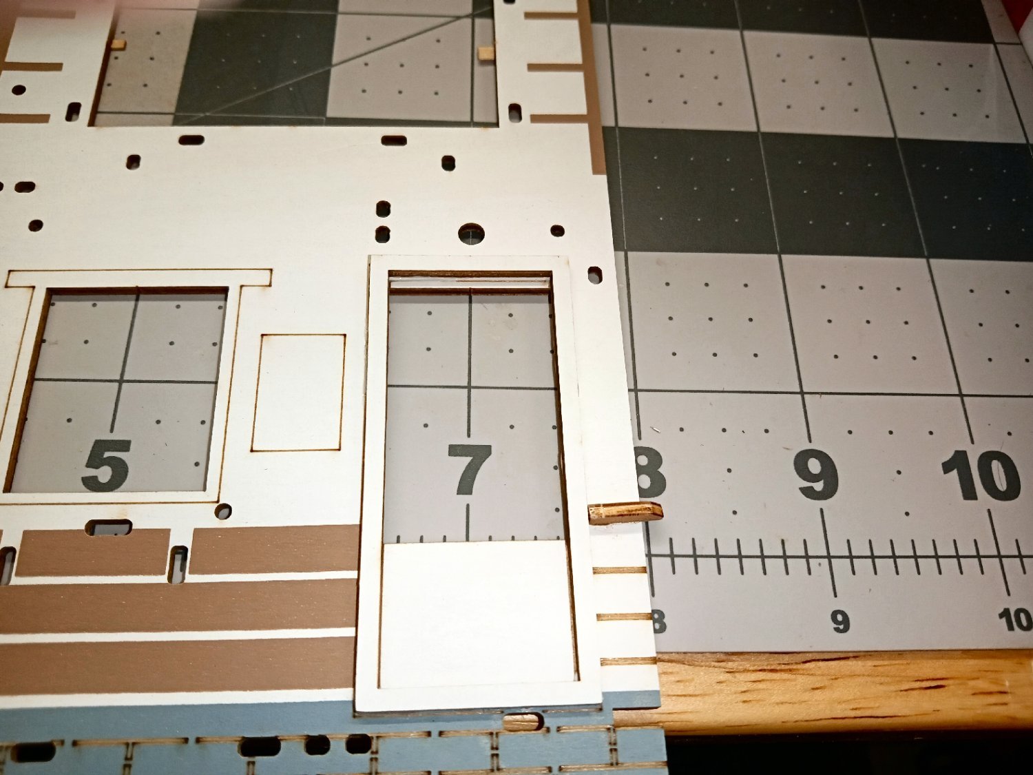
The next step was to glue in the door, then the clear window material. It was here that I first realized that the clear glass parts had a protective film on one side! I missed the note about it when I installed the glass on the tram car!
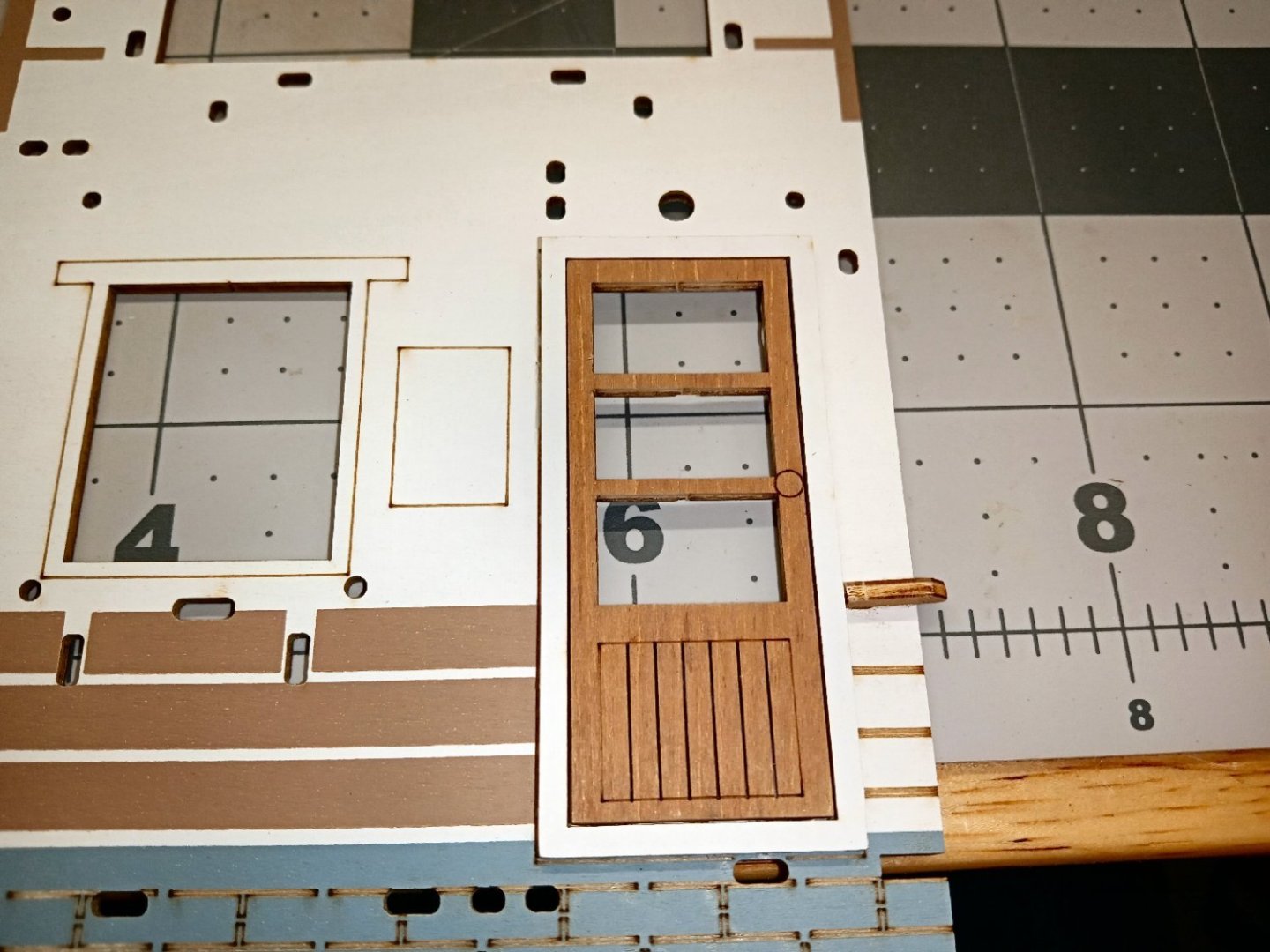
The lower trim piece by the bottom of the door, and the window sill parts were the next ones to go on. It was here I realized about that trim piece on the right. There is second window sill piece that goes on top of the one shown in the pictures. This has the slots to mount the windows and a white cat figure.

The windows were assembled, and left to dry overnight.
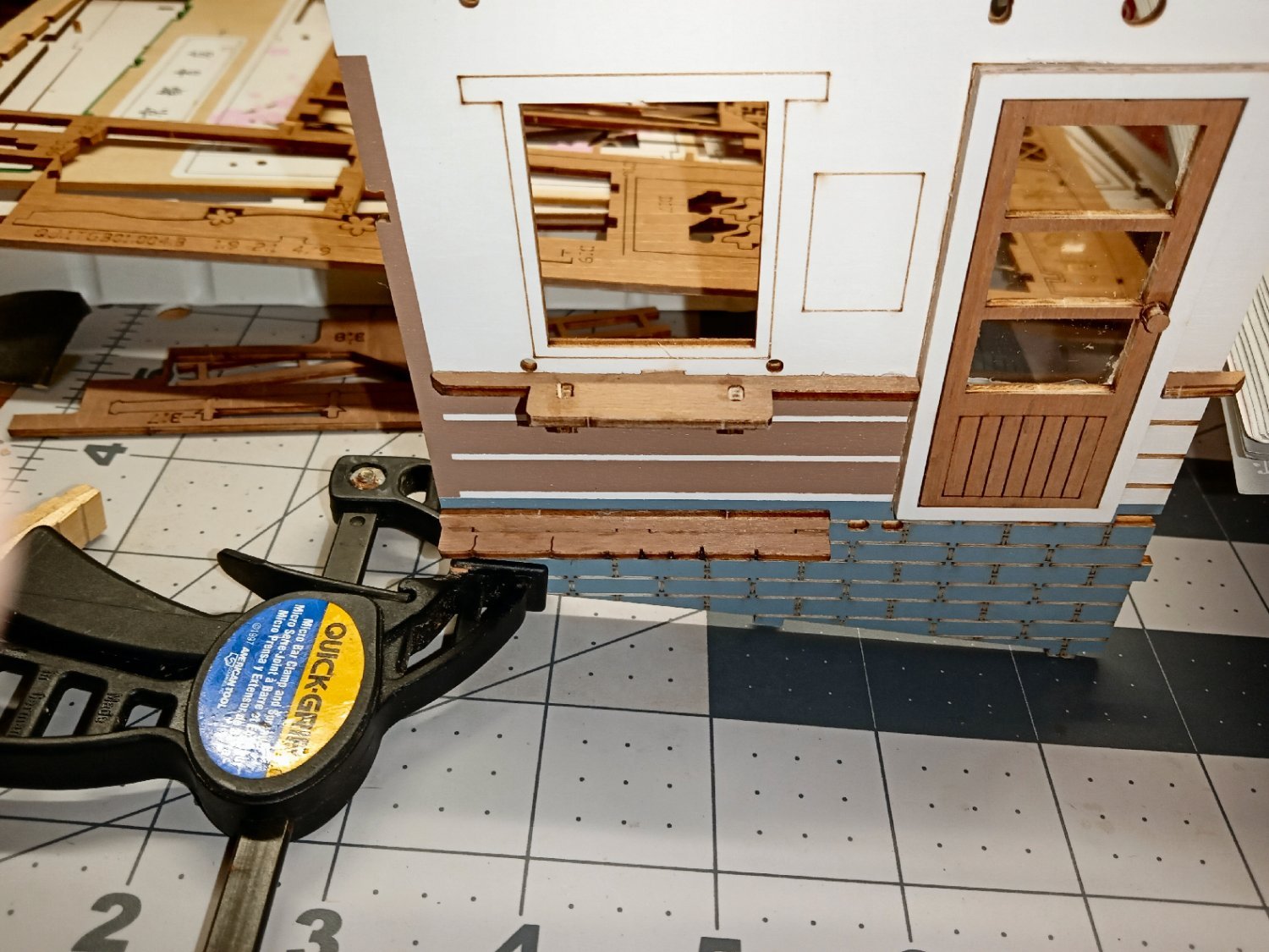
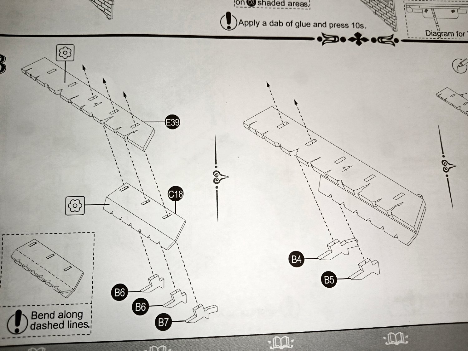
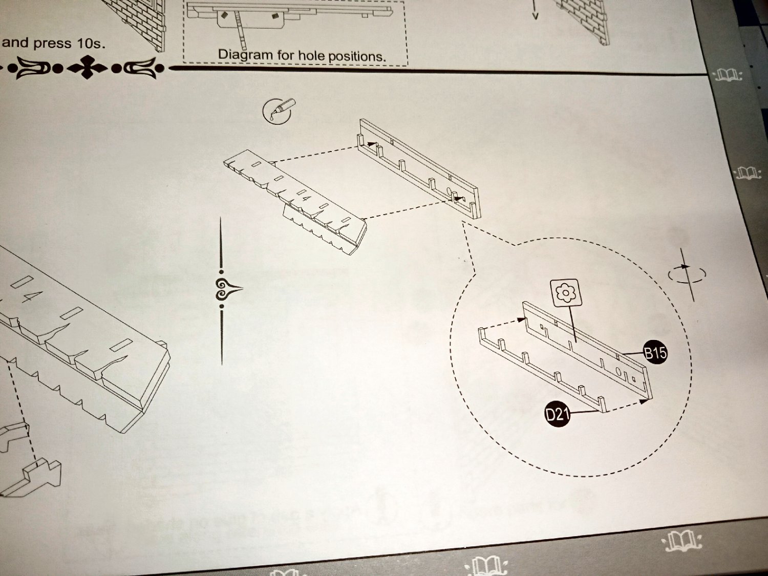
The next several steps I don’t have pictures for. I got lost “In The Zone” while building them, and forgot to take pictures. Below are shots of from the instructions on these steps. Part C18, is a multicolored canopy over the door.
In the picture below, notice the installation of the LED light over the door. In this kit, it is the only LED. The lighting for the rest of the display comes from a window in the top of the diorama.
Construction will continue in Part 14.
-
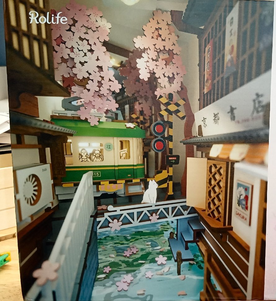
Sakura Densya “Cherry Blosom Train”
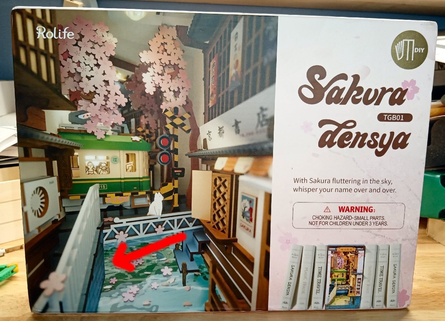
Part_012
The second story of the building is the next section to be built. Construction is started with the floor.

The wall structure starts with the spine.

The back of the roof beam is attached.

Next, the side walls are glued on.


The front of the roof beam is glued in place.

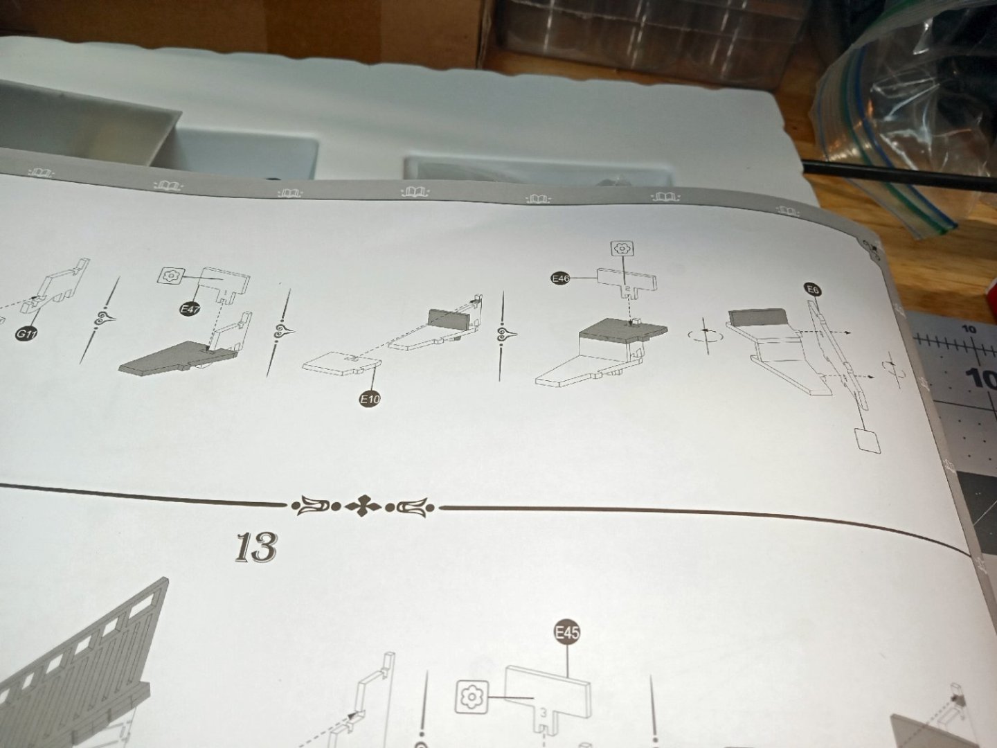
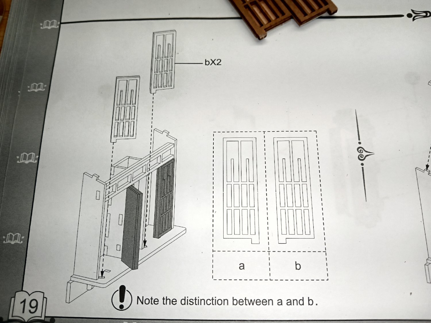
Now it is time to install the windows, built at the start of the thread. The instructions are shown in the two photos.


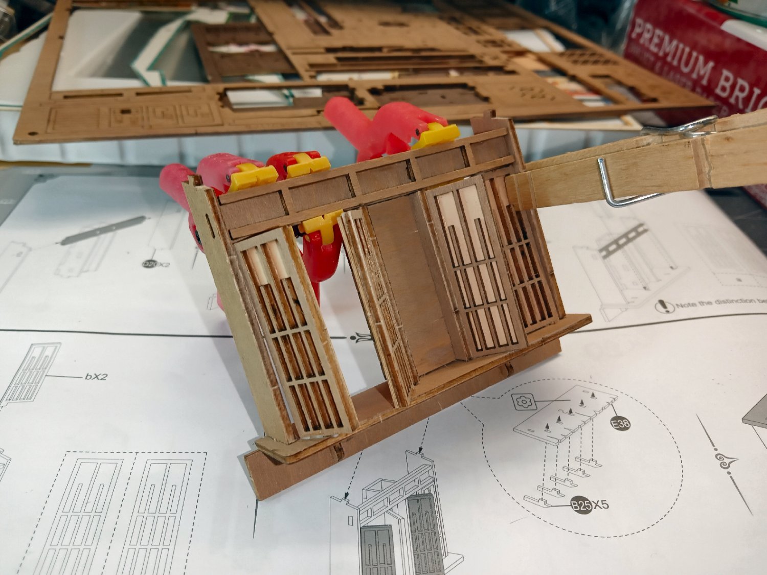
The windows getting glued in. I ran a bead of glue down the hinge edges to better secure the windows.
The clamps are being used as wedges to hold the window edge against the mating surfaces.
Here the sub roof piece has been attached.
I glued the windows to the book cover/wall and clamped it down. Notice the clothespin clamp used as a sprung spacer.

Part 13, will finish this wall, and start the building of the righthand wall.
-
Sakura Densya “Cherry Blosom Train”
Part_011
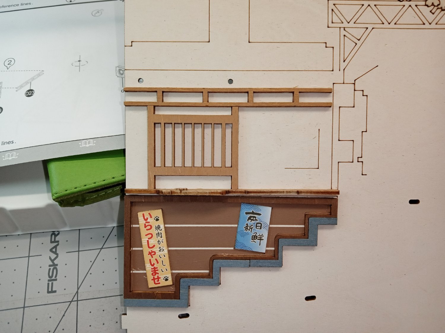
I am going to start building the lefthand wall in this section. This is the wall that will sit against the stair/retaining wall sections I built earlier. Construction starts with a frame around a wooden wall section. There are locating marks etched on the wall to locate all the pieces that will attach to it.
There are two signs that are attached to the wood-colored section. The wall is also etched to indicate their locations. The instructions show the proper orientation for the signs.
Here the first sign is glued on, and you can see the outline for the second one on the left.
The next part to be attached is a balcony floor, with flower blossom. Then a building roof beam, and balcony railing.


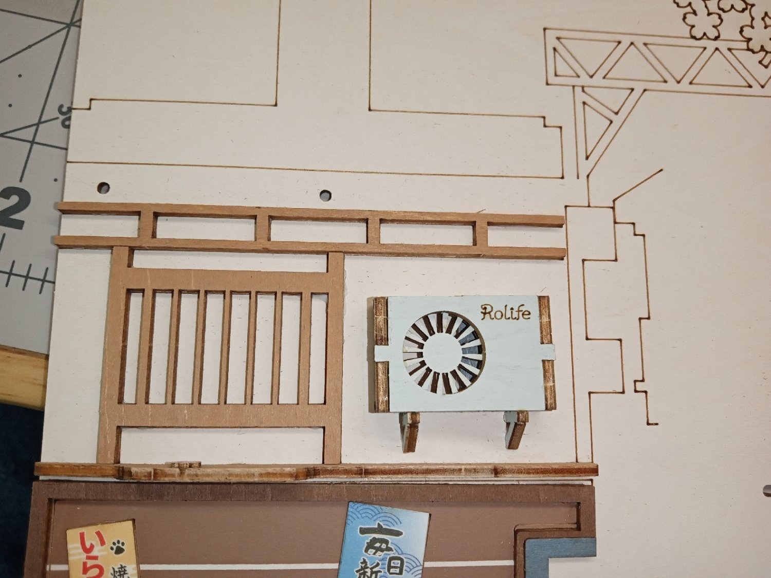
Next the AC unit is glued in place.
The sign built in the first part of this thread goes on next.
I was at Walmart the other day and picked up a 50 pack of Crayola colored pencils. I went through them and found the “Slate” one to come closest to the gray of the retaining wall. I colored in the locating tabs that stuck out of the wall, the front edges of the stone steps, and the edges of the wall cap stones. Below is the before and after photos. The coverage is not great, but it certainly cuts down on the stark contrast between the colored surfaces, and the laser charred edges.
I found the “Brown” pencil to be the best match for the wood tree trunk paint.


Now, back to the wall. The next parts are the rafters and sub roof that goes over the balcony area.
The two pictures show the installed rafter pieces, with two of them having locating tabs for attachment to the wall.

Here is the roof piece attached to the wall. I added a line of glue at the joint of the under side of the roof, and the wall to reinforce this area.
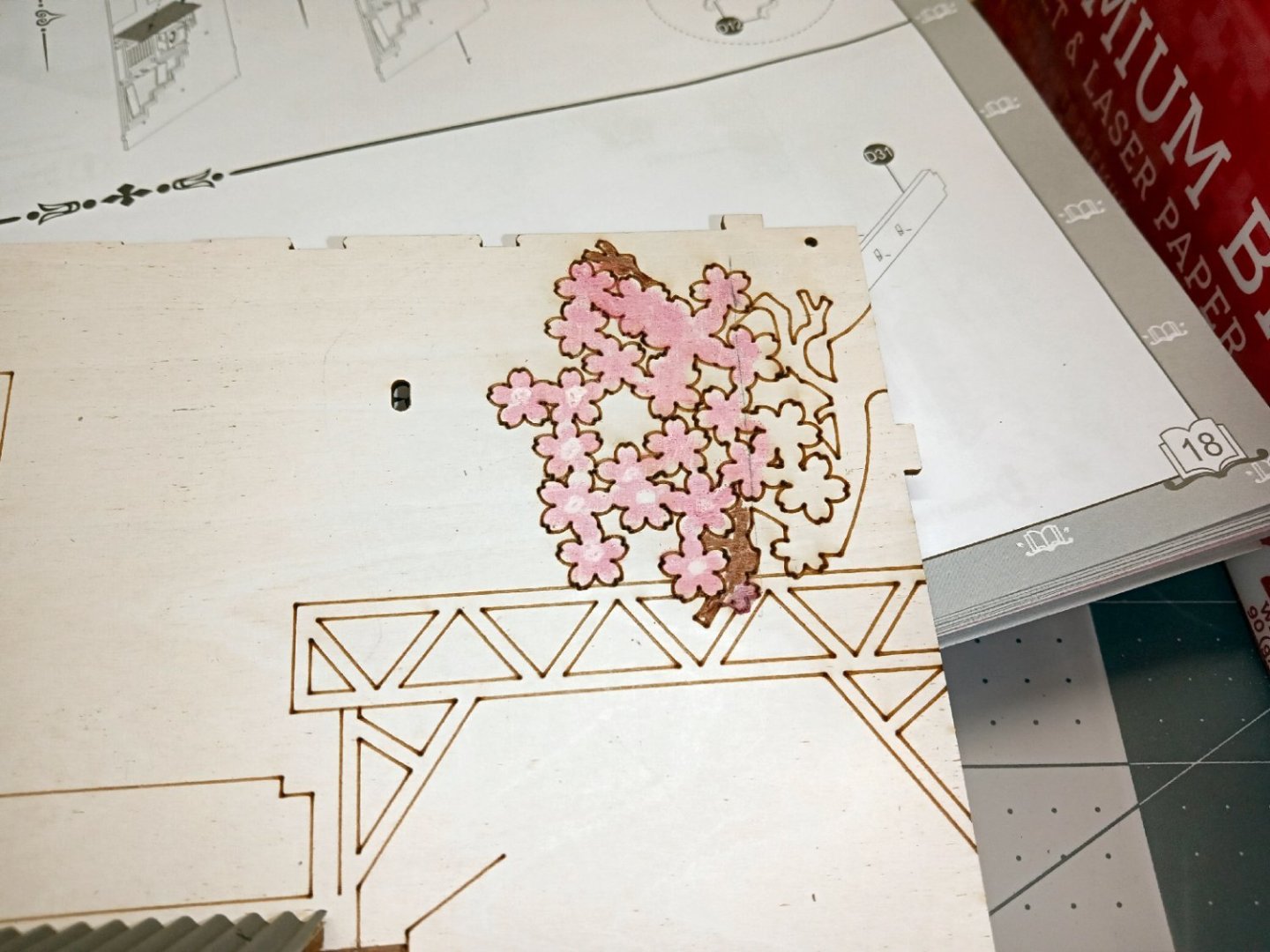
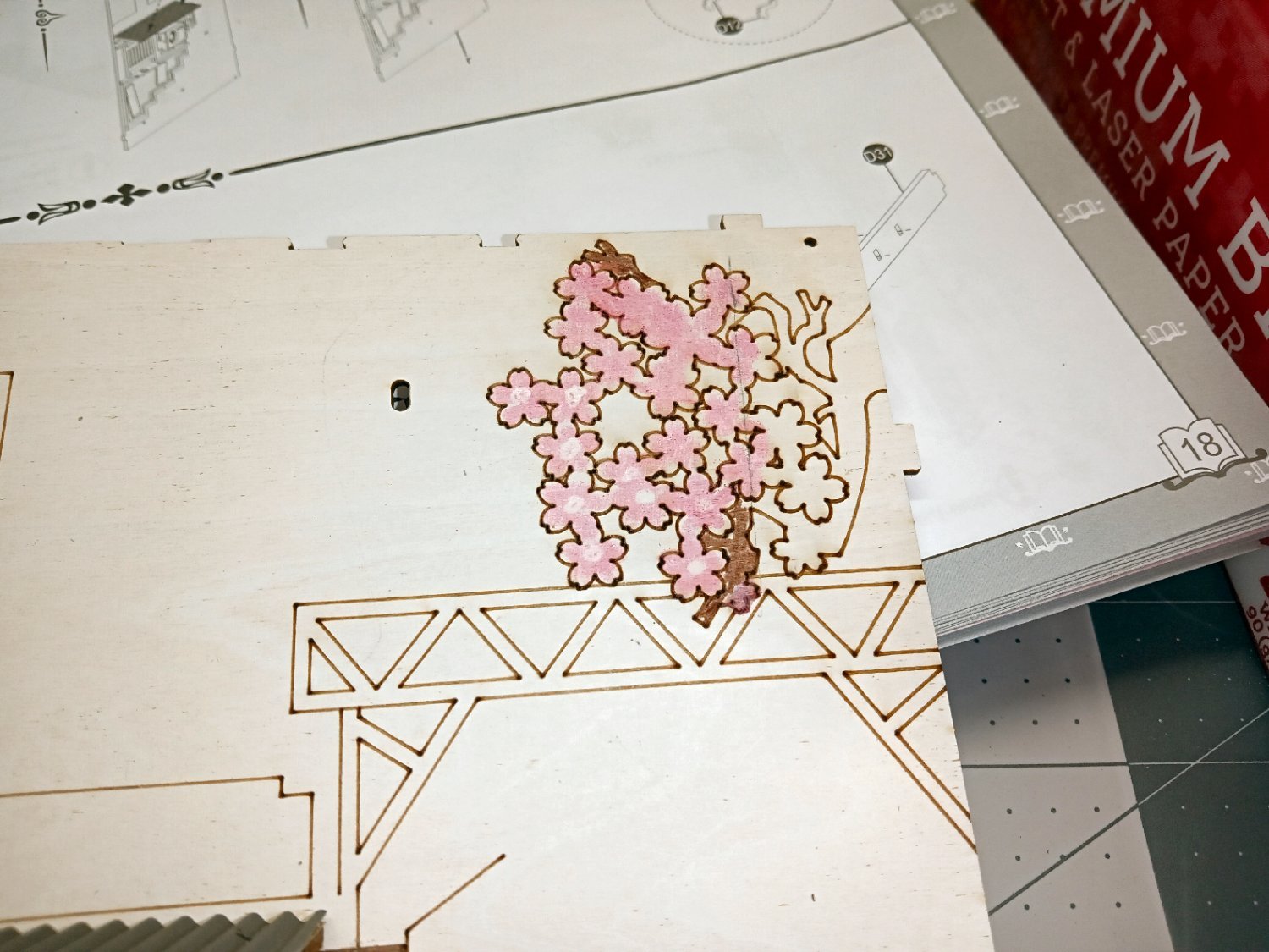
Looking at the right upper edge of the wall I noticed that the cherry branch etched in was not colored. The first tree I build will attach to the slot to the left. I have no idea if this area will be seen in the finished model. As I had the nice new pencil set, though, I colored in the blossoms and branch. The far right of this area will be behind the mirror, so I left it as is.
Doing this showed me one failing of the pencils, you cannot combine colors to get a different shade! Once one color is applied, the pencil “lead” of the next will not mark the first. I applied white to the flower centers, then attempted to add in pink to tone it down. No luck. The pencils have a similar problem with any glue covered surfaces.
Next the first corrugated roof covering is glued on.
In Part 012 I will continue with the wall construction.
- Canute, mtaylor, Old Collingwood and 3 others
-
6
-
Part_010
This Part will be a short one, as will be explained later.
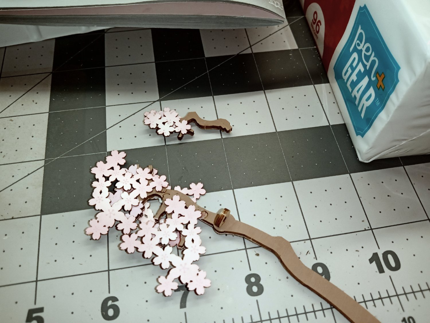
After the glue on the walls had set, I added the cherry blossom to the top of the railing, at the joint between the two sections. As well as decoration, it serves to lock the railing sections in alignment.

Next, I glued the two blossoms to the bridge front.
As the next steps in construction will start adding sections that cover over areas of the stream, now was the time to add the floating blossoms to the stream. I started by gluing the four corners of the ripple sheet, using the Canopy Glue, then clamped the spots. I used only a small dab of glue.
Three sizes of blossoms were glued on, using cross marks etched on the streambed as reference.

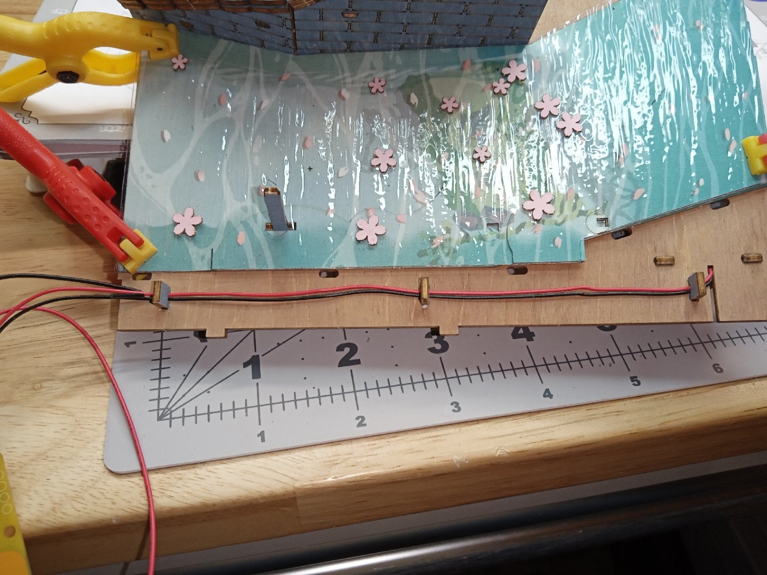
Using wooden staples supplied with the kit, I secured the LED power wires to the base plate. For now, this finishes this part of the base construction. Many more areas have to be built, before we get back to this assembly.

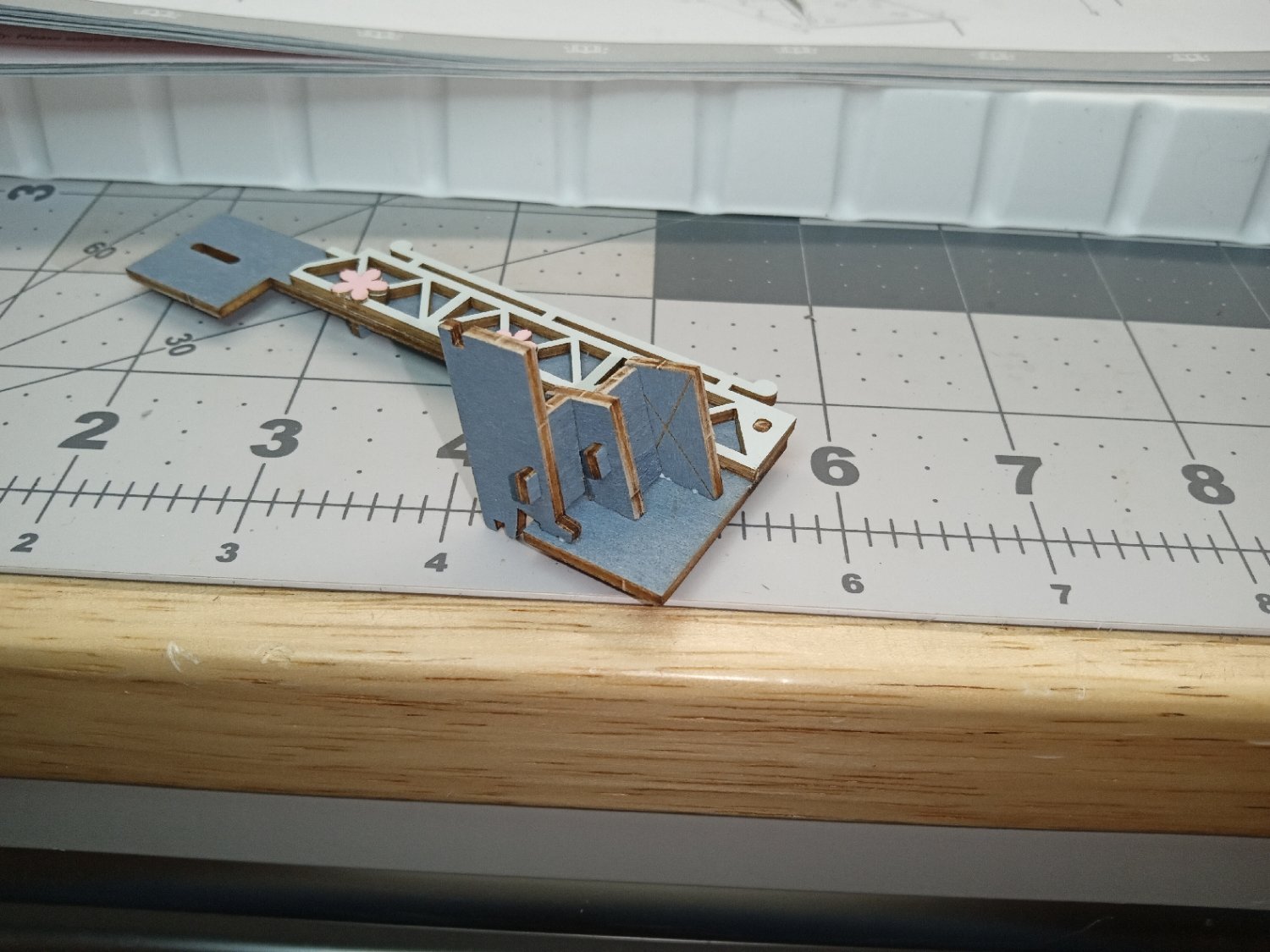
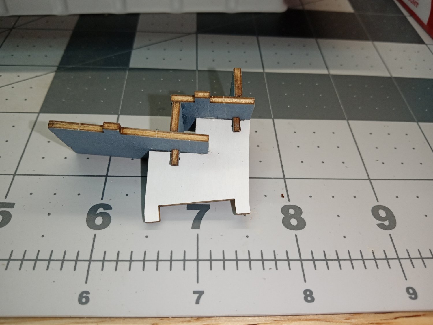
The next task, is to do more assembly of the bridge structure. The picture below shows the beginning of adding steps from a landing at the stream, to the bridge roadway. I chose to not attach the pilings B20 and B21, at this time. Rather than risk them being misaligned when the completed bridge face is installed to the base, I’ll wait to add these when that time comes.
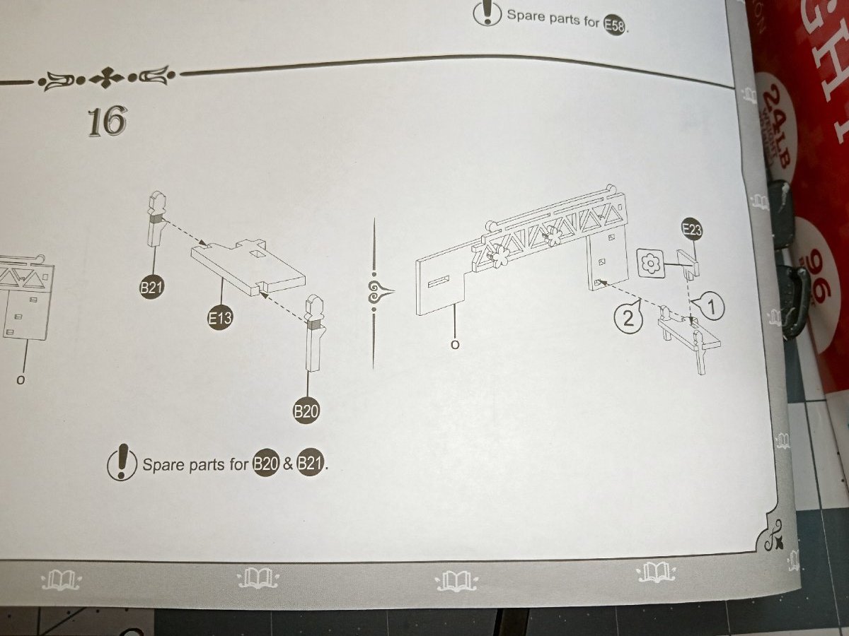
These pictures show the steps completed.

Now comes the explanation for why this section is so short. The next steps would be to add some support walls for the left side of the bridge, and assemble the bridge to the base. There is a problem, though. The next ten pages of instructions detail building both of the side walls of the diorama, after which the sides and the tram base are attached to the bridge and the base plate, in one fell swoop. Rather than getting to that point and finding the bridge does not line up, I’ll wait and install the bridge at that time.
So, this is as far as I’m going to go with building this section now. When I return, I will jump to the building of the two side assemblies.
-
Part_009
The second wall section is built almost the same as the first one, detailed in Part 008. So, I will mostly just show the sequence, and report major any differences.


The first difference is gluing on another cherry blossom, to one step. Another difference between the two wall sections is that the front edge of the steps is detailed as chipped stone, rather than the straight edges of the previous wall. These edges may be more visible in the finished model.
This wall has horizontal sills at the top of the right side of the wall. They are installed like the long stills, printed side down.

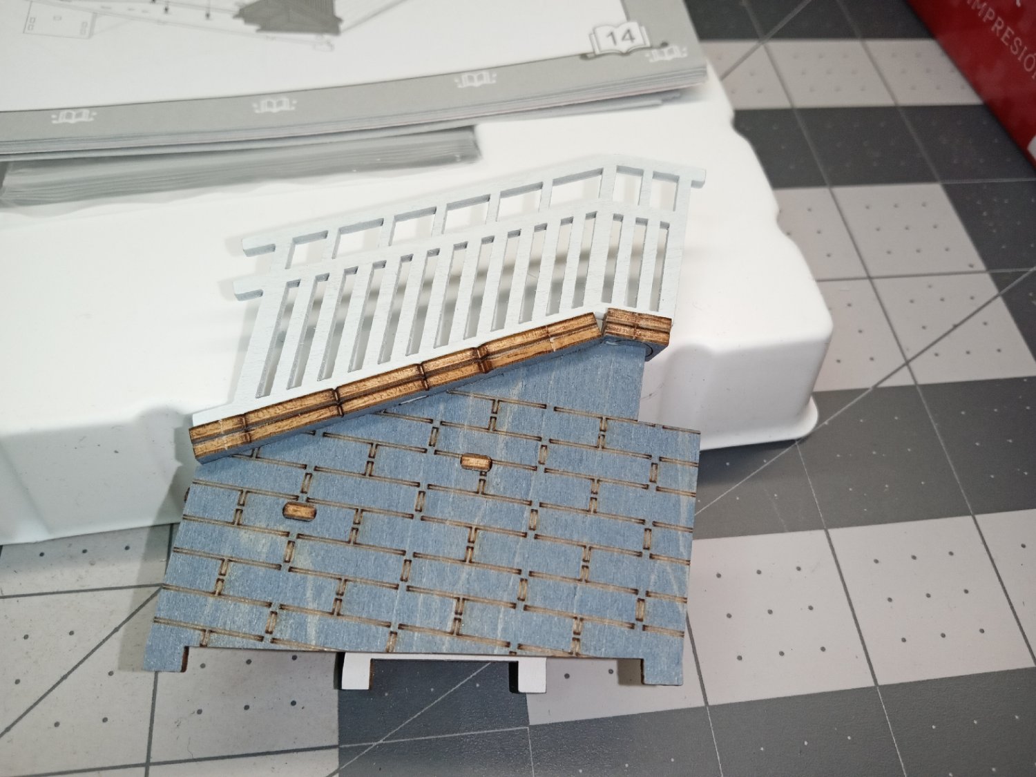
These two pictures show the completed second wall.
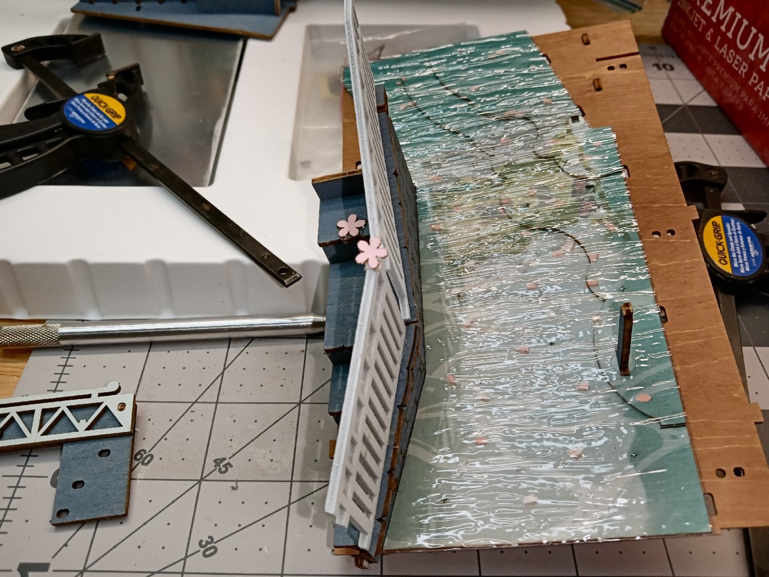
Now that the walls are built, it is time to install them in the scene. I had a problem with this! Even though the stream bed pieces, were located by the piling in the foreground, the edge the walls butt up against, over lapped just a hair into the area the walls slotted into the base! The manufacturer should have had me install the walls, then the stream bed. I did not want to risk cutting the bed, and possibly leaving a gap between it and the walls, so I took a long time carefully forcing the walls into place, tightly wedged against the stream bed. As you can see below, this caused the walls to not quite line up at the seam! I spent more time forcing them in line, then holding them while the glue I spread over the seams set. In the end, it turned out all right, but it was a pain.
The only thing that I could not quite fix, was that the lower wall does not quite sit flat against the base at the left side, there was no way to clamp this, as between the sloped wall, the angle bracket under the base, and the railing base, there was nowhere for my clamps to hold. No matter what I tried, they all slipped off, it is only a very small gap, and is hidden by the streambed piece, and should not be visible, but it annoys me.
After, the glue was holding, I clamped the seam as best I could and set the assembly aside, to fully dry.

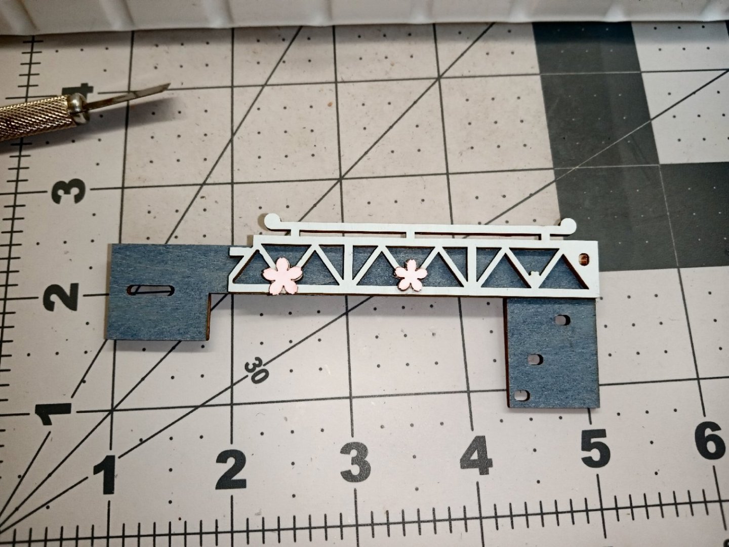
While waiting for the walls to dry, I started on the face of the bridge that crosses the stream. Below are the first set of parts that build this structure. The small gray tabs are used as keys to lock the larger pieces in alignment.
Here the parts are assembled and glued, I spread glue over most of the back of the white piece, to keep it from delaminating in the future.
This picture shows the back, with the locating tabs.
I then added lots of clamps, and set it aside to dry.
After the glue dried, I removed the clamps, and glued on the cherry blossoms.
I would like to add that I have been using both the Spell Check and Grammer Check feature of Word 2013 (mainly because I forgot to turn off the Grammer Check when I recently loaded it onto my new computer), for these latest articles. What makes me bring this up, you ask? Well, many years ago with an earlier version of Word, I wrote and article, and used the Grammer Check, and hated the results! For instance, one sentence started with “Like the Craftsmen of old,…”. The Grammer Check came back and “yelled” at me for not using a gender-neutral term like crafters, or crafts person. The whole article was torn apart with similar criticisms. Well, I used Craftsmen for a specific reason, and most of the other check marks were just nit picking, similar ‘errors” not any real errors. So, for over a decade, I’ve had Grammer Check turned off.
They seem to have updated the code, and all the things it now dings, are actual Grammer errors. Thank you, MS!.
-
Part_008
The next sections to be built are the retaining walls, with steps and railings, on the left-hand side of the diorama.
The front most/lower section is built first. This is the section in front of the cherry blossom on the railing. Construction starts with the steps.
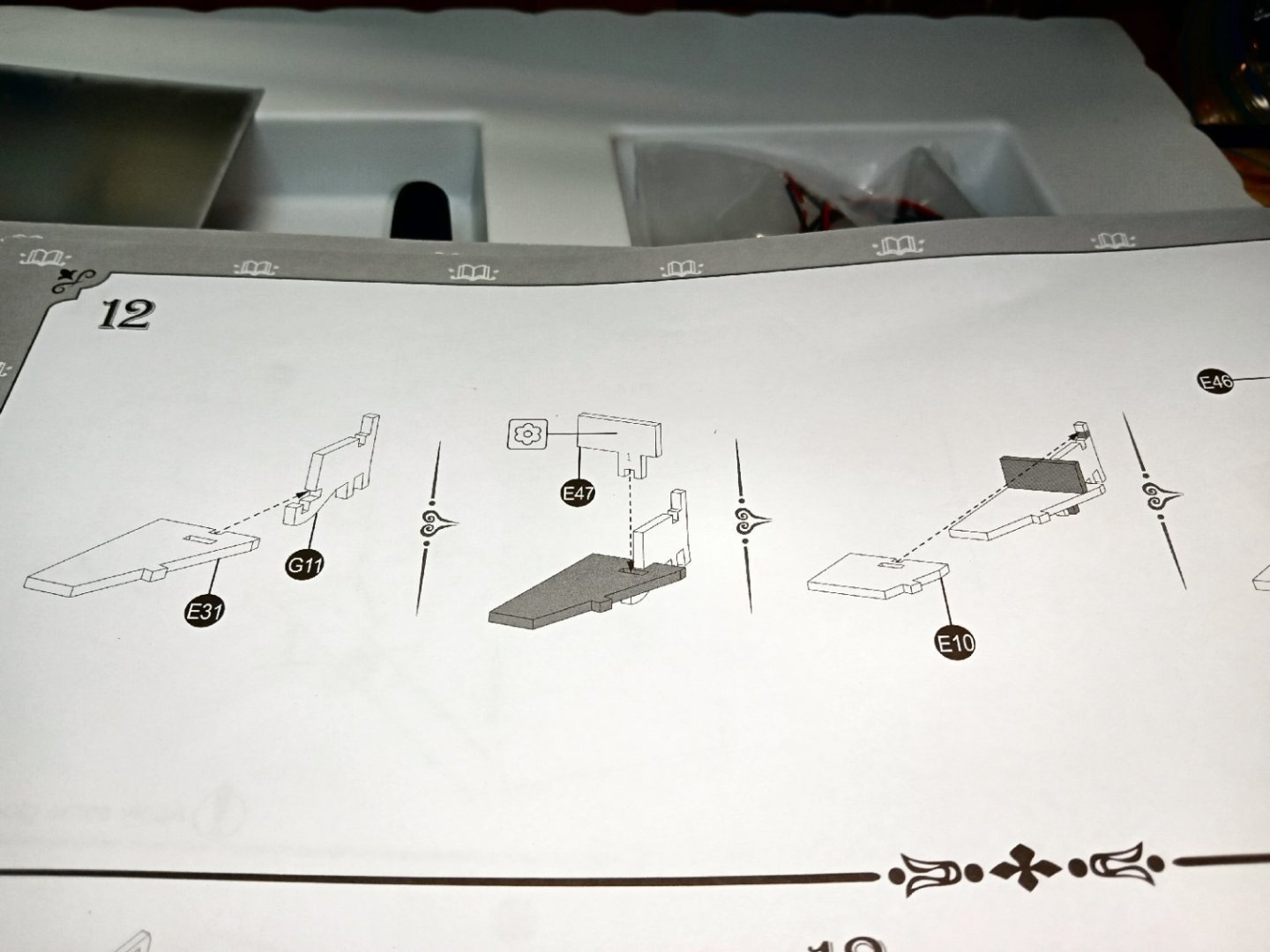
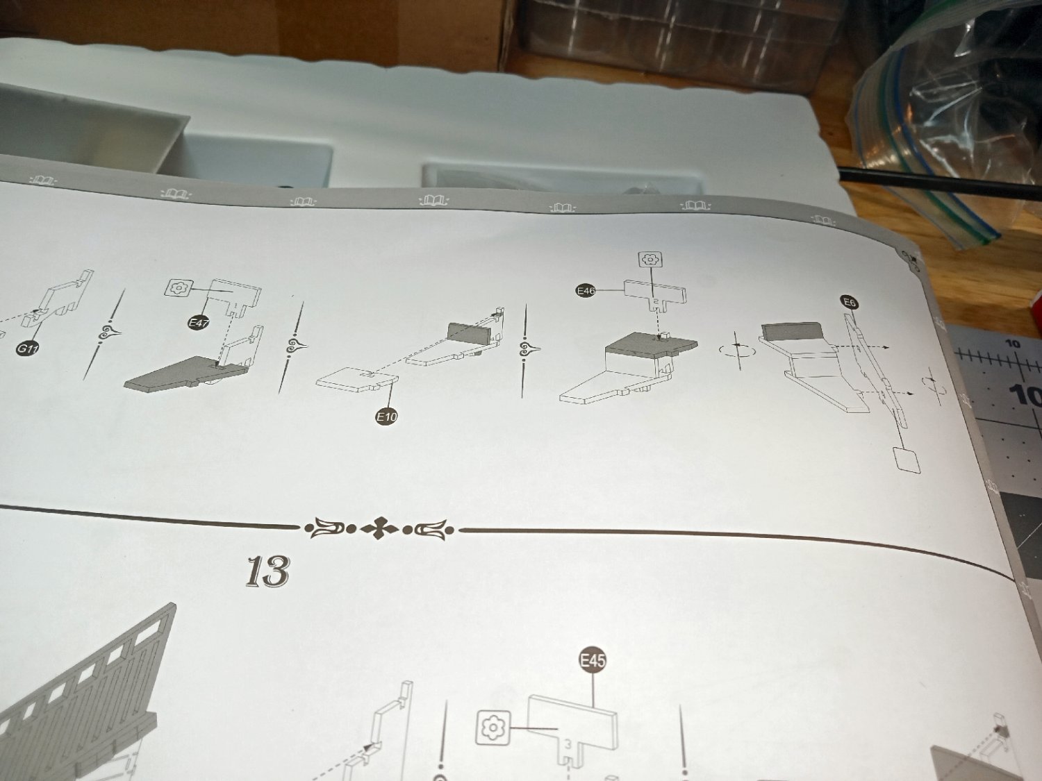
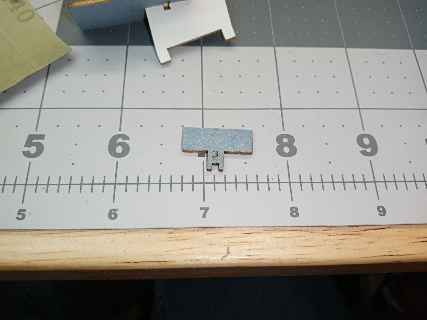
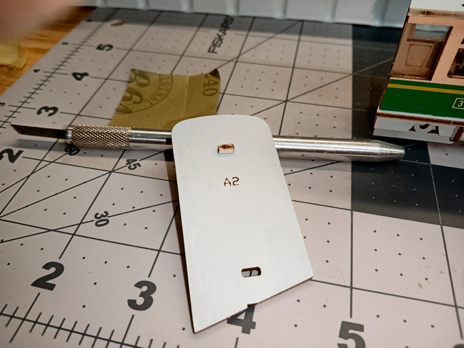
In the instructions above, note part E47. It is shown with the printed side facing the page. The manufacturer helped the builder by printing a character in the tab area, to help you determine which is the printed side, after the step face is removed from the parts sheet (see picture below). They did this on all the step faces.

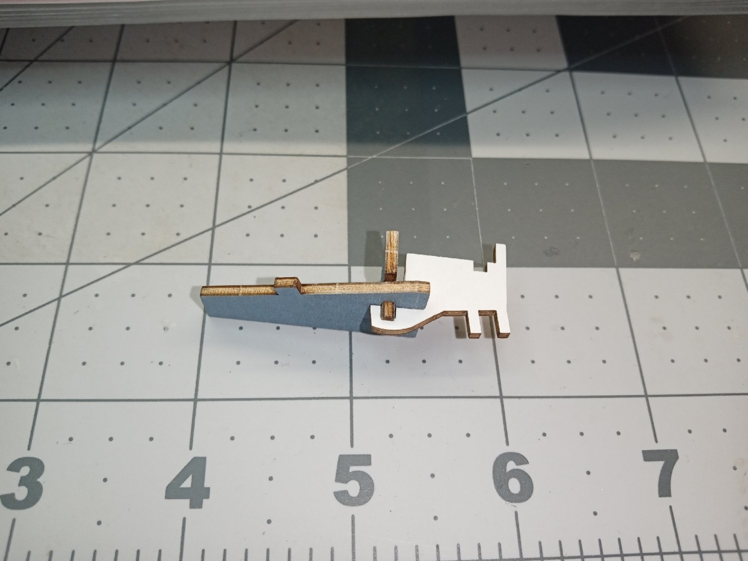
Construction starts with the lowest step, and its internal support. Two views are shown of the assembly below. The white piece is the support.
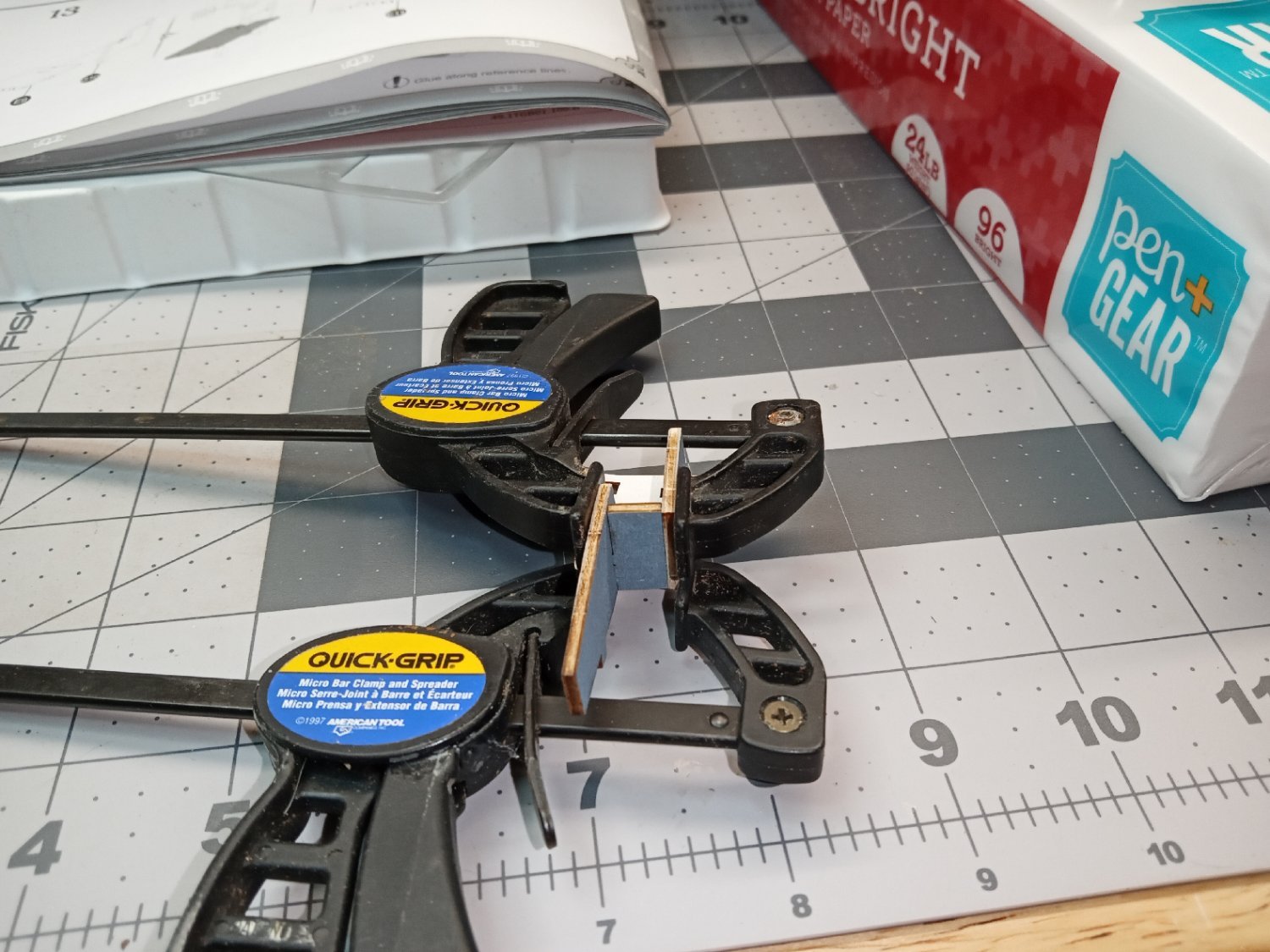
The second step is now installed. The step face and step were not sitting together, so I glued the joint, clamped it, and let it sit for a while.

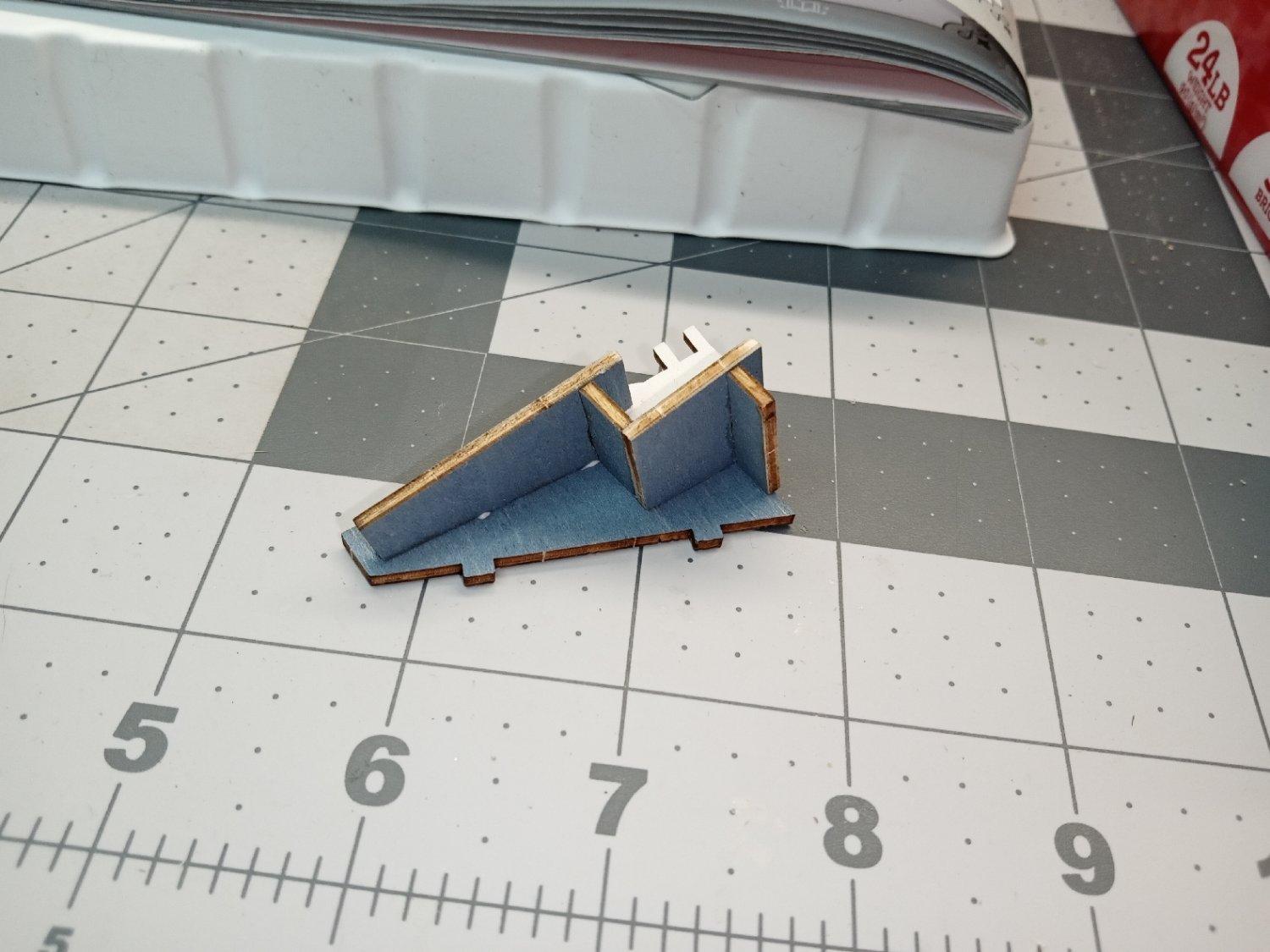
The face of the next step was glued on. This face will mate with the step on the second wall section, that is detailed later. After the face piece was attached, I assembled these parts to the retaining wall face. I glued the joints between the step section and wall piece.
This picture shows the wall side of the assembly. If I could find my colored pencils, I would touch up the exposed tab.

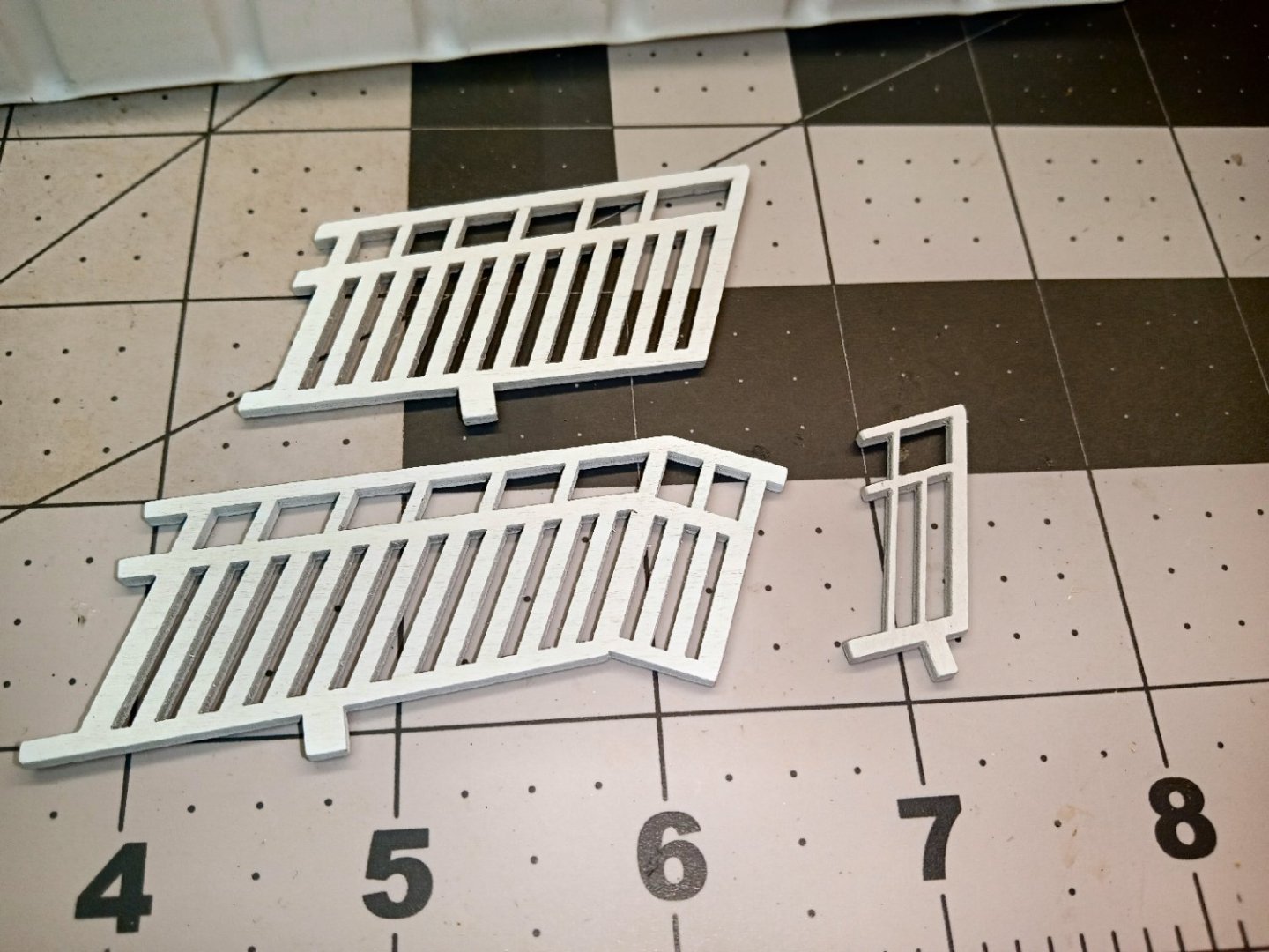
The kit box had a bag with three railing sections in it. Two of these are used for the two retaining wall sections detailed in this and Part 009. The third is used for a small section of these walls that extend past the front edge of the diorama’s “book” covers.
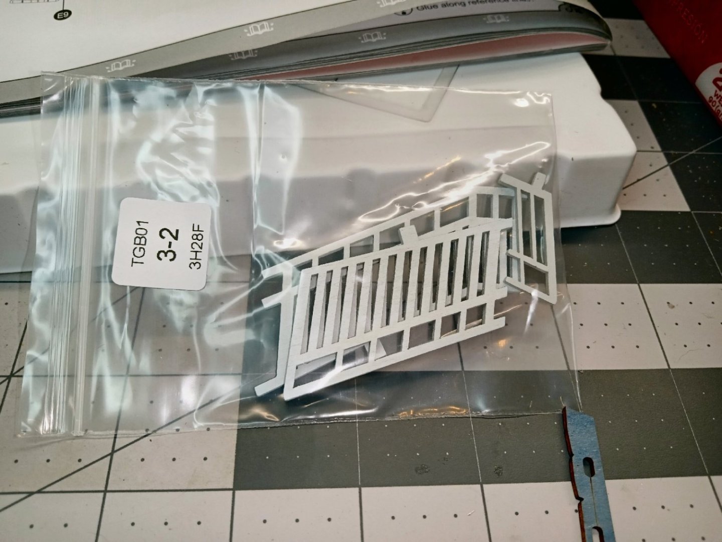
The railing section in the top of this picture is the one that will be used for the wall section being built now.
The top of the wall has a two part stone sill, with the railing mounting to the sills. The sill is two layers. The first layer is shown below, showing the print mark line. This side will go down, when installed.
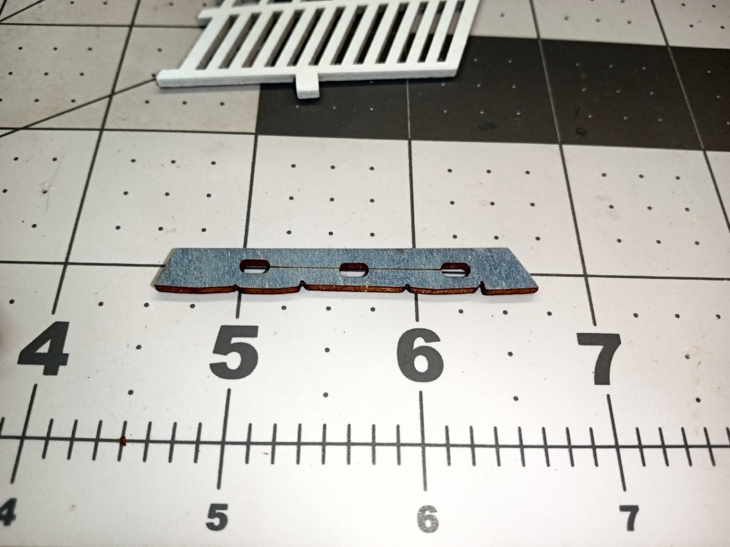
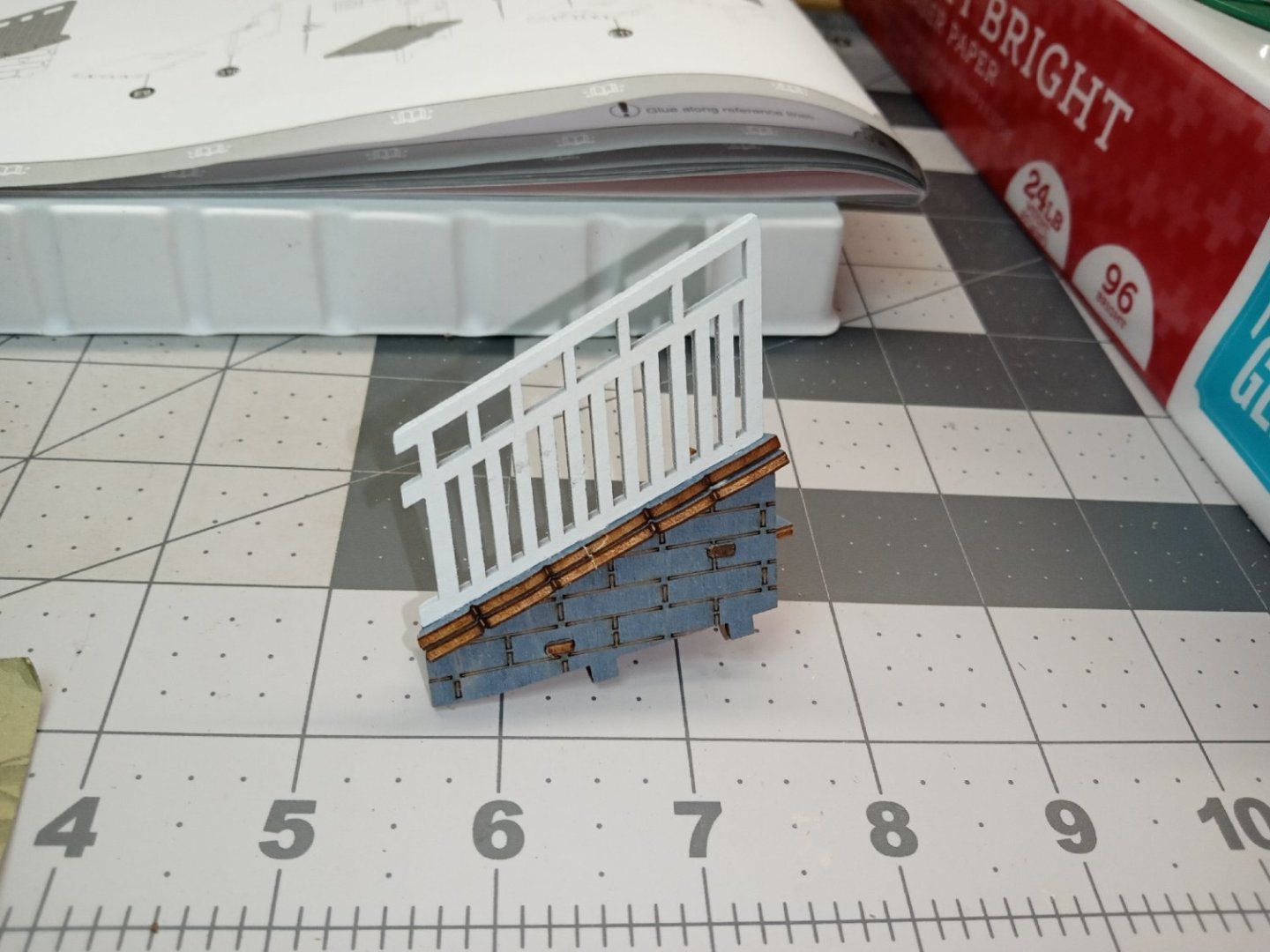
Here it is glued in place, with the piece for the top layer shown on the right. The top piece has a similar printed side marking, which also goes down, when installed.

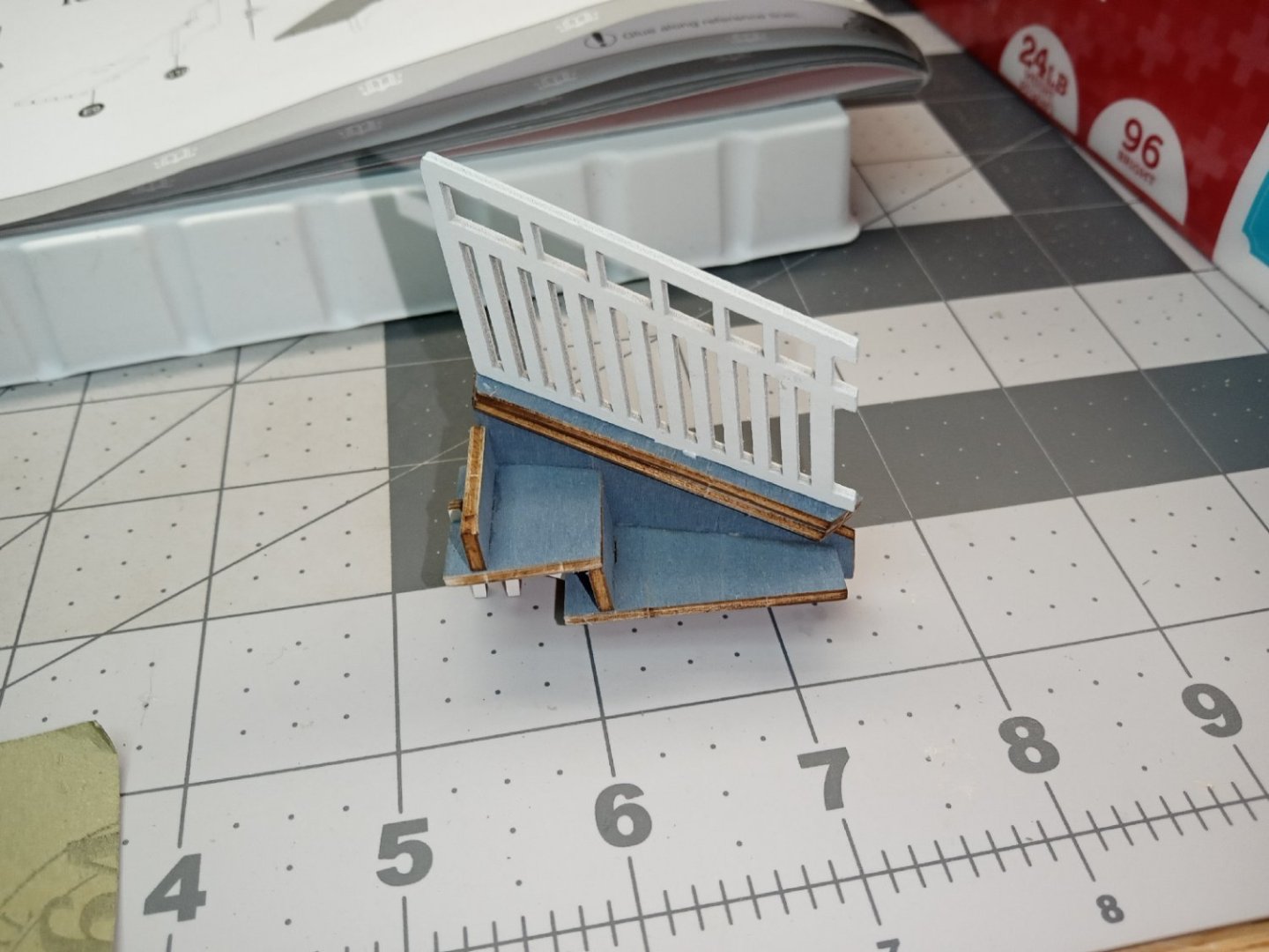
This photograph shows the finished wall/step section. One mistake I made was trying to install the railing tab into the top sill piece, before gluing both into the lower sill. The pressure broke the sill piece. I pulled the sill piece off, glued it to the lower one, and then pushed the railing tab into place. The railing tab extends into the lower sill and locks the two sill pieces into alignment. Before the glue set, I made sure the sills were lined up evenly to the wall, and the railing sat in line with the sills.
Here is a shot of the inside of the wall assembly.

-
Part_007
This sub-scene is completed, for now, by adding track side details. The railroad crossing guard and the second cherry tree are added. I glued the branch to the tree at this point. Another cherry blossom was also glued on the ground.
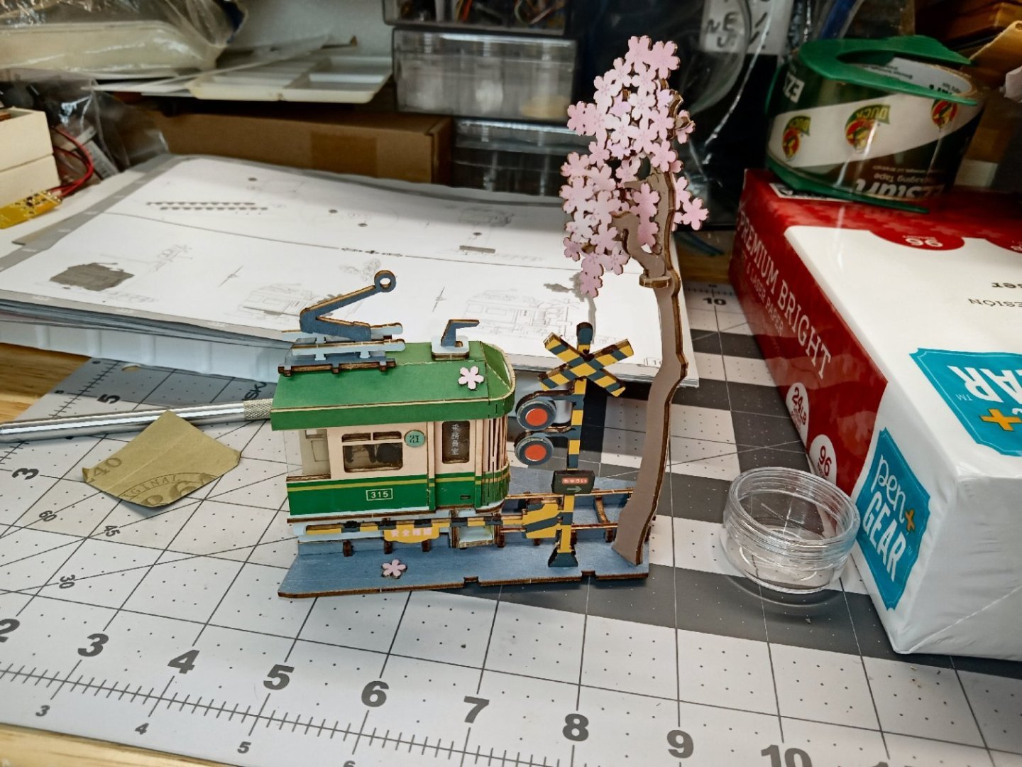
Here is a picture from the back.

The assembly of the base of the diorama is the next step in the build.
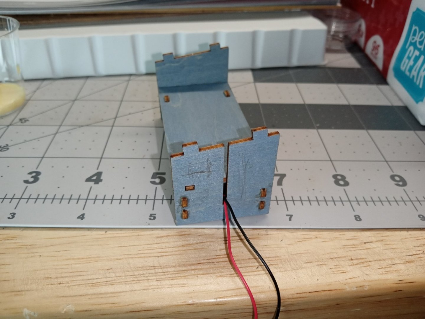
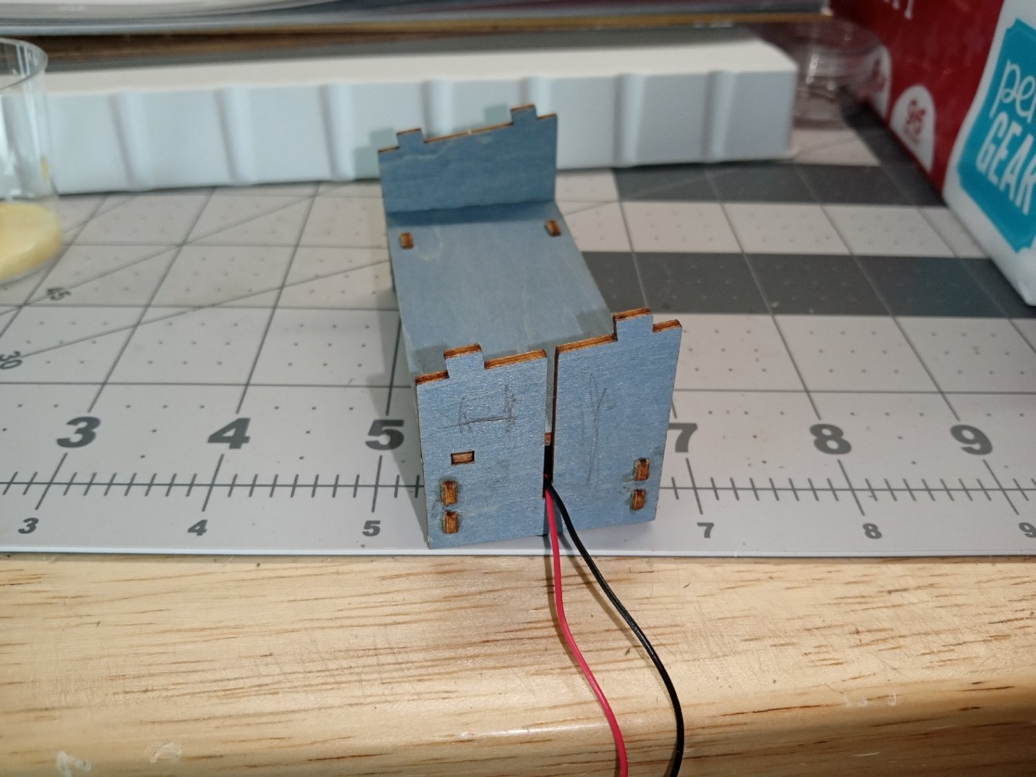
Construction begins with the rear support/battery box. I still plan to build a dedicated power supply for all these Book Nook dioramas, once I have finished them. This will be more difficult than first planned, as they do not all use the same voltage. The first kit used a 4.5V battery pack, and this one uses 3V. On the first kit, I did not permanently attach the pack, which was designed to be through bolted, with the nuts hidden from access when construction was completed. This kit has the pack captured in the base foot compartment, but can be removed from the bottom to install the batteries. I built it this way; I can always cut and extend the wires later.
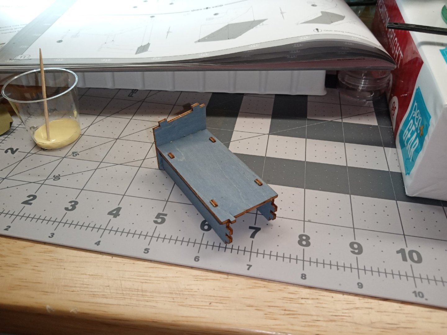
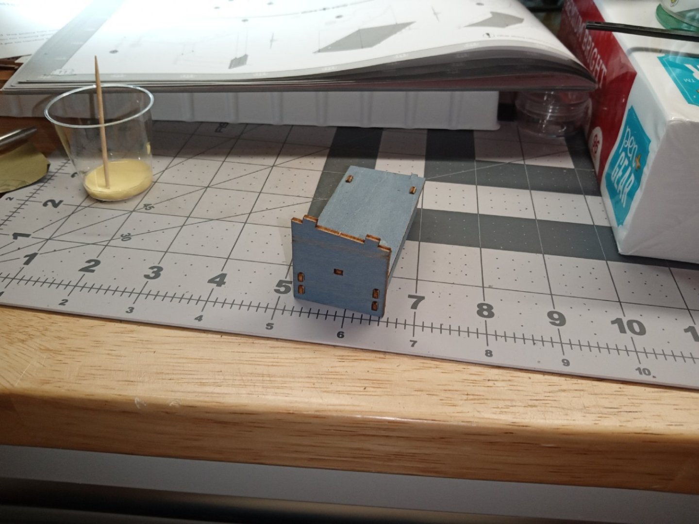
The battery pack holder/rear base support, is the first piece to be built. This is a straight forward box. The only real care that must be taken, is the get the angled tops of the ends oriented correctly.
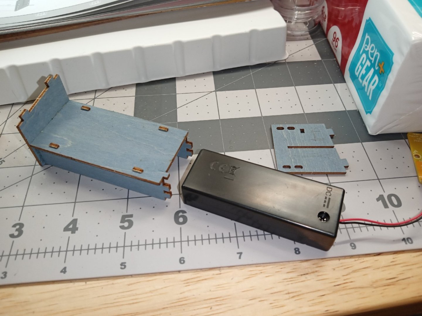
The other end wall is installed with the wires trapped in the slot, and the battery box placed with the On/Off switch at the bottom.
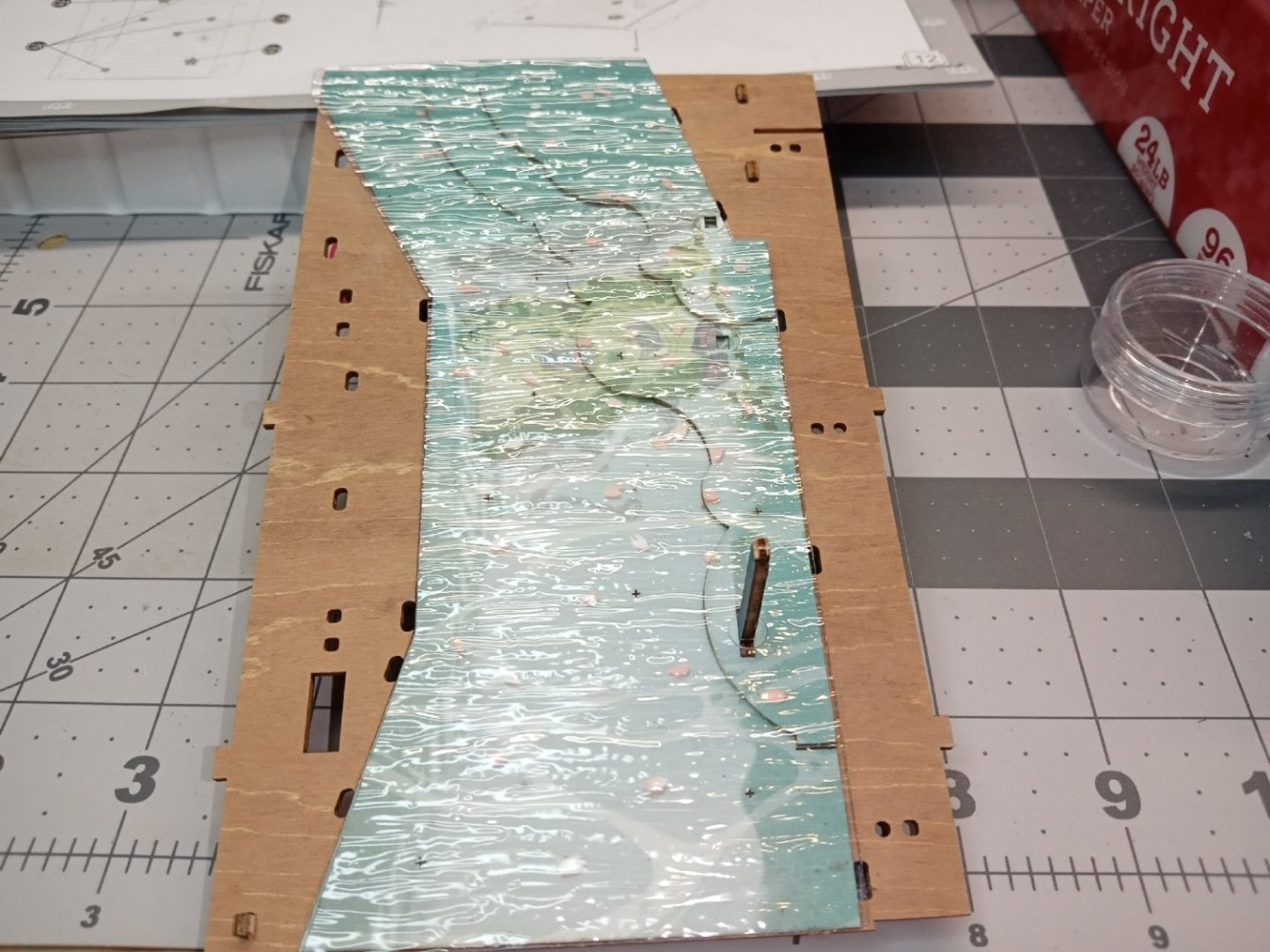
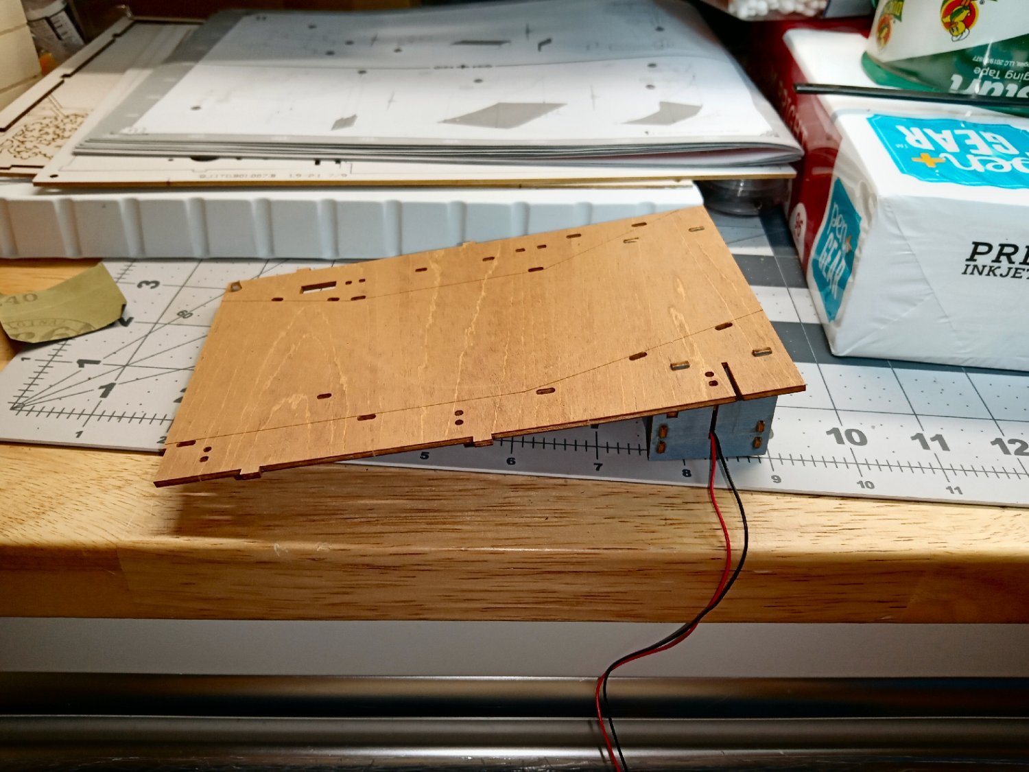
This photo shows the assembled rear base, an angle bracket/foot that is attached at the bottom of the base plate at the front left side, and the base plate that the stream will be built up on. The etched lines running from front to back, outline the streambed.
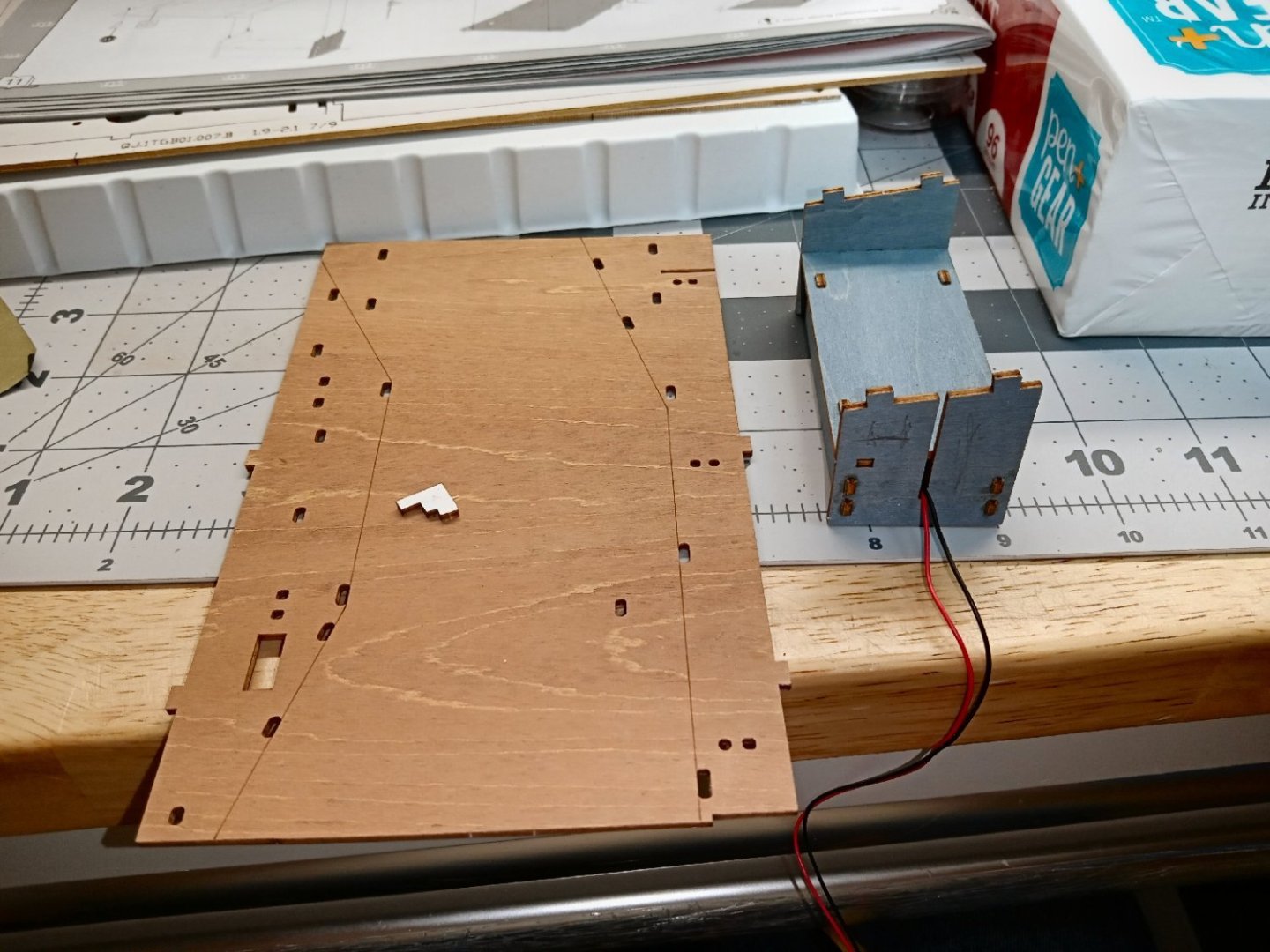
The rear base is glued on first


Next the angle bracket is installed.

The streambed under the clear ripple plastic water sheet, is made from three printed layers. The first layer covers the entire streambed. Two of the rear base tabs stuck up above the surface of the base plate, so I carved and sanded them flush.

I glued the bottom/main colored sheet down, spreading the glue evenly over most of the bottom of the sheet. I then used lots of clamps around the edges of the sheet.
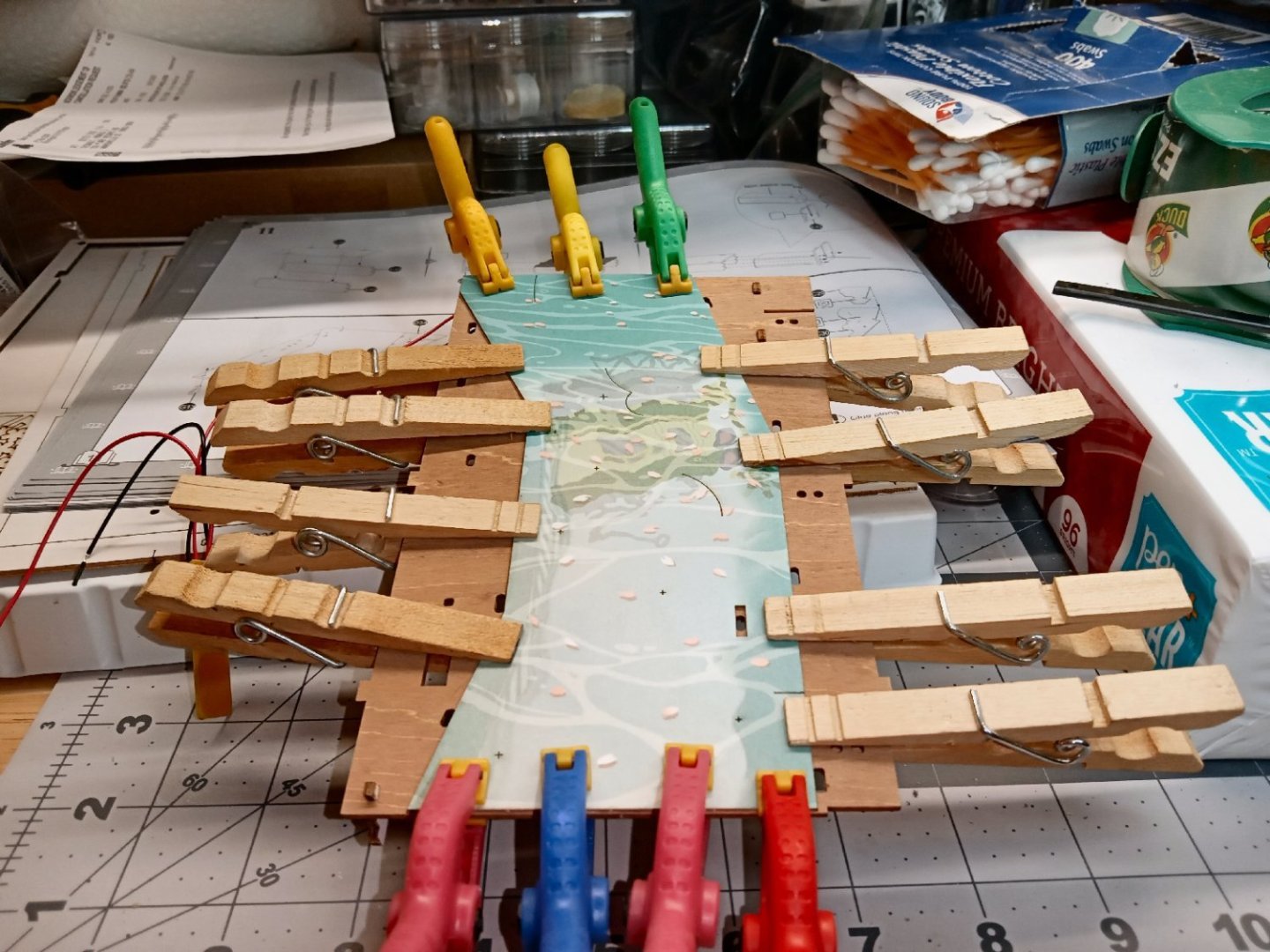
Then I put a couple of weights in the middle. I let this sit over night to dry. The weights did warp the base plate a little, but not badly. I should have supported it from underneath.

This picture shows the pieces for the final two layers.
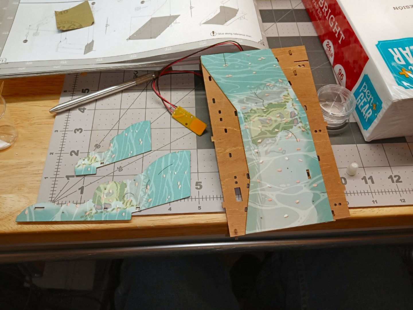
Here they have been glued on, and located by installing a piling.

This picture shows the rippled plastic sheet set in place. As construction continues, other pilings will lock it in place. After the rest of the pieces that install along the shore are installed, I’ll glue the rippled sheet down in a couple of hidden spots. The next step is to glue many different sized “floating” blossoms to the surface of the water. I will wait as long as possible, to glue on the blossoms, to prevent them being knocked off as building progresses. The location of each blossom is marked by a small cross etched in the stream bed. The instructions also show the locations, as well as showing the part numbers of the various sized blossoms.
-
Part_006
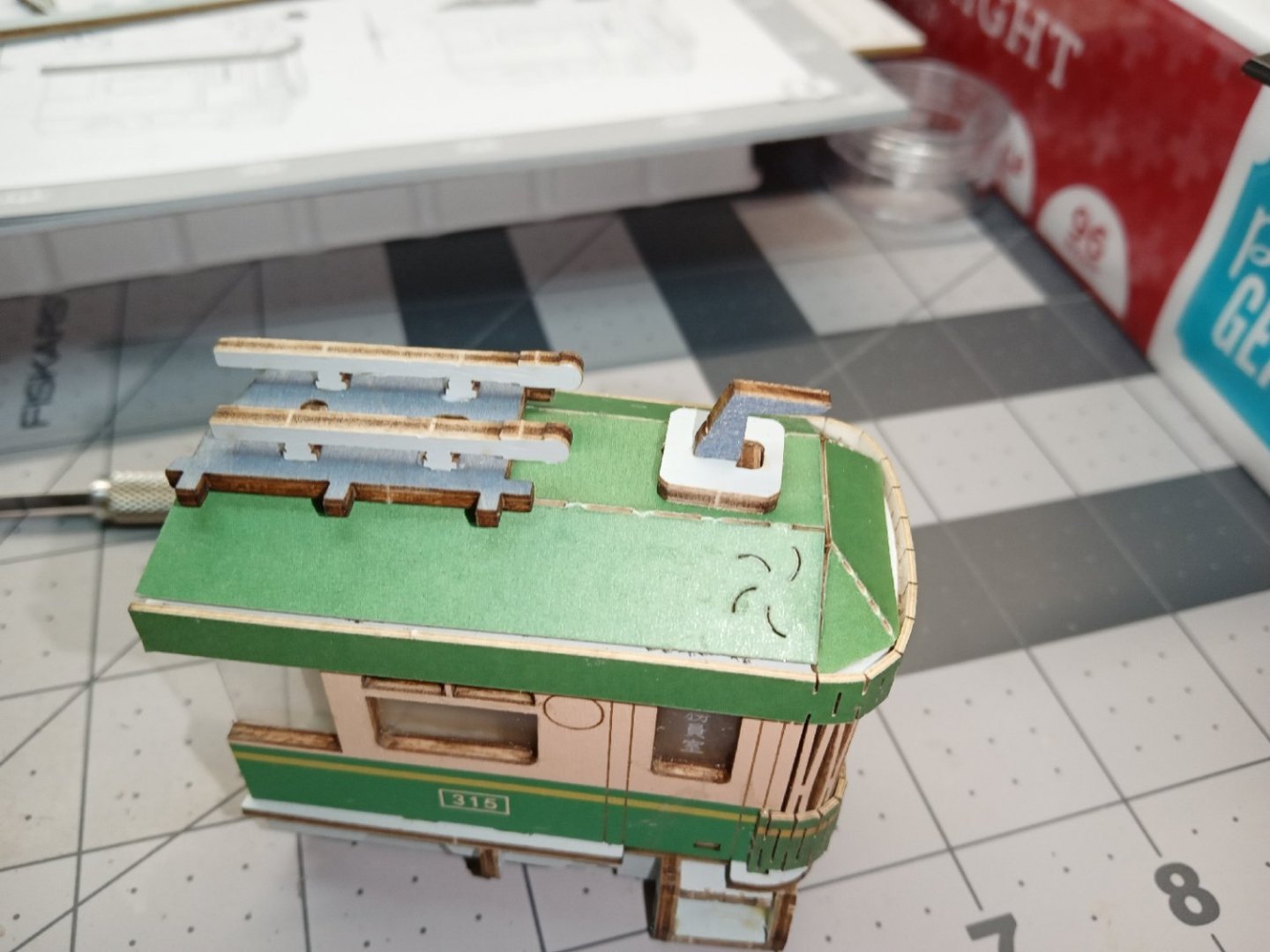
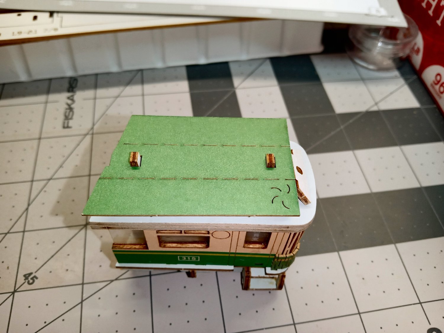
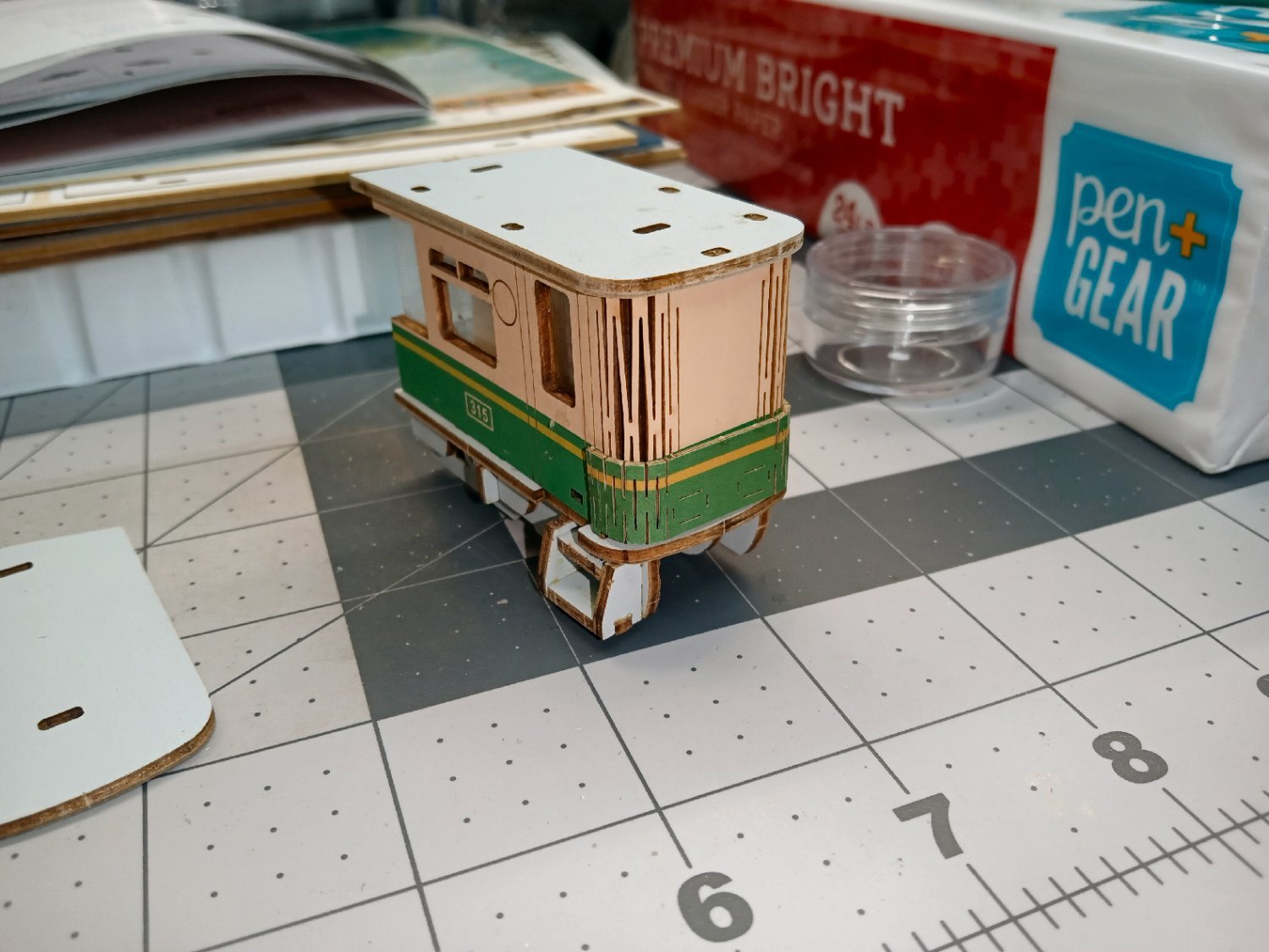
Next, the exterior roof pieces are installed. First the main roof piece is installed. After gluing the center section, it is to be bent down along the slotted seams. Here is where I found a surprise! These pieces are not cardstock, but a lamination of two paper covers over some type of thin wood sheet! I went to bend the two sides down, and they resisted my gentle efforts. After I applied more pressure, the sides bent down with barely audible cracking sounds

I applied some glue to the angled subframe sections, and held the leaves down until it grabbed. Because of the many-colored surfaces, I’ve been using mostly the clear Canopy Glue for the construction.
An angled front roof piece is attached, next. This one also is bent down, once the center area is glued on. To ensure that these parts stayed in place, I ran a line of glue along the bottom edges of both parts, and a little in the seams between the main and front sections.

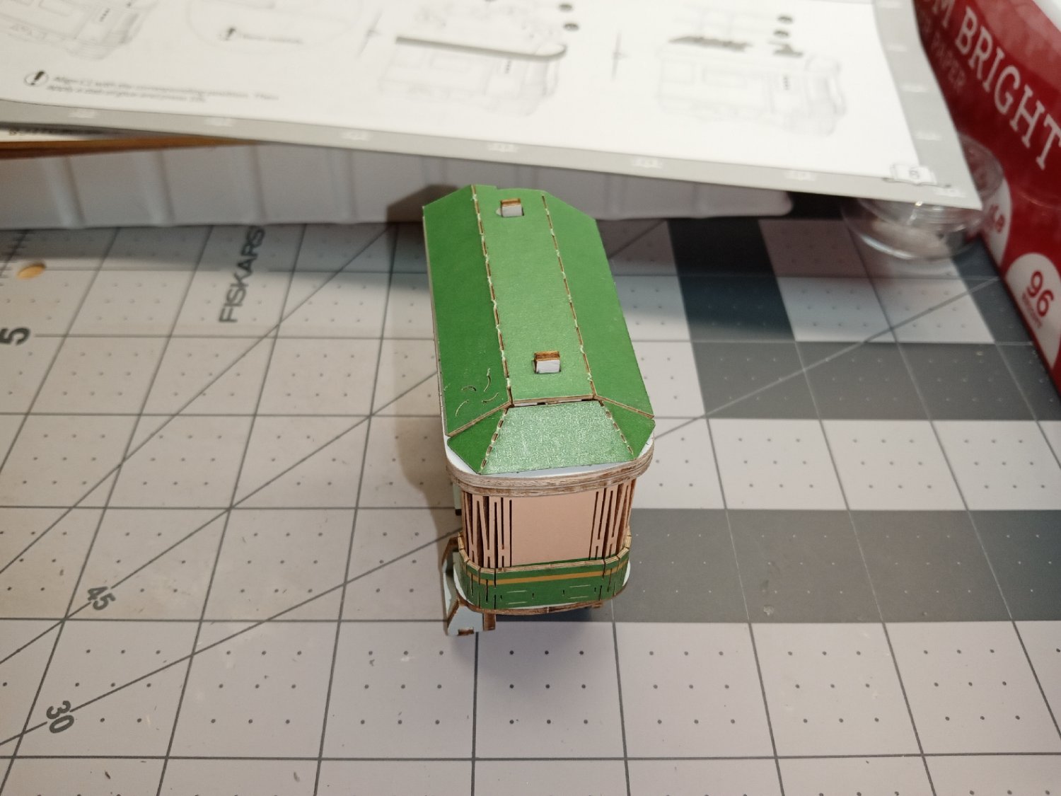
I sanded the edges of the two top roof subframes smooth and even, in preparation to the next step.
There is a long thin rim that needs to be glued along the length of this edge. The part is also slitted to bend around the corners, and follow the curved front of the roof. I had to carefully align the ends of the trim piece with the rear edges of the roof subframes, with the bottom edge even with the bottom of the roof subframes, and flat along the curved front edge. Quite a task to do before the glue hardened too much! Yes, you more skilled modelers are allowed to laugh, here!

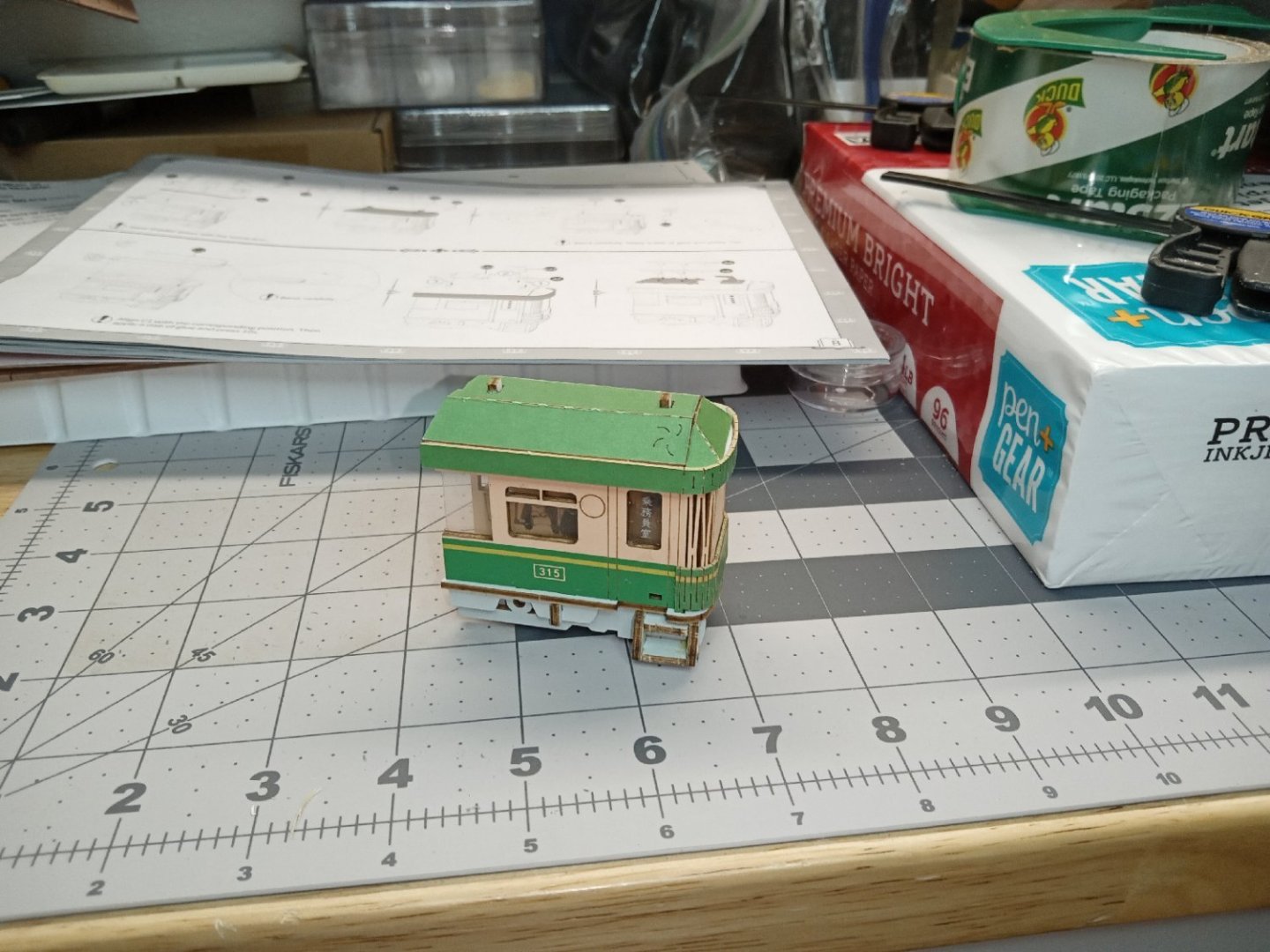
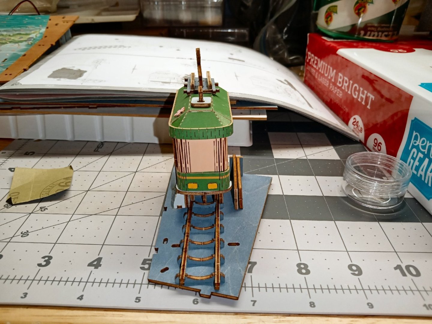
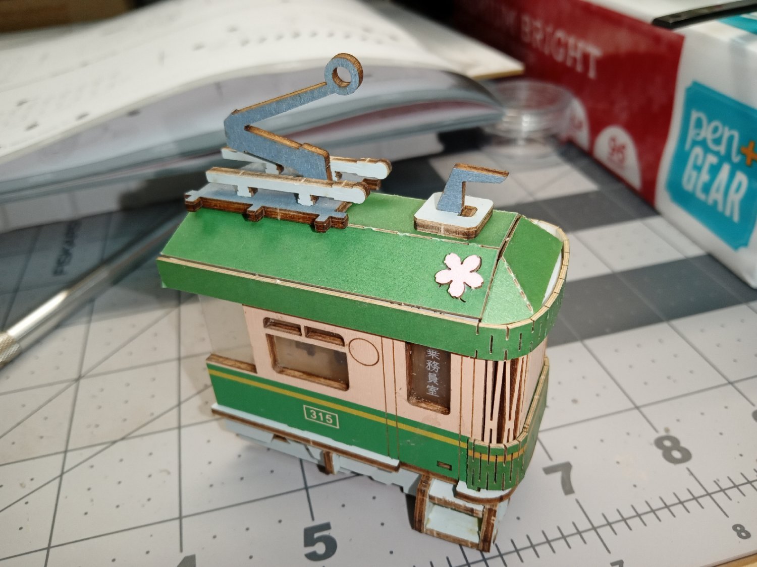
Now the power pantograph and the, I assume, radio antenna parts are assembled on top of the roof.
First the pantograph base and the antenna are installed. The instructions show you the proper positioning of the horizontal parts, as well as a caution to make sure the pantograph base is in line with the roof seams.
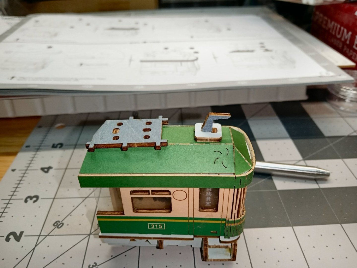
The paragraph parts are now glued on., as well as a cherry blossom that seems to be tenaciously clinging to the roof, of the moving tram!

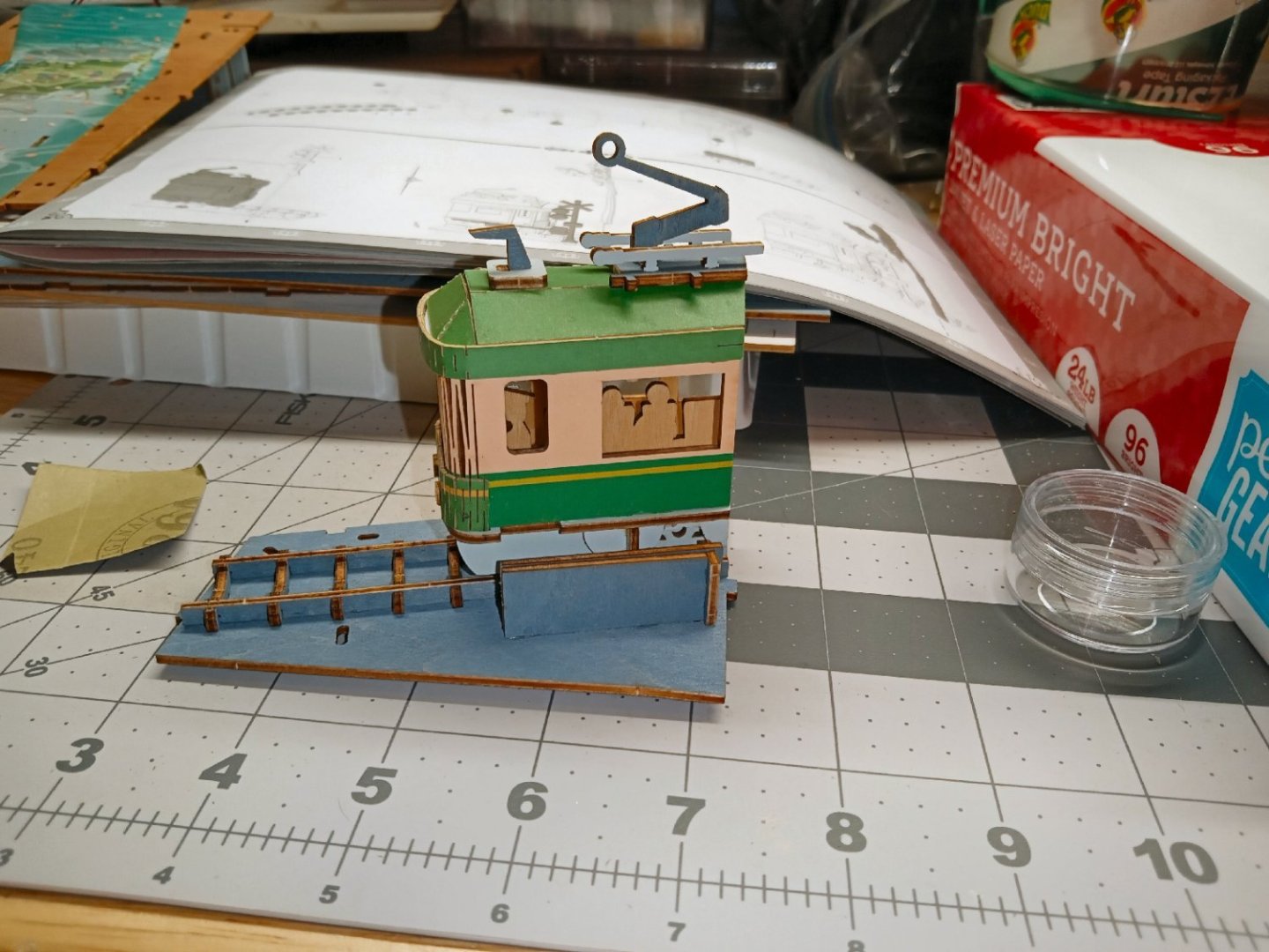
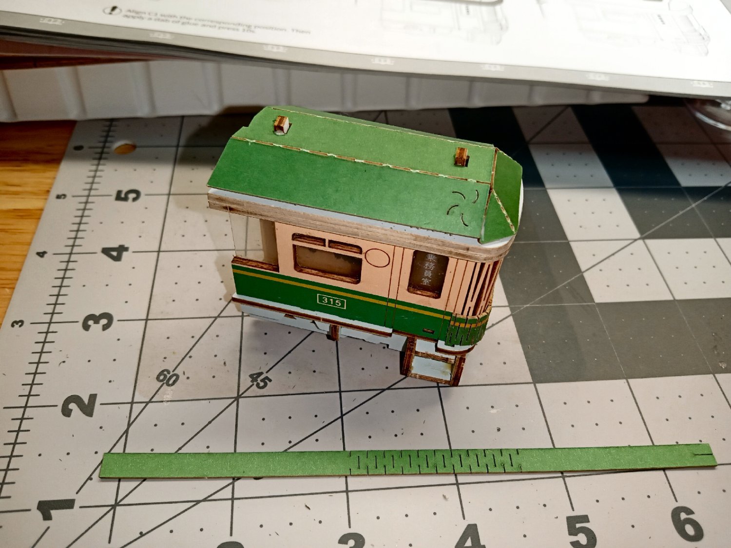
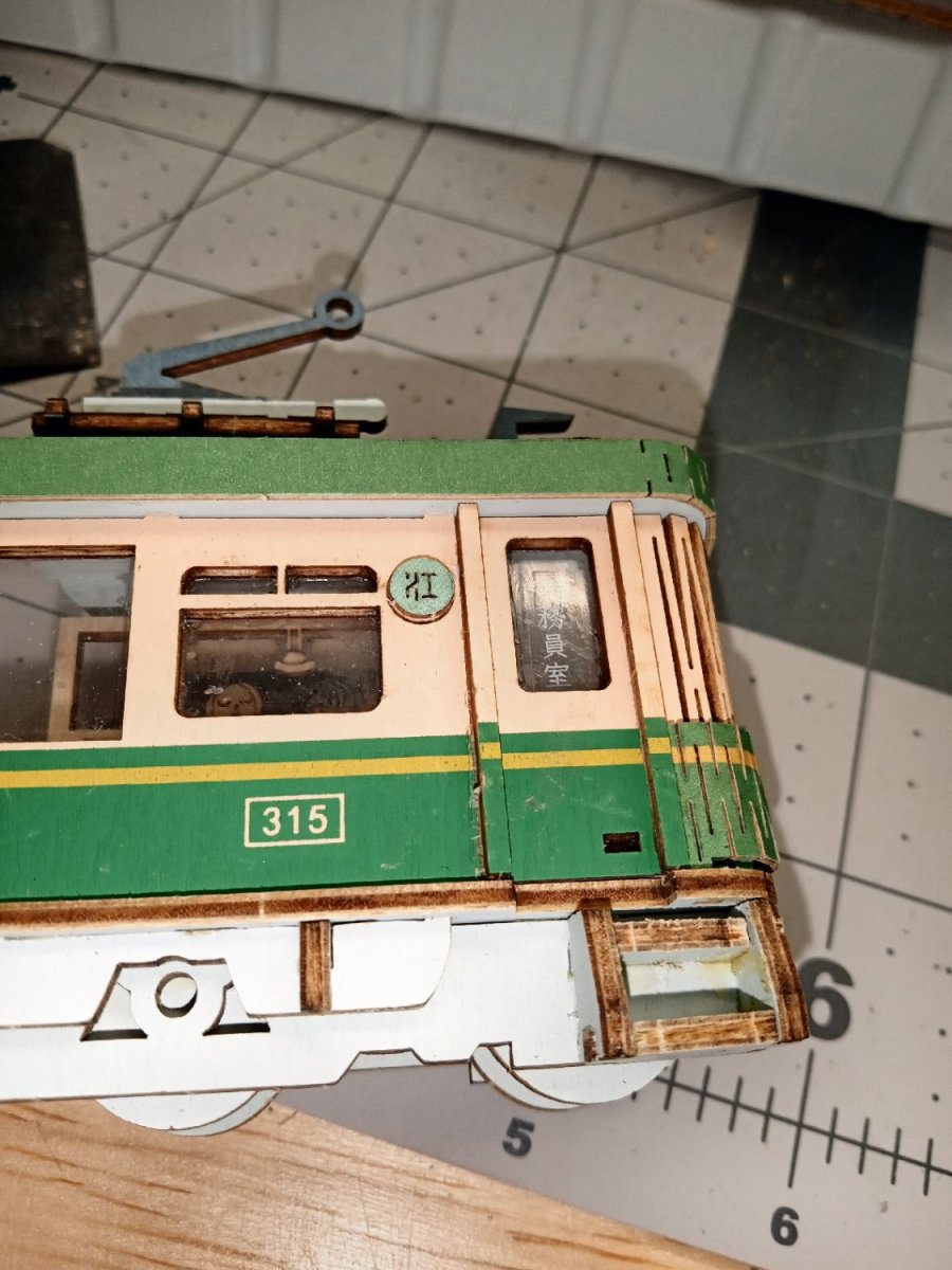
The headlights are installed.
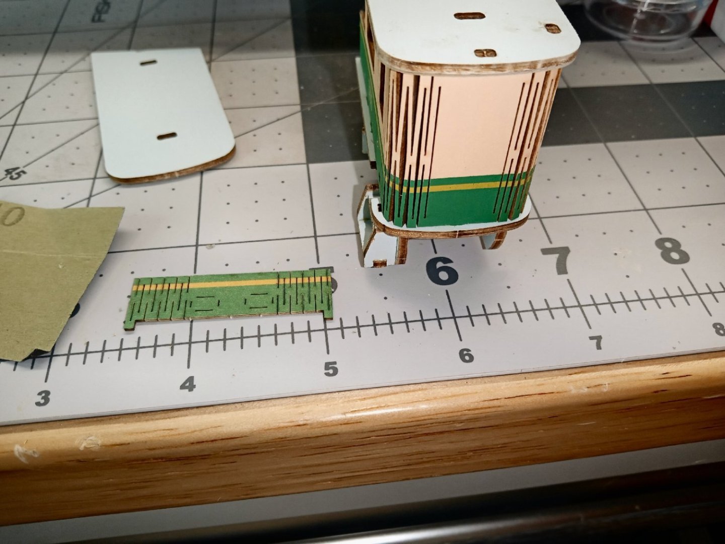
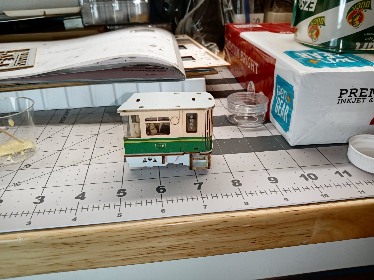
The final part of the tram assembly, is to glue two trim pieces on either side of the engineer’s door, I think to represent the grab bars, and a number plate, next to them.
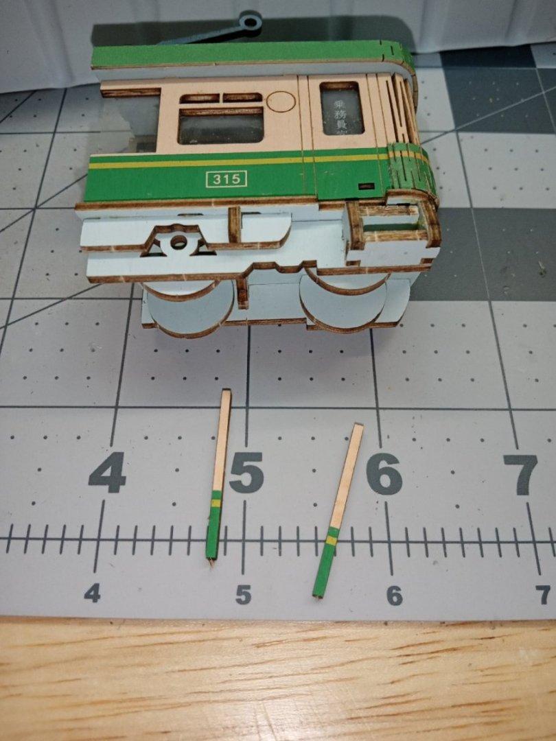

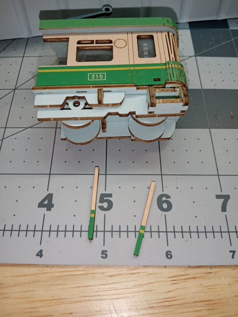
The track base is built next. I didn’t take any pictures of this, sorry. I got into the rhythm of putting it together, and forgot. Both lefthand ends of the rails broke off during the construction. I glued them on separately and sighted down the length of the intact rails to insure they lined up.
There is also some sort of retaining wall behind the rails.
The tram is attached to the base with two stand offs that are glued to the underside. The orientation of these standoffs is detailed in the instructions. If I remember the printed sides of them face the back of the scene.
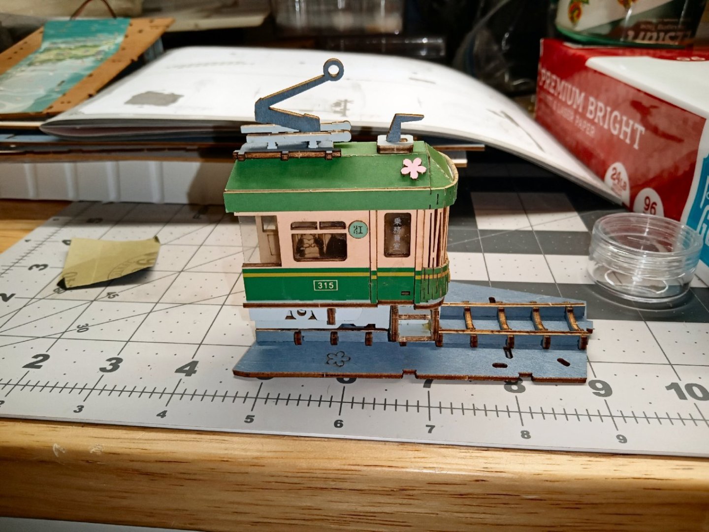
In the picture, below, you can just make out one of the supports, under the headlights.
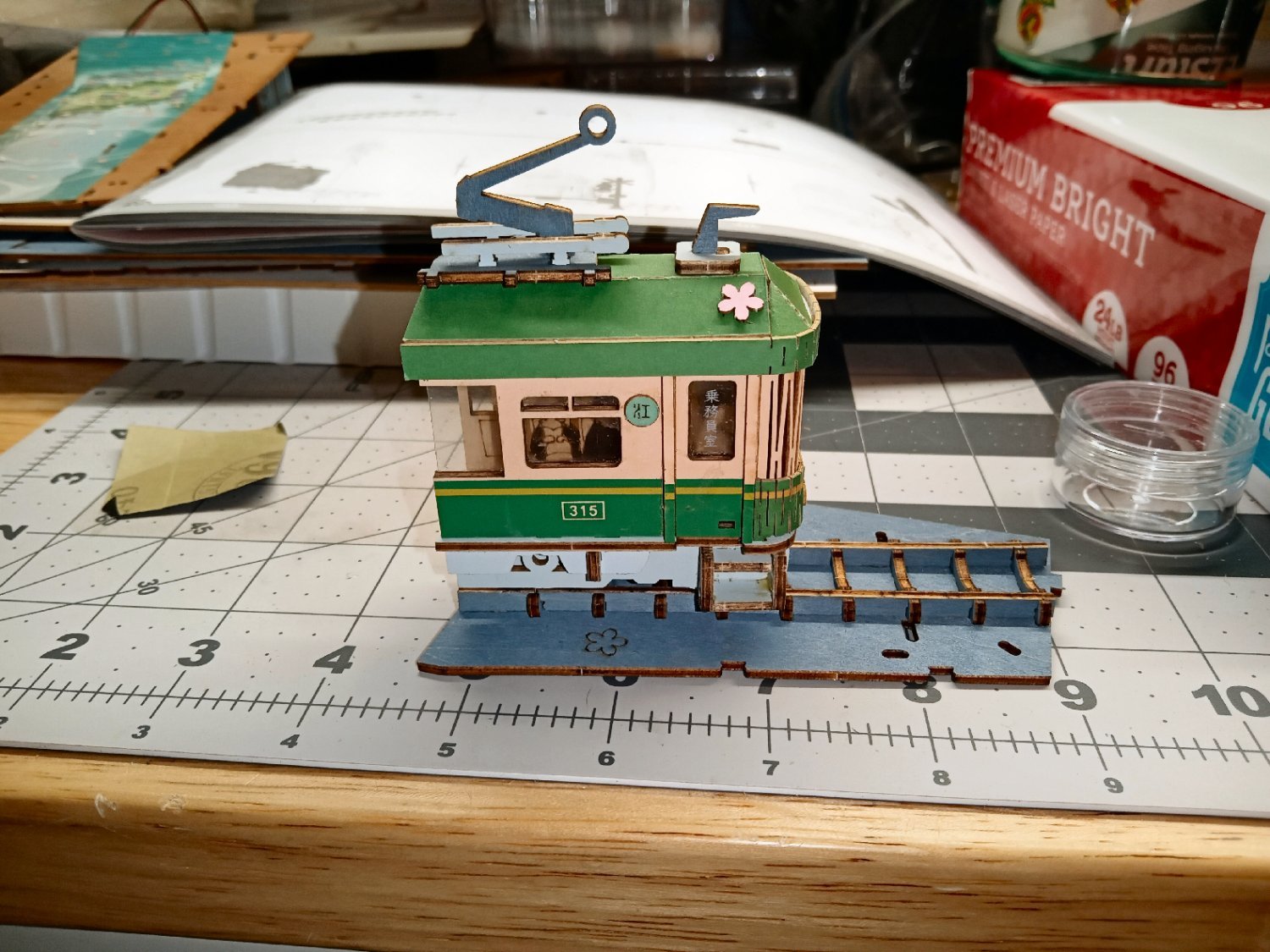
The next part will show the completion of this scene section, and the beginning of the base assembly, with the stream that runs from the back to the front, of the diorama.
- GrandpaPhil, Egilman, king derelict and 2 others
-
5
-
Part_005
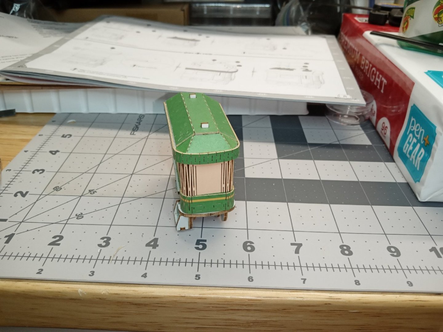
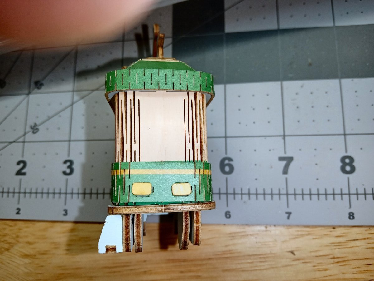
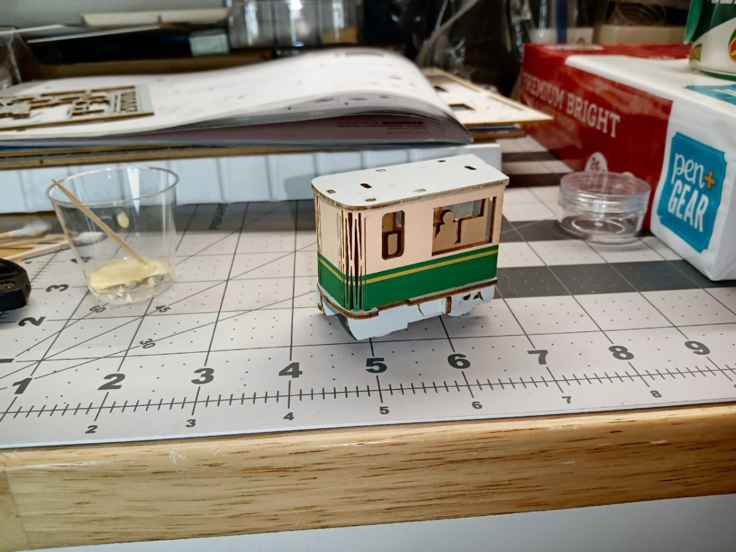
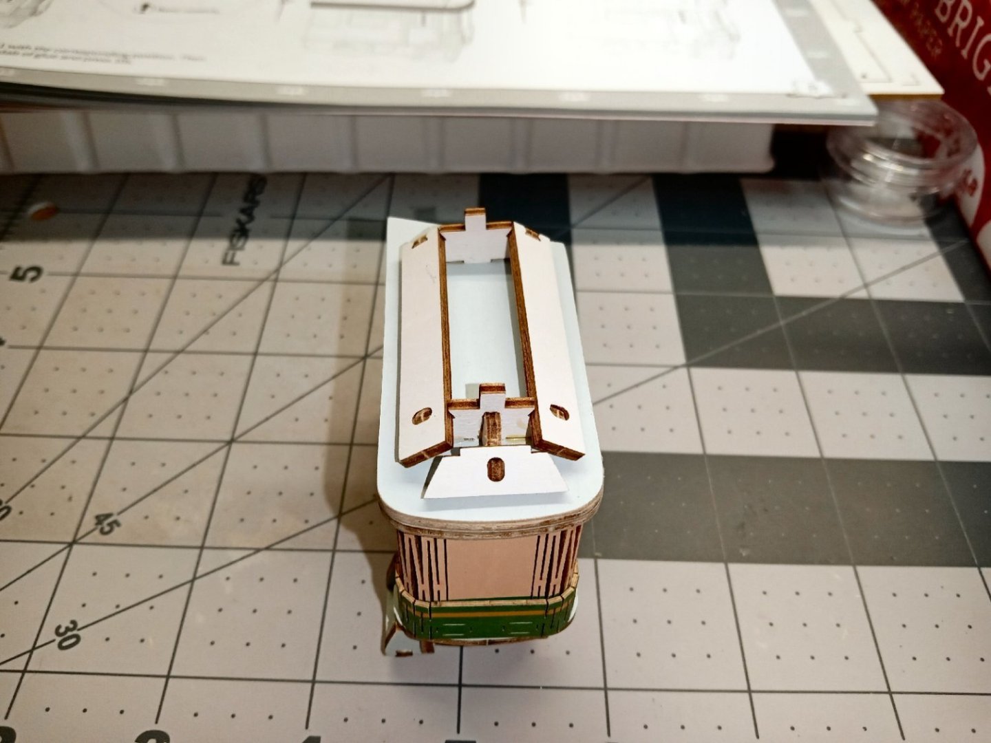
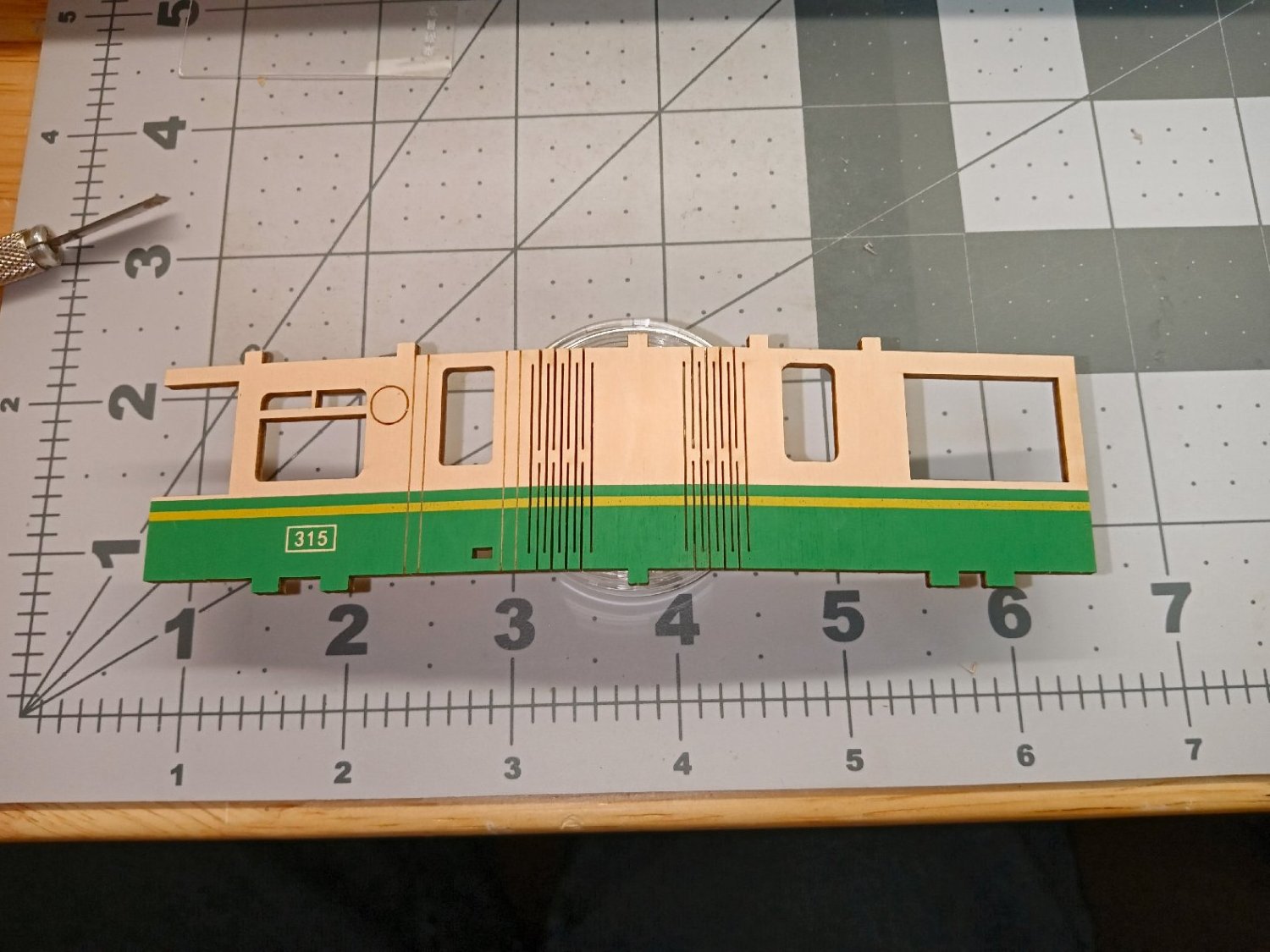
The next step is attaching the tram body, and the first roof layer. You have to do both at this time, in order to stabilize the body walls and insure everything is square. Once again, the unprinted side of the roof is place at the top. In the pictures you can see the slits that allow the corners to curve. The etched circle and two vertical lines on either side of the door, are location marks for details that are attached later. The rectangular cutout at the bottom right of the door, represents the door handle. I did not glue the roof to the body at this time. Later, when the next layer is installed, I glued all the roof assemblies to each other and the body.

The tram windshield is solid in this model, but is not visible from the front viewing angle of the display.


The next step is to install the front trim piece. This is also slotted to fit around the front corners. The rectangular outlines are where two headlights will be attached later.
I had to realign this piece, as when fully seated against the base, the printed strip did not lineup with the one printed on the body. The slight gap is not noticeable from a viewing distance.


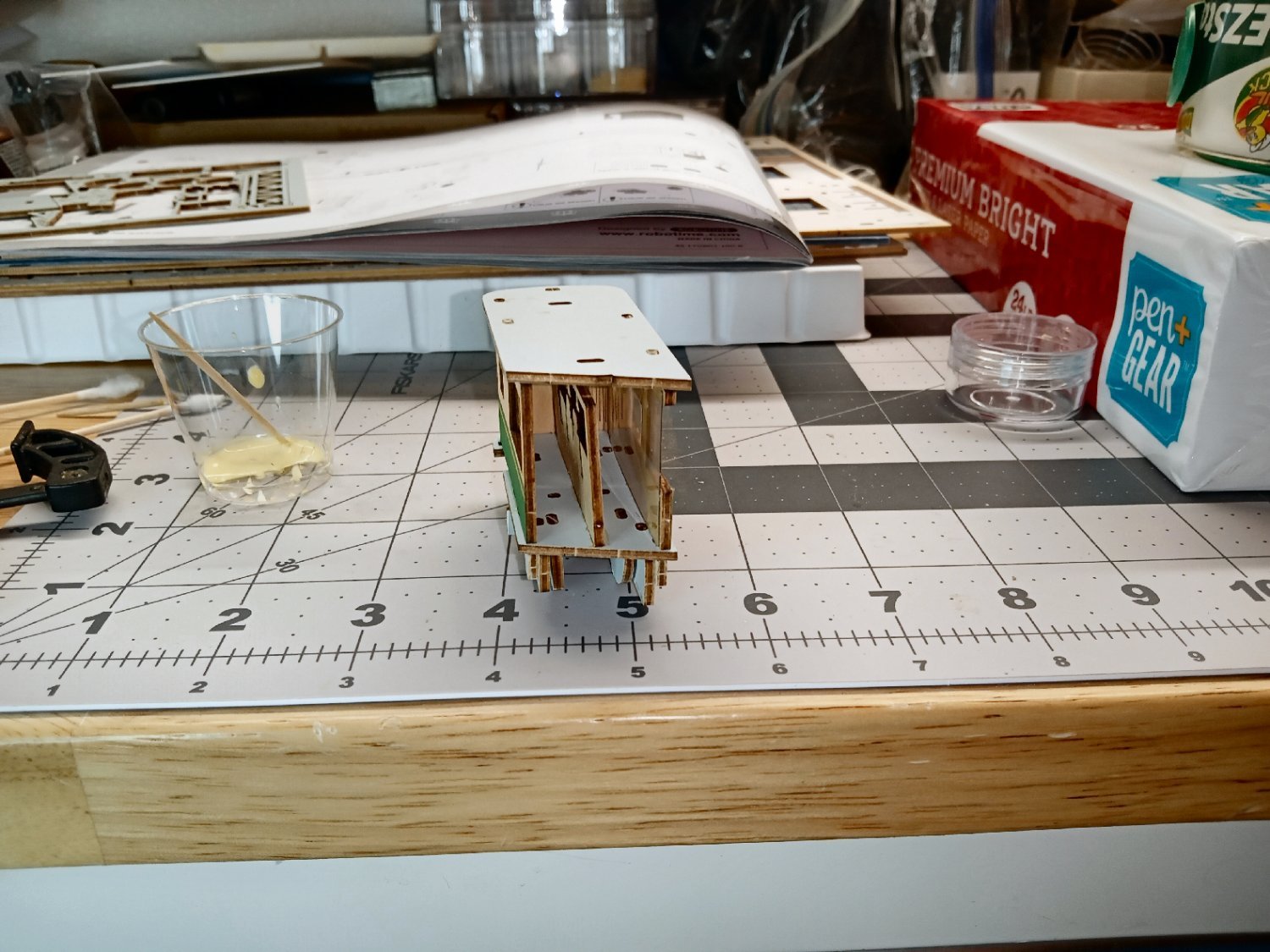
There is a second layer of roof to be added. This part is where the substructure of the roof proper is built. Again, it is placed printed side down.

The subframe is now installed. The tabs on the front and back supports are extra-long to fit into matching slots in the lower section.

After the first part of the substructure is finished, the roof assemblies are mounted and glued to the body. In order to get the parts to mount flush, I had to clamp the assemblies, and let them sit overnight.
This is a picture of the tram to this point, after the clamps were removed. Also shown are the next sub frame parts to go on.
In the next section the visible roof parts will be installed, and a surprise will be revealed.
- mtaylor, yvesvidal, king derelict and 7 others
-
10
-
Part_004
The next part to assemble is another cherry tree. This is also a multi-layer assembly. This one has a branch sticking out of it at a right angle from the main trunk.
The tree and branch are two layers, the printed wood side, and a printed cardstock back. The side with the hole in the trunk is the front.
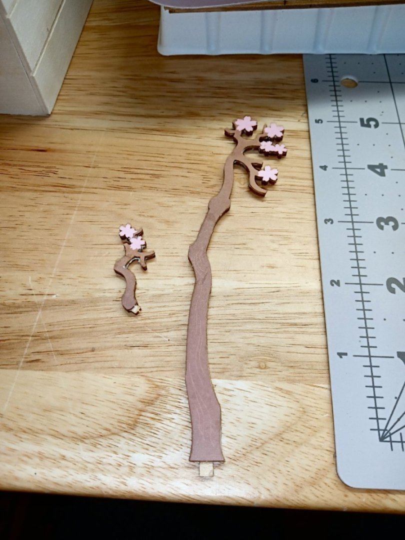

Here are the tree and branch with the multi-layer blossoms attached. I’m not going to glue the branch on, until it is time to mount the whole tree into the scene.

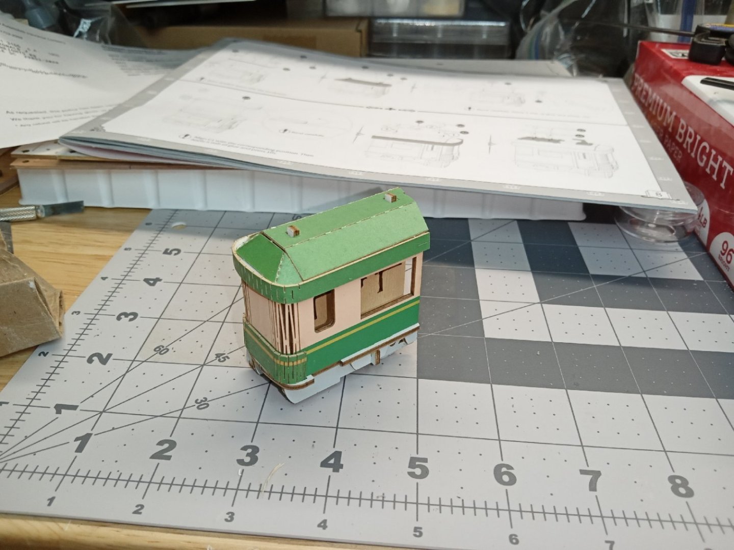
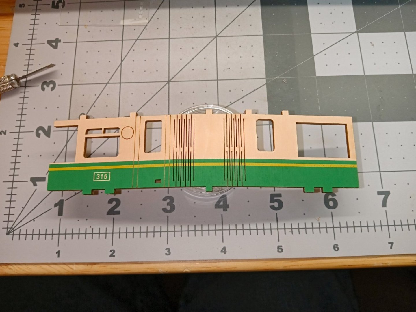
Now starts the building of the tram car. Unlike the last diorama, the body of the car is made from one piece, not several. The body has several slits cut into the corners so that it can bend around the corners.
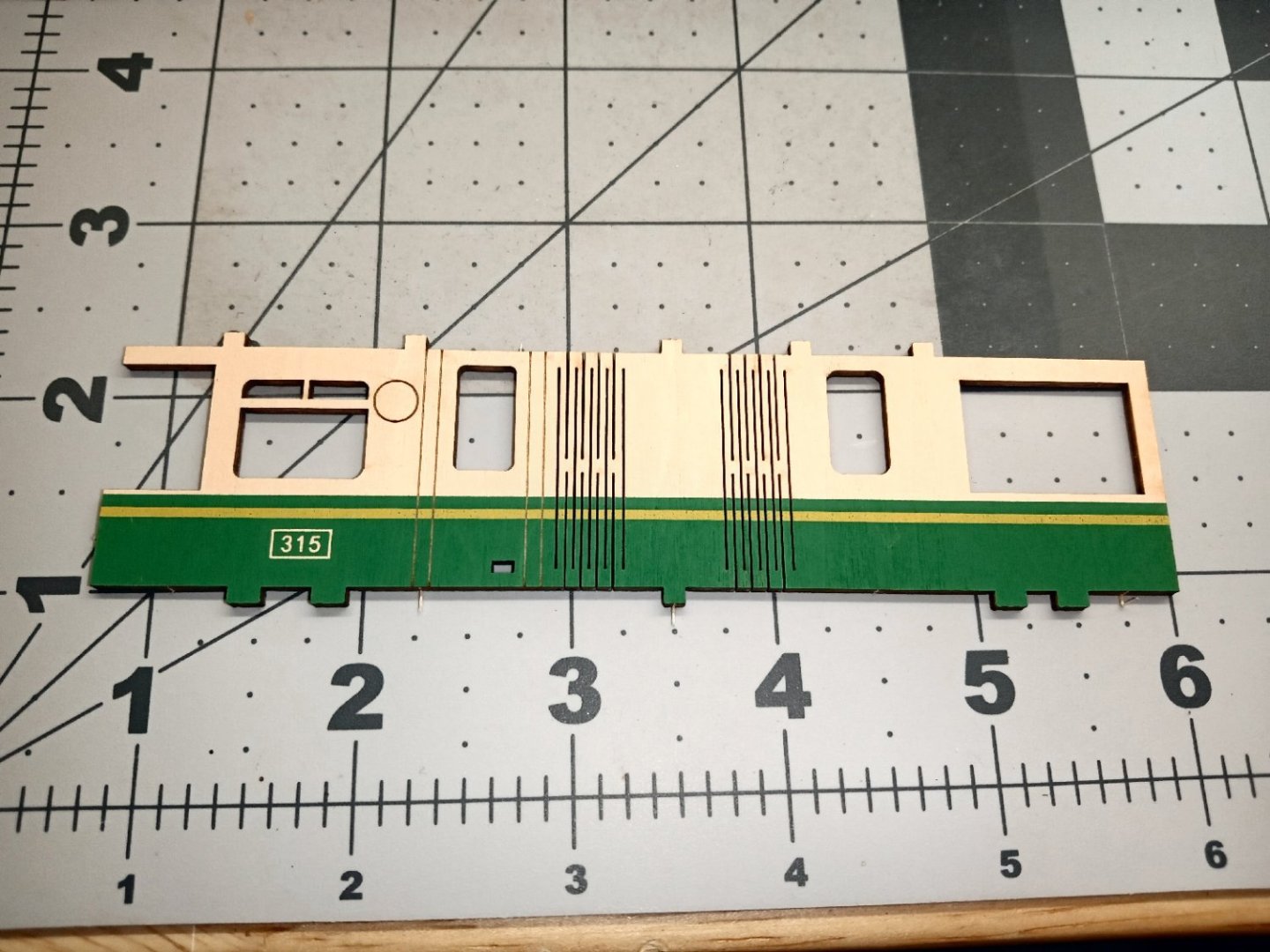
This picture shows the body suspended over a parts box, to show the slits bending in a gentle curve.
This model has clear plastic windows on the front side. I attached the window material with the canopy glue. After it grabbed, I went back with wet Q-Tip’s to clean off the excess overflow, from the “glass” surfaces.
The underframe is the next part to be built. Notice in the picture below that the “Unprinted” side goes up. Both sides are colored, but the part number ID is etched on the printed side, so that goes down.

Next the frame pieces are attached.
Next the wheels are glued on.

Lastly for this section, the steps. It was only later that I noticed that they are slotted too far forward. I think this it to clear the railroad crossing arm.

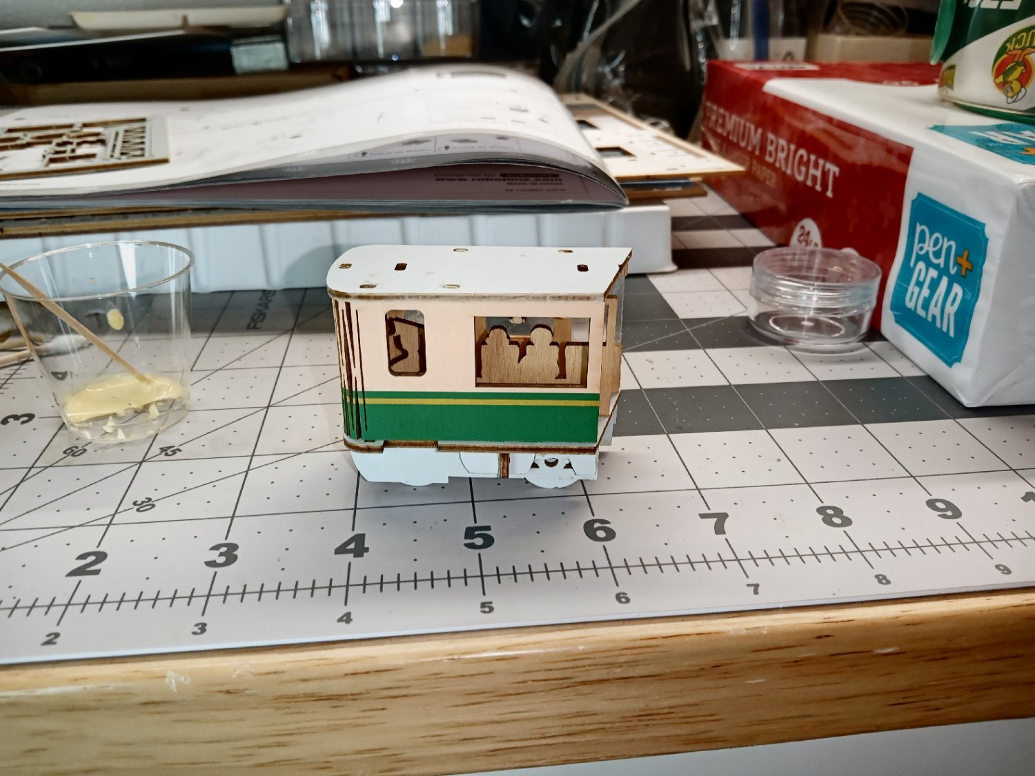
The undercarriage is now flipped upright and the body assembly begone.
First the wall that represents the interior is glued along the mid-line. I used a Sharpie to add some color to the plain wood finish people, supplied for this. I’m not sure why they didn’t print some color unto this but, they didn’t.

- Canute, yvesvidal, Haliburton and 3 others
-
6
-
13 hours ago, modeller_masa said:
I've experienced that excessive CA glue "pond" lasted for a month. It is good to use a limited amount, and the CA applicator helps to control it. I remove CA glue with Q-tips.
Also, thin and fast running CA glue tends to produce more vapor and an eye-hurting smell. It is one of reasons I prefer middle thick CA glue for woodworking.
In addition, CA primer or accelerator harden CA glue in a second.
The accelerators can also mar clear parts.
- Canute, modeller_masa, mtaylor and 1 other
-
4
-
-
I will be continuing this soon. I have been busy with some family problems, which have, finally, been resolved, so less out of town traveling.
- Canute, mtaylor, Old Collingwood and 2 others
-
5
-
On 2/8/2024 at 8:46 AM, Dcox said:
Just to add, there is a product called Mr. Color leveling thinner. It retards the drying time of acrylics so they can flow better which reduces brush strokes. There is a way to DIY the product which is quite cost effective, a simple YT search shows how.
Mr. Color works with alcohol, based acrylics, like Tamiya, and Mr Color, not water based, like Vallejo.
-
On 2/5/2024 at 11:03 PM, Srenner said:
Hi... do you have an stl of a british 18 pounder long gun circa 1720? I can do my own Cypher but just want the basic shape. Thanks
I'm working on that era cannons now, the Bogards 1716. I'm in the process of developing the cypher.
I have the slightly earlier Brown Pattern done. I don't know which your model would have carried.
-
Part_003
The diorama has a railroad crossing gate, and this is the next assembly to be built.
Like the tree, the main body of the crossing gate is a two-layer part. A wooden front and a printed cardstock back. I glued the two together, and the assembly is shown in the two photos below. The upper photo is the front, the other the back. The lower photo also has the rectangular stripped box glued on.
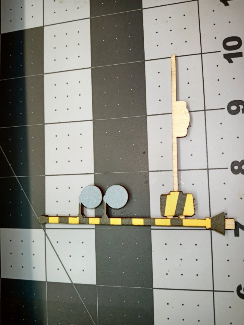
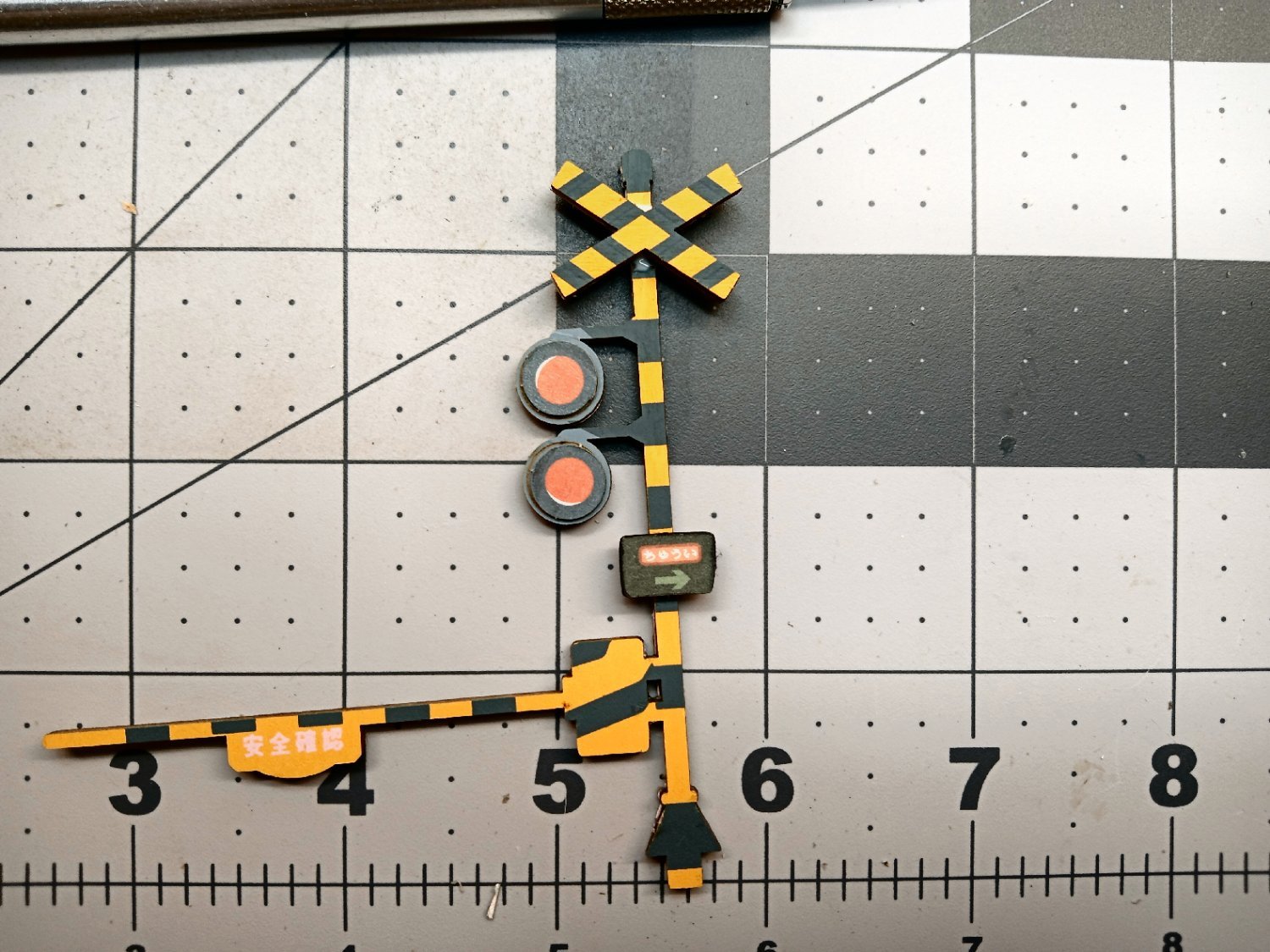
The next part needed, is also a two-part assembly. It is a sign with a directional, I assume traffic, arrow.
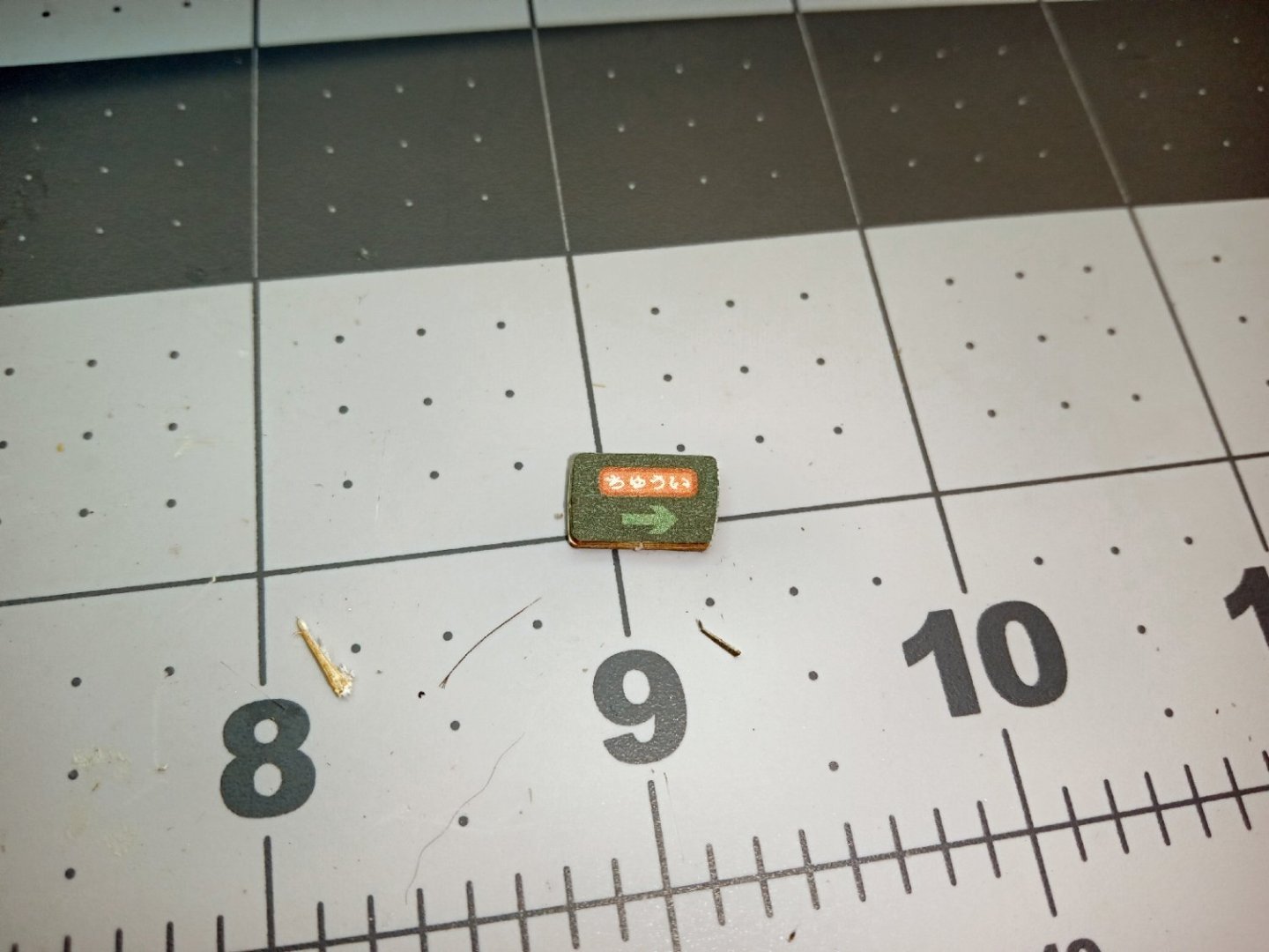
With a mostly black double-sided sign, the raw light-colored edges stood out glaringly. I used a black Sharpie to color the edges.

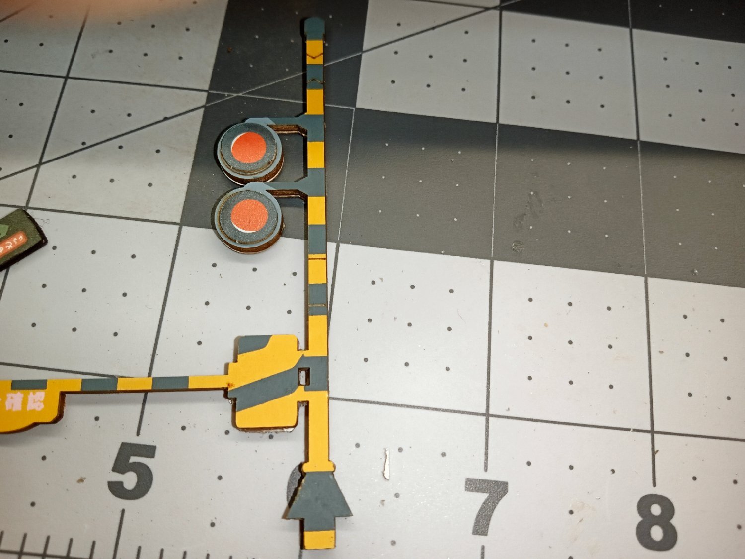
Next the two warning lights are attached. The part has circular outlines to aid in locating them.

Next the two-part crossing arms were glued together, then glued to the pole. There are locating marks for both the crossing arms, as well as for the sign (see arrows).
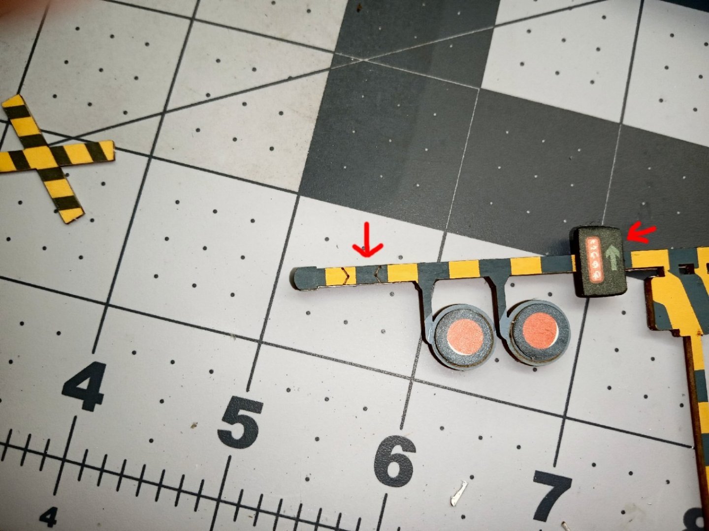
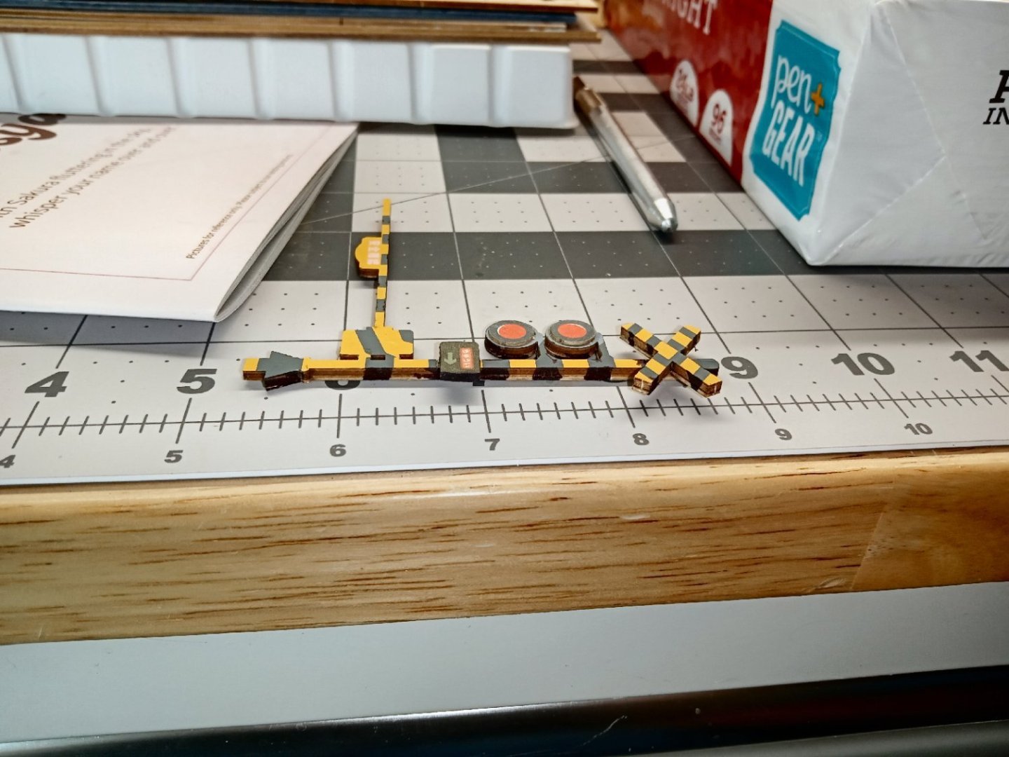
Here is a photo of the completed crossing gate. I did get the two-layer pieces a little off register, so I used a blade to trim then to match, on the edges.
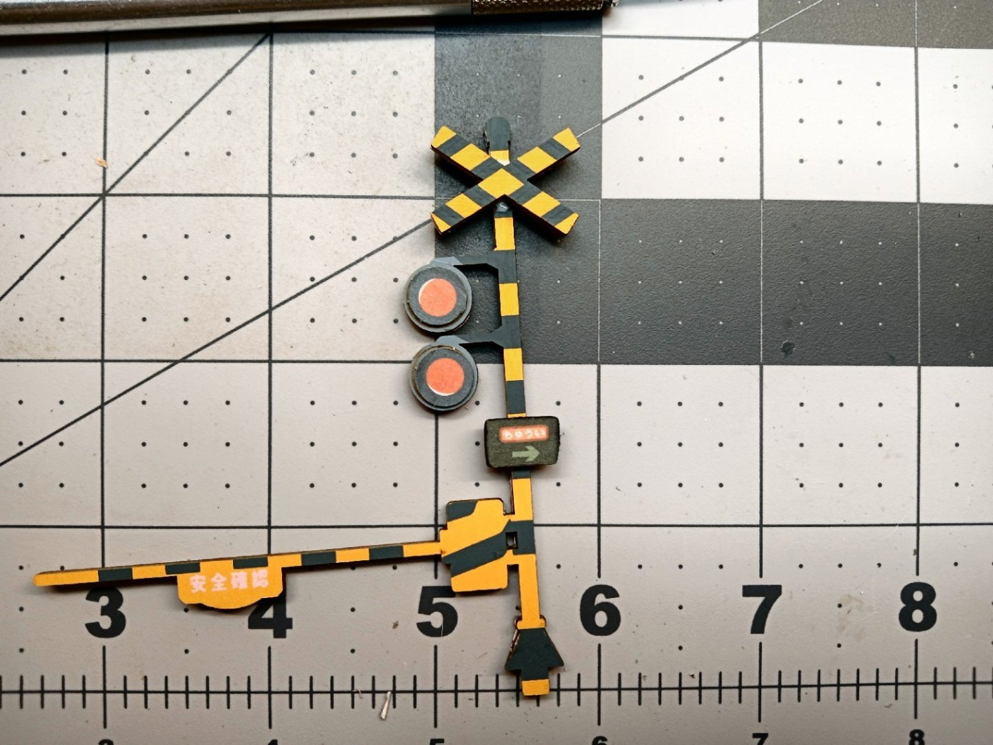
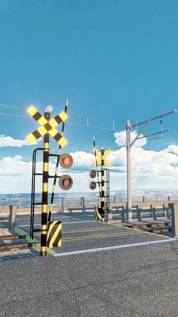
Looking at the picture of an actual Japanese gate, I see that, like in the US, they have shades over the lights. I may fabricate them before I install it.
I used the Sharpie again, to extend the black stripes to the raw sides. With the large tip, it is not the cleanest, but from the distance, will look better than no stripes.


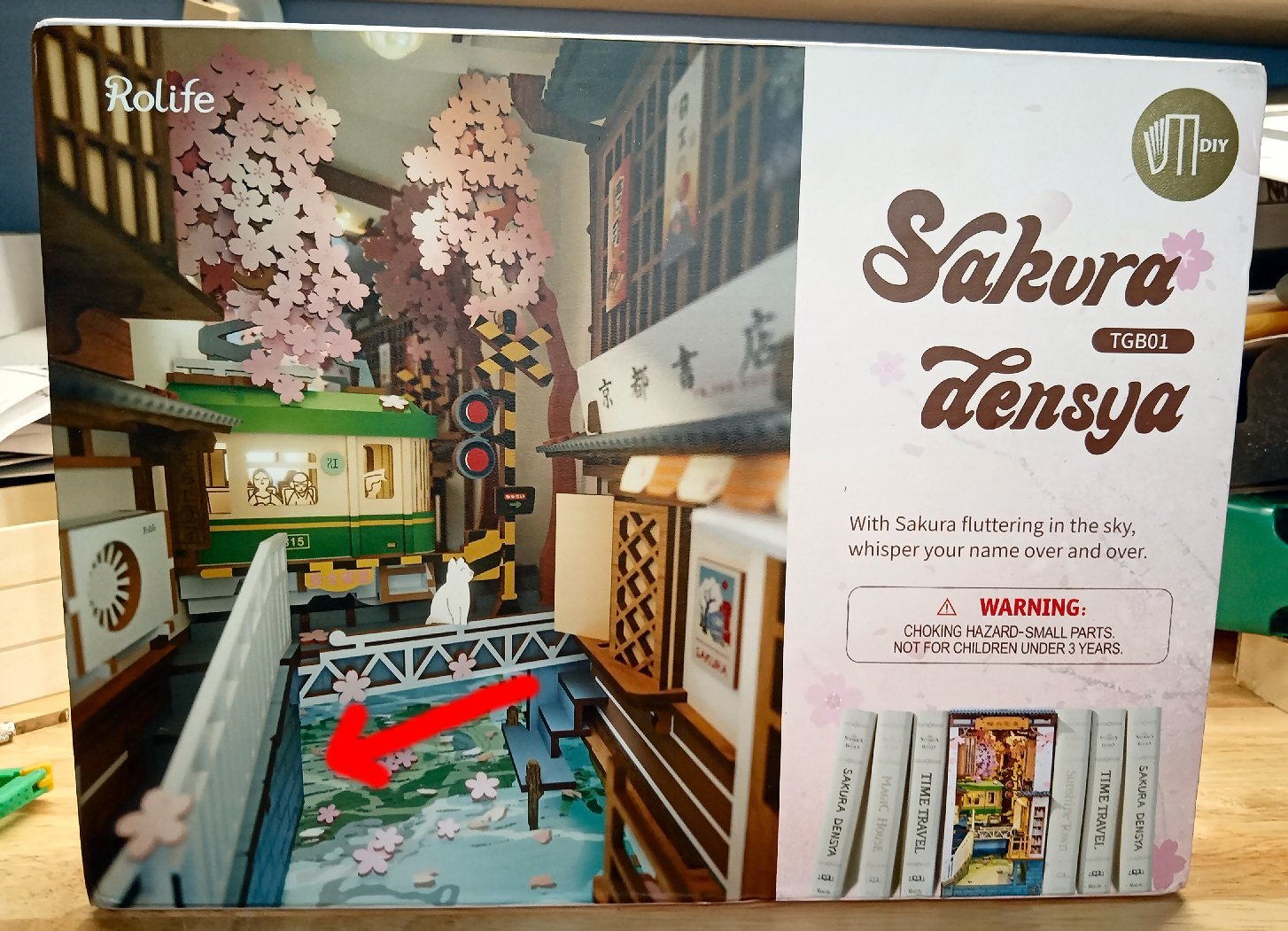


Sakura Densya "Cherry Blossom Train" by thibaultron - Book Size Diorama
in Non-ship/categorised builds
Posted
Sakura Densya “Cherry Blosom Train”
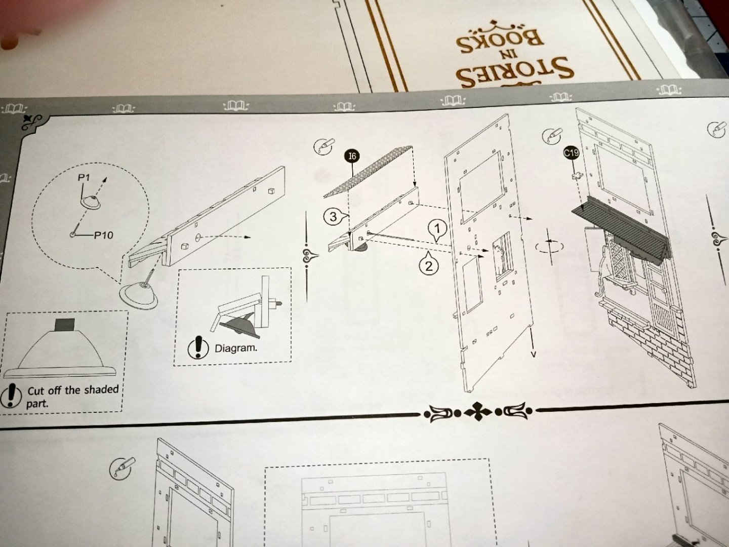
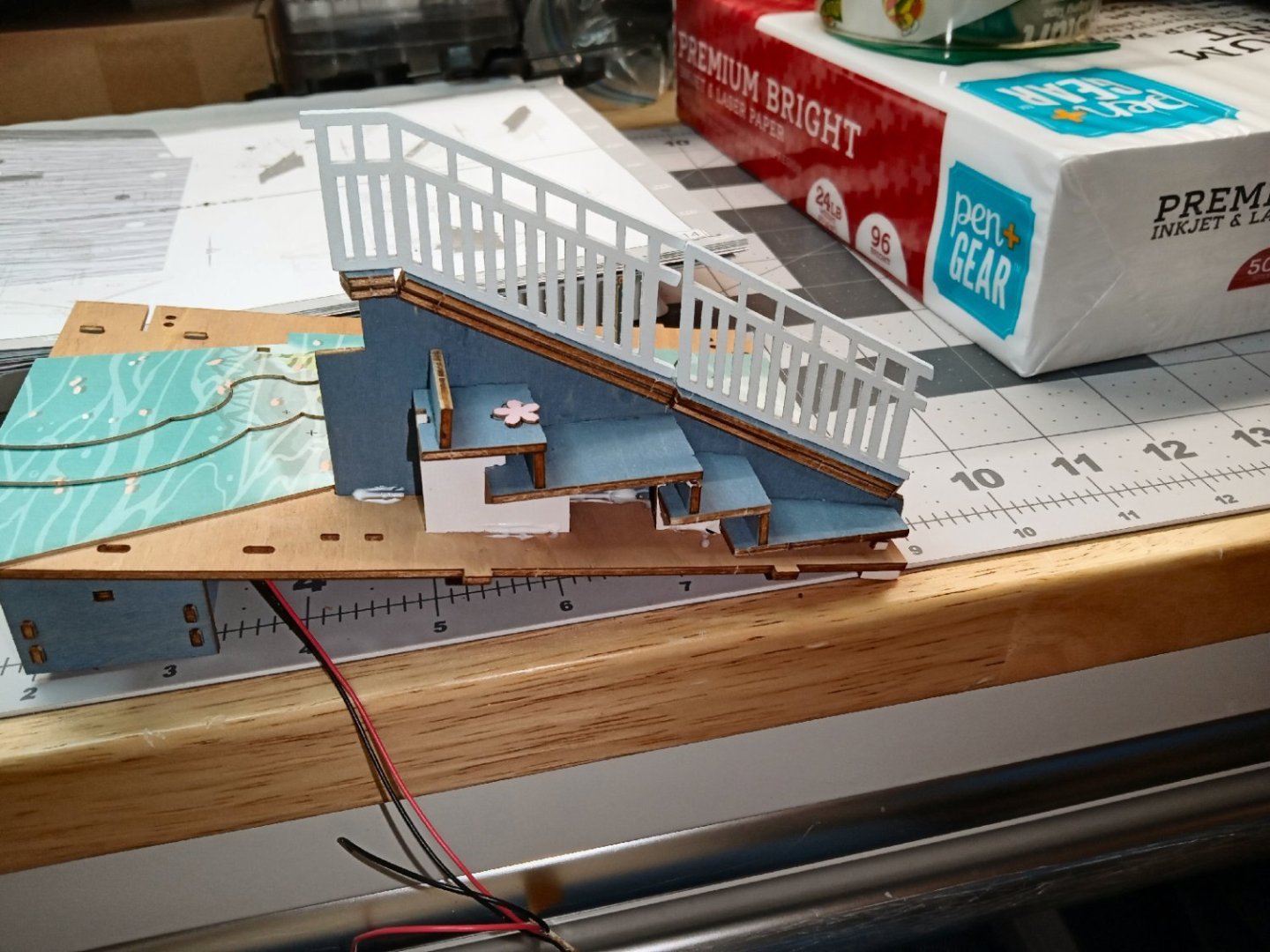
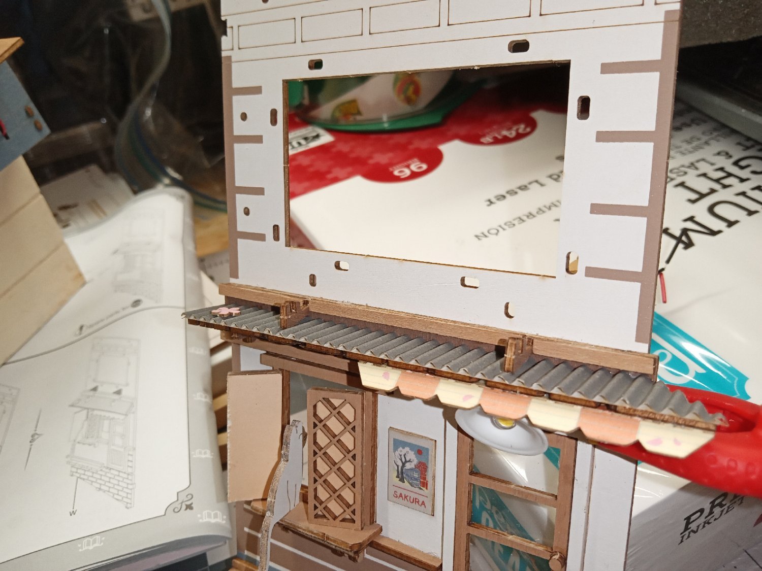
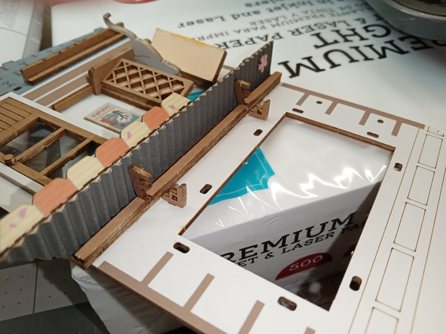
Part_017
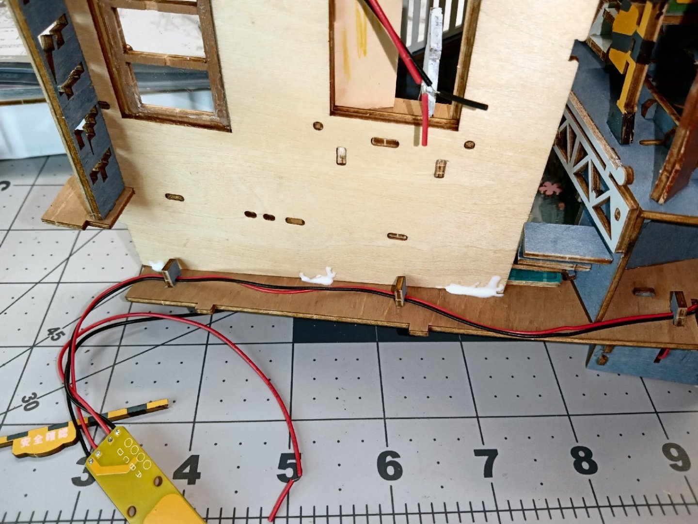
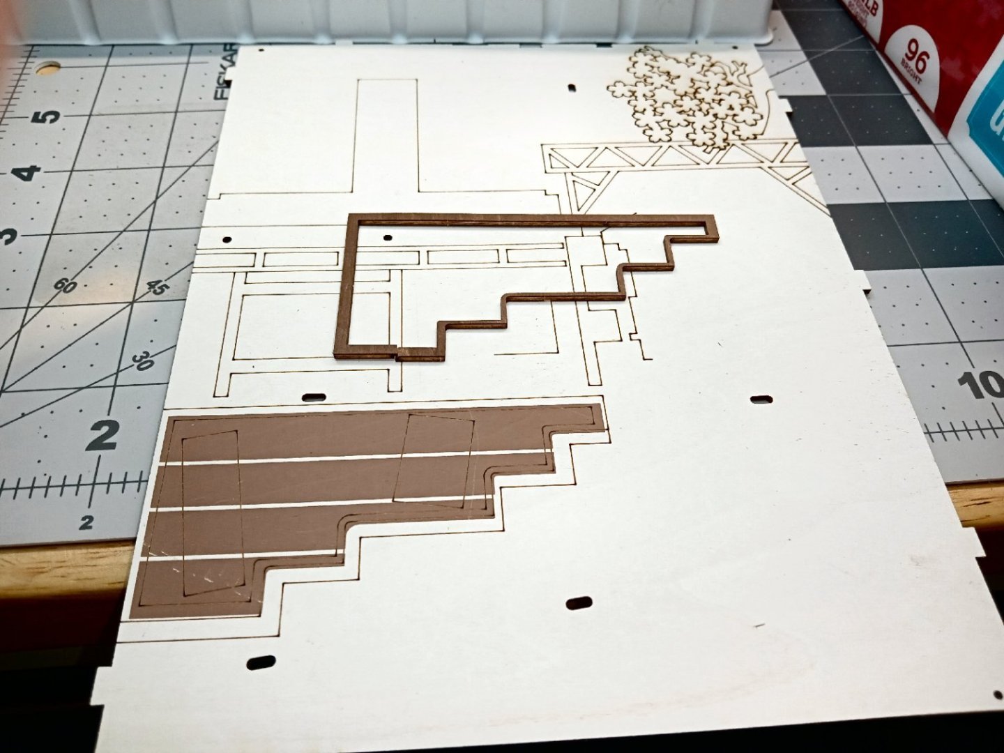
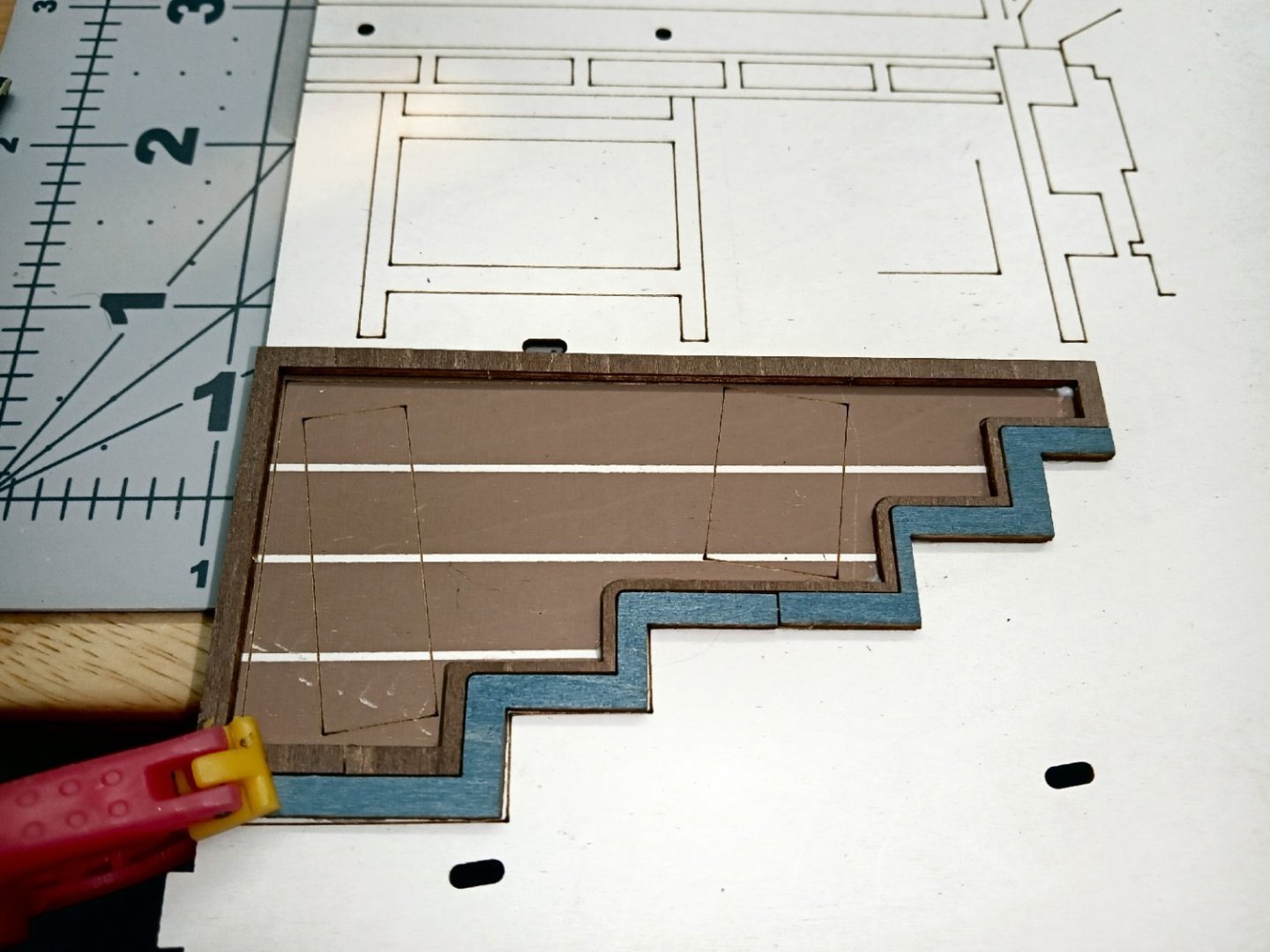
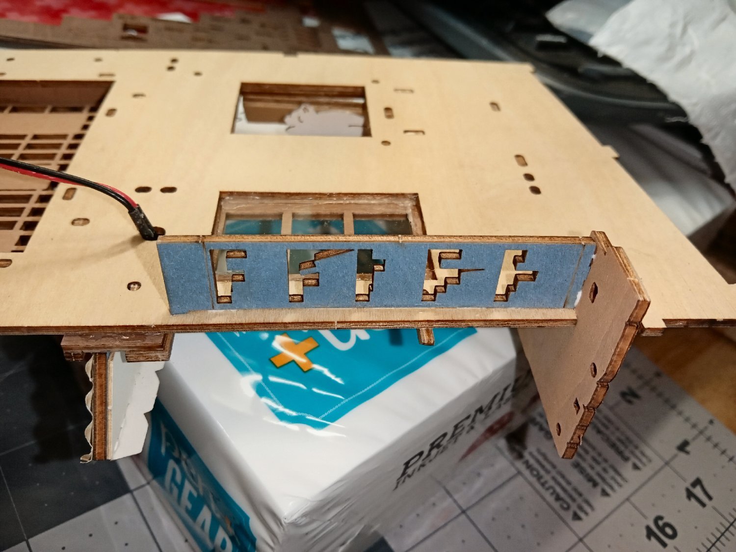
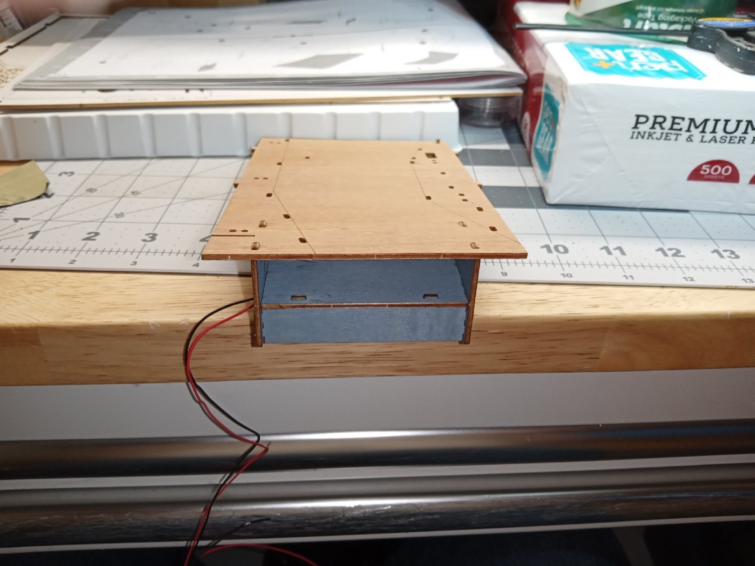
Before the front masonry piece is installed, the LED power switch circuit board has to be screwed on.
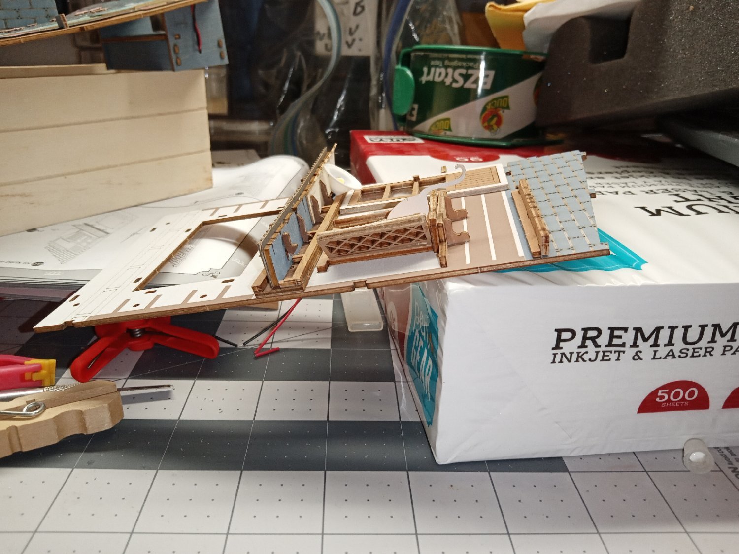
Here is the part installed. I had to use one of my regular sized clamps to hold the streambed edge of the part flush with the stream, until the glue dried. The front to back length was too long for my modeling clamps.
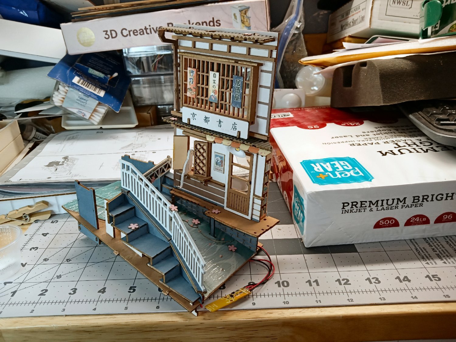
This shows the progress so far.
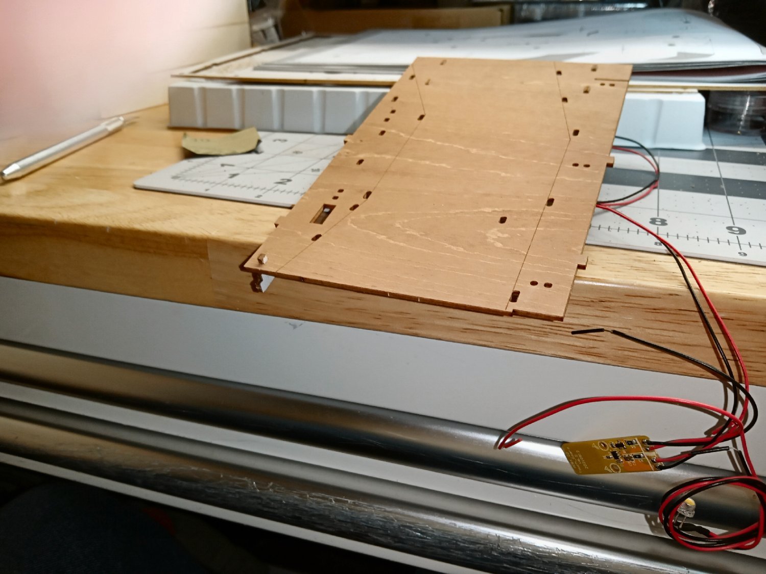
As I have had ant problems in the shop, I glued the plastic water piece down along the front and back, to make sure they don’t get under there if they show up in the future. I used the clothespins to spread the weight of the glue bottle, to hold the edge down while the glue dried. The weight of the clothespin on the far right was enough to hold down that section.
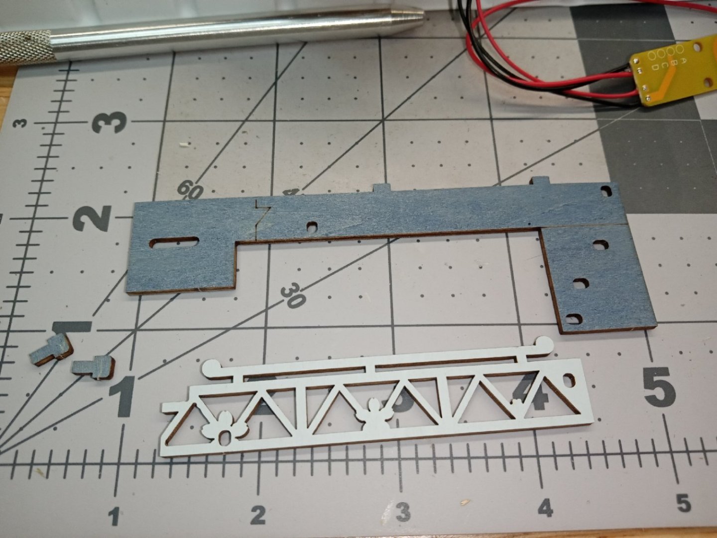
It turns out I was wrong in an earlier post; the model does have a second LED. It goes at the top of the model, in a dedicated holder.
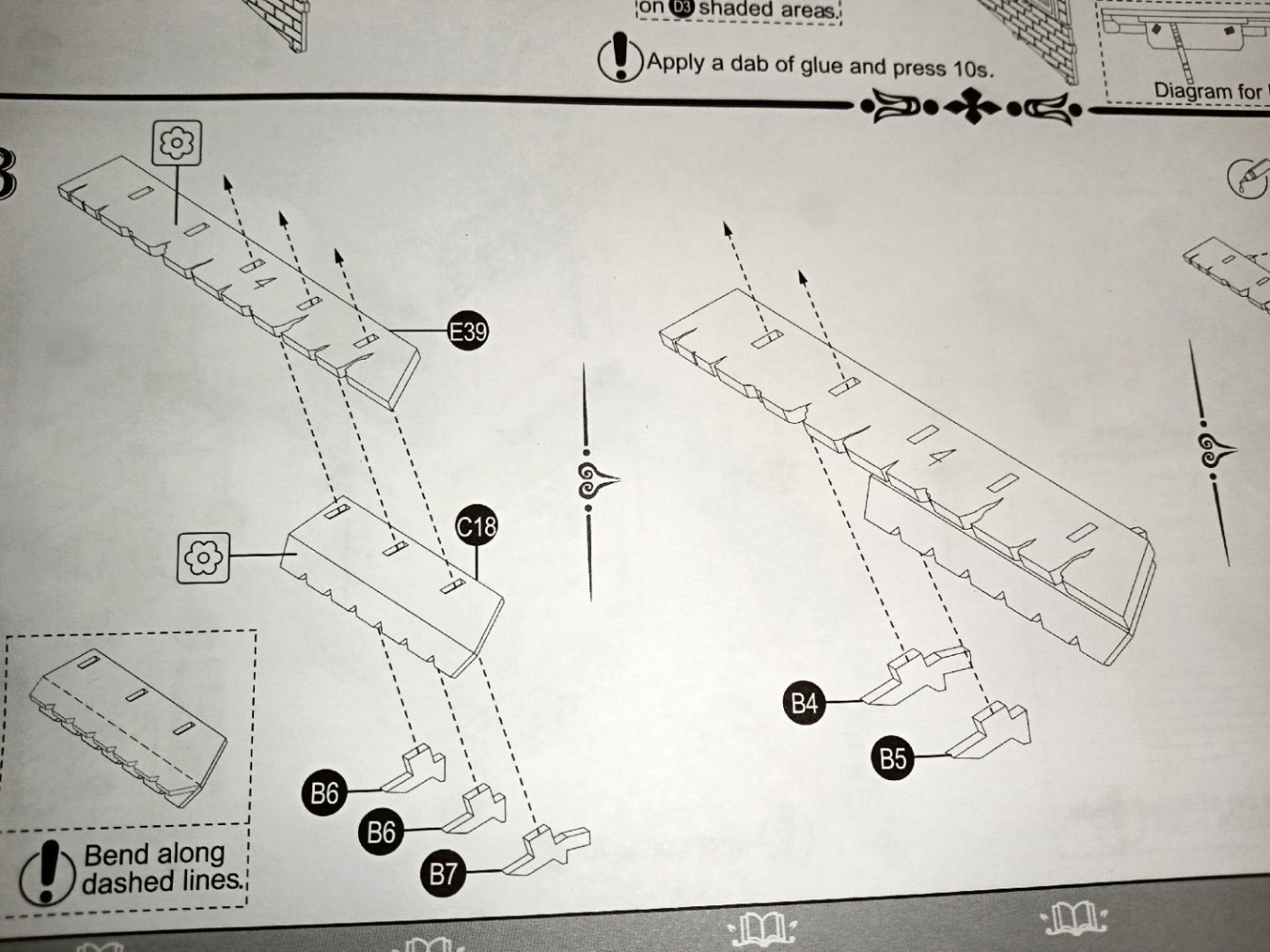
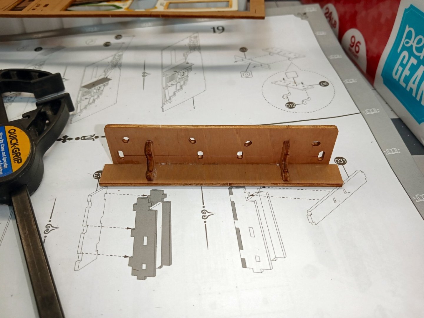
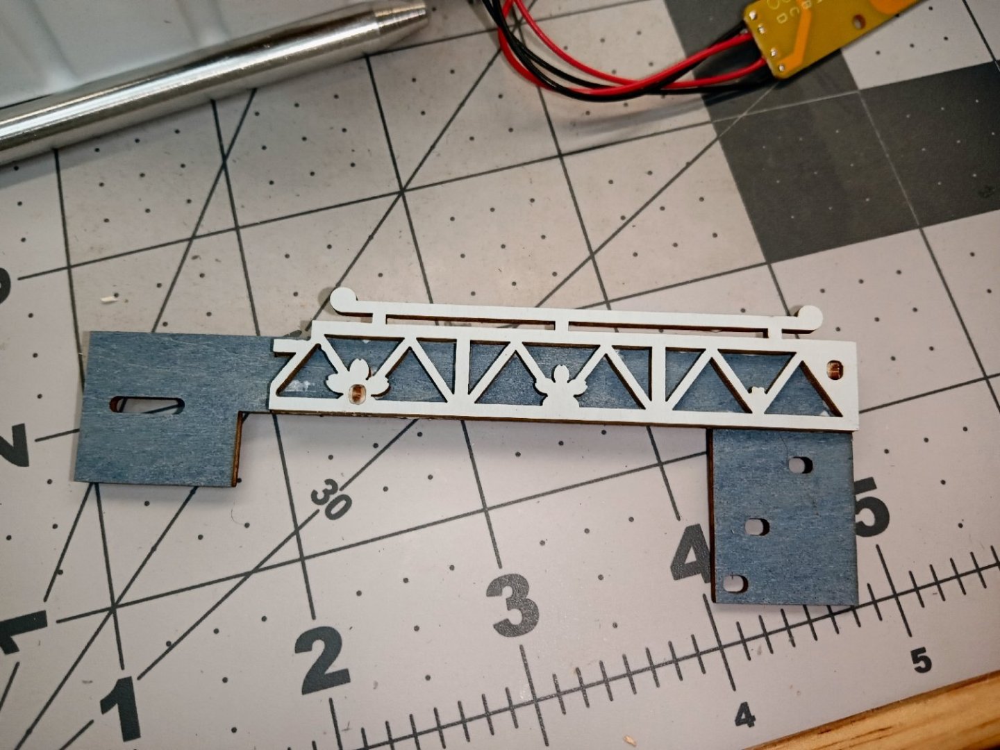
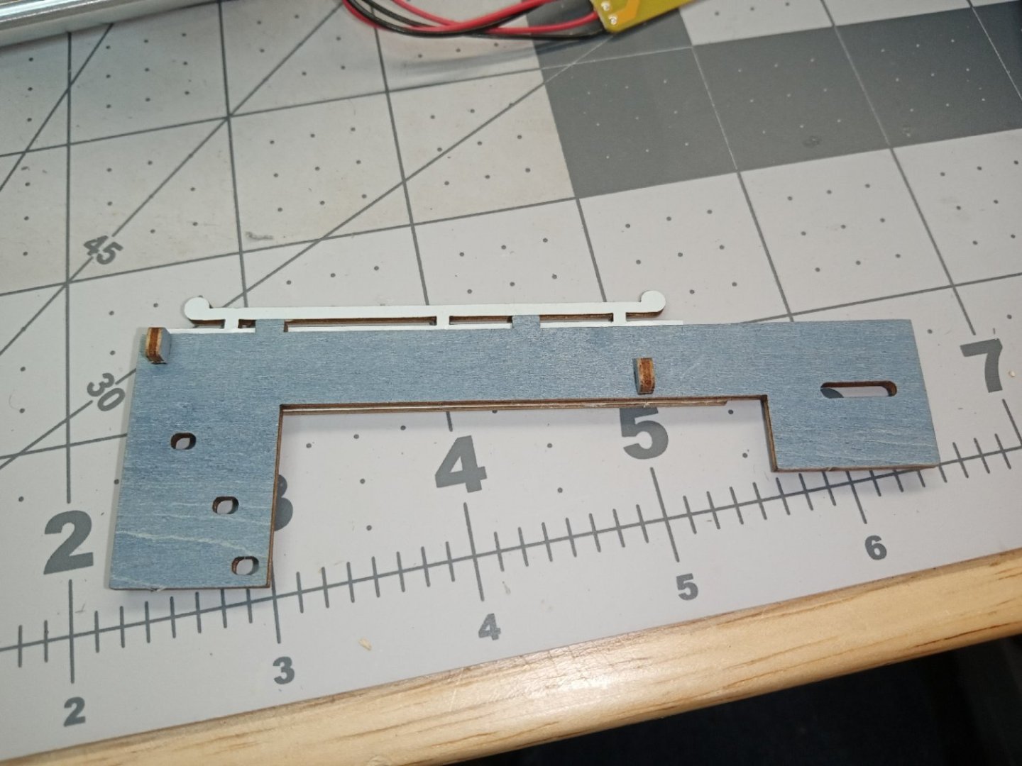
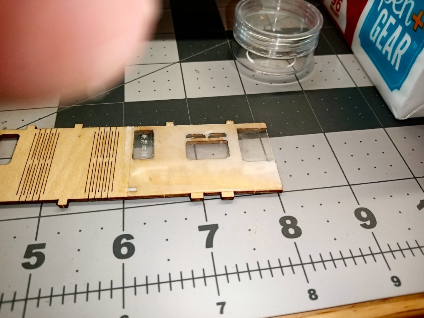
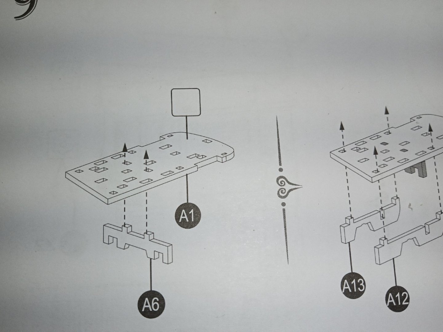
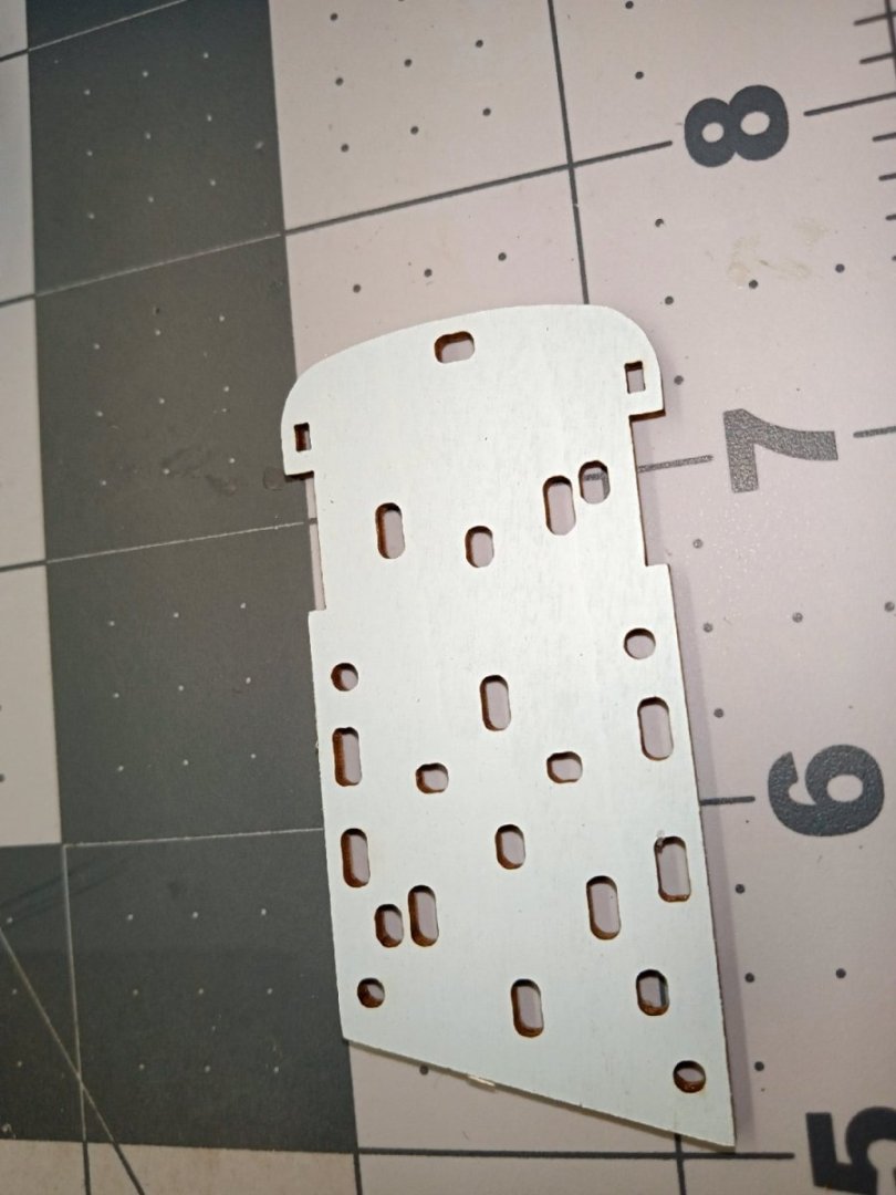
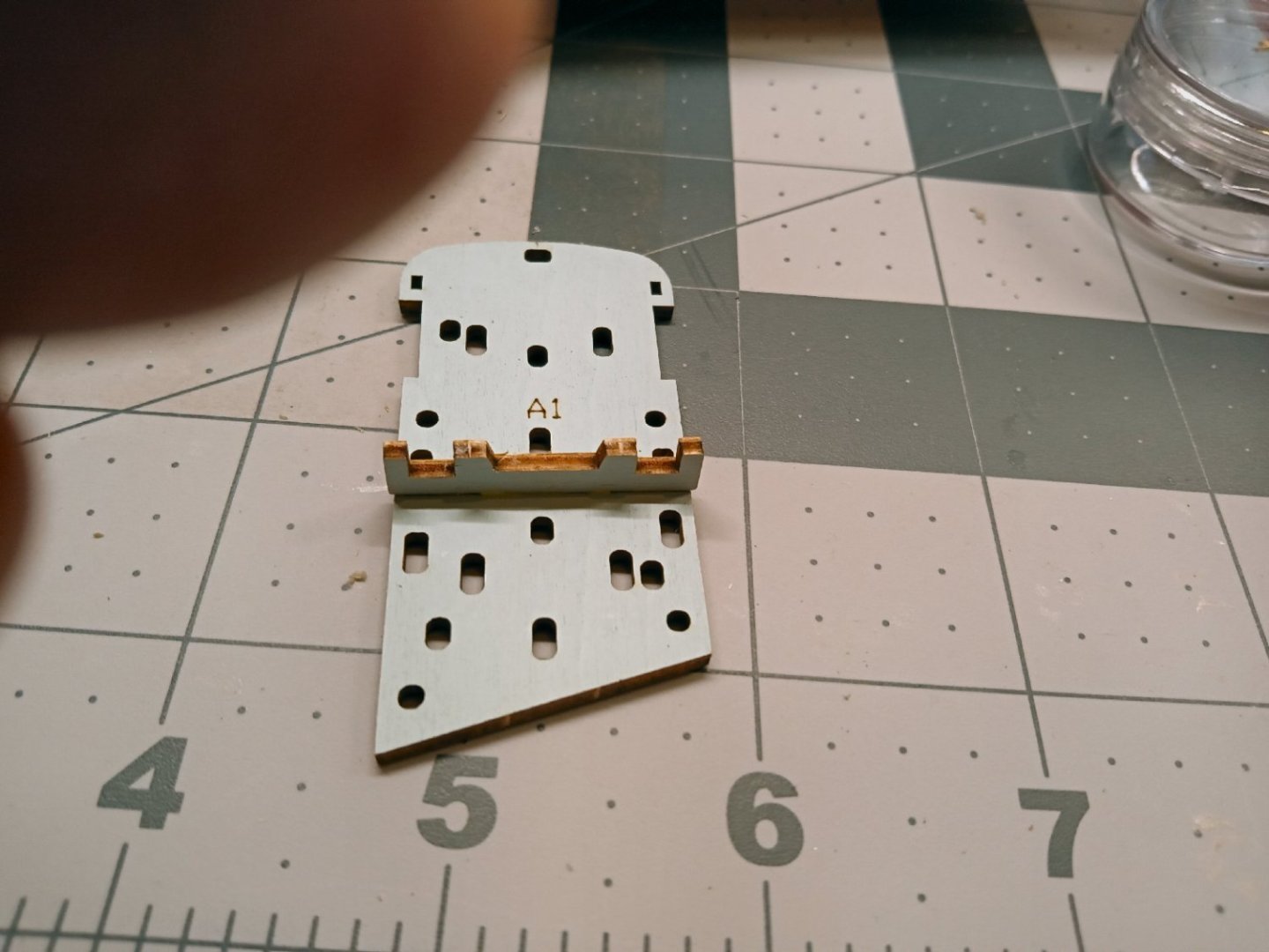
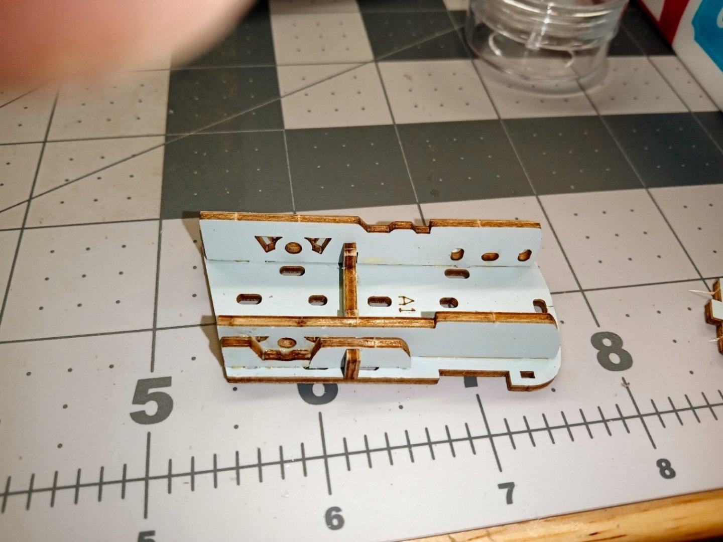
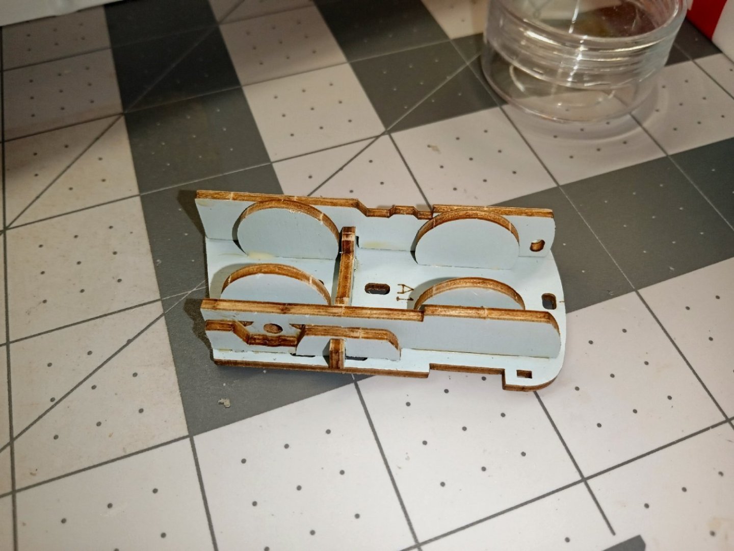
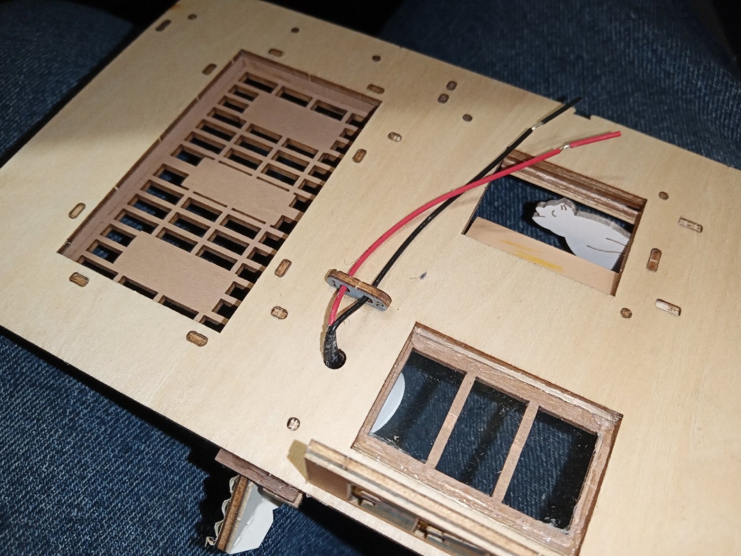
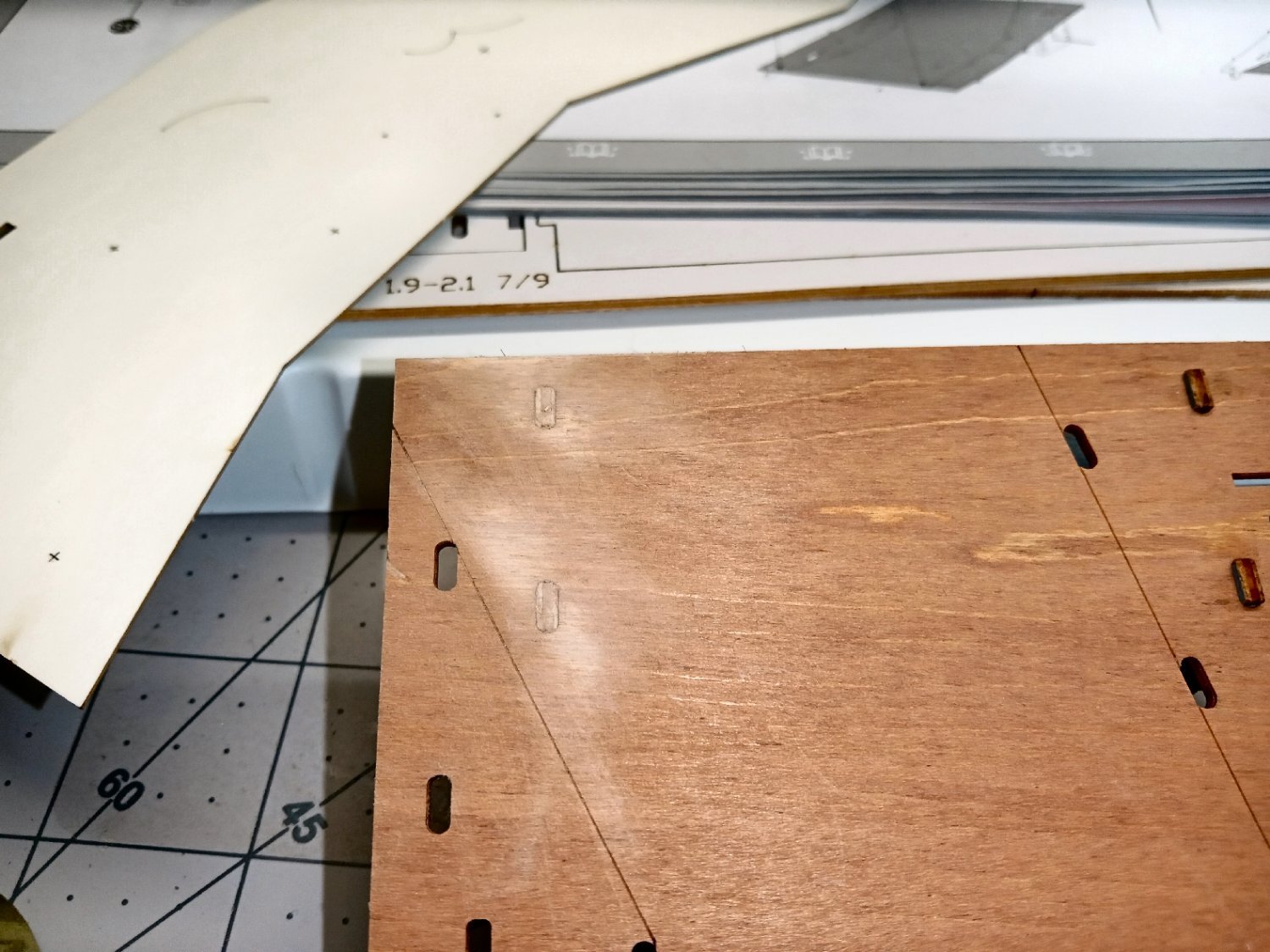
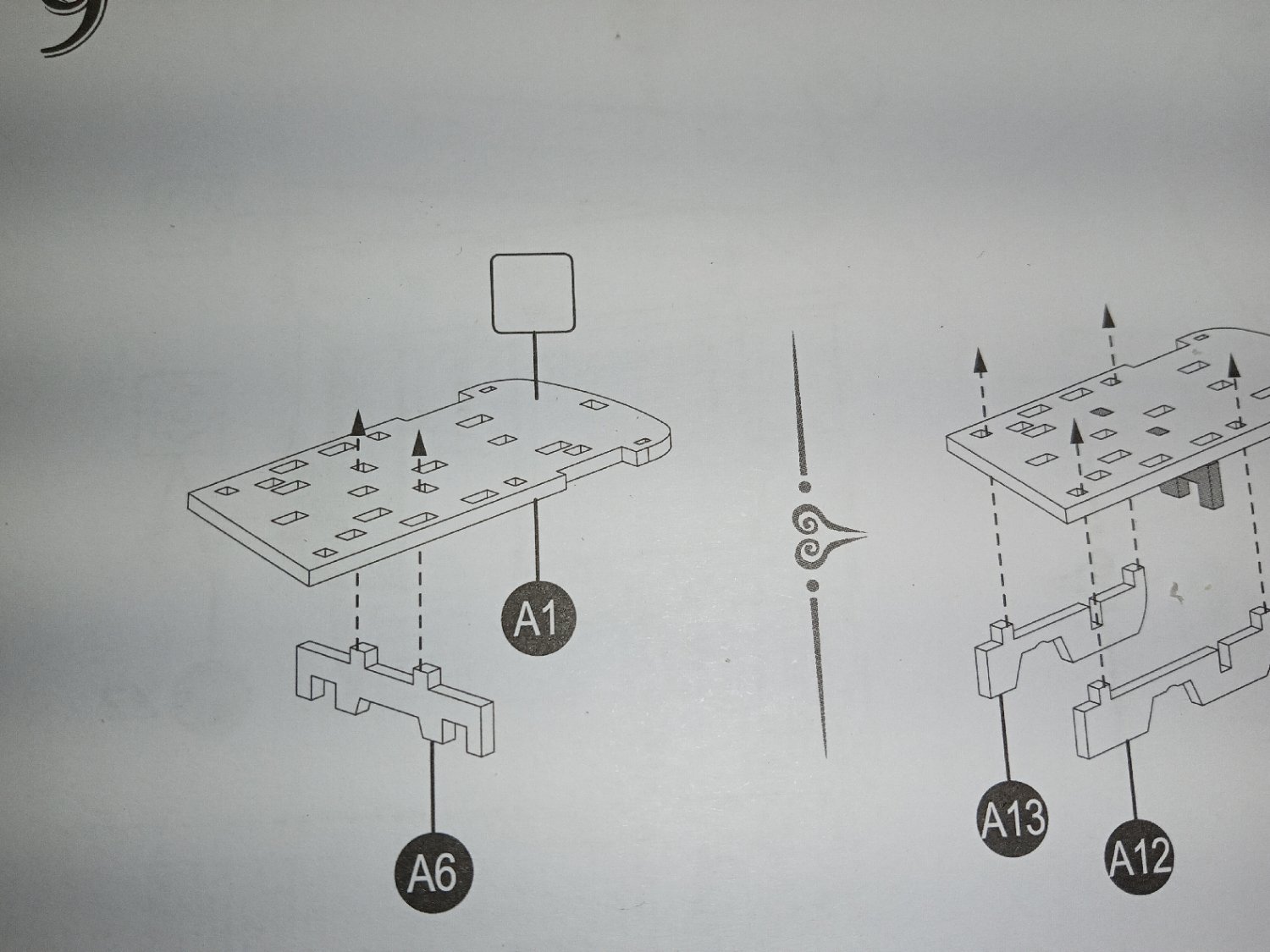
Construction starts with a base that spans between the left wall and the inner right-hand wall. The base has two wood staples that align the three center standoffs that the LED lamp globe attaches to. This shows the base with one of the staples installed.
The photo shows the base and three standoffs glued together. The top standoff is shown being installed with the colored side facing toward the base, but I decided to leave the colored face exposed. The part is symmetrical, side to side, so the parts still line up.
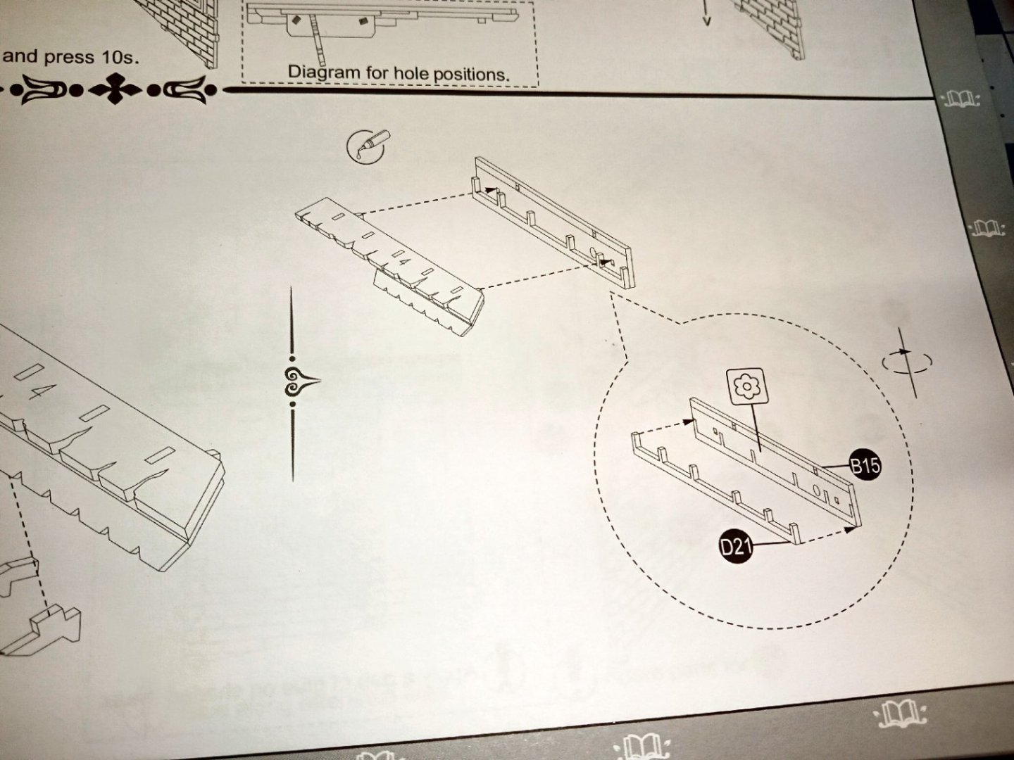
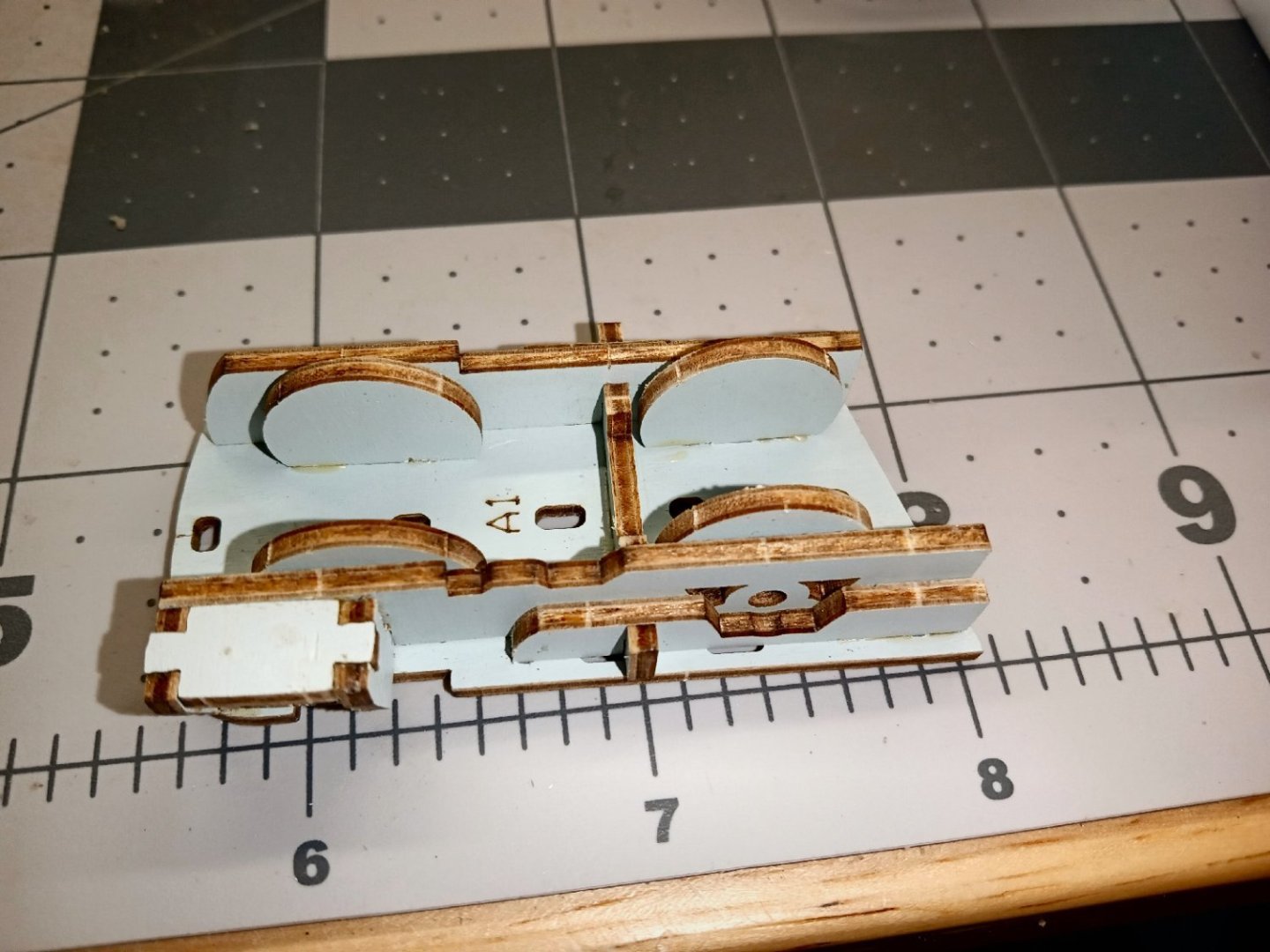
Next two more staples are installed to hold the wires that go to the LED.
The LED globe is designed as a press fit, but I added glue between the globe and standoff, on the inside, to make sure it stays in place.
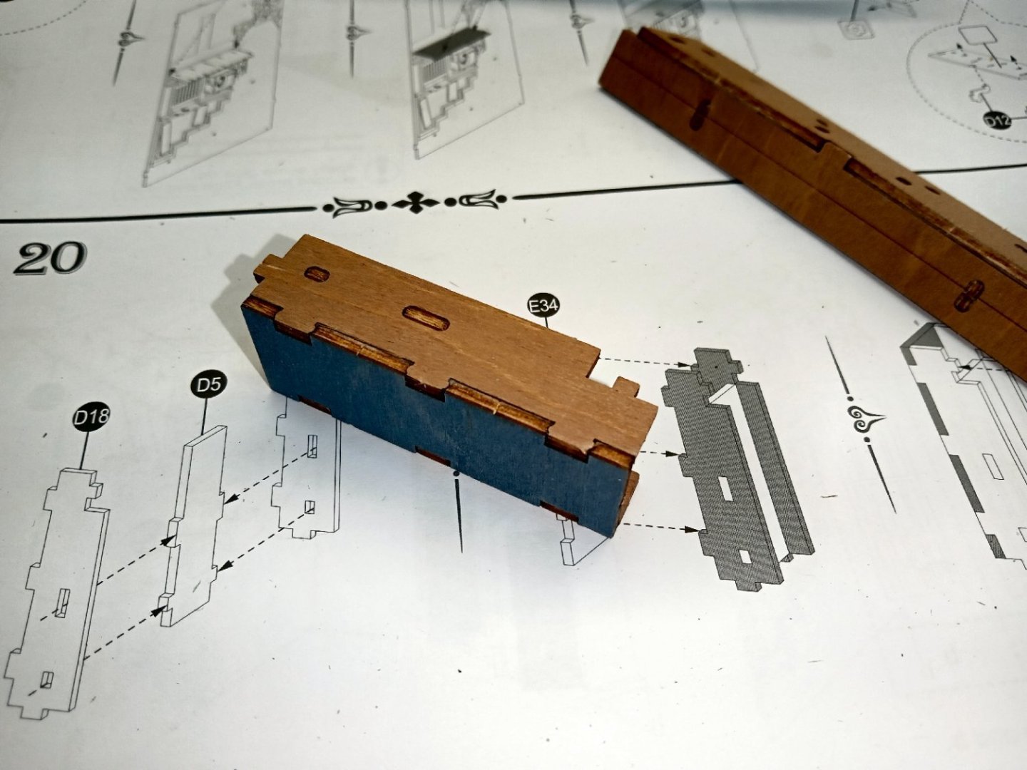
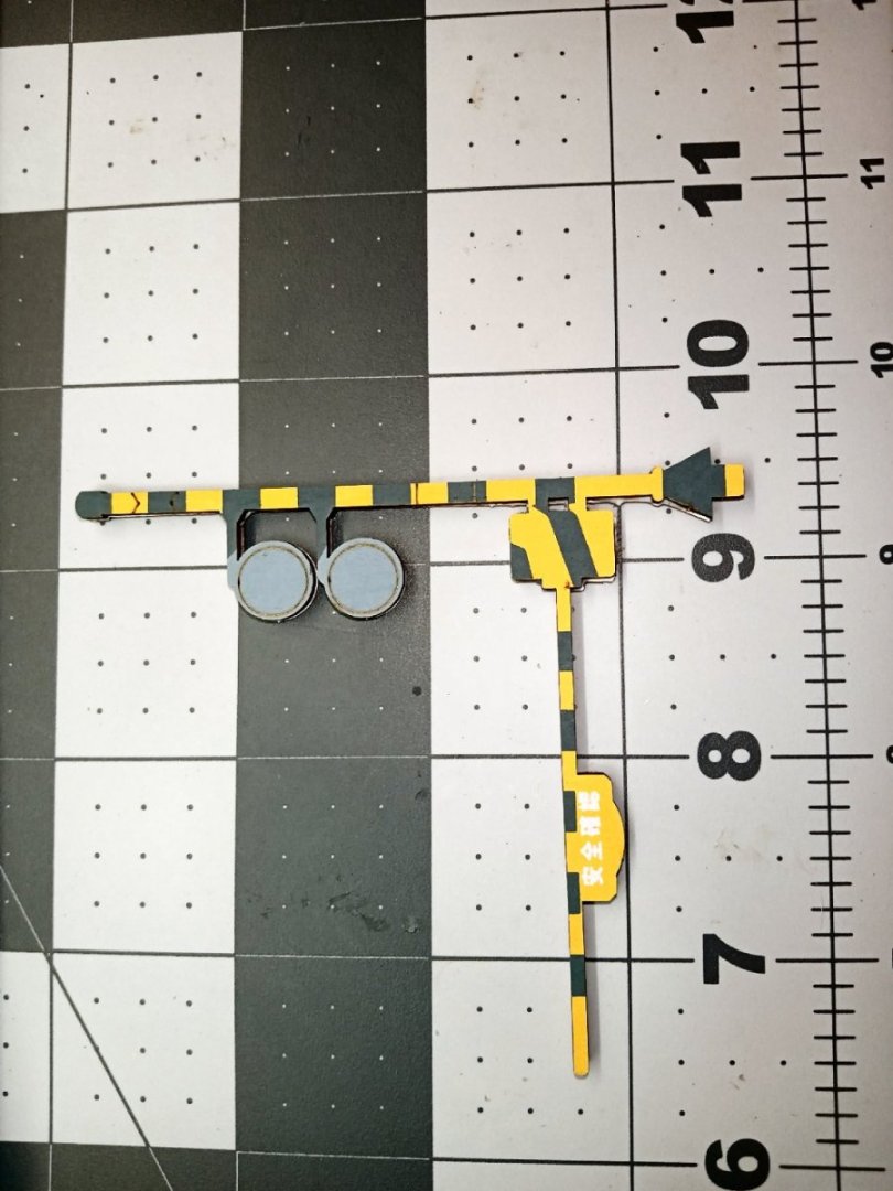
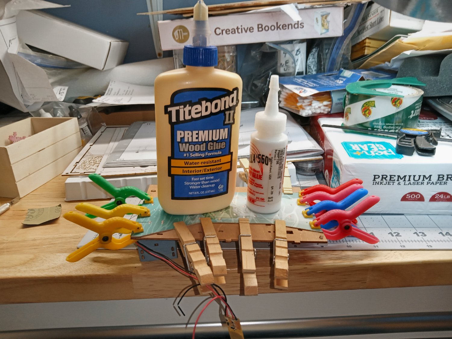
To hide the LED support, there is a faceplate installed
I had to clamp it in place while the glue set. I used the clothespin clamp for the section that had the slit for the wires. Hard clamping this across the slit risks breaking one of the arms off. I broke an Atlas lathe belt tensioner assembly a couple of decades ago, making that type of mistake. Luckily, I was dealing with a used machine tool dealer, back then, that sold me a whole newer, better designed, belt tensioner assembly for a reasonable price.
After the pieces set, I panted the colored areas and the staples white, to hide all the raw edges, just in case any of it is visible in the finished model.
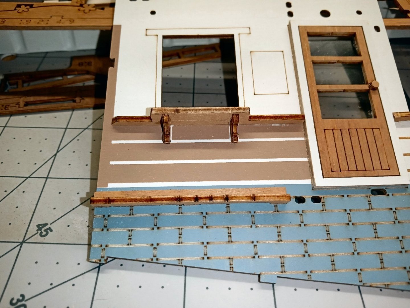
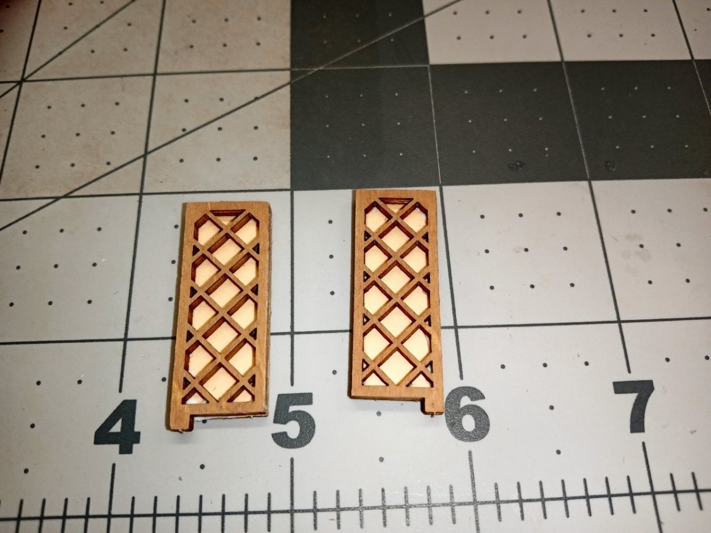
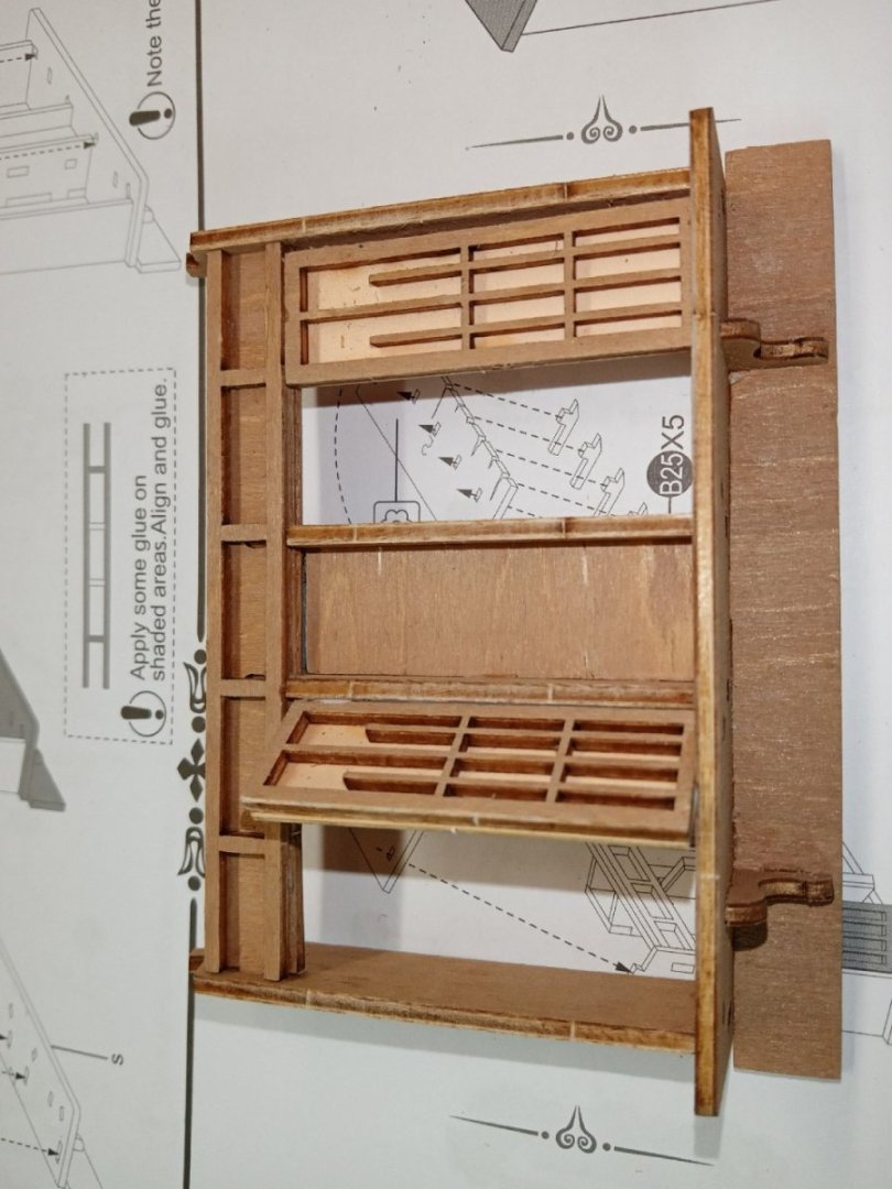
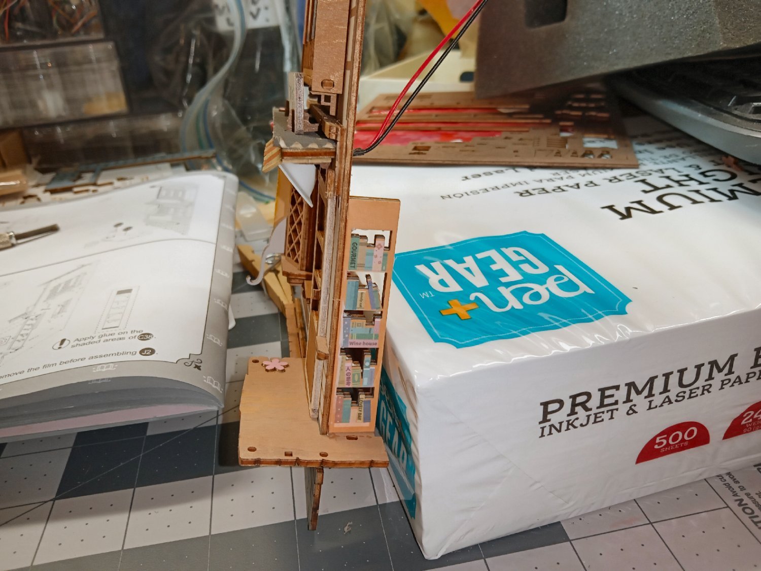
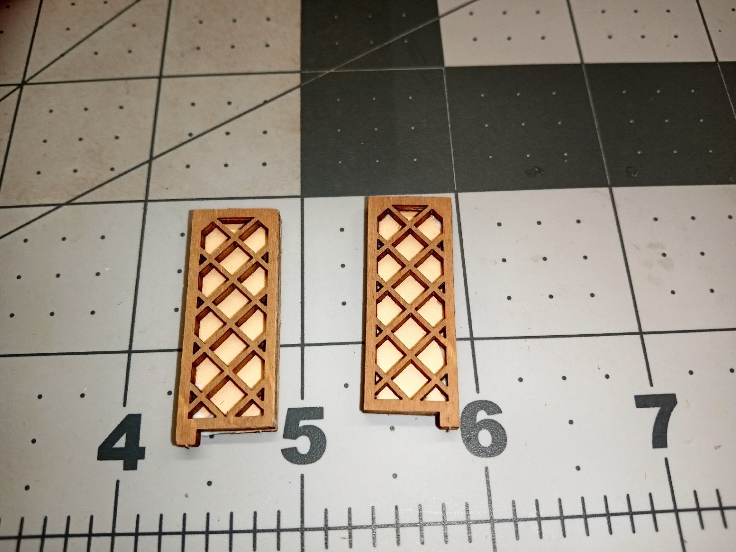
There are two support pieces for the LED assembly that need to be glued to the right-hand inner wall.
I had glued and clamped these in place, then found much further back in the instructions, that there was a trim piece that locked into this support! The glue had set already, and the clamps had distorted the support slightly up at the back. I had to break the glue joint and then install the trim piece, then reglue everything. In my defense that trim piece was rather hidden in the instructions, still I should have checked. The piece is the lattice work part on the right of the pictures.
I painted the raw edges of the upper front face piece white to match the color of the part. It took three coats to fully hide the edges, on this majorly visible area.