


thibaultron
-
Posts
2,644 -
Joined
-
Last visited
Content Type
Profiles
Forums
Gallery
Events
Posts posted by thibaultron
-
-
Part 4
For the rest of this thread, I will assume you are planning to print your model yourself, or need to generate a print file to give to someone else to print.
If you are just starting out 3D Resin printing, there is a lot for you to learn, and I can not cover it all here. This will be a quick review of the setup of the supports for a cannon, and creating the printer file. I suggest asking questions on this forum, and a deep dive into YouTube videos on the subject of your 3D printer.
Let’s discuss 3D resin printing a little more before we continue with the next steps in getting your file ready for printing. Earlier I discussed why the resin printer is better for small models and fine detail than the filament type printer. Now let’s talk about the differences in how they print a little more.
A filament printer prints by adding melted plastic in layers to build the model up from the base plate to the top of the model.. Assuming no supports are needed, this means that only the actual parts of the model need to be worried about. Empty spaces are just that empty.
A 3D resin printer is quite different. It has a build plate that lowers into a vat of resin. A, generally, UV screen below the vat, projects light in the shape of that layer of the model, through a clear sheet that is the bottom of the vat, and the resin the UV light hits hardens. The build plate then raises up to pull that layer free of the bottom of the vat. The clear sheet has a non-stick surface. The build plate then goes back down, slightly less, as it already has a layer on it. The next layer hardens, and the process continues until the print has completed.
Here is a picture from the manufactures site of the printer I use, an Anycubic Mono 4K printer.
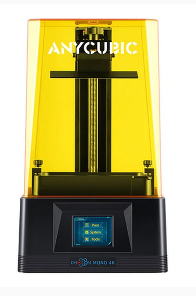
The vat is the black tank at the bottom of the yellow plastic encased area. The build plate is attached on the vertical arm near the top. The UV light source (a LCD type screen) is just below the vat.
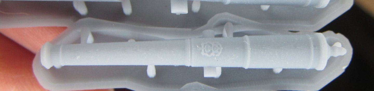
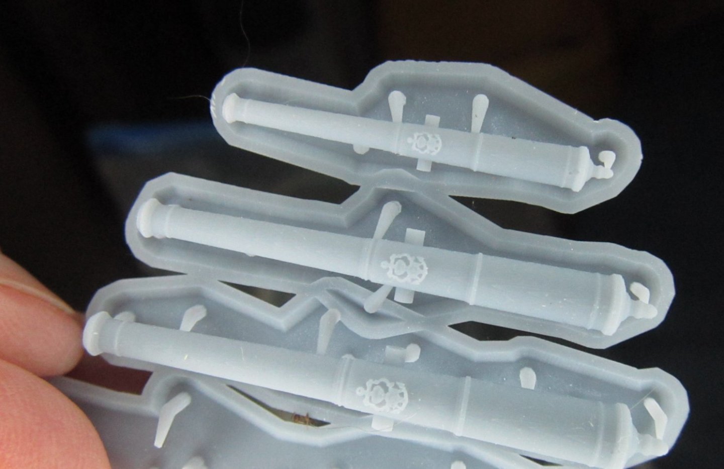
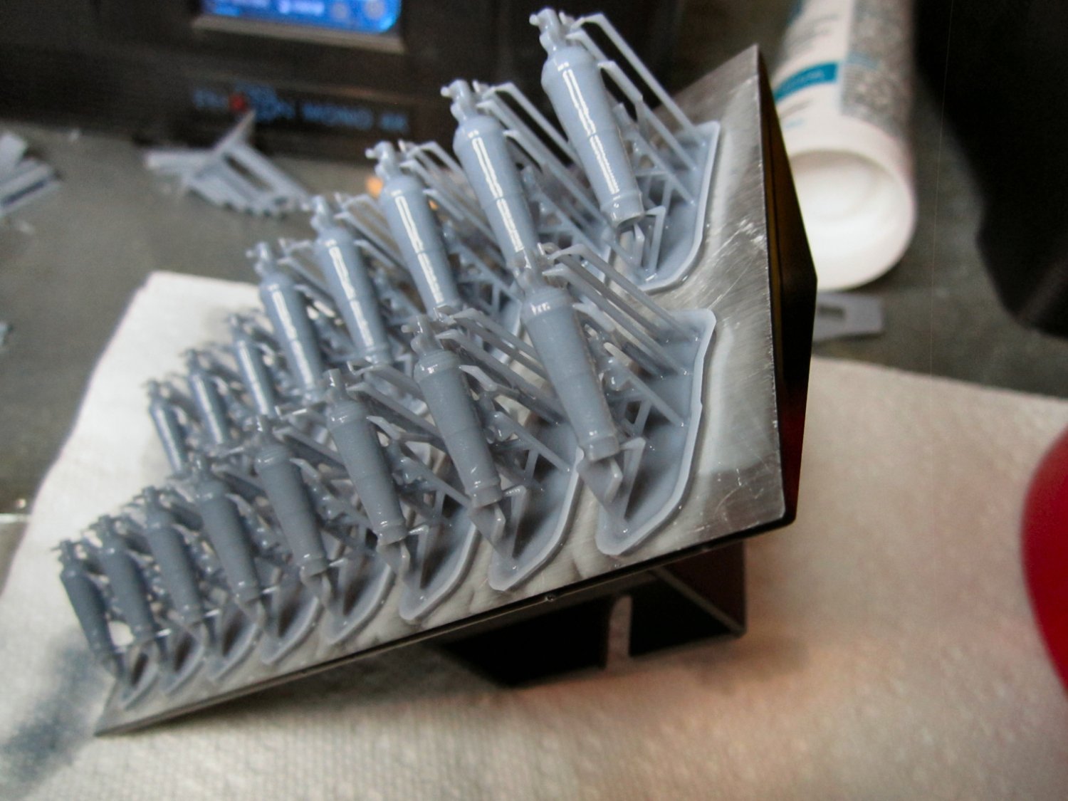
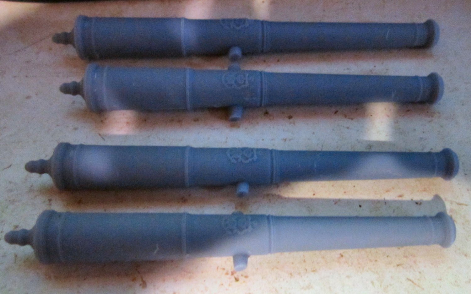
Here is a picture of a finished print I did. The build plate is upside down on the bench, and the print is attached to what is normally the bottom working surface. The cannons are shiny because they are still coated with wet resin. After cleaning and curing, they will typically have a matt finish.
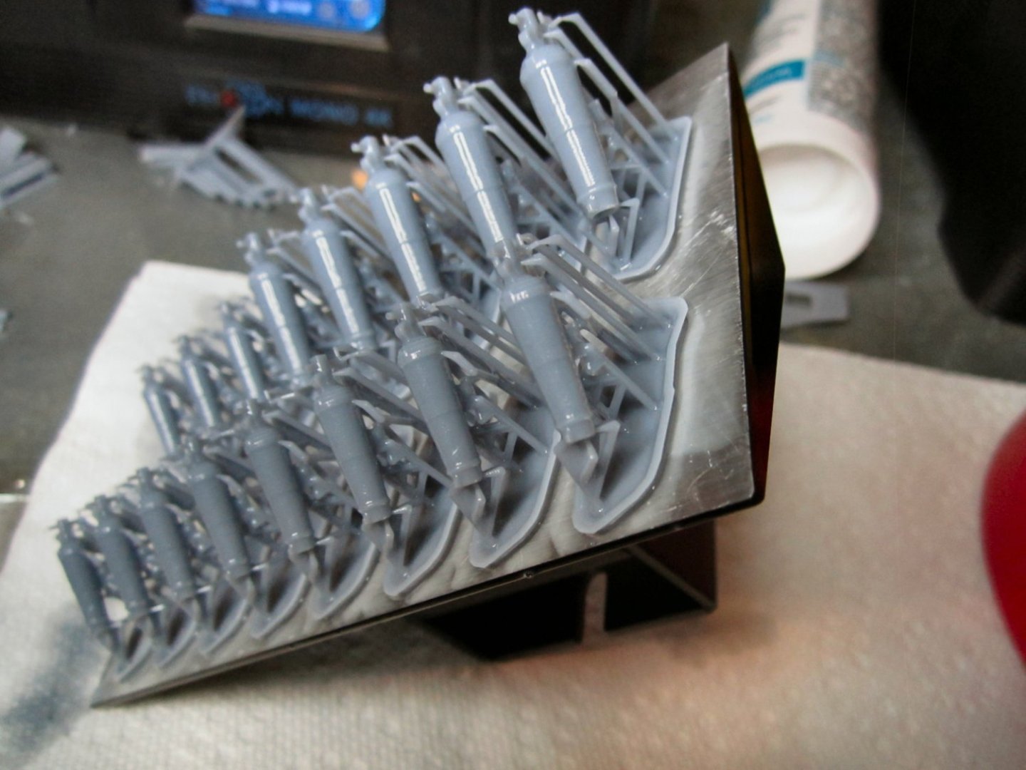
As the build plate goes up and down, the last layer hardened generally stays in the pool of resin. When the print is done the print and build plate are fully retracted, and excess resin is allowed to drip off the parts.
You will notice that for the print above, the muzzle openings face toward the build plate. I did this because the breach end of the cannon includes the elevating mechanism, which has four thin rods that make up the handles that turn the screw that elevates the gun. These are very thin in the model, and I wanted them free and clear to carefully break away the thin supports I used for them. If the cannon had been turned with the muzzles pointing away from the build plate, I was afraid that in removing the other supports, I would break the thin handles. This worked fine, but presents a problem. Remember the print would be on the underside of the build plate, when printing. This means that as the barrels print the resin can drip out of them, until the bottom of the bore is reached! This will trap some of the resin in the barrel, while the back end of the gun is printing, and stays there while the resin is dripping off at the end of the print.
The resin is quite thick, somewhere between maple syrup and heavy cream. So once the plate is turned over, like in the photo above, some of the resin will still stubbornly cling to the inside of the barrel for quite a while. I ended up running the end of a small dowel inside the barrel to help clean out most of the remaining resin.
The better way to print a cannon like this is with the muzzle pointing away from the build plate, toward the vat. This allows much better drainage while the cannon is printing. Once again there were compelling reasons that I printed these cannons wrong-way-around.
Next you have to consider the general orientation of the model. While it may seem intuitive that you should print any model flat to the build plate, especially something with a flat bottom, this is not the case. This would conceivably reduce the number of needed supports, and save resin. But this is not the case.
The first few layers have to be slightly over exposed to firmly attach them to the build plate, so the model stays there during the rest of the print. This causes these first layers to be a little wider than the desired outlines, as some light leaks into the edges with the longer exposure. The base of the model thus elephant foots, as the terminology goes. So a cube, let’s say, would have a slightly larger rim on the bottom.
Next, remember that the model has to pull off the non-stick sheet, after each layer is exposed. This is not a zero force procedure! The larger the exposed area of resin in a layer, the more force is required! If a large enough force is needed, it may pull the whole thing off the build plate instead, ruining the whole print, or it may just pull the model away from that new layer, causing faults in the final print. Sometimes following layers may attach to this layer and pull it free, but the model will have a discontinuity in that area.
To get the best detail with the fewest layer lines, generally tilting the model at 45 degrees, and printing at a layer height setting equal to the size of the pixels on the UV screen, is best. For my printer, the pixel size is 35um (.035mm, or 0.00138 inches), so the layer height for these prints was set to the same 35um. Generally, you can find the pixel size in the printer details on the manufacturer's web site, or in the printer manual.
Why do we need supports? First if your model prints at an angle, if you just have a single support at the base, the bending stress as the model moves along and you are printing areas future away will put a bending stress on the support, and either cause it to fail, or distort the model (i.e. The barrel would come out bent).
Next we will visit the idea of “Islands”. Islands are parts of your print that have no attachment to the model or build plate when they are first printed. As they have no attachment to either, they simply stay attached to the film when the rest of the model pulls away, and just keep get wider and wider, as the print progresses, until some part of the main body of the model contacts them. This leads to a failure of the model, as it has features missing. Let’s take the example of the horse shown below as a simple example. It is shown upside down as it would be as it is printing, with the upper areas printing first.
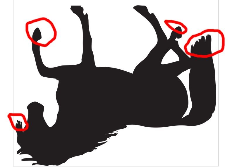
The circled areas are some of the spots that would be islands if no supports were used. These areas have no attachment to anything other than the vat film when the layer that they start on is exposed.
You also need to support thin areas where the force of pulling the layer off the film might cause it to bend into a curve. Rather than staying straight. This is especially true if it is the first few layers of a large thin or flat section.
Even the cannon we are trying to print can cause this bending problem if the barrel is parallel to the sheet. The first few layers of the barrel will be long and thin, if parallel to the screen.
So, long story short, it is best to angle almost all your prints.
Another consideration is the orientation of the model. You always want to position the side or edge that will be the least viewed toward the build plate. This is the area most of the supports will contact the model, so any divots that come from removing the supports will be on the least visible areas. For a cannon this would place the bottom of the barrel closest to the plate, for a figurine that is angled, position it so the back of the figurine has the supports, or whatever side will not be seen as well for your diorama. The divots can be filled, but still the less the filled areas that show the better.
If you model is too long to fit in your printer at 45 degrees, you will need to angle it so it does. This means for the best print, you may have to change the layer height, so as to reduce the effects of the appearance of the layer edges. I gave an explanation of this in the “3D Printing Process” thread. Page 10 about ¼ of the way down, along with a spreadsheet to help you figure the correct layer height for whatever angle you need to place your model at. The whole thread is good reading if you are just starting out.
https://modelshipworld.com/topic/29447-3d-printing-process/page/10/
https://www.youtube.com/watch?v=Qs2Rb0ExnIM&t=3s
Sorry, the above is not so “Quick” a write up as I was thinking of.
Part 5
Now we will look at a basic run through of importing, positioning, supporting, and exporting to a print file.
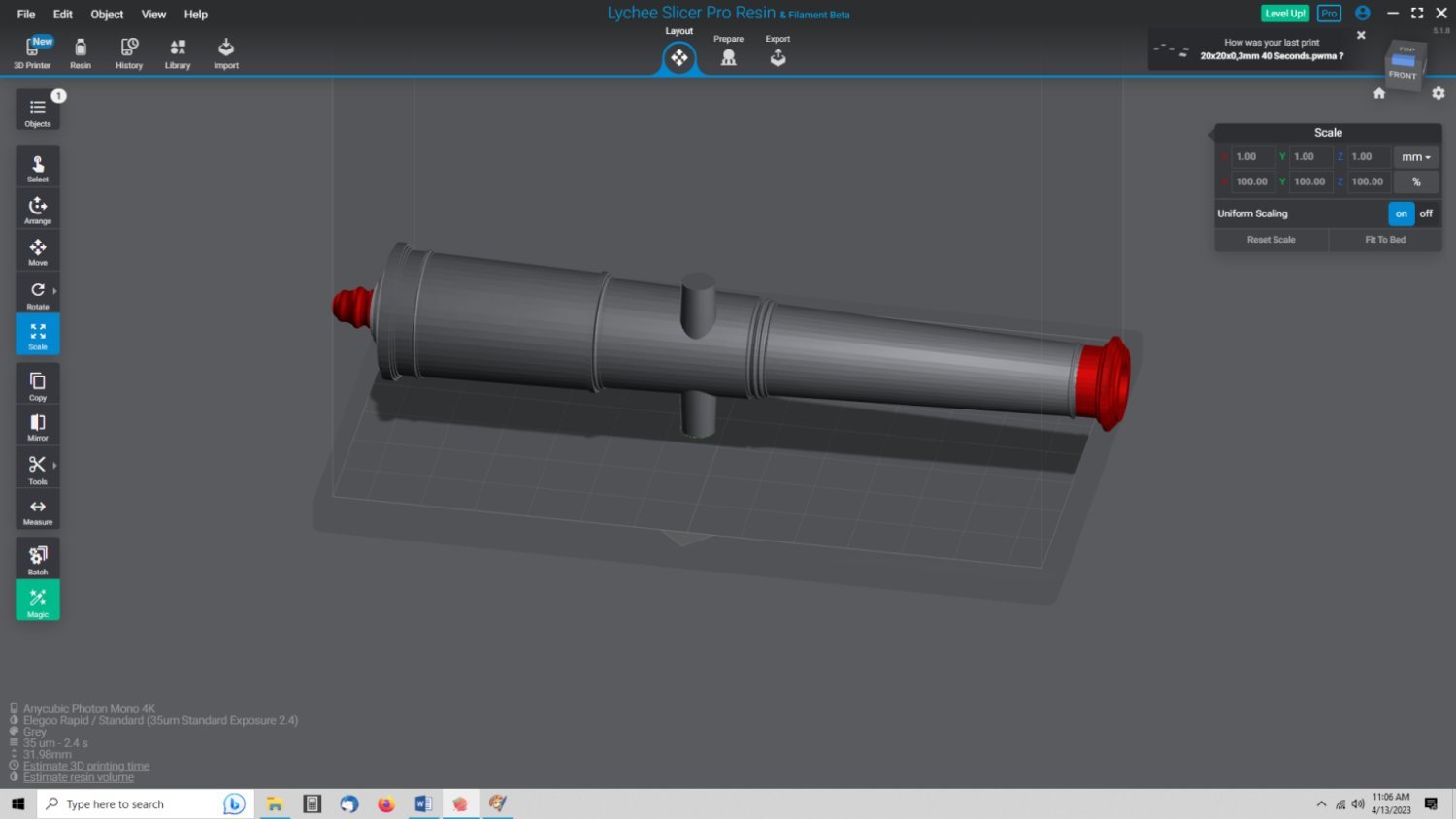
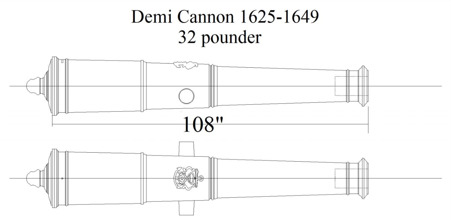
I showed how to import the model in the previous posting, so I will start with positioning the model before we start adding supports. This time I will use a bigger cannon model to make it easier to see. This model will be a 1/24th scale 32 pounder version of the same “Pattern”/model 6 Pounder cannon, I used last time.
Here I’ve just imported the cannon STL. Notice that the model has the trunnions vertical rather than horizontal, as in the drawing. This is not a fault with Lychee, It has to do with a various view options in the CAD program that I prefer to use while developing 3D drawings.
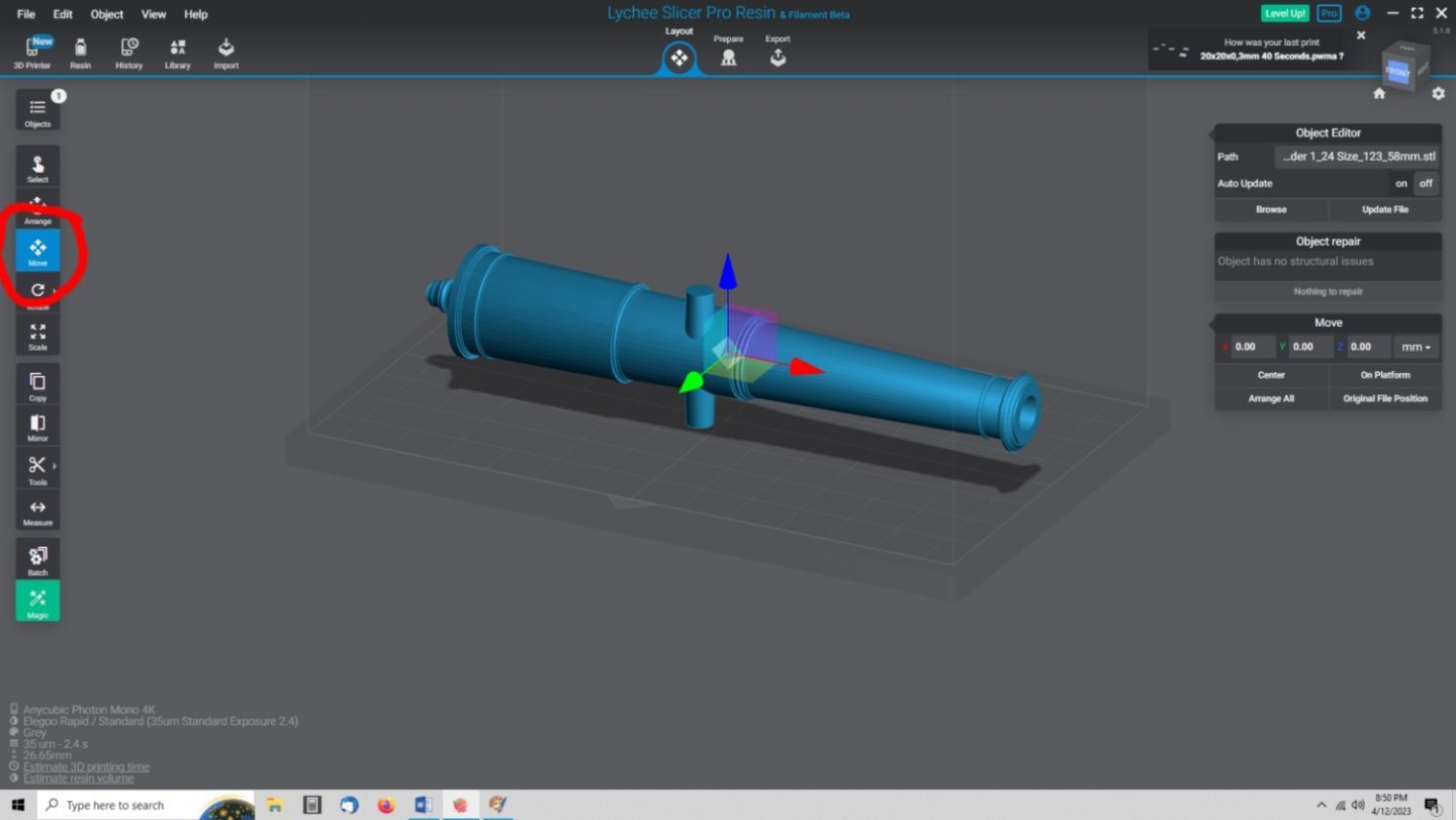
The bottom surface represents the build pate surface of the printer. In Lychee you select your printer manufacture and type during setup. The build plate and shadowed enclosing box on the screen, represents the actual Printable Volume dimensions for your printer. If your model is too large, the areas of the model that poke outside the printable volume will be shown as darker areas or red areas, depending on what operation you are doing, or if the model is selected or not.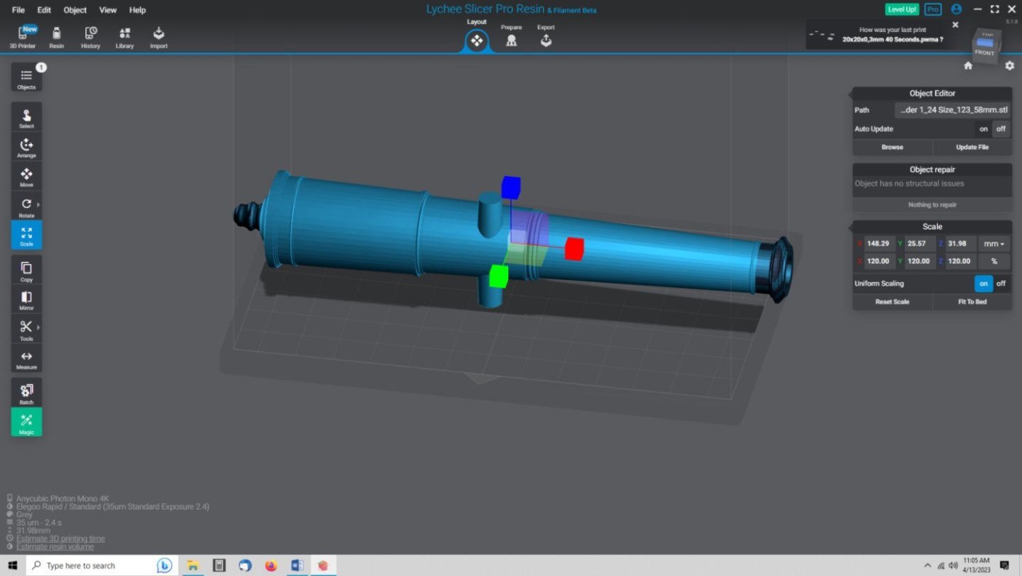

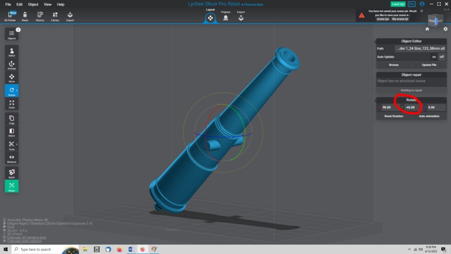
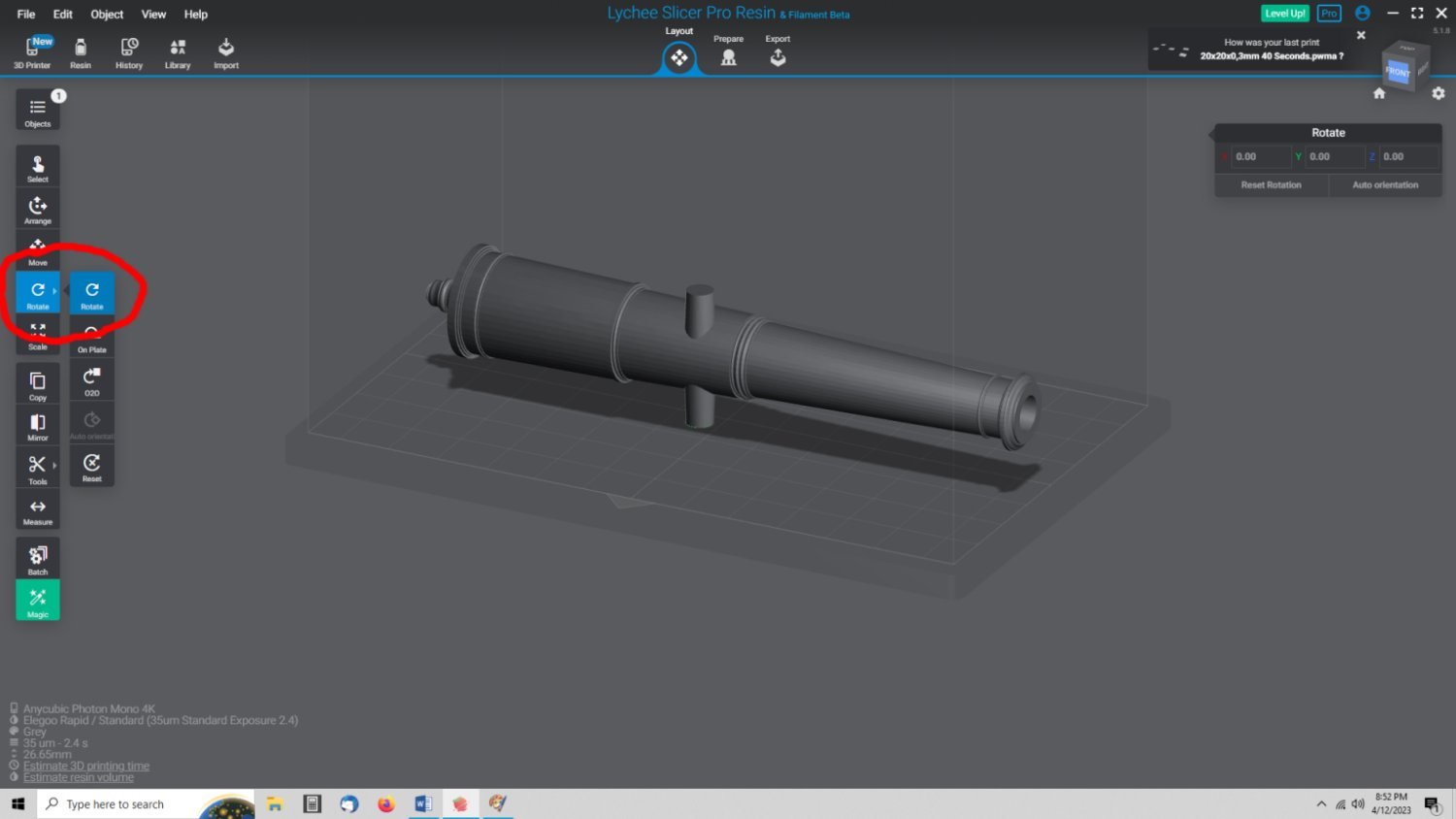
The first steps I want to do in preparing this model are to rotate it so the bottom of the cannon faces the work surface in the program.
When you first import the file, Lychee defaults to “Move” being the selected operation. We need to get the cannon oriented correctly first, I selected the “Rotate” function.

Then I selected the model and these windows opened in the right hand of the screen.
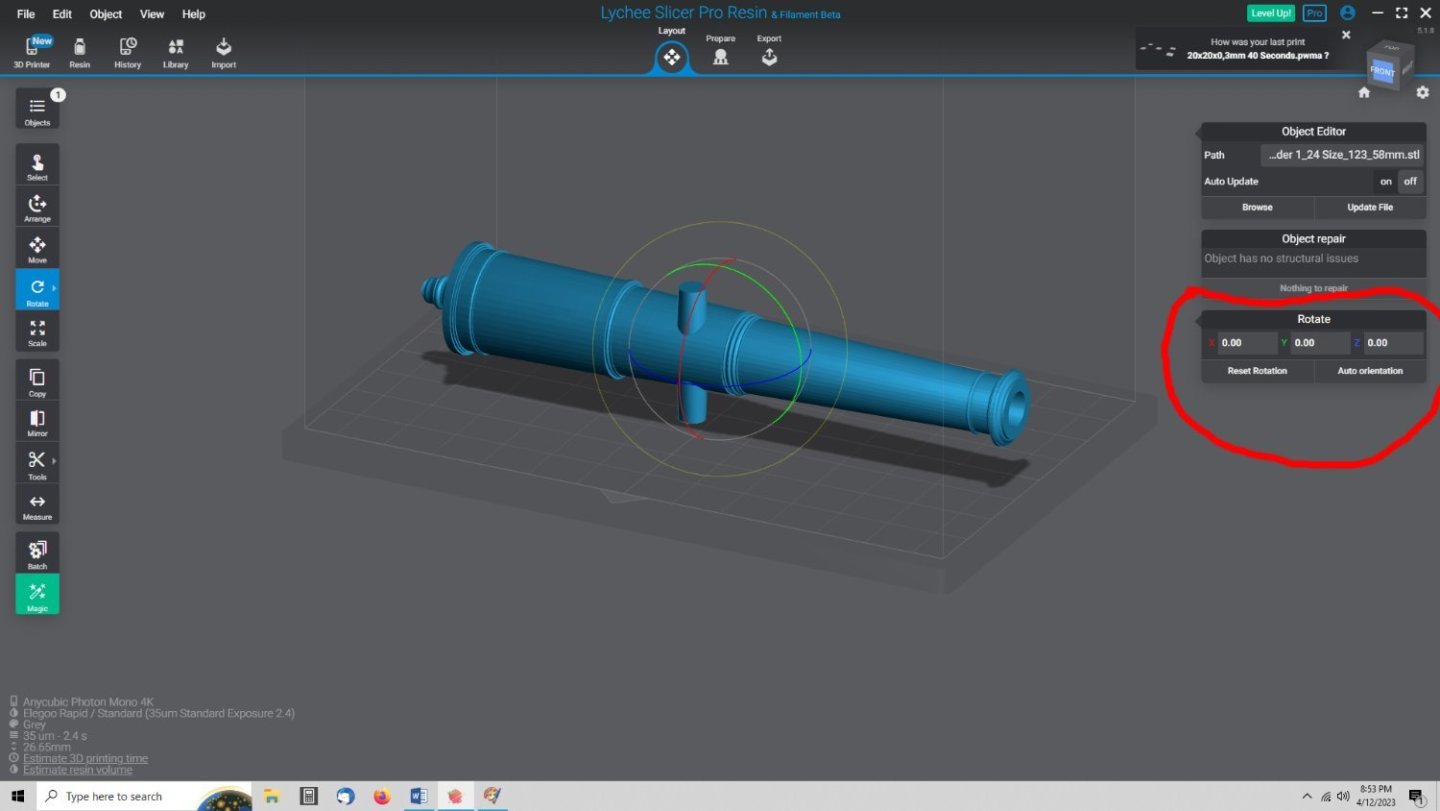
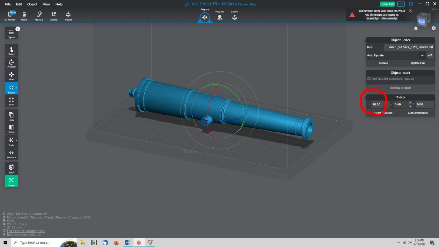
We need to do two operations, rotate the model 90 degrees on the X axis so that the bottom of the cannon faces the build plate, and -45 degrees in the Y axis, so the muzzle faces “Down” while printing, as discussed earlier. The program displays three differently colored circles during the rotation process, these show you which way that the model will rotate for each axis. Red for X, Green for Y, and Blue for Z. After entering a value, it will not be applied, until you click outside of the data entry box.
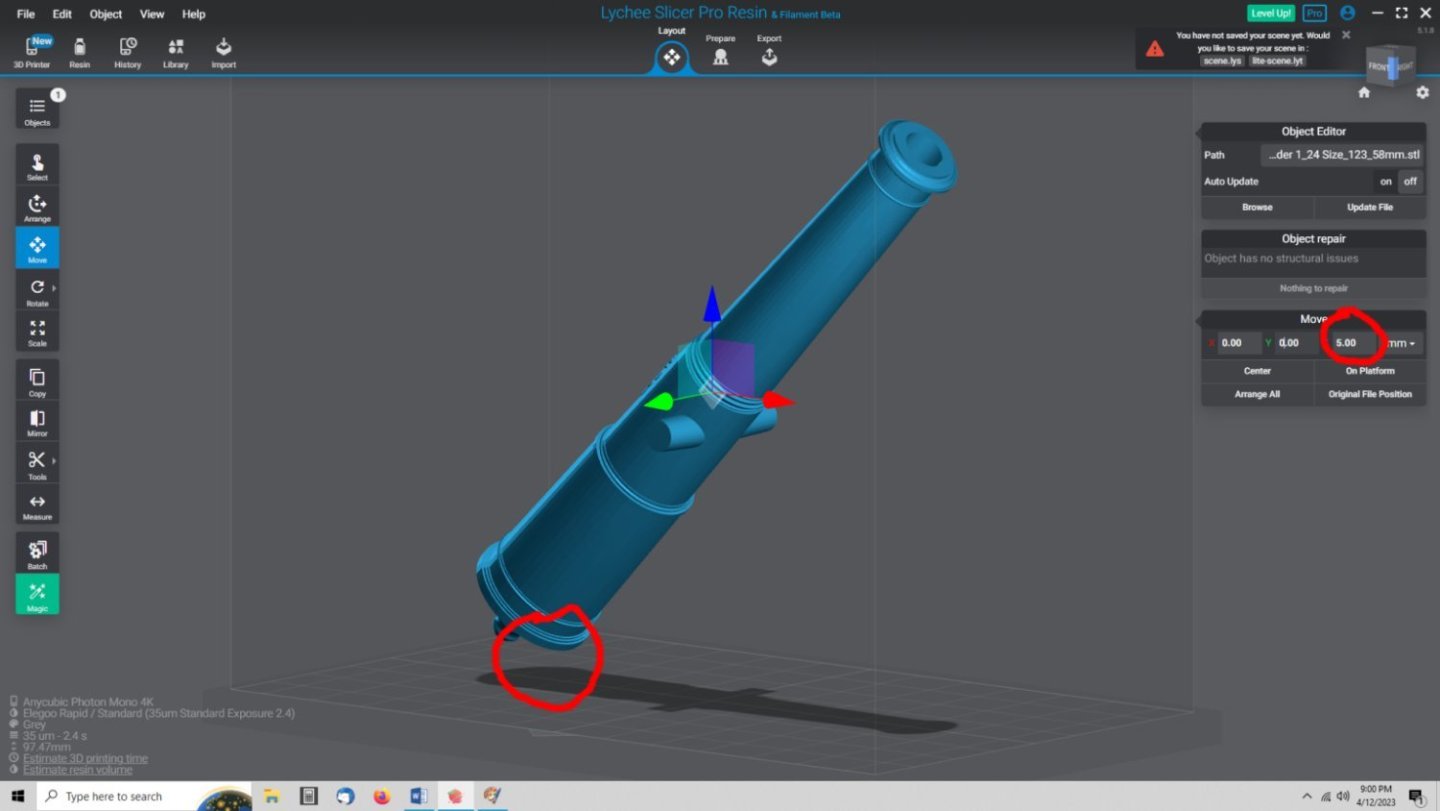
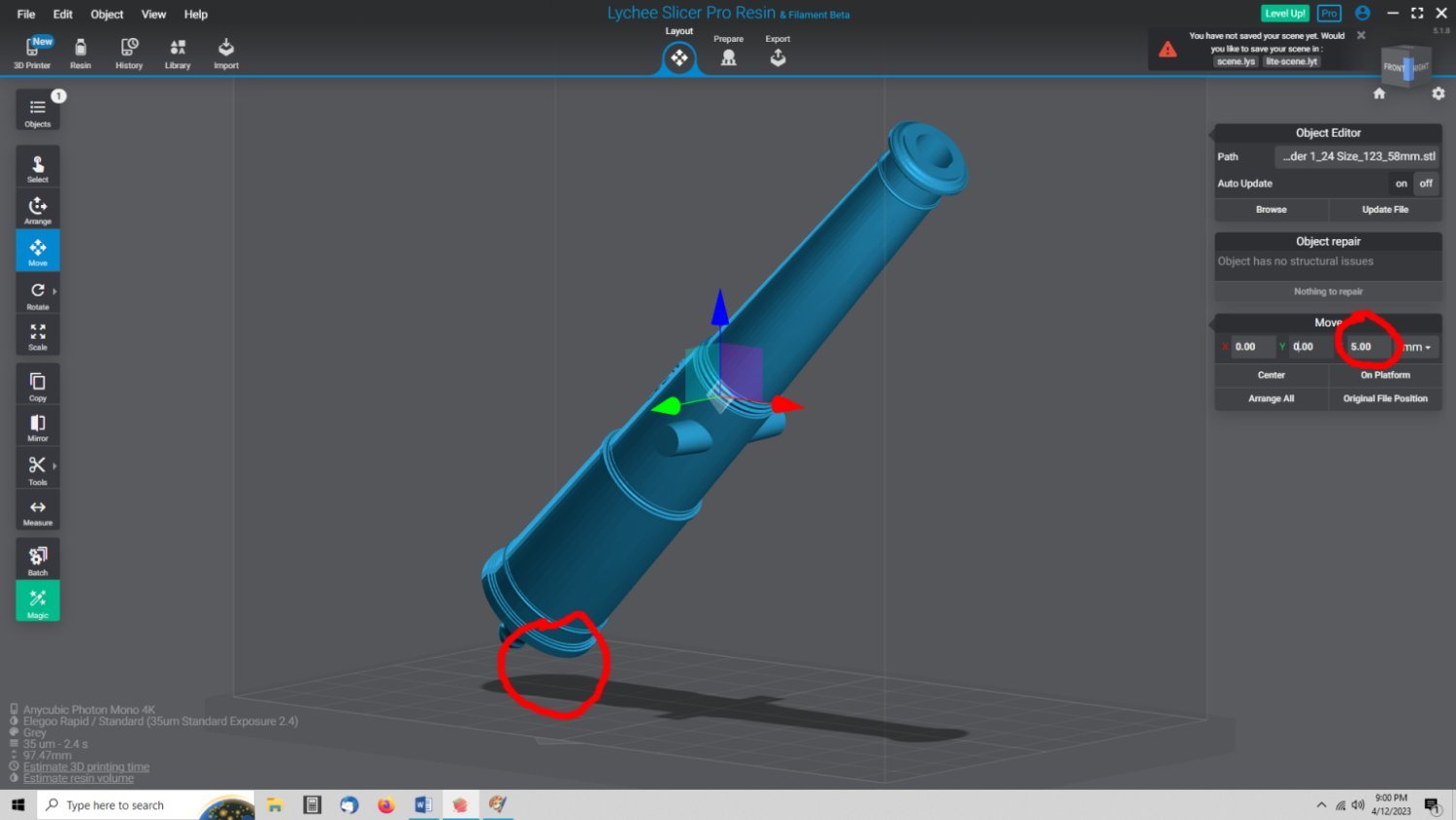
Next we have to elevate the model above the build plate surface to allow for the supports, and to clear the Raft we will be adding later (explained below).
I selected the “Move” button to start this operation, and raised the model 5mm on the Z axis. I find that 5mm works well for most prints. Less and you run into problems with the short initial supports, and longer just adds print time, and wasted resin.
Now that the model is where we want it, we can move onto creating the supports. Select the “Prepare” button at the top of the window
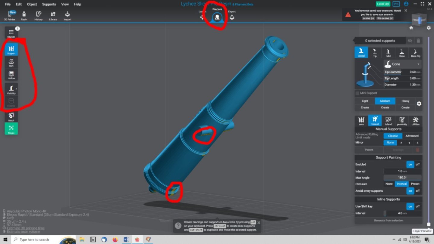
The left hand menu will change and a new set of windows will be displayed at the right. The program defaults to the “Support” option, but we need to add a raft first. Rafts are bases to the print that the bottoms of the supports attach to, to hold them onto the build plate. If you do not select a raft the program defaults to the circular ones shown in the right hand upper window. While these work, they have a problem. Remember the whole print will be stuck to the build plate, hopefully rather well, when the print is finished, and you will have to pry the print off of the plate to remove it! It is hard to get under these circles, which there will be a lot of, with the scraper. There is a superior raft that is available for your prints, and it is one of the options on both the free and paid versions. It looks like a shallow tray with splayed edges that are easy to get the edge of the scraper under, and generally allow you to remove the print as a single part. This prevents damage to the model from supports randomly breaking away from the model and perhaps breaking smaller sections off, before you could otherwise carefully remove the supports from these areas yourself.
In the picture above I’ve circled some Yellow areas on the model. These are island areas the program has detected. These areas will help you see if any additional areas need to have supports added, after we allow to program to auto-generate a set.
Here is an example of the supports with the default circle rafts.
First I will add the better raft as described above. I selected the “Raft” button and this screen is displayed.
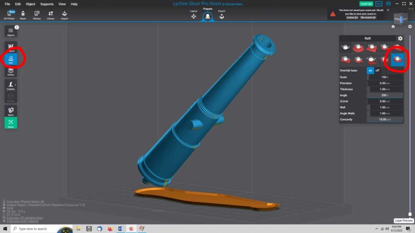
I then selected the raft circled on the right. I have never used any of the other styles, and don’t know what special cases they are good for, sorry. The raft is now shown under the cannon, In some cases, if your model is large, some of the raft area will be outside the print volume, this is OK, these areas will simply not print, but will not cause an error on your printer when you go to print. All the supports need to be within the print volume though.
Continued in Part 6.
-
Part 1
So, you want to 3D print some cannons, you have the files, but don’t know where to start. I hope this will help you get started.
You found a drawing of the cannons you need for your ship or diorama.
Unfortunately, you do not know how to make these into a 3D drawing. However, you have found someone who has already done this, and you are able to get copies of the STL or OBJ files (files that are formatted for 3D display or printing) from them). Where do you go next?.
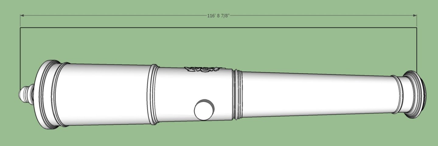
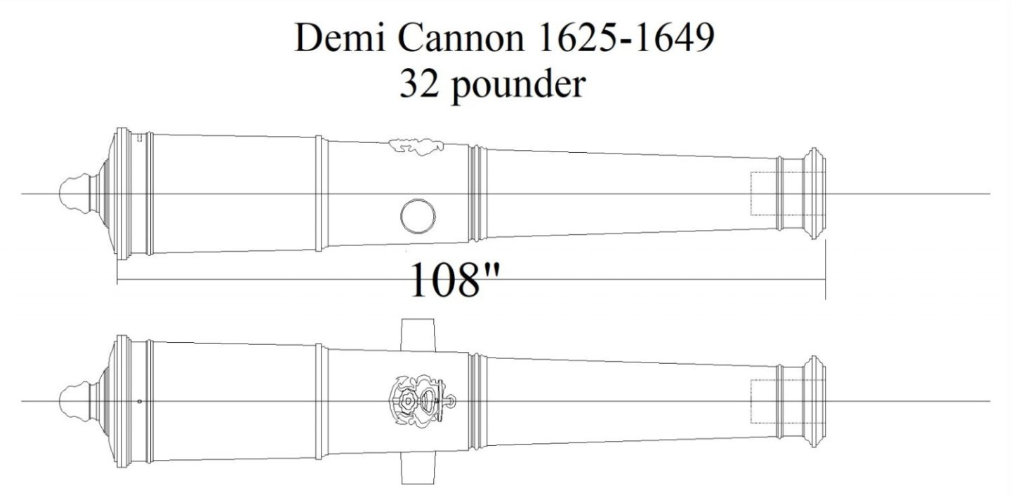
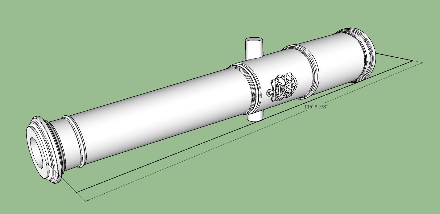
Below is an example of this cannon’s 3D drawing using the SketchUp program. Note that in the drawing above the dimension shown is from the end of the muzzle to the breach (bottom of the bore), while the dimension shown below is the overall length of the cannon.
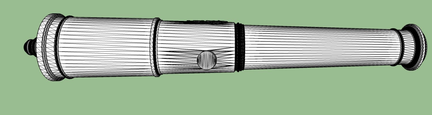
Here is a picture of the STL file for this cannon.
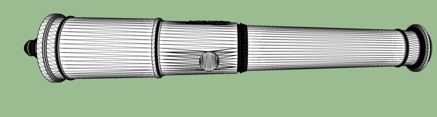
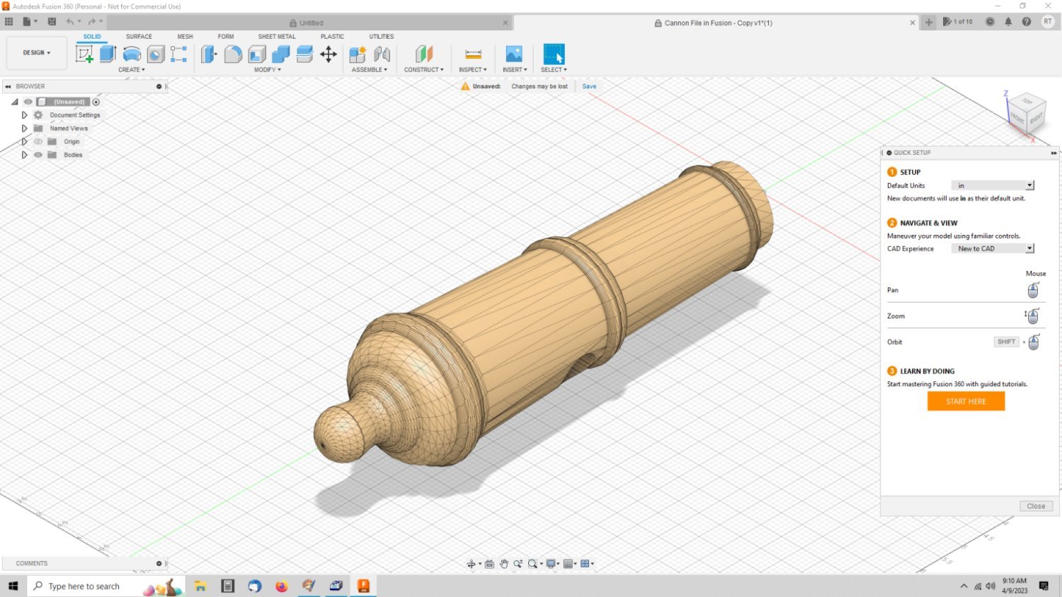
This is a screen shot of a different cannon, after a OBJ file has been generated from the original drawing in Fusion 360. Both OBJ and STL files have a similar format.

You can see that the cannons have been changed to a series of triangular surfaces. All the information on the size, orientation, location, etc., is what the STL/OBJ file contains. Programs can then convert this information into printer files.
Part 2
Let’s start with the simplest method. You have either a STL or OBJ file in the correct scale, and are sending it out to a commercial printer. It is best, but not required, if you know the correct length for the prototype cannon(s), so you can double check the final scaled dimensions. 3D printers almost always use the metric system, so you need to change that length to millimeters, if it is in feet/inches.
You and the printer can double check that you are getting the proper size cannons. The printer generally has a process for downloading the files to them. Follow those instructions, and let them do the rest. If your file is not in the correct scale, they generally allow you to change the dimensions before you hit the buy button. This is where knowing the correct length comes in really handy. Just putting in a ratio from one scale to the next, is not as accurate as entering a fixed length, due to the fact that they generally limit you to two decimal places in either case. For instance the file is full size, and you want them printed in 1/64th scale. For this example, your cannon is 100” long. So convert it to mm = 2540mm. If you divide by 64, you get 39.6875mm. Rounded to two decimal places, this is 39.69mm. Using the ratio method 1/64 = 0.015625, or a ratio of 0.02 when rounded to 2 decimal places. So 2540 X .0.02 = 50.8mm, not even close. Even if they allow three decimal places of accuracy in a scale ratio, you end up with a model cannon 39.624mm long, close but it still might be noticeable if you are trying to replace some damaged or missing cannons you already have, from say, a kit.
If you have someone who is willing to print them for you, and is willing to do all the setup, you just need to give them the file and the correct length, if you have it.
Part 3
Now we will take the route of either you are just starting out with 3D printing at home, or you have a friend that will print them for you, but does not have the time to do all the processing for you. Note, that it may take two or three trials to get the supports right, so allow for this.
For scale models with good detail, you need to use a resin 3D printer, the filament printers have much too course a “Line Size” for fine detail. The nozzle on a standard filament printer is 0.400mm, with a typical layer height of 0.200mm. A 3D resin printer, typically has a line width of 0.050 to 0.035mm, or less, with a layer height that can be set between 0.050mm and 0.010mm! So 10 times the resolution of a filament printer. The difference is like using thick cardboard layers and a wide felt tip pen, as opposed to layers of thin paper drawn with a sharp pencil. 3D resin printers need supports to print a model, as will be explained later, and these will leave tiny pock marks when removed, similar to injection molded parts, so you will have to paint the cannons, even if they are printed in black resin. You want to do this anyway, as UV light will degraded the resin, or any plastic for that matter, over time.
Both types of 3D printers need processing of the files, before they can print it. Basically the model has to be cut into many slices, as both printers build the model one layer at a time. The filament type printers build up the model by putting down layers of melted plastic, one on top of the other, going upwards from the base of the printer. While thin, these layers are, relative to a small model, quite thick, with visible stair step surfaces. These are great for large models, and for small assembly type parts, such as a new motor mount for re-motoring a model railroad engine, toys, servo mounts, etc. The plastics are more durable to shock loads than resin, which can be brittle.
Any 3D resin print will need supports, as will be explained later. Some 3D filament parts may also need supports, for complex shapes. For our cannons though, resin is the way to go, and I will only cover that method.
First you need to determine if the file is already scaled properly, or do you have to rescale it, because it either represents a full size drawing (1:1), or is the wrong scale (ie. The file is 1/48th scale and you need 1/64th).
You can rescale both STL and OBJ files in Lychee Slicer (one of the more popular (and free!) 3D printer slicers), but there are some checks I run in other programs that I will detail in later sections for these type files. Right now, we will just look at scaling in Lychee.
STL and OBJ files are the standard printable files that are most commonly available. The STL type is the printable file associated with SketchUp. SketchUp’s native file (the file it uses for saving its standard drawings is SKP, like AutoCAD’s DWG, or MS Word’s DOC or DOCX files). When the SketchUp file is finished, you output it to an STL file for 3D printing. Fusion 360 is similar, but its 3D print file is the OBJ file type.
Let’s assume that your file is in the incorrect scale, and you just want to rescale it. I will show you the simple way using Lychee Slicer. Lychee Slicer has a free version that can be down loaded
from https://mango3d.io/downloads/
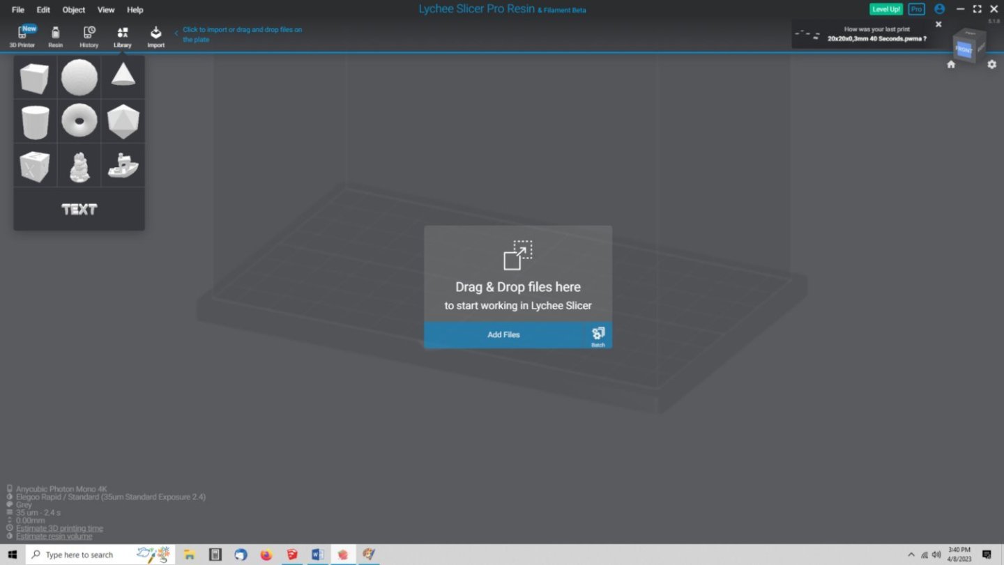
Open Lychee to import your file.
1. When you first start Lychee, you will get one of two screens.
a. If you have no prior projects started, or it is the first time you have run Lychee, you will get this screen. Simply select the Add File button and select your file.
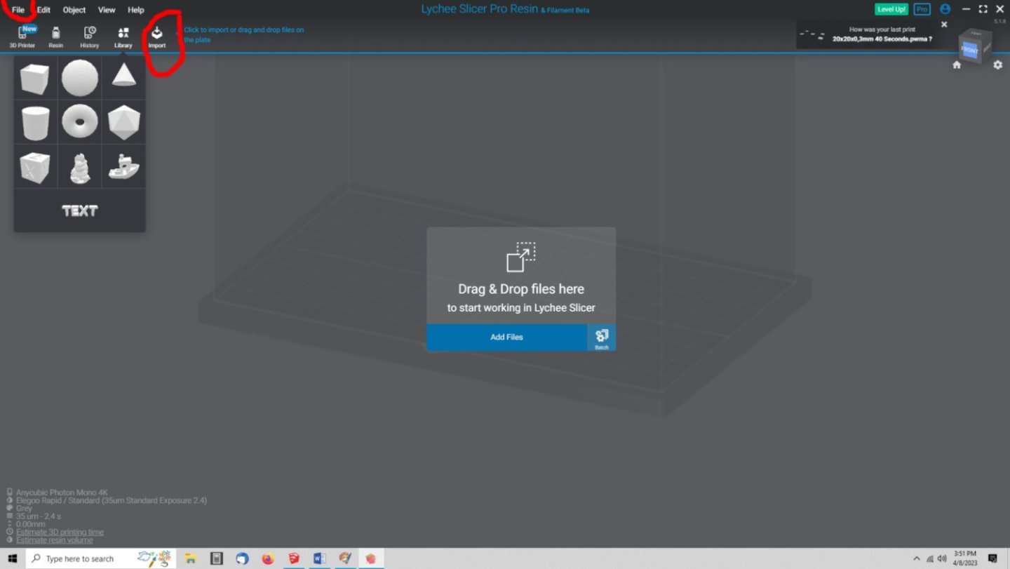
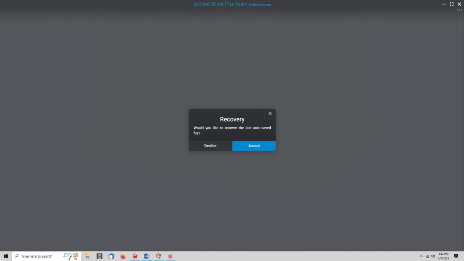
b. If you had a prior project running when you exited Lychee, you will get this screen, and probably can skip the rest of this section because you are familiar with it. Select “Decline”, and open your file either from the "Add Files" button, the "File" menu, or the "Import" button.

For this example I will be rescaling a 1/24th scale file to 1/64th scale. In the picture below, I’ve opened the file for a 6 Pounder British cannon from the early 1600s, that in full size is 98.8 inches or 2509.57 mm long, or 104.56mm long in 1/24th scale.
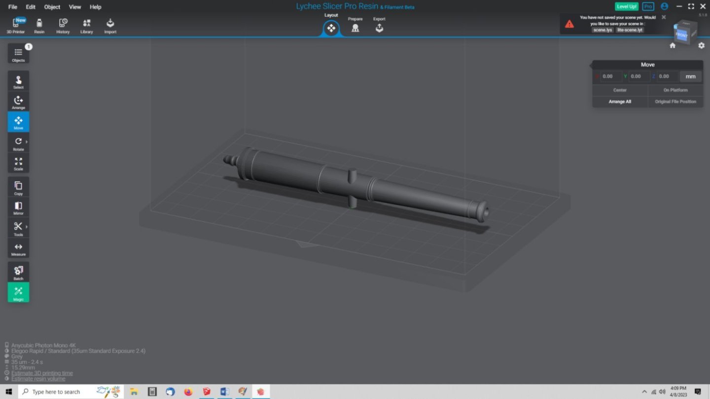
Notice that the cannon is gray, if it comes in light or dark red, there is a problem with the file. Generally it means there is a hole somewhere in the object. This can generally be corrected in Lychee.
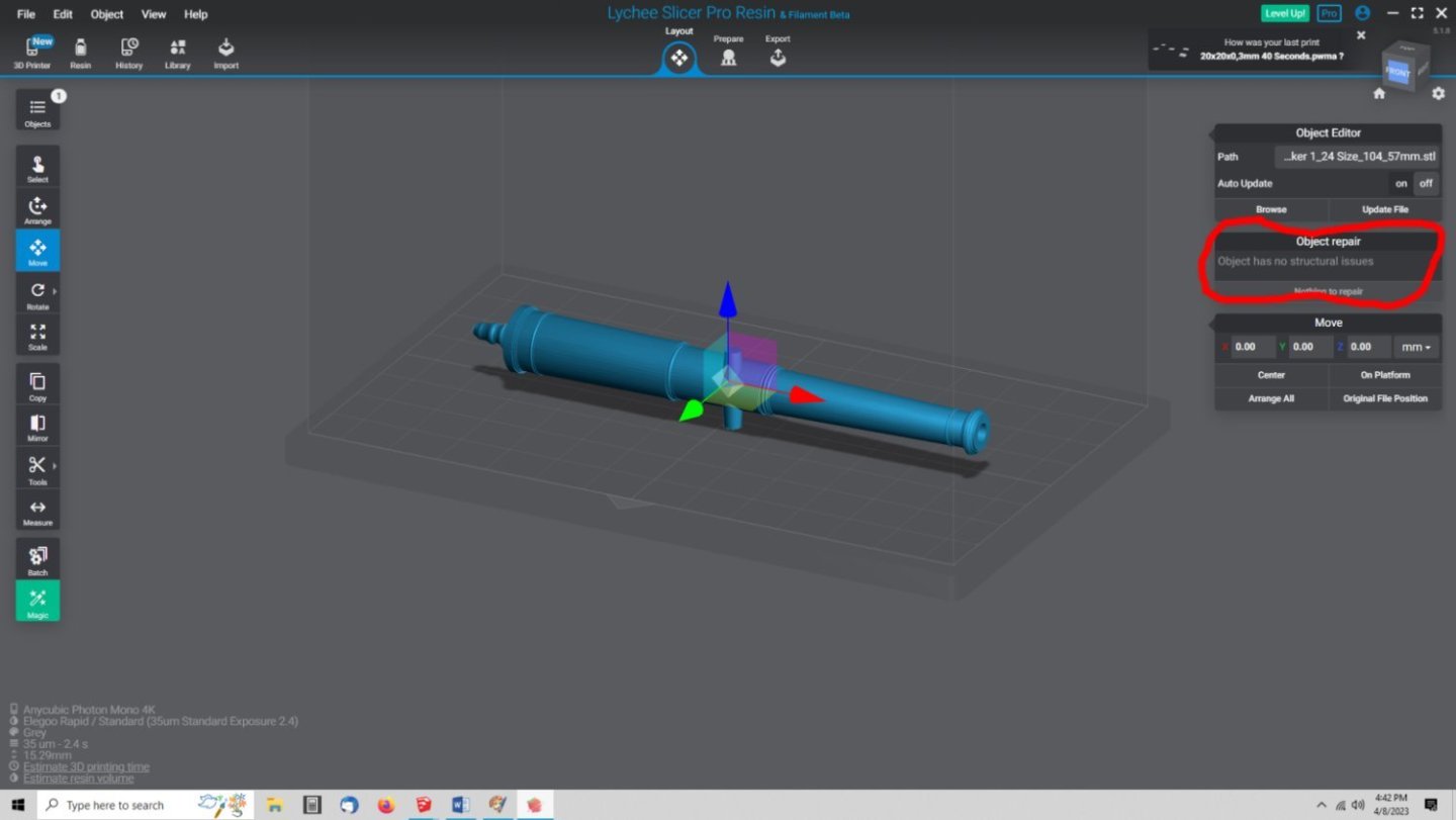
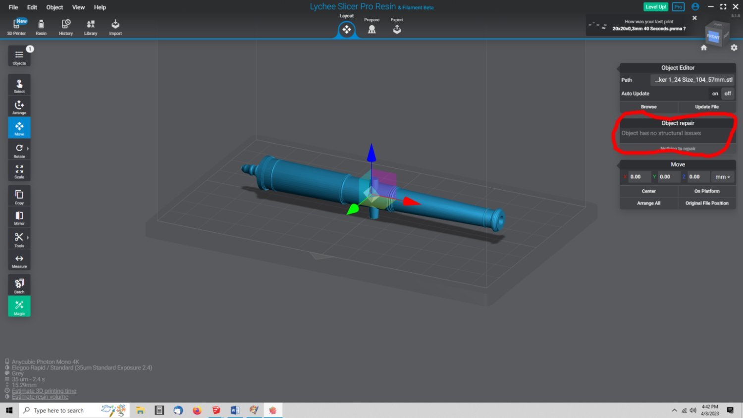
If it is gray click on the cannon, and the “Object Repair” window should say everything is Ok, continue. If not see directly below.
The window displayed if there are no errors with the model.
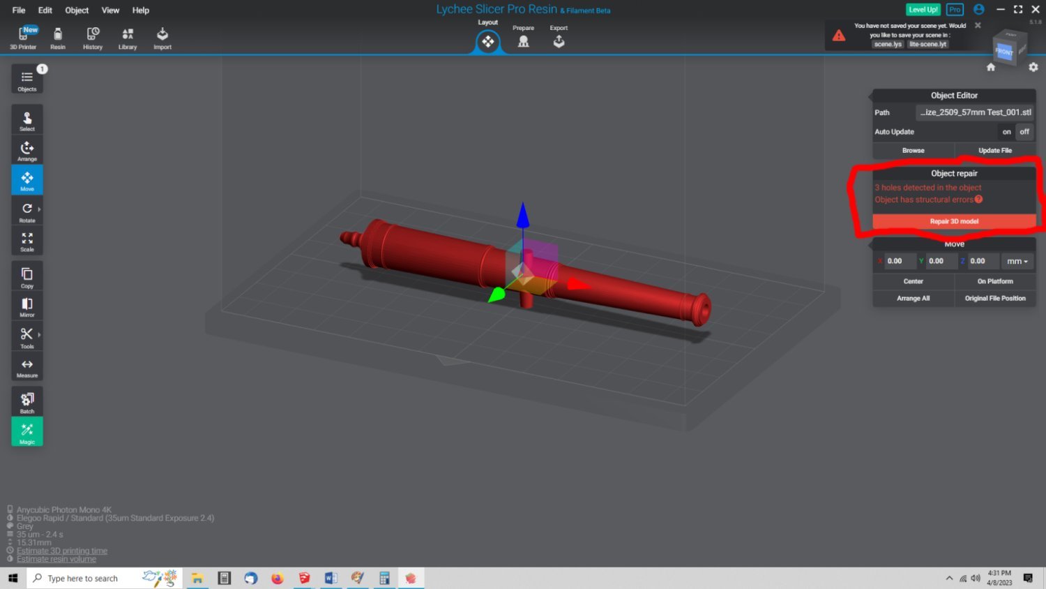
The file below has a problem, that must be corrected before you can continue.

In this case click on the object.

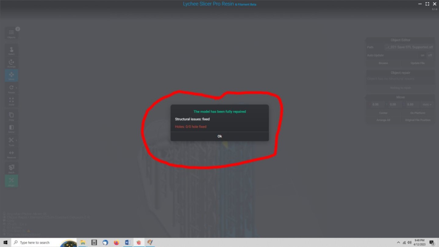
You will see the Object Repair pop-up at the right. Select “Repair 3D model”, and let the program fix it. In this case the problem could not be fixed. Go to the Netfabb Section, to see how to repair the problem. Otherwise Lychee will fix the problem, and tell you it did. You can now go to the scaling function.
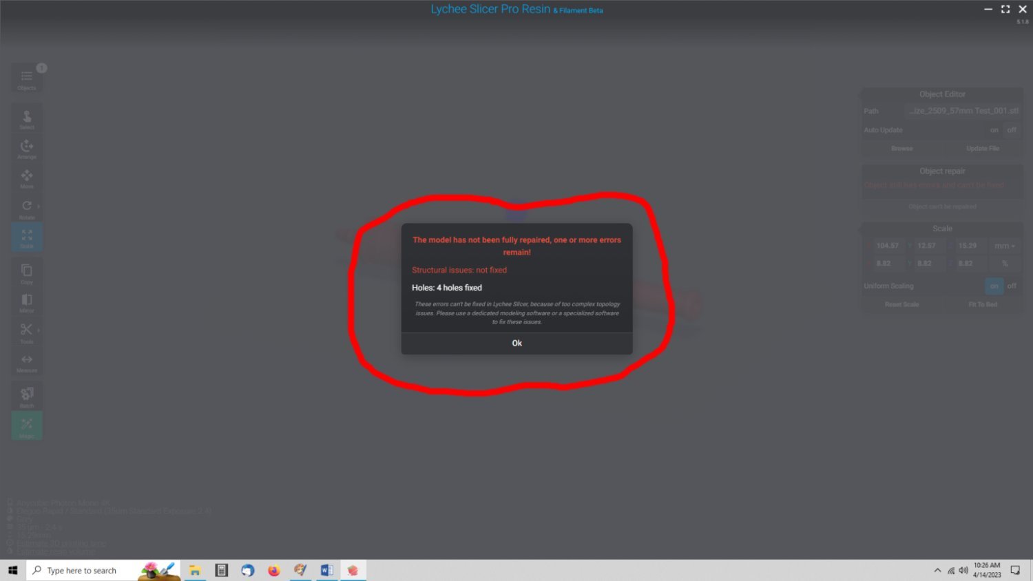
This is the window that will be displayed, if the repair fails.

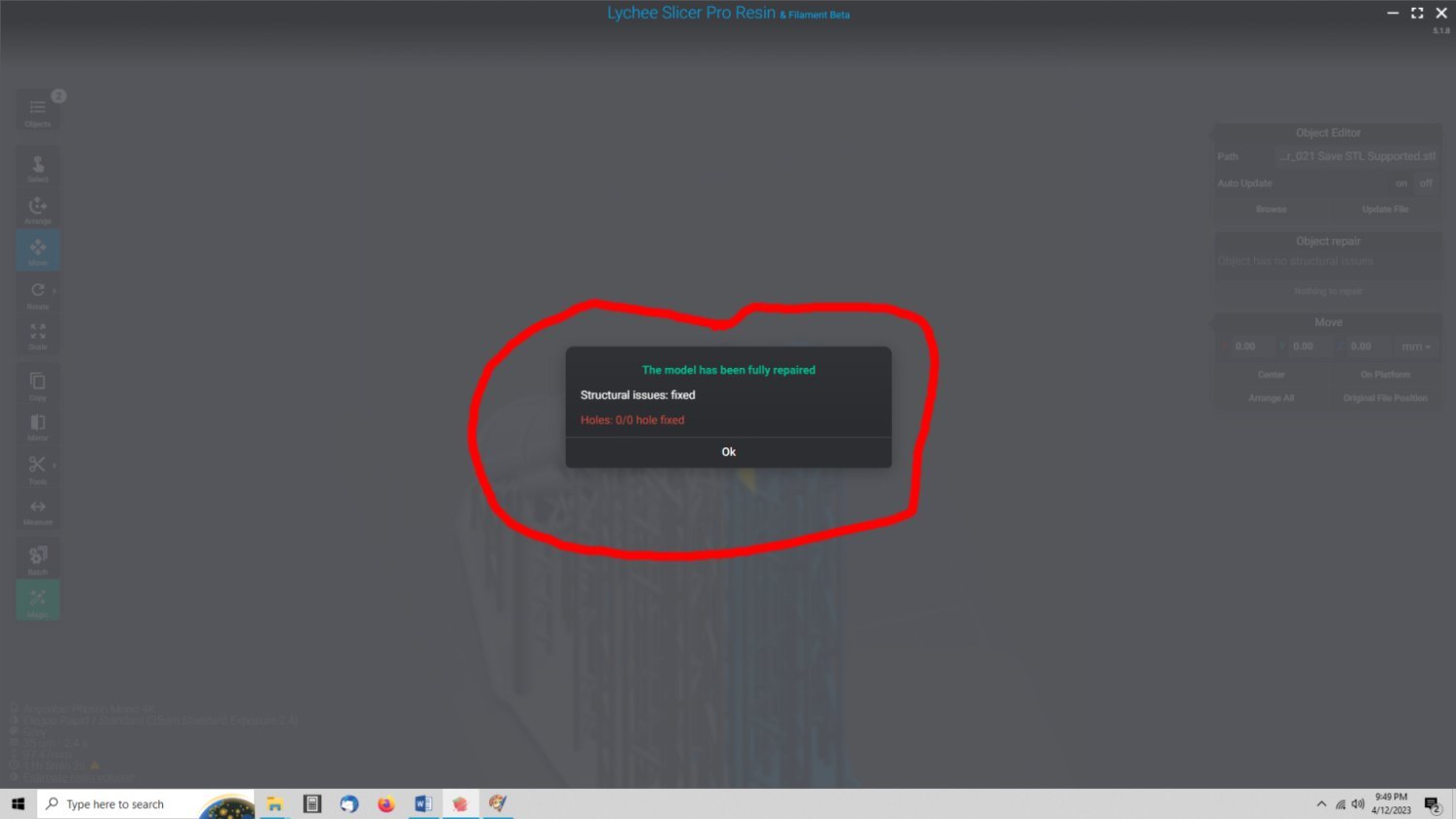
This is the window displayed if the model could be fixed. Yes, if you look closely this is from a different model. I know someone out there will notice it.
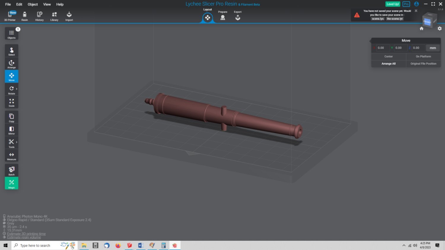
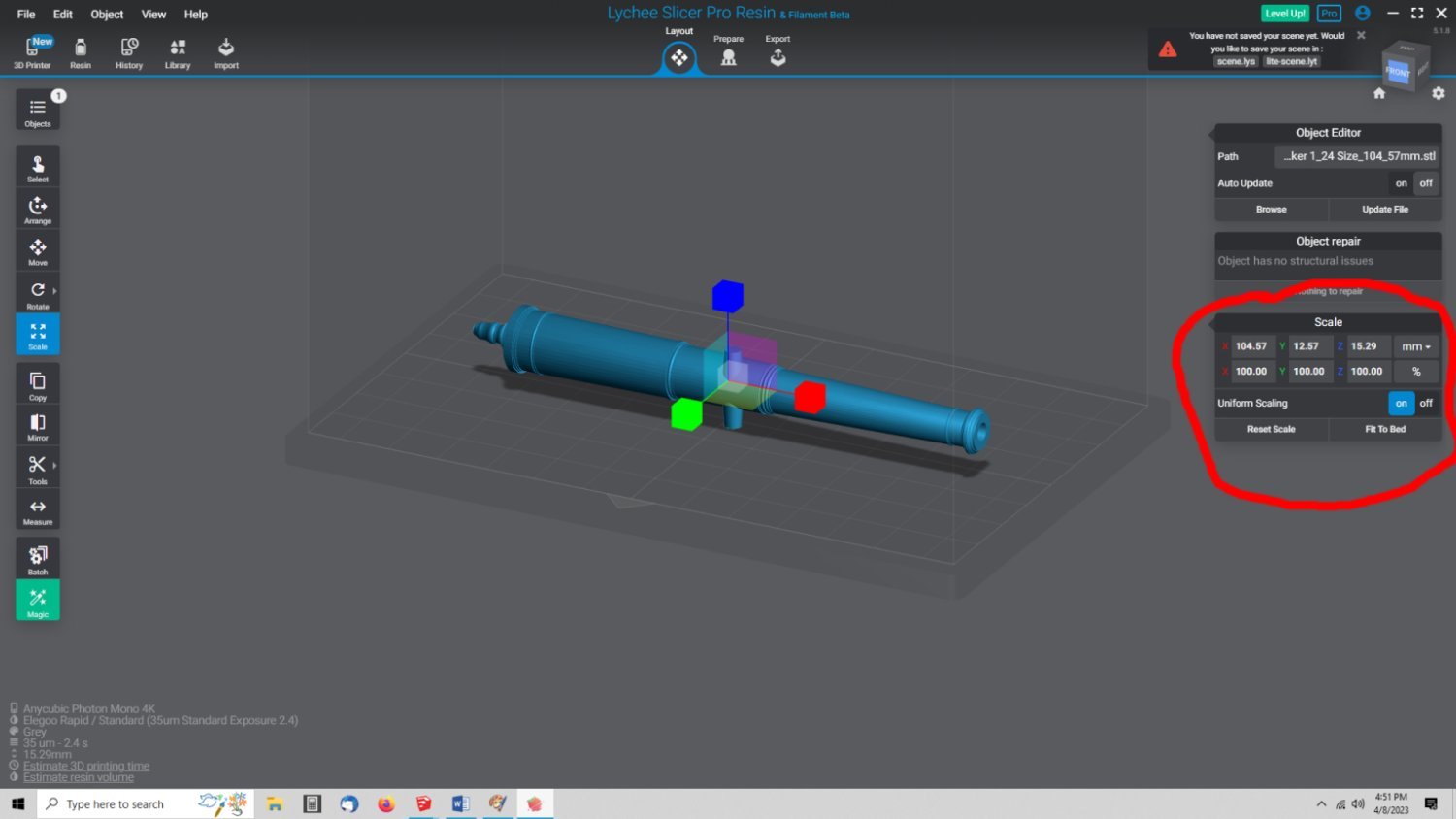
If there were no problems, the object will be blue. On the left, select the Scale button.
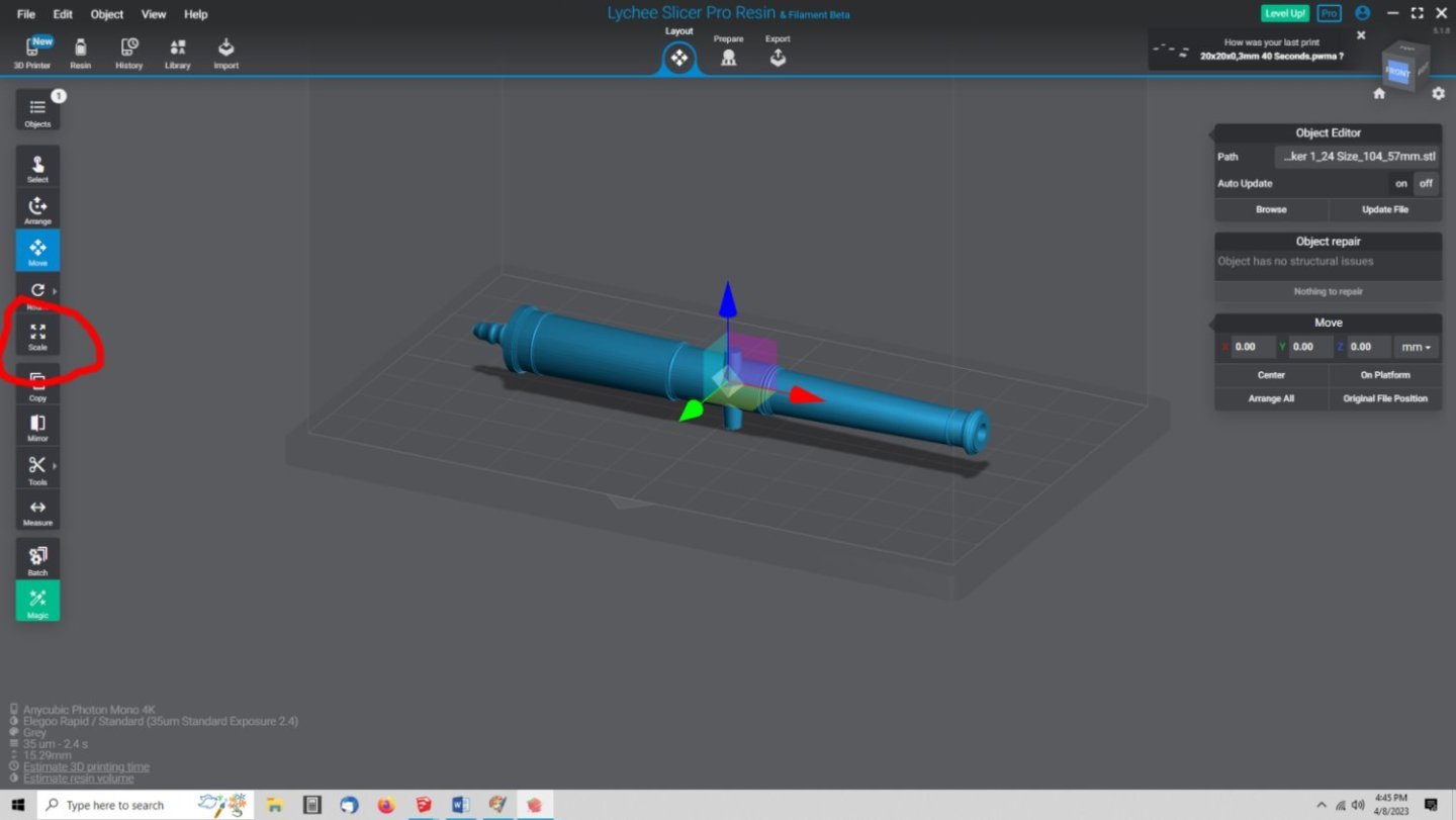
The Scale Window will open.

First, make sure that the “Uniform Scaling" button is selected to “ON”. With this on, any change you make to the dimension of one axis, with be automatically re-scaled for the other two. With the button “OFF” you would have to scale X, Y, and Z separately.
So, the scaling window shows that the 1/24thth scale model is 104.57mm long. The full size length of the real cannon was 2509.57mm, which is a better number to scale from, if you have it. For example, 2509.57/24 = 104.5654, which rounds up to 104.57mm, but if you re-scale from 1/24th to 1/64th, you may be off by a little due to the rounding.
Anyway, for this write up I will use the full length value for determining the correct length for 1/64th scale 2509.57/64 = 39.212mm, or 39.21mm after rounding.
In the “Scaling Window” enter this value into the “X” box, and then select one of the other (Y or Z) boxes. Lychee will now re-scale the whole cannon to 1/64th scale. You will see that the model is now shown smaller on the screen.
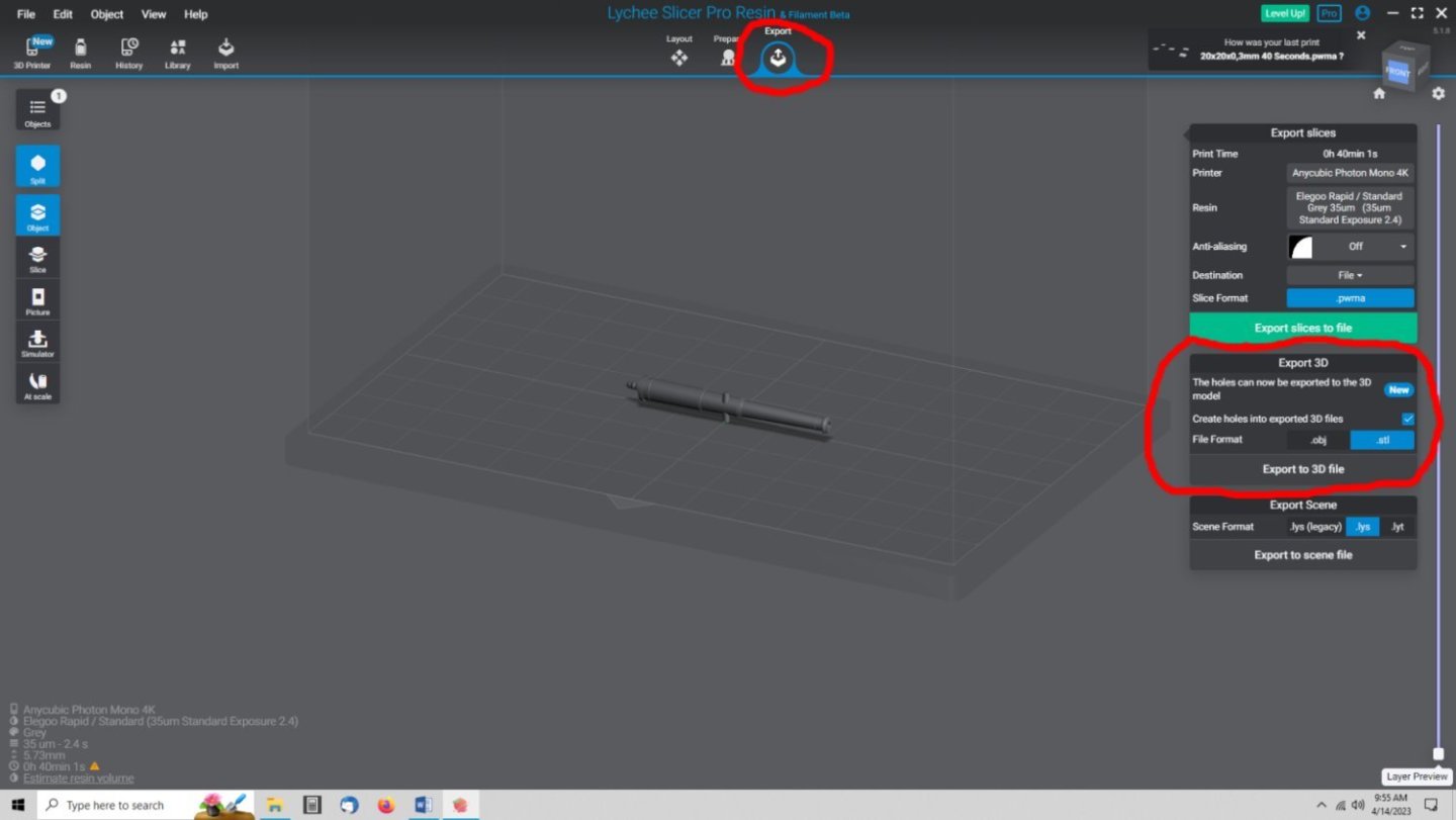
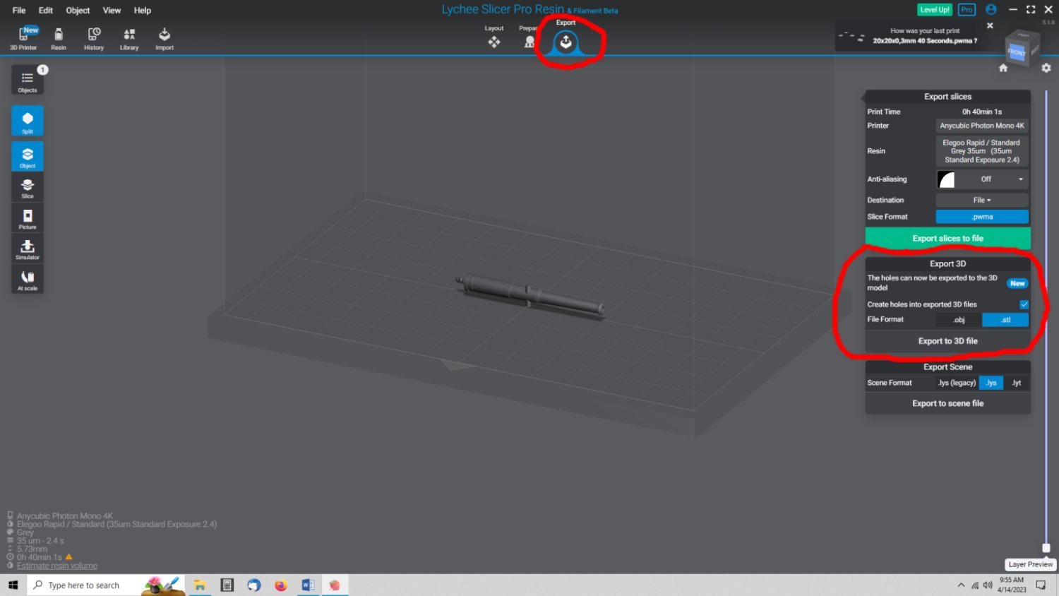
Select the “Export” button at the top of the screen. A set of windows will open in the right hand side of the window. Select the “Export to 3D File” button, and follow the prompts, to save the file. Saving the file is covered in more detail towards the end of Part 5.
-
-
-
-
-
-
How do you want me to send the files?
- mtaylor and Old Collingwood
-
 2
2
-
I have 4 files for a 6 wheel passenger truck model I purchased that are in SolidWorks .sldprt format, that I need converted to the SKP file type. Does anyone have SolidWorks, that could help me?
I need to modify this truck to a Santa Fe specific 4 wheel truck. The other file format that was in the download was the STL type, that while I can edit it, is difficult to do so.
- Old Collingwood and mtaylor
-
2
-
-
I bought the series of books on the San Juan whaling vessel, a great read!
- Canute, mtaylor and Roger Pellett
-
3
-
I've been CADing several early 17th century British cannons for a project, and I just finished printing out the first test set of the 6 and 9 pounders (long and short barrel) in 1/24th scale. It took almost 24 hours at 35um layer heights, but the files checked out! Presently the 18 and 24 pounders are printing. I will have to reprint the first set, as I did not have the supports all correctly set up, but the cannons printed OK, so the original STL files are good. I just need to add a few more supports for the final printed set. These prints are for my use, to go on display along with my 1/24th Model Expo Naval Cannon displays. The barrels and cypher emblem came out well, but the trunions are warped. I also have to figure a way to better clean the bore and touch hole out as some resin was still in them, and caused blemishes when I cured them. That is the great thing about resin printers, I can just make another set.
The lighting is poor on the picture, as I had to go with ambient lighting. The flash washed out all the detailing, at such a close distance. The longest cannon is a little less than 5" long, in this scale.

-
I'm CADing a set of Brown Pattern Cannons 1625 to 1649 for a project, and figured I might as well 3D print myself a set, also. I have the old Model Expo Naval Cannon kits, and These printed in the same 1/24th scale would make a nice co-display
with them. I have tried to find information on the carriages, with little success. Even "Arming and Fitting of English Ships of War, 1600-1815" has just a drawing for one from "A small ship" and an old woodcut that has a weird drawing style.
Does anyone have better information? The cannons I'm drawing run from 6 to 32 Pounders. Is there any information on carriage size to gun size that I could scale drawings to? Even latter era data may allow me to make SWAGs.
- Keith Black and mtaylor
-
2
-
If using pure water based acrylic paints, don't use IPA! Tamyia(sp) paints have a alcohol base, so the above might work with them, but all others react badly to IPA! For these others you use IPA as a cleaner, not as a thinner. Adding the IPA to these types of paint, is like adding lacquer thinner to enamels. The IPA will either cause premature drying, or prevent adhesion. The other three ingredients can be used with most acrylics, but the Flow improver and retarder are better added to the bottle airbrush cup as you use it and in small quantities..
-
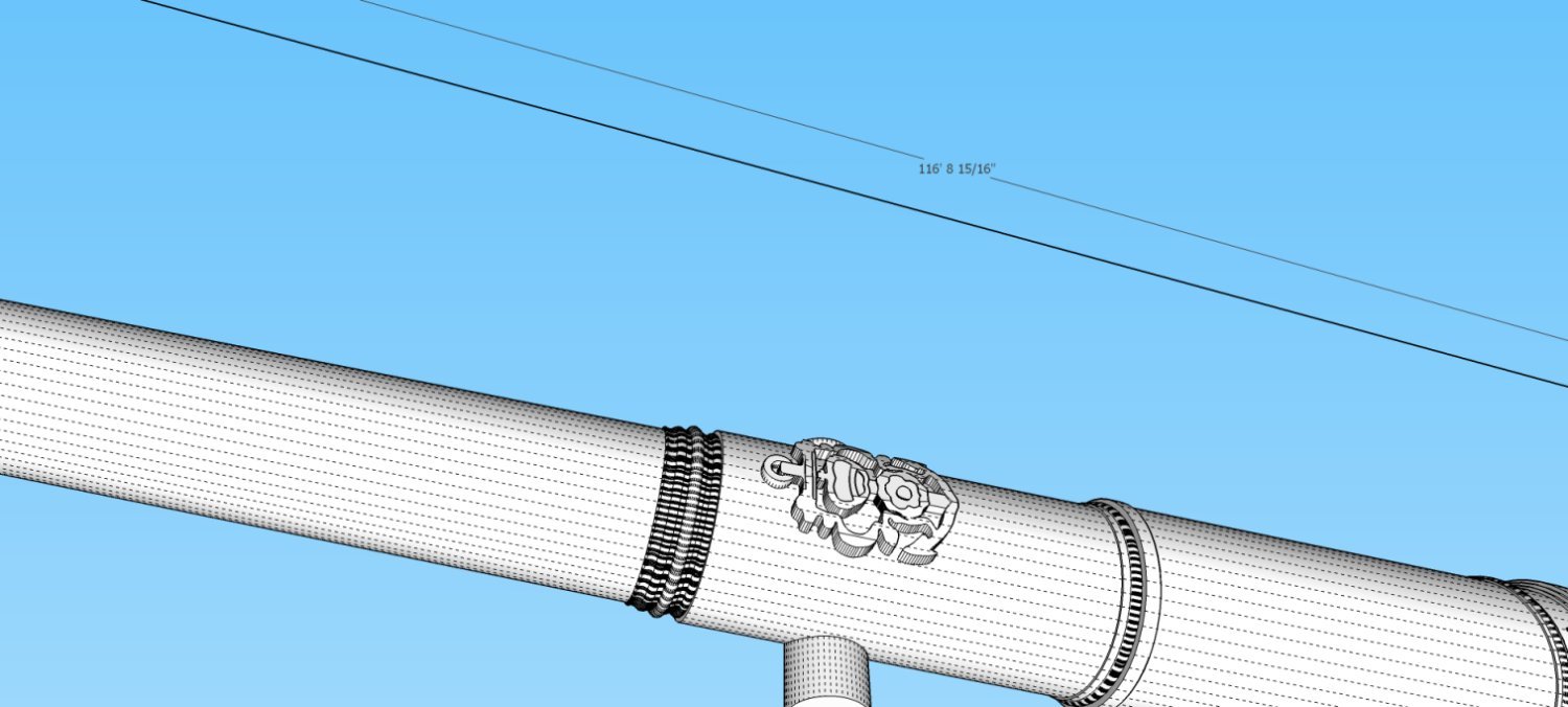
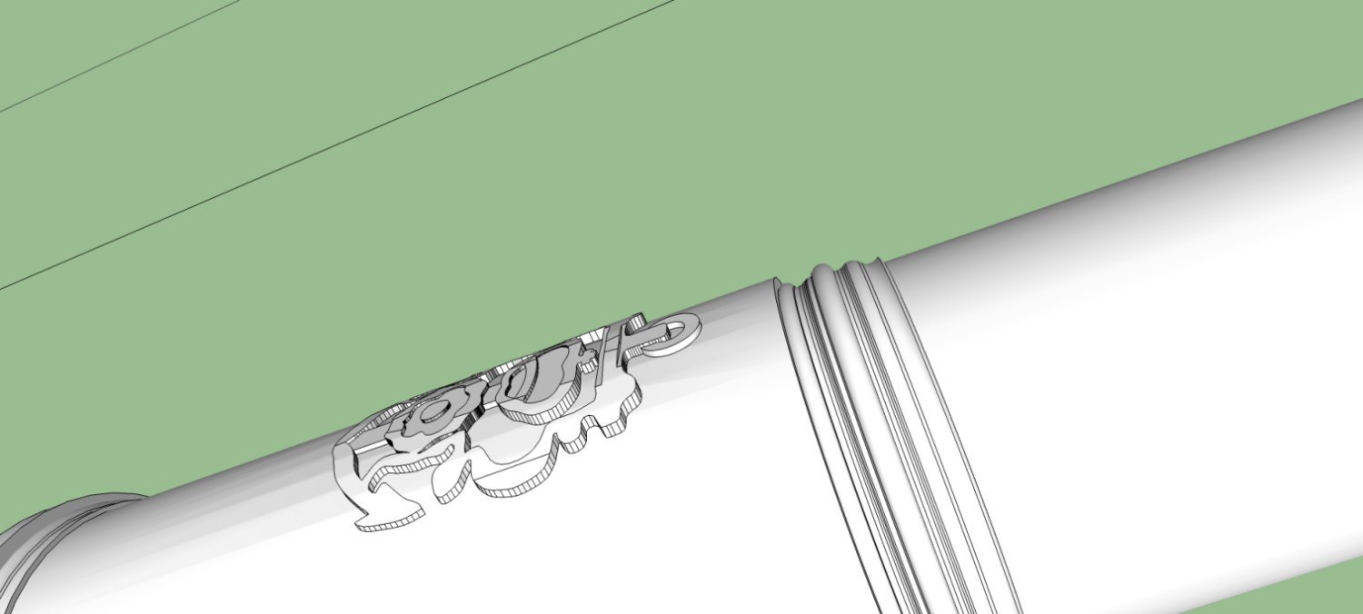
Unfortunately, my present camera, will not focus on these small prints, I did of my cannons for this project, but I can give some results from my first prints. Here are graphics of the two heights I tried. My cypher was shown on the drawings as the one I used, not the Royal Seal from the posts above. Please ignore the length shown in the taller cypher graphic. Due to limitations in SketchUp, I do all my drawings in feet (in equivalent to full size inches) and inches, instead of full size inches. So the 166 foot 8+ inches, really scales to ~166 + inches, when I'm done. SketchUp does not like items that are smaller than about 1/32 inch when you draw directly in just inches, which makes small items like the cypher difficult to work with. I rescale the model in Netfab, when I create the STL files.
I printed one of each cannon in 1/48th, 1/64th, 1/72nd, and 1/96th. They were printed on an Anycubic Mono 4K with a 35um pixel size and at a 35um layer height.
In any case, the taller cypher scales out to 1/2" tall at the anchor ring, and 1" over all. The lower one scales to 1/8" and 1/4" respectively.


When I printed them the tall cypher stood up way too much, for the three larger scales, but was still clear, if still too tall at 1/96th. The lower cypher looked better with the shorter offset for 1/48 to 1/72nd, but was almost invisible at 1/96th. At all the scales even this lower resolution cypher is lacking in visible detail, but can still be recognized, due to printer limitations.
I had a couple of the cannons fail, but my FEP needs replacement, of the cannons that did print (and stayed on the base), these are the best pictures I was able to get.
The first is the cannon with the lower offset cypher at 1/64th scale. The second is the taller offset cypher at 1/64, 1/72, and 1/96. The lower offset cypher looks more reasonable for those on a real cannon.
-
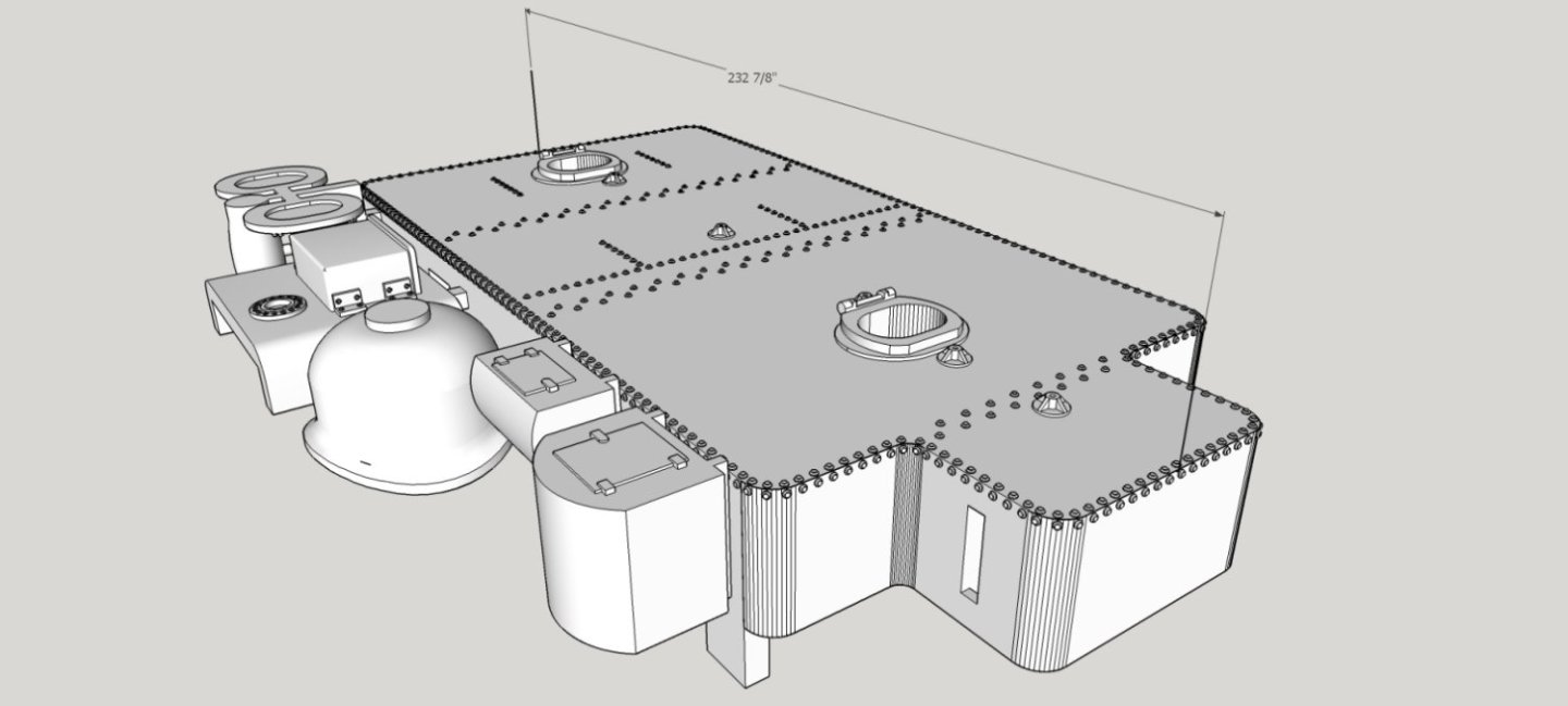
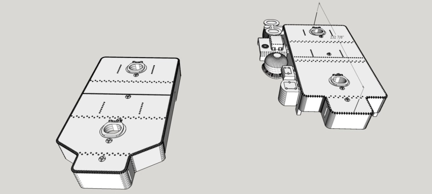
I spent the last few days drafting the frame for the Superintendent’s Car. The frame is finished as far as the major assemblies. I’ll add the various levers, equipment boxes, tanks, etc. as separate pieces, and as I get more information on items like the brake system. The pictures of the frame show two strap assemblies. These also are separate parts, and will be printed as such. I had to draw them in place, though, to get the proper angles, so I’m showing them as if installed. I still have to place the blocks for mounting the couplers, but will do that after I’ve printed and assembled a car. I have a set of the correct type trucks for another car, so I can make the proper measurements using them.
I initially drew the frame members overlong, and the floor overlong and too wide. Then I placed the frame in place under the sides and ends, and marked the areas that needed to be cut. This saved a lot of detailed measuring, and gives me a perfect fit.
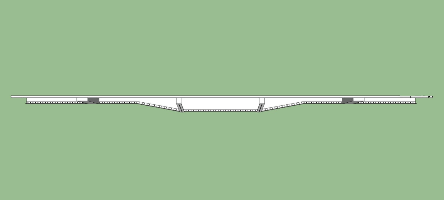
This is the frame from the side, with the straps.
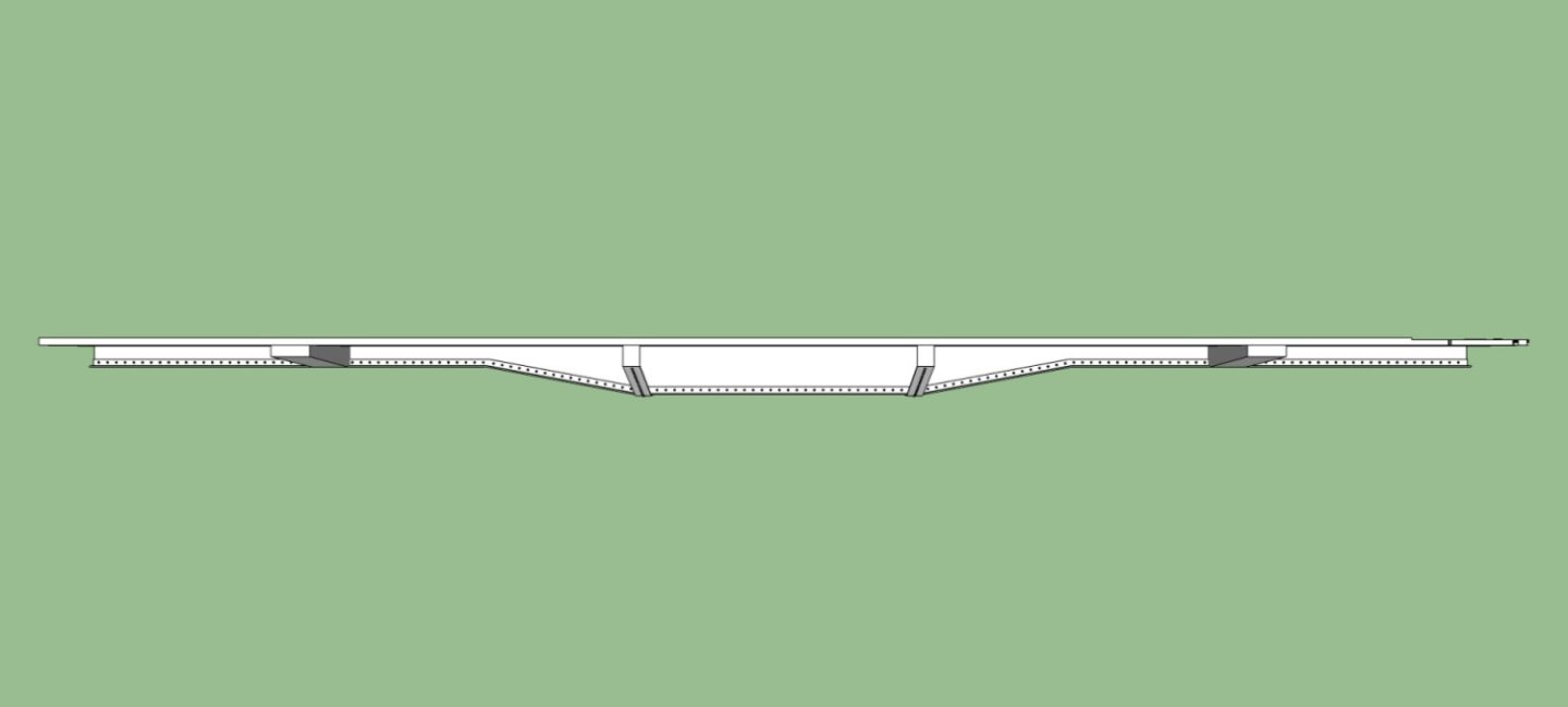
And two others showing some close-up details. Lots of rivets.


This picture shows the frame in place, with a close-up of the observation platform. The various bosses at the end of the platform are mounts for the railings. This platform area sits a few inches lower than the interior floor.
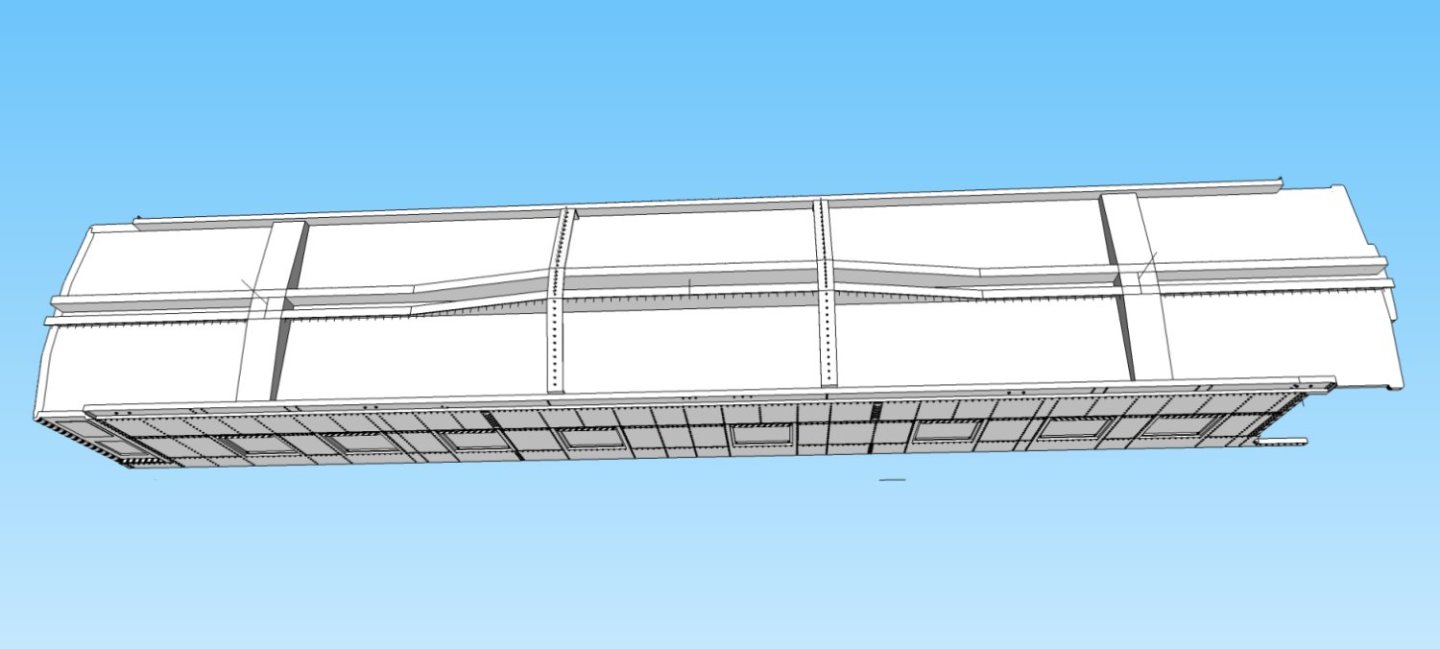
The last picture shows the assembly from the underside.
I volunteered to draft some of the cannons for the NRG Cannon project, and will turn my efforts to them for a while, then start on the complex roof for this car, and any other Pullman Heavyweight passenger cars I may tackle in the future.
-
Yes. SketchUp 2017. For future projects, I may have to switch to another software package, as I recently found out that I can no longer install addons (extensions) due to security concerns and lack of available ones that work with my version! Even though in December, most of them were compatible and were offered by 3rd party vendors!
-
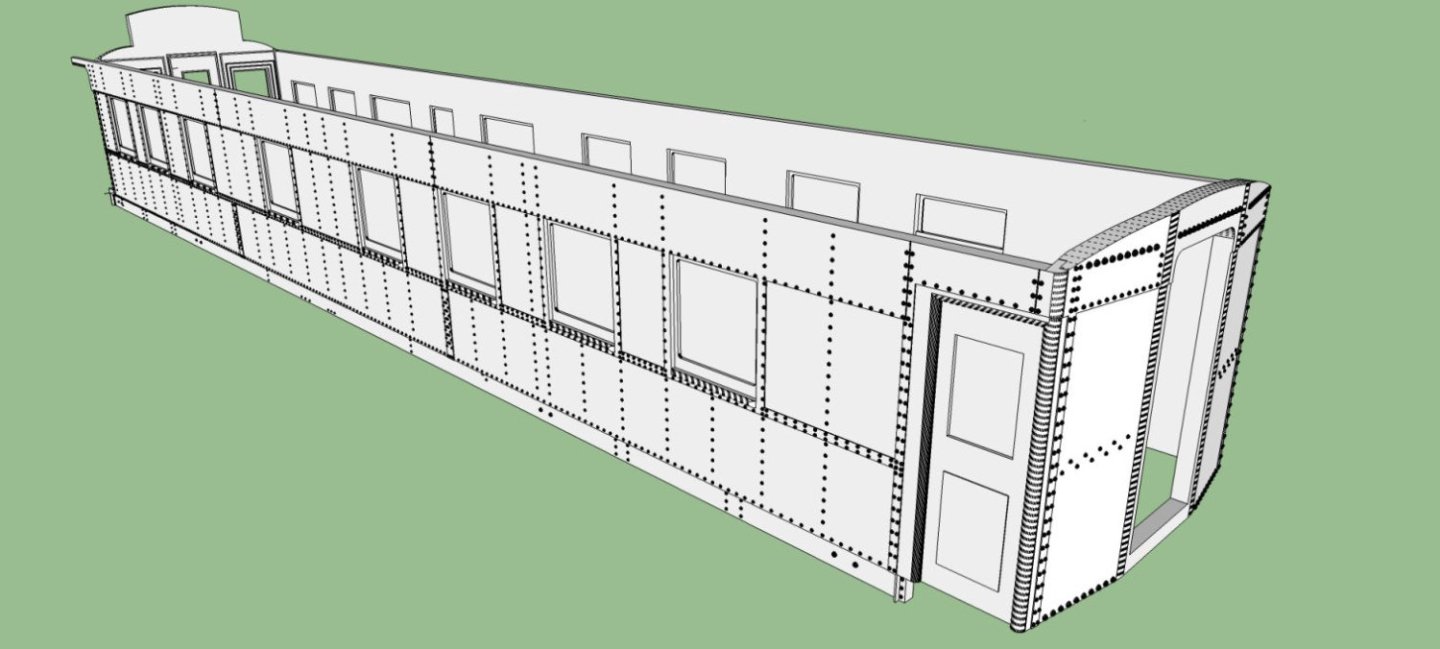
Well after a couple years I finally finished mostly) the 3D body for my Santa Fe Superintendent’s Car! The drafting would not have taken so long, but I kept finding better references, to correct detail mistakes in the original drawing I used. The drawing was well done, but was hand drafted by a modeler over 50 years ago, and the hundreds of rivets laid out on it were not always correctly placed. Also many details were not clear, without the photographs I found from various internet sources. Next will be the underframe, roof, and interior. For now I have a donor car for the underframe and roof to make a mockup.
Here are a few views of the CAD file.
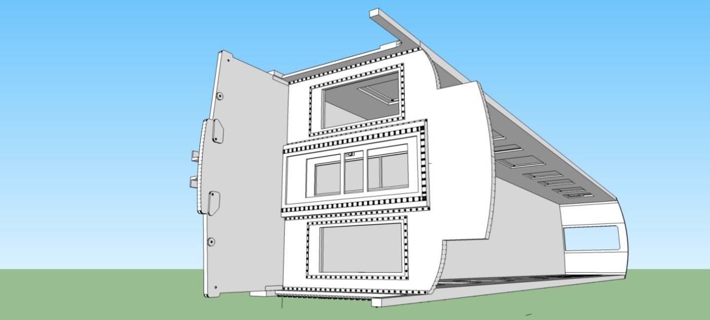
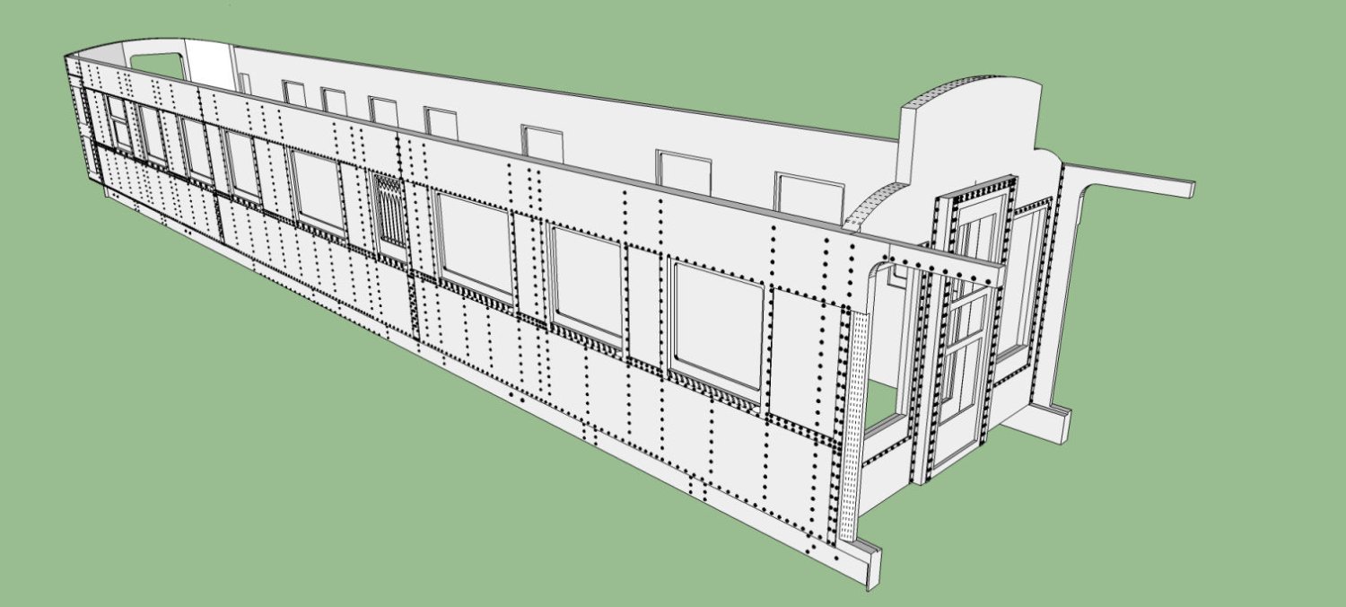
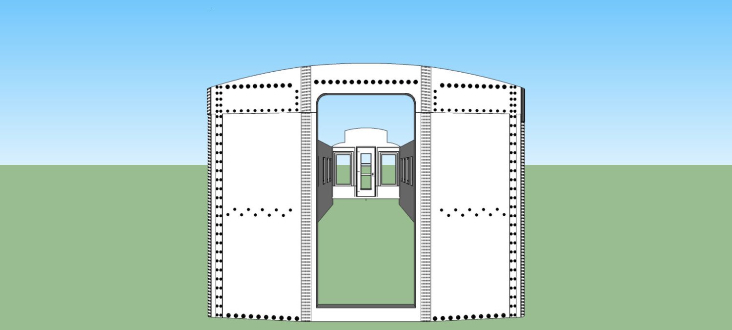
First a perspective view from the front of the car. Note that the front wall/vestibule is and angled surface, making placing the rivets interesting. The window glass is filled in here as support during printing. I am rethinking the way that the final window glass/ frames will be designed. They may be a separate assembly that pushes in from the rear.
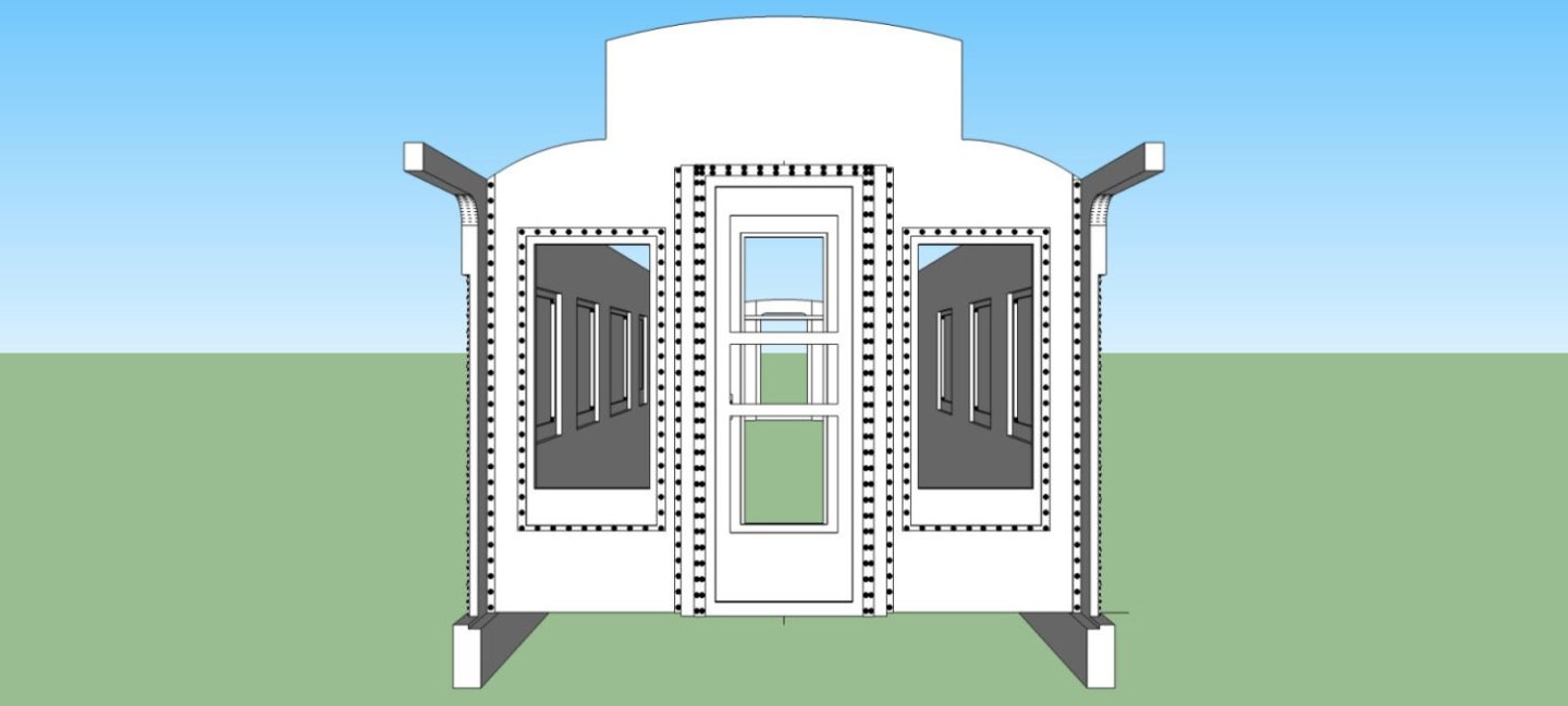
Next is a similar view from the back of the car. If you look closely, you will notice that it has a main door and a screen door. The main door is a separate piece, and will not be printed in place, as shown here. This lets me install both the main door windows and the screening on the screen door. This wall is set into groves in the side walls to locate it.

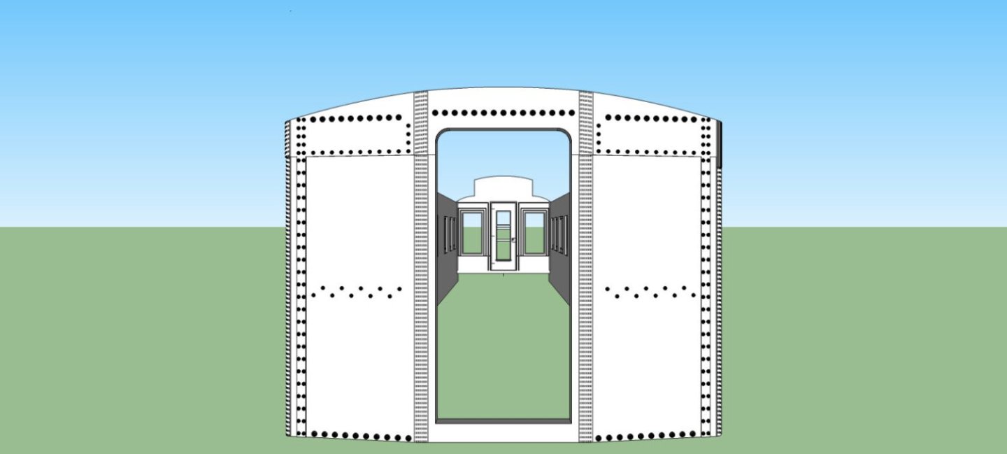
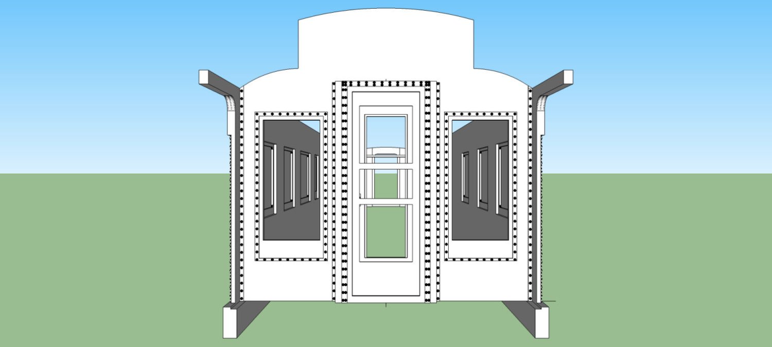
Next is a view of the observation end of the car. There will be an observation platform/porch floor, designed into the underframe. The roof line shown will likely change after the prototype roof is drafted. The roof line shown on the wall marches the interior lines of the donor car.
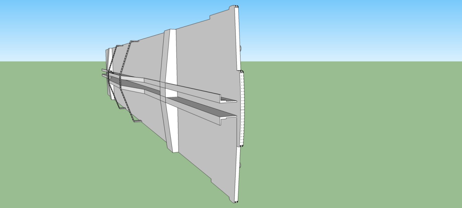
This is the front/vestibule wall. This wall fits into matching ledges in the side walls. You can see the inside observation main door at the other end of the car. The inside of the observation wall also has the interior trim.
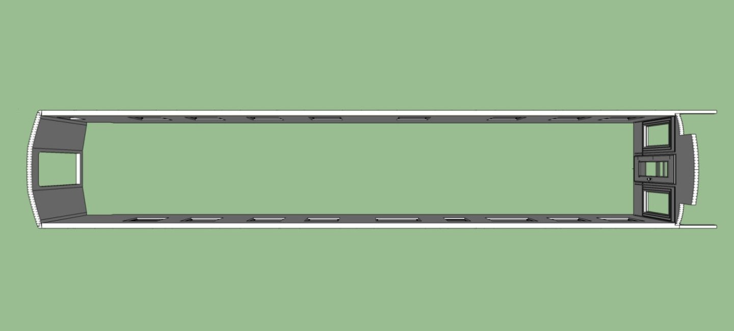
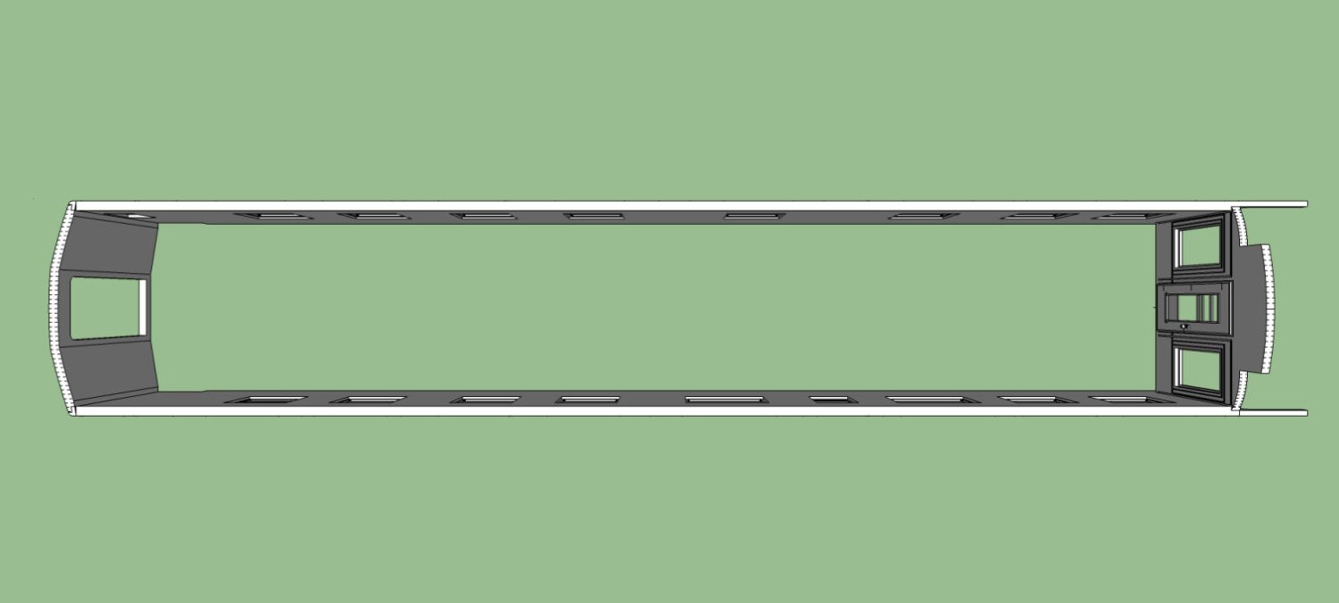
This is a top view of the body. You can see the angling of the outside of the vestibule wall, as well as the locating ledges between the four walls.
I also redesigned the tender oil bunker I drew several years ago. Most of it was correct, but when I placed the rivets I spaced them too closely. I used 1 1/2 inch spacing as I had to guess, having found no info on this. I found out late last year it should have been 3” spacing. I bought reprints of 10 years of the old “Santa Fe Modeler” magazines, and found the new (too me) information in them.
I’ve gotten a 3D print of this latest version from Shapeways and will be fitting it to my 2-8-0 tender in the next week, or so. I was planning on 3D printing it at home, but I still haven’t got the supports right, it keeps distorting during printing. Once I verify the fit, I’ll offer it through Shapeways, as it will be more readily available to the public.
The next Oil Bunker project is to convert a Bachmann 2-10-0’s tender to oil. This is much more of a SWAG, as there are only a handful of under exposed photos of these. Santa Fe acquired the locomotives from a smaller railroad it purchased, and did not use them for very long. They were too small for most of their operations, and in poor repair. Hence the lack of pictures.
The old 2-10-0 bunker is on the left, and the new 2-8-0 version on the right. You can see the difference between the old and new rivet spacing.
- mtaylor, Prowler901 and Montaigne
-
3
-
For those of you (like me) who use the free 2017 version of SketchUp (the last one that let you do all the work on your computer, not online through them), they have disabled the Extension Warehouse feature, due to "Security Concerns". This even though 90% of the offered extensions still worked with that version.
I'll have to back up my operating system onto another drive in case mine dies, My files are far to large to do them over the net, even if I wanted to allow SketchUp, or someone hacking them, access to them.
-
The copper/iron problem, as at the beginning of the era of coppering. the ships were built with iron fasteners, and when the copper plates were first used on these ships, the galvanic action did bad things to the original ship's fasteners. I don't remember the complete solution, but they did find ways to prevent this. I think it was a combination of adding a intervening layer of wood to the hull between the ship's bottom and the plating, and using bronze fasteners on new ships.
-
Were you using Tamiya Thinner? The Tamiya paints are alcohol based, the Vallejo paints are water based, which should not be thinned with alcohol. The alcohol causes them the dry rapidly, at best, and can cause the paint to fail. Alcohol is one of the things you use to clean your airbrush when using Vallejo. Get some of Vallejo thinner (preferred), or use distilled water.
-
I have the Red Bay book set too. Quite interesting.
- Baker, Roger Pellett and mtaylor
-
3
-
I've spent more for a book. If you need info on an unusual (to the general public) subject, you pay what you need. I try to get used books, but sometimes even they are not cheap! I just bought a book on the Santa Fe's first passenger diesels the "One Spot Twins", for $75 used, and it was the cheapest, one of the copies was over $150. Depends on your needs. Other times I've gotten $75 books used for $10, luck of the draw.
- Baker, Ferrus Manus, druxey and 1 other
-
4
-
Welcome aboard!
- Dave_E, mtaylor, Knocklouder and 1 other
-
4


3D Printing Cannons in Resin
in 3D-Printing and Laser-Cutting.
Posted · Edited by thibaultron
Part 6
Now we need to go back to the Supports function, so I selected the “Prepare” button.
New windows are displayed on the right hand side of the display. Make sure that the “Auto” button is selected. I go with the default support types, at the top of the upper window.
As you can see, there are three options for support size: “Light”, Medium”, and “Heavy”. The larger the support size, the larger the surface area of the interface between the support tip and the model, thus, the larger the potential mark/divot removing the support can make. So you have to go for the smallest support to model size possible.
Below are three pictures of the supported model, using each of the three support sizes. All three options generated about the same number of supports, about 100 to 105.
Light supports.
Medium supports.
Heavy Supports.
For smaller cannon, I would go with Light supports for the auto generated ones, but for this large model, I would pick the Medium supports. The Heavy supports are overkill and may make for really visible defects that need to be fixed. In addition, if you look closely at the heavy support graphic, you can see that there are visible internal supports in the bore of the cannon. While not visible in the other two graphics, they too have these internal supports. The internal heavy supports may be difficult to break out, while the light and medium supports can be removed by running a dowel or other small object down the bore. With a model this large, I would not trust the light supports to function well.
Now we have to look to see if additional supports are needed. In short, yes. I have found that the trunnions need more support than the Auto Generate function provides. Looking at the model, you can see large island areas at the bottom of the trunnions, with no or just a single support for these areas. In my experience, the trunnions are either missing this island area, leaving a flat spot, and many times also distorted. I remove any present supports in these areas, and add my own just past the barrel-trunnion junction and on at the outside end of the trunnion. For these added supports, I go with the next larger size, so, since I chose the medium supports, I would add heavy supports in these spots. The bottom of the trunnion will be hidden between the carriage and the cannon, so any divots will be almost invisible and easy to fix, If these were exposed surfaces, I might opt to stay with the medium supports. Later I will show you how I handled the thin screw handles on the other type of cannons I mentioned in the first section.
The next graphic shows the other side of the supported model. In this picture, you can see one of the internal supports inside the bore. Ignore the one white colored support, my mouse pointer just happened to be on it, when I took the screen shot.
We need to fix the trunnion supports now.
First we need to remove any existing supports in the area, as they might interfere with placing the new ones.
Select the “Manual” button, this allows you to place and remove supports by hand. Next place the mouse pointer on the support to be removed. It will highlight in white. Then right click and the “Tags” window will pop-up. Select the “Remove Selected Support(s)” button, or hit the Delete Key, and the support will be removed.
This graphic shows the trunnion with all supports removed. Left click the mouse off of the model, to close the “Tags” window.
Now we have to add in the new supports. Re-select the model. As you move the pointer around the model you will see a phantom support following the pointer. You will also see a white horizontal line following it. This line shows you what level the tip of the support is at. You can use this line to find the exact bottom of the island, or a similar area on the level. The graphic shows the tip of the phantom support right at the bottom of the trunnion.
Left click, and the support will be placed. Note that in the previous graphic, I had forgotten to select the heavy support option, so I had to delete that support, select the “Heavy” button, and redo it. The graphic below shows the placed support. I added another support just outboard of the trunnion barrel junction.
I then repeated the operations on the other trunnion.
I did not remove the medium supports on this side, as I’m using this model simply to generate the screen shots. If I was doing this on an actual model I would have, as well as adding the support near the barrel-trunnion junction.
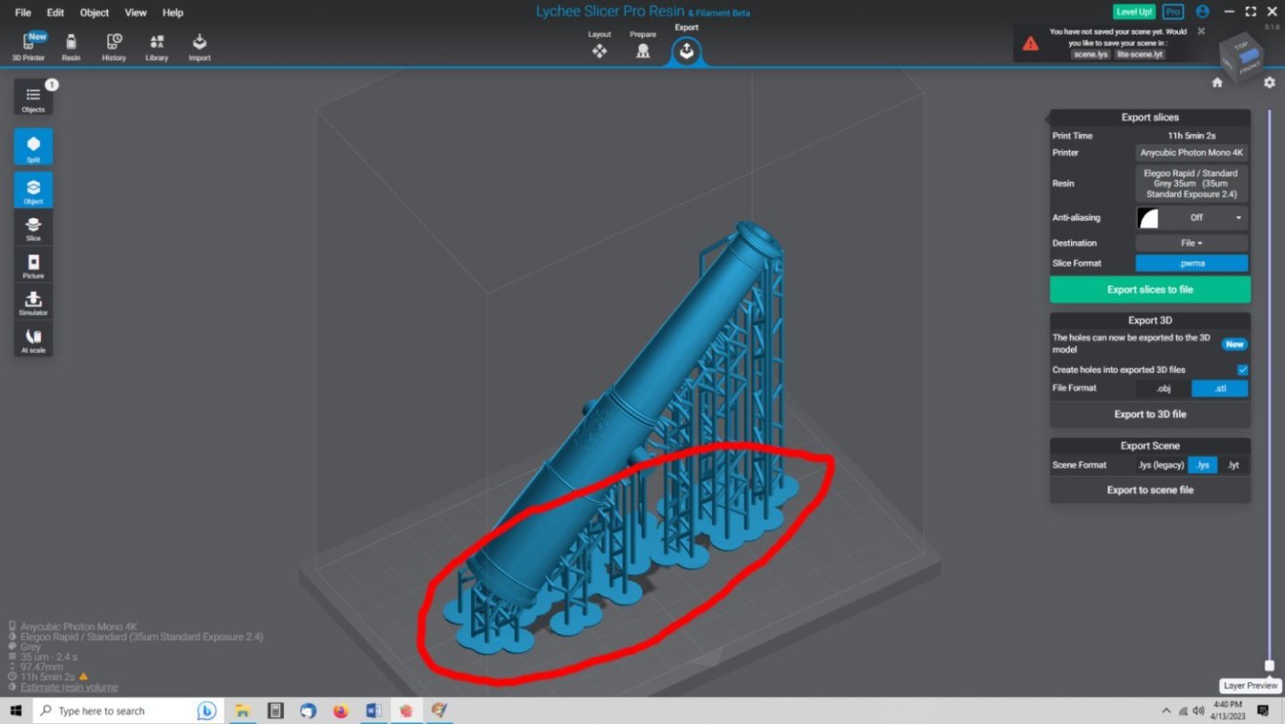
I also added some medium supports at a couple of spots on the bottom of the barrel, where islands were still shown in yellow. See the circled area below. Unfortunately, those screen shots got messed up, and when I redid the model to try to get the pictures, Lychee had placed supports there this time. This also shows that if you don’t like the first set of supports delete them and try again. If you have not gotten too far you can “Crtl Z” back to the pre-support model.
Continued in Part 7.