


thibaultron
-
Posts
2,637 -
Joined
-
Last visited
Content Type
Profiles
Forums
Gallery
Events
Posts posted by thibaultron
-
-
3 hours ago, Kauz said:
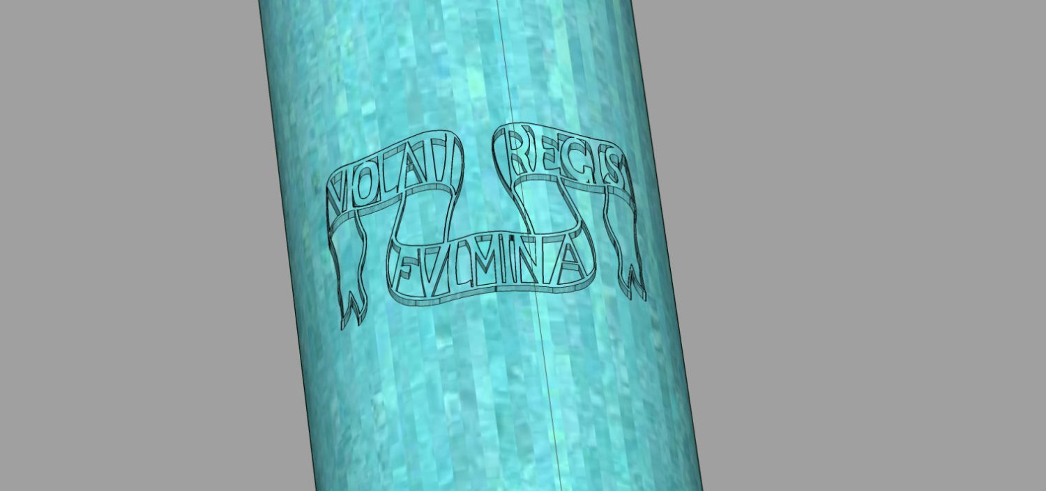
Actually, it translates as: "thunderbolts of the (an) insulted king".
Seems Google mistook "fulmina" for "femina", the latter meaning "woman".
😉
Than
Thanks for the correction!
-
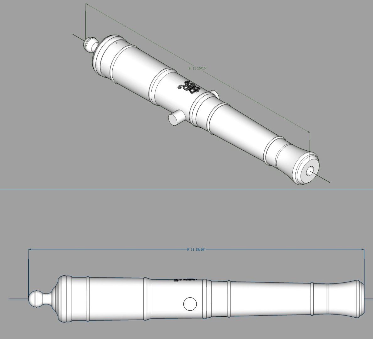
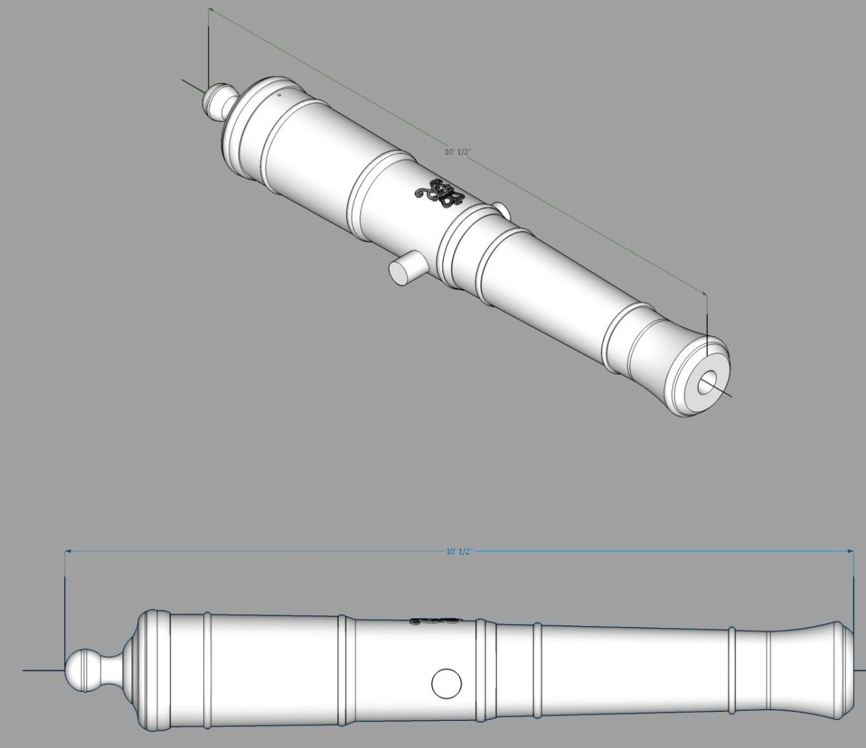
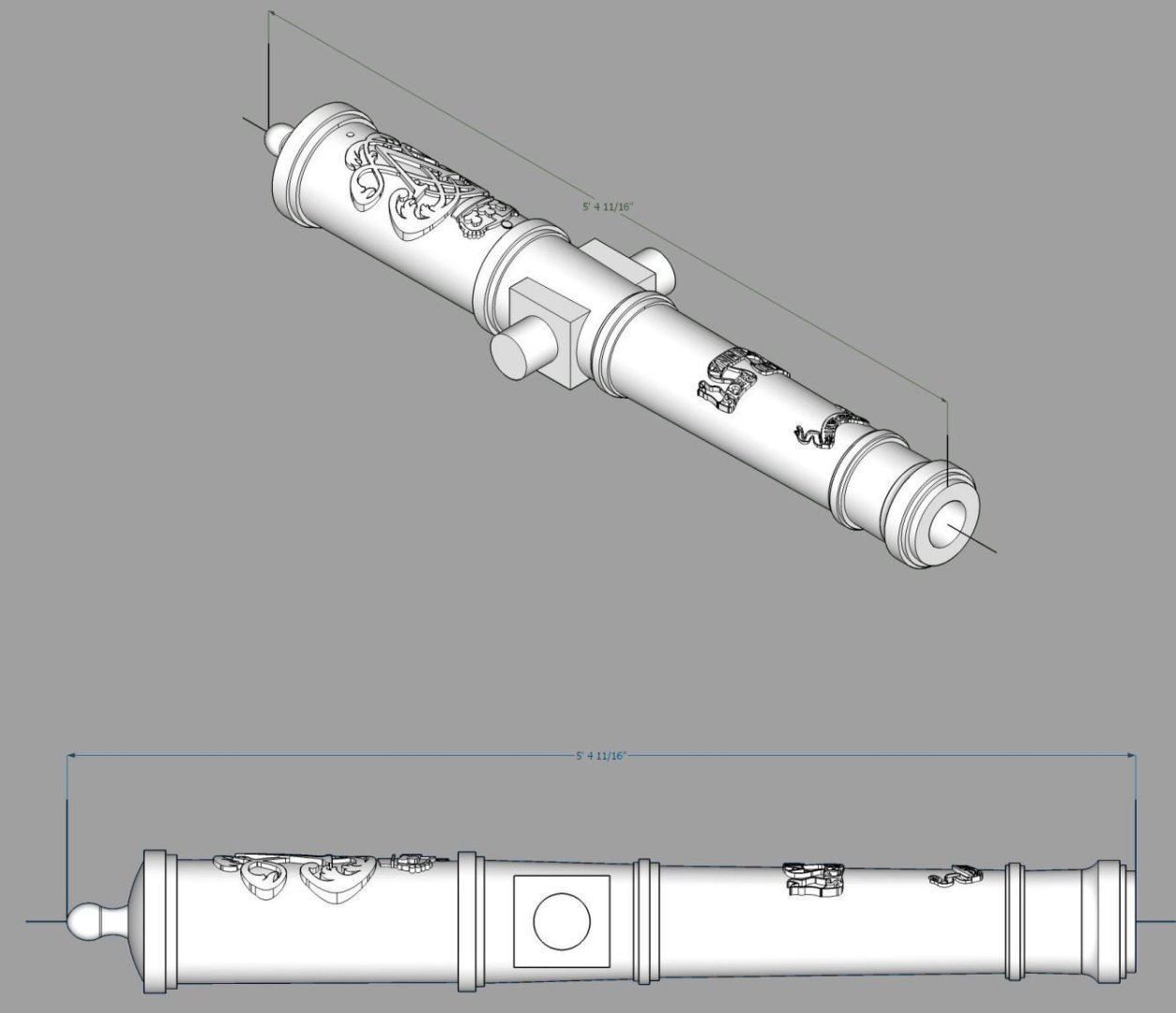
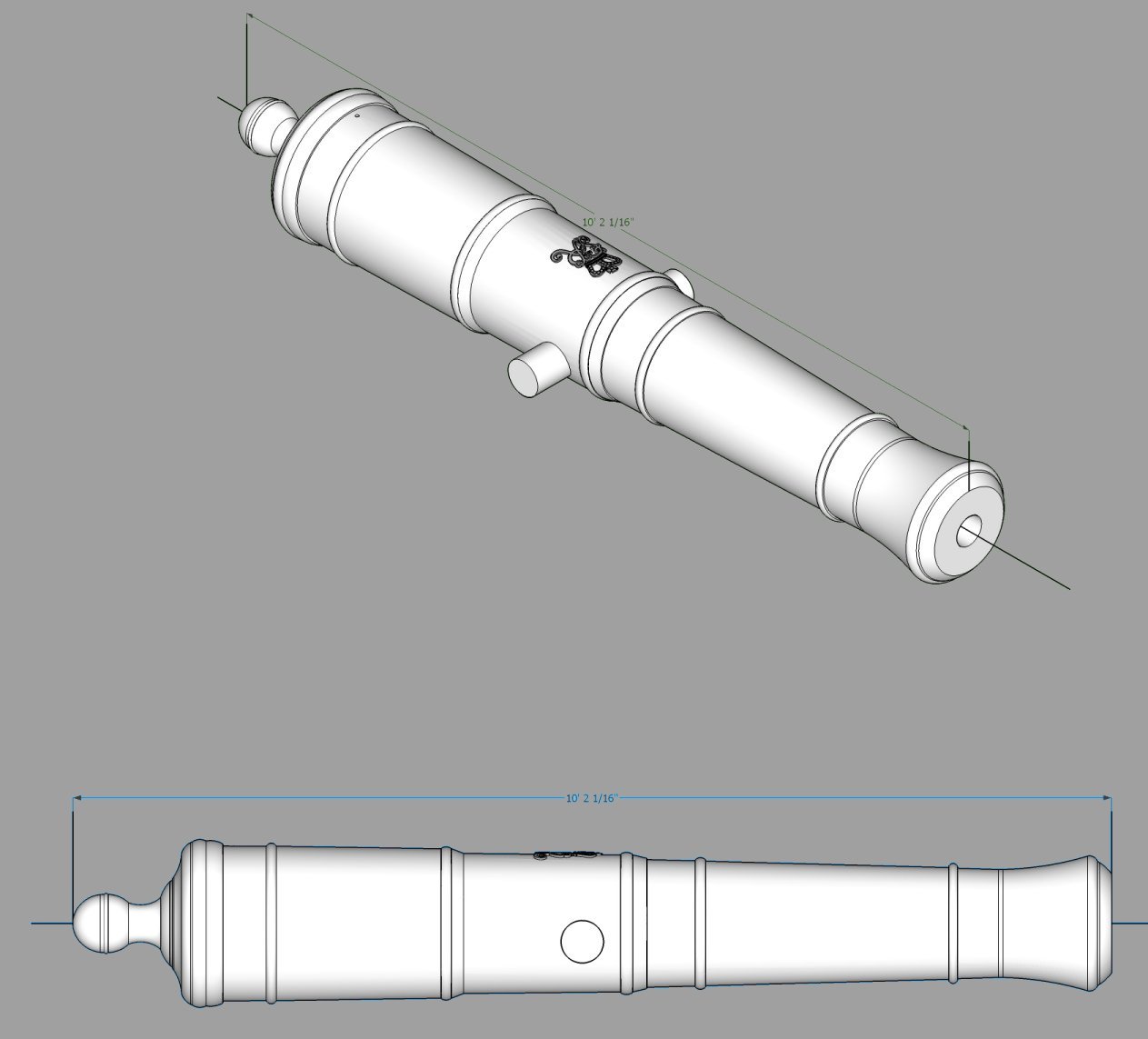
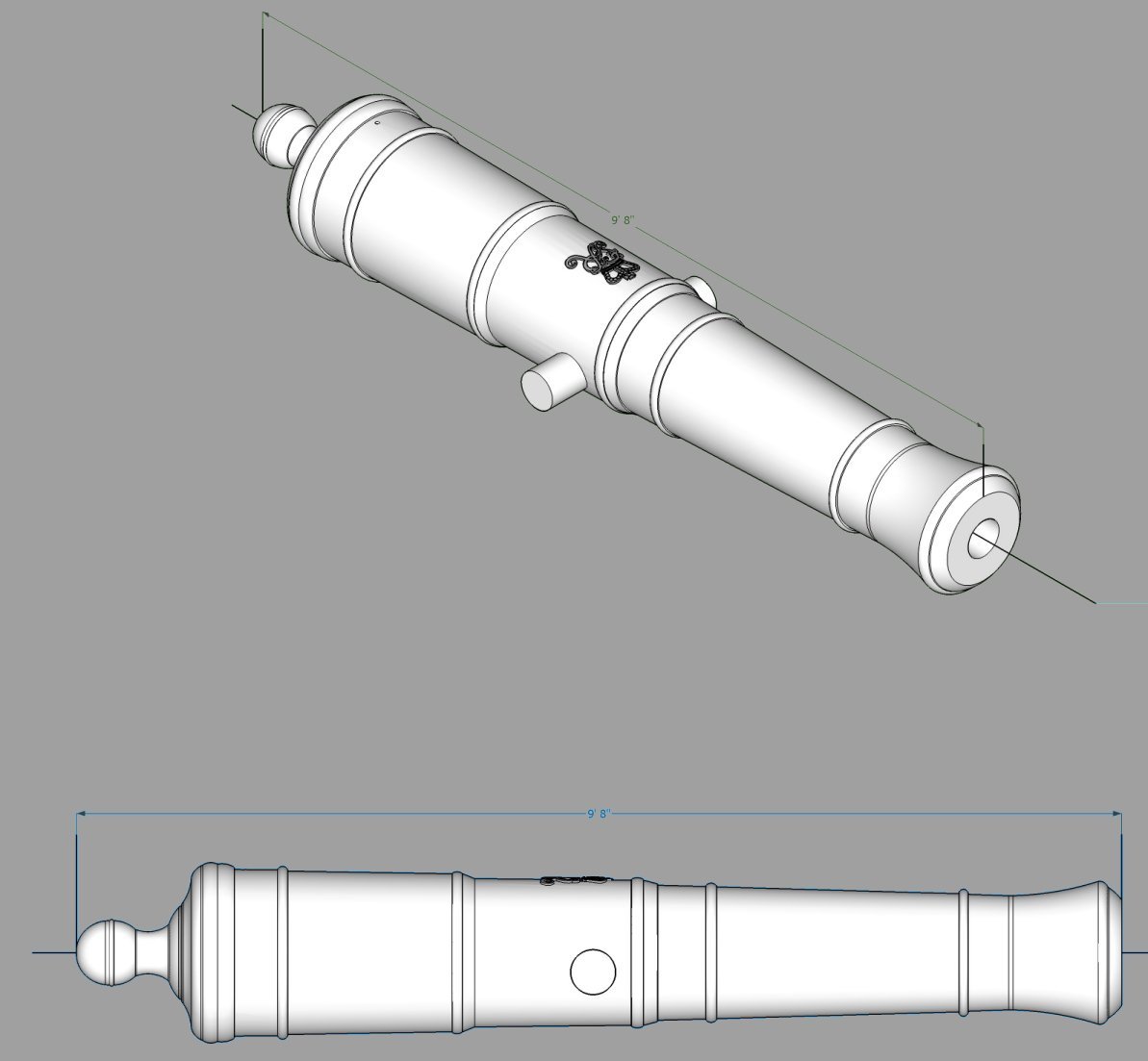
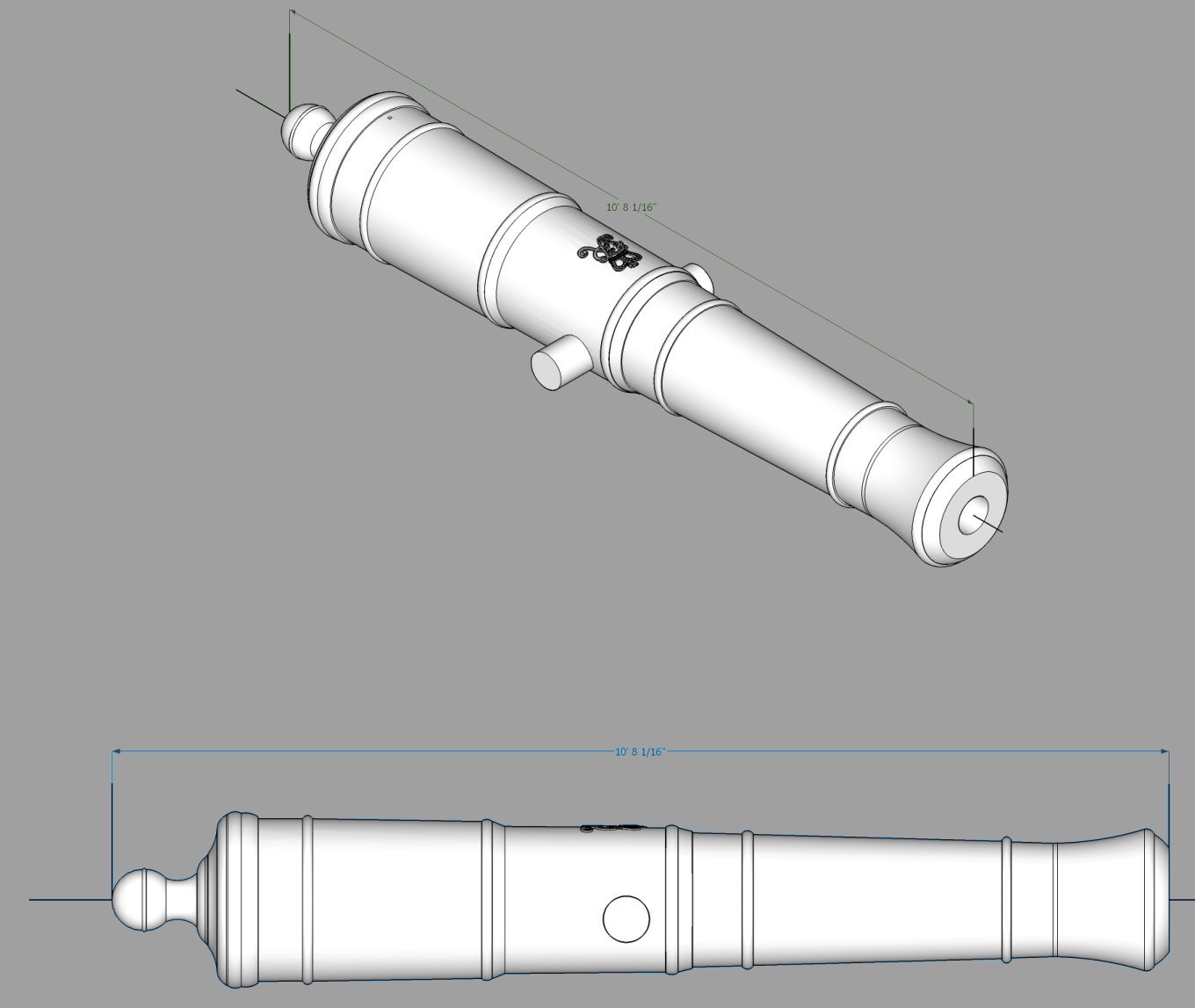
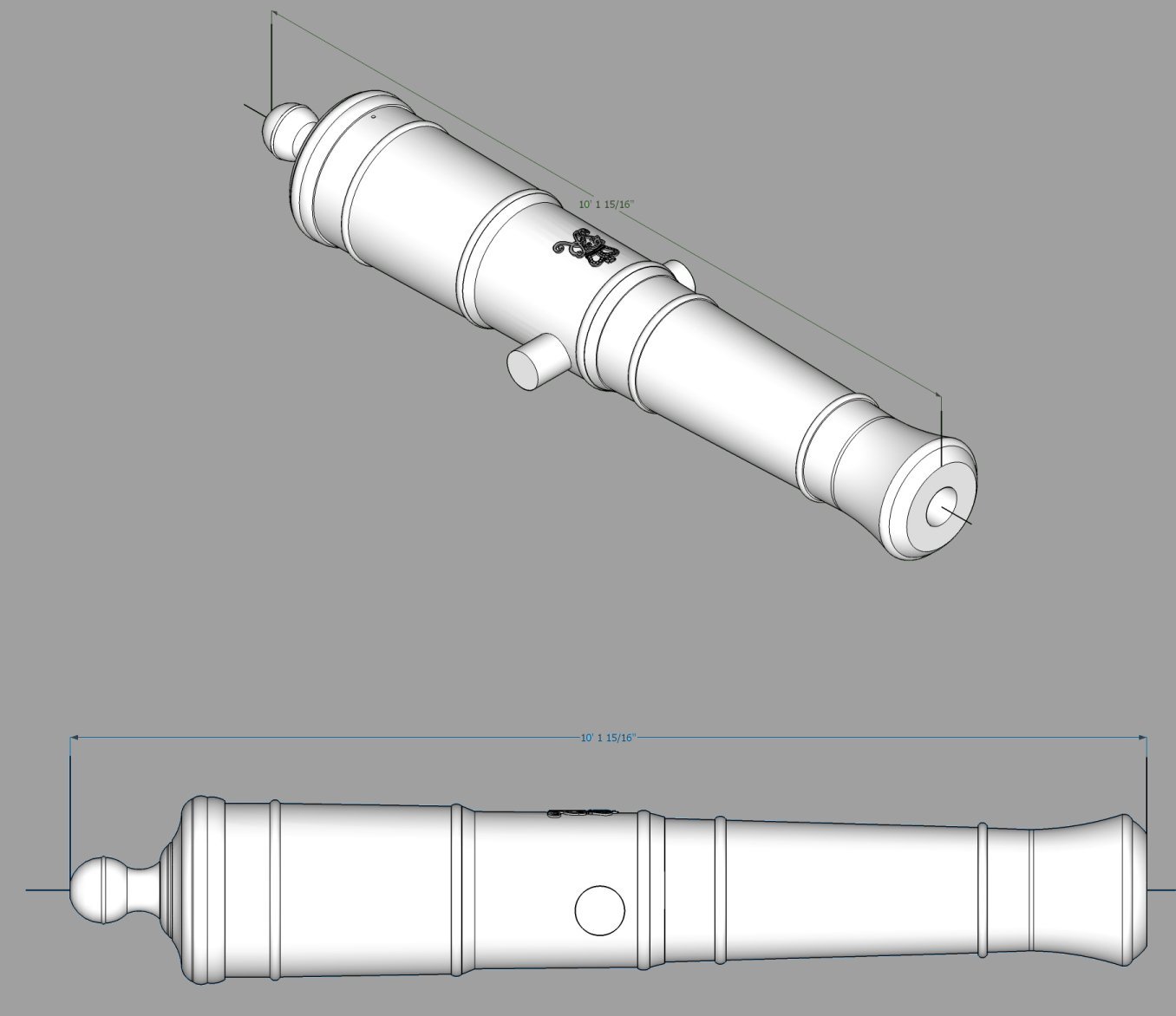
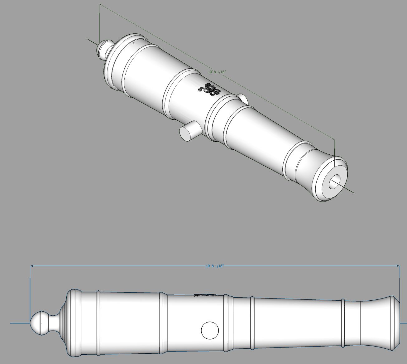
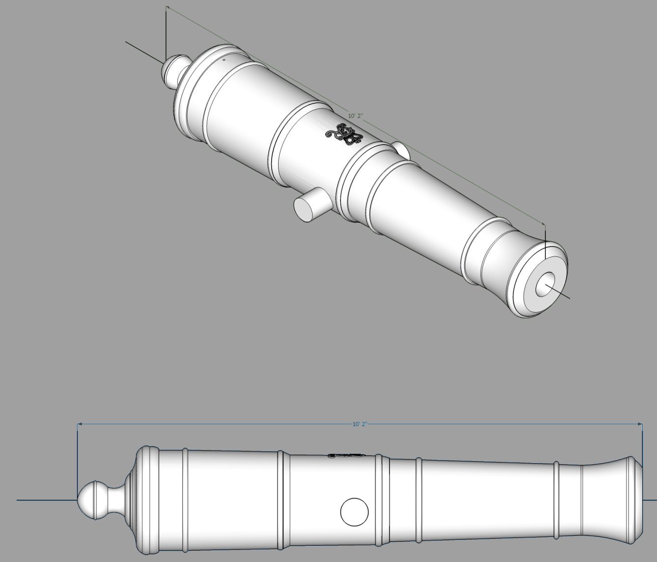
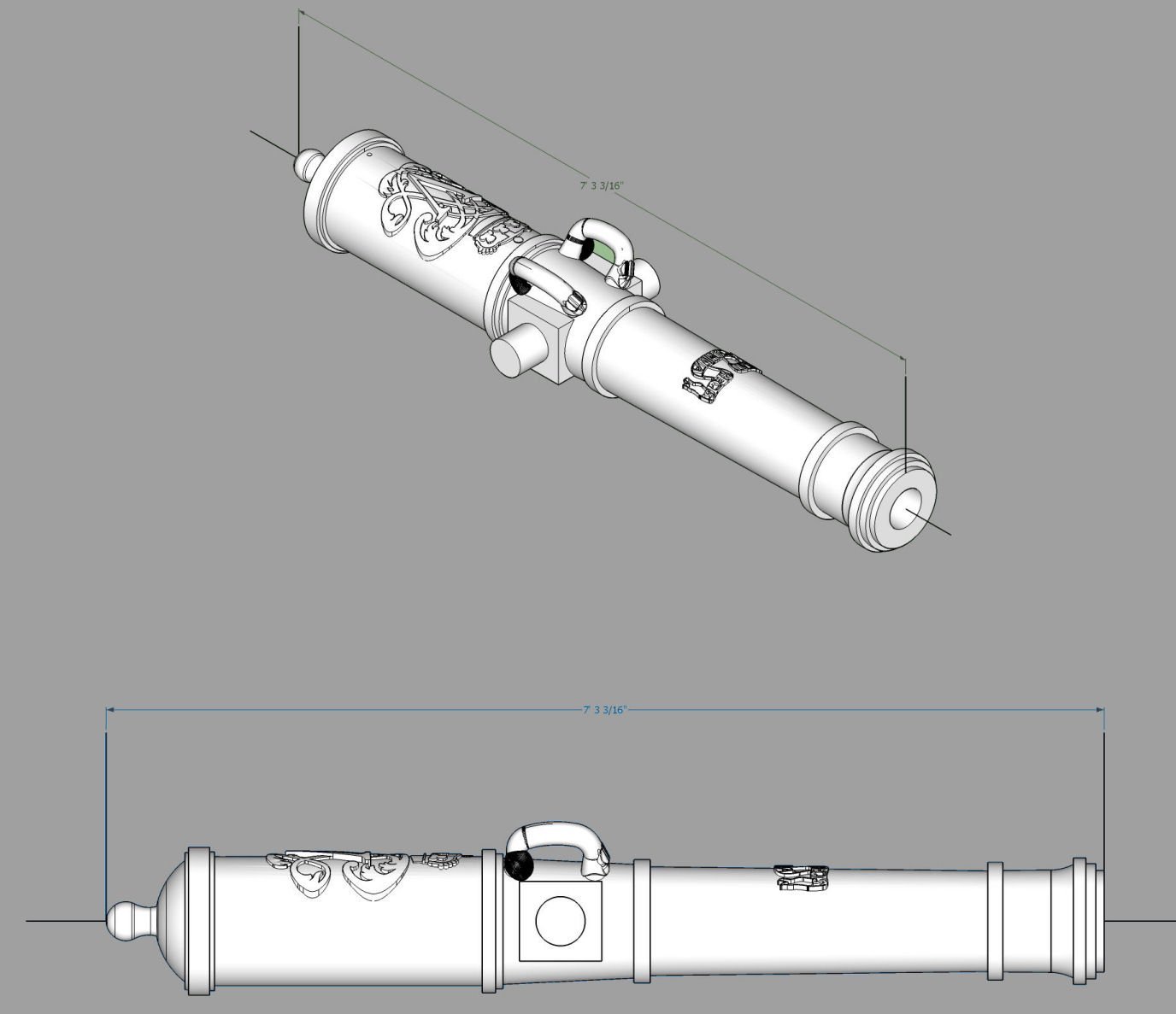
Here is a graphic of the drawing I was given for the Armstrong Pattern Cannons, with barrel and overall lengths. They closely match the data I have for the Fredrick Pattern Cannons, which were basically the Armstrongs with flash pans added. This is the best resolution I can post with the 1600X1200 pixel standard of the forum.
If you have good drawings for other sizes of Armstong, I will consider drawing them. The drawing I have for the Fredricks is similar, with a few changes in the number of each size cannons. The data I have for the Fredricks, is just that data, the drawings are too pixelated to use. I will have to generate new drawings from the Fredrick Standards, and that will take time. If all the Armstrong and Fredrick cannons were produced in the same sizes, and you have data to show this, I can eventually produce all those sizes. It has not been a trivial task to CAD the Brown, Armstrong, Fredrick, Blomefield, and 1718 Spanish cannons, please cut me some slack.

- scrubbyj427, Morgan, RossR and 5 others
-
 8
8
-
Armstrong Pattern 18 Pounder Long Full Size_3099_59mm.stl
Armstrong Pattern 18 Pounder Short Full Size_2946_93mm.stl
Armstrong Pattern 24 Pounder Long Full Size_3252_13mm.stl
Armstrong Pattern 24 Pounder Short Full Size_3096_55mm.stl
Armstrong Pattern 32 Pounder Long Full Size_3252_13mm.stl
Armstrong Pattern 32 Pounder Short Full Size_3098_80mm.stl
- Lieste and scrubbyj427
-
 2
2
-
STL Files for the Armstrong cannons.
Armstrong Pattern 6 Pounder Long Full Size_2742_01mm.stl
Armstrong Pattern 6 Pounder Short Full Size_2436_81mm.stl
Armstrong Pattern 9 Pounder Long 114 Inch Full Size_2893_22mm.stl
Armstrong Pattern 9 Pounder Long 120 Inch Full Size_3045_75mm.stl
Armstrong Pattern 9 Pounder Short 102 Inch Full Size_2589_08mm.stl
Armstrong Pattern 9 Pounder Short 108 Inch Full Size_2741_08mm.stl
Armstrong Pattern 12 Pounder Long Full Size_3060_30mm.stl
Armstrong Pattern 12 Pounder Medium Full Size_2907_77mm.stl
Armstrong Pattern 12 Pounder Short Full Size_2755_37mm.stl
- Lieste and scrubbyj427
-
2
-
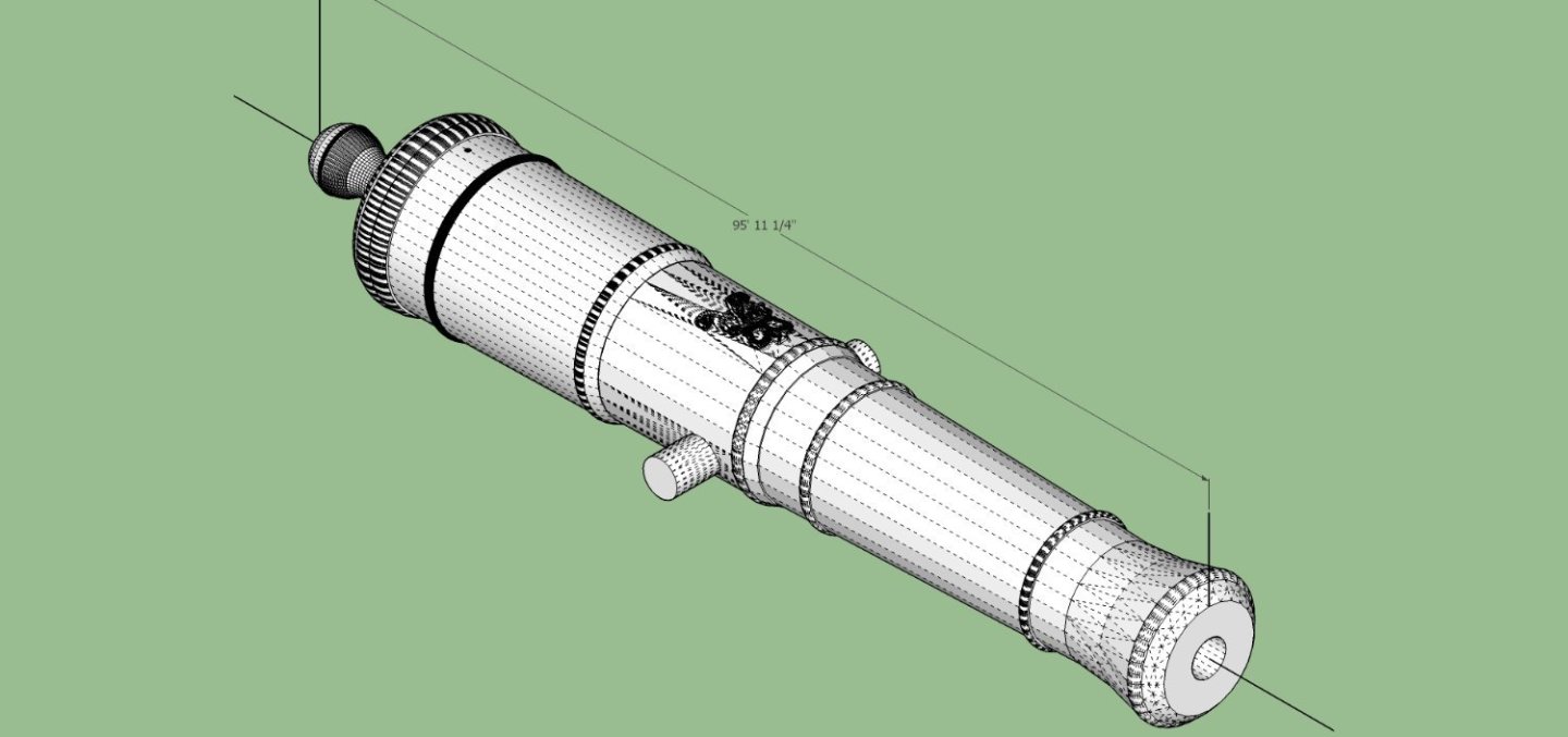
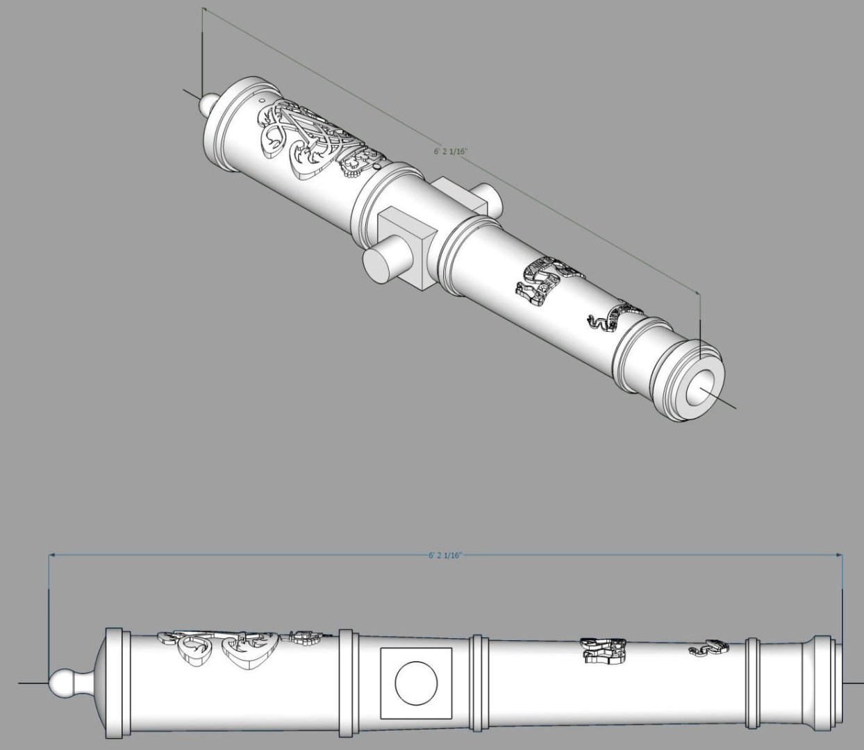
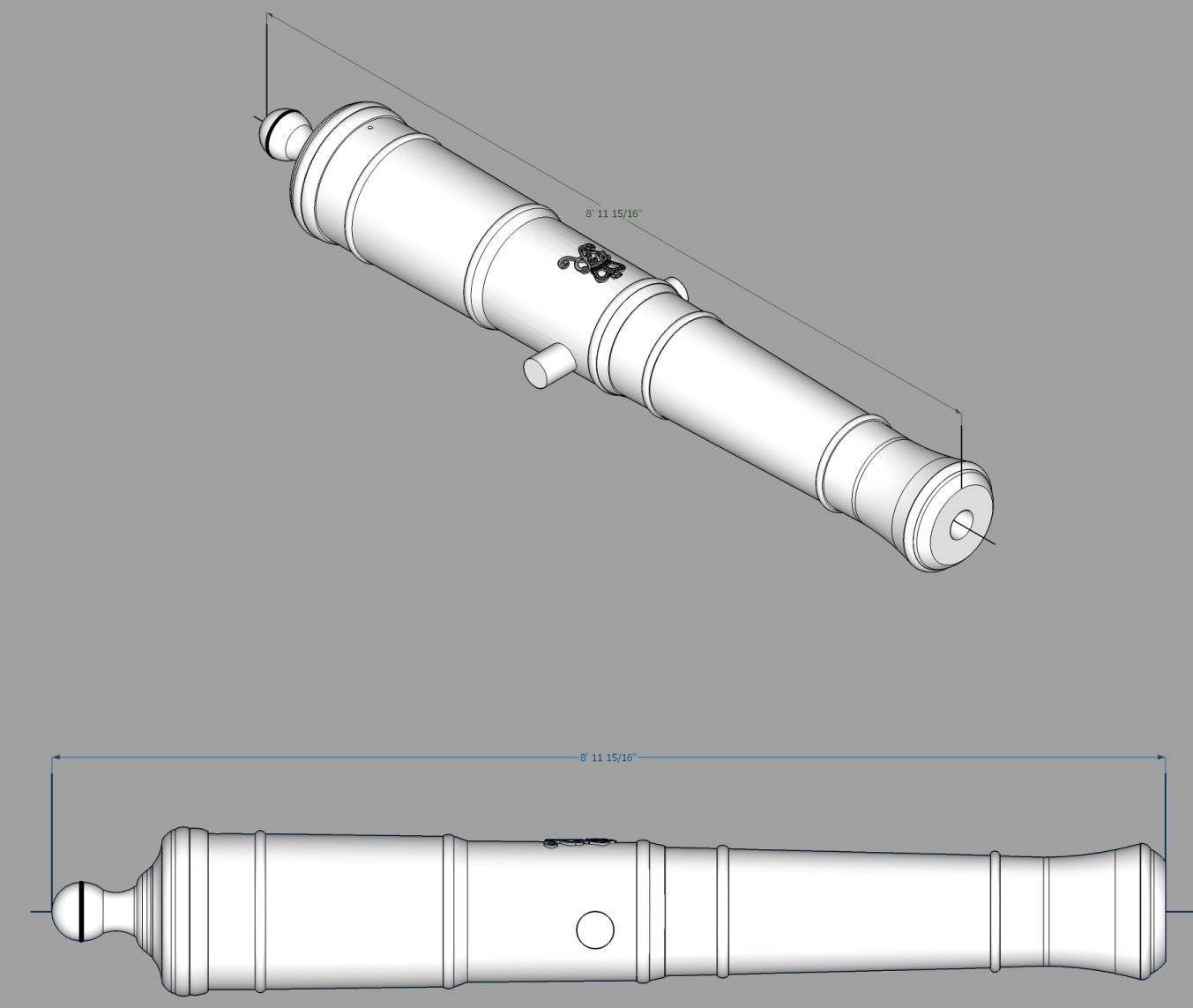
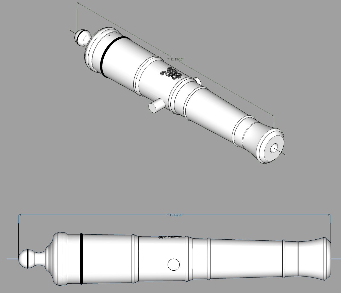
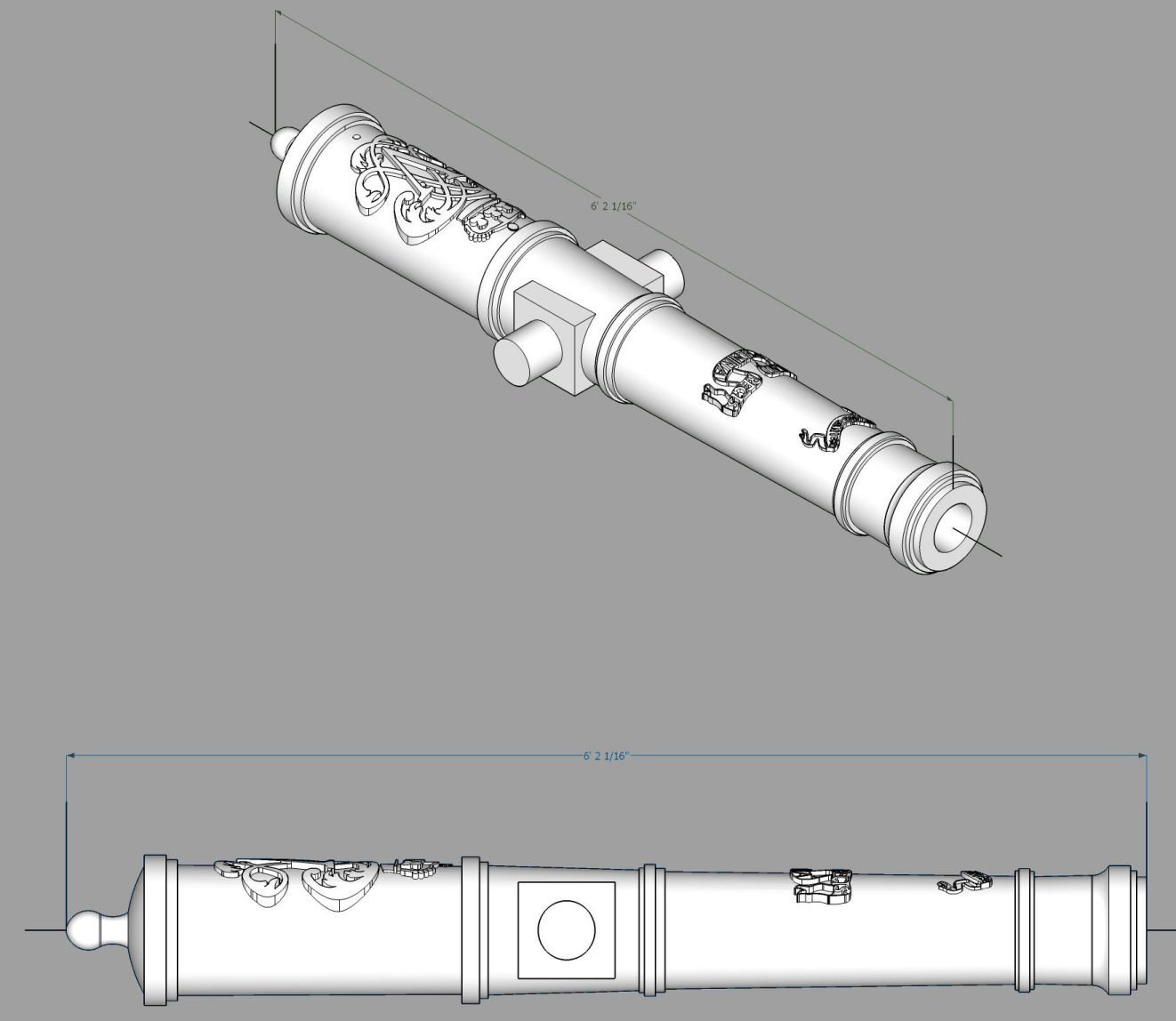
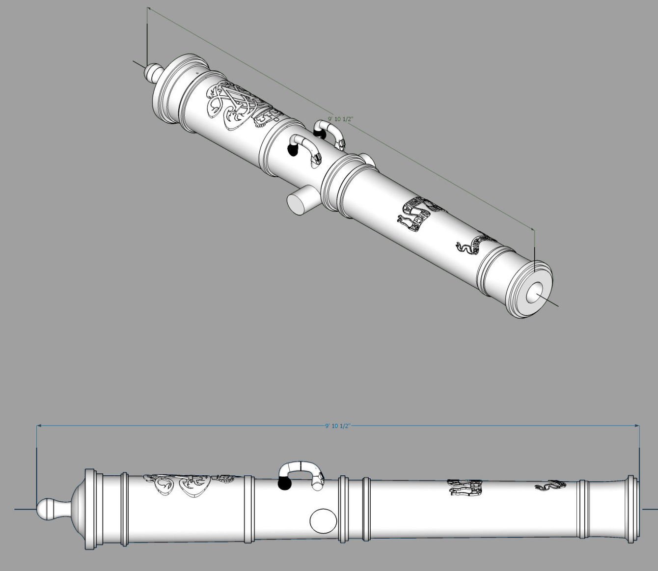
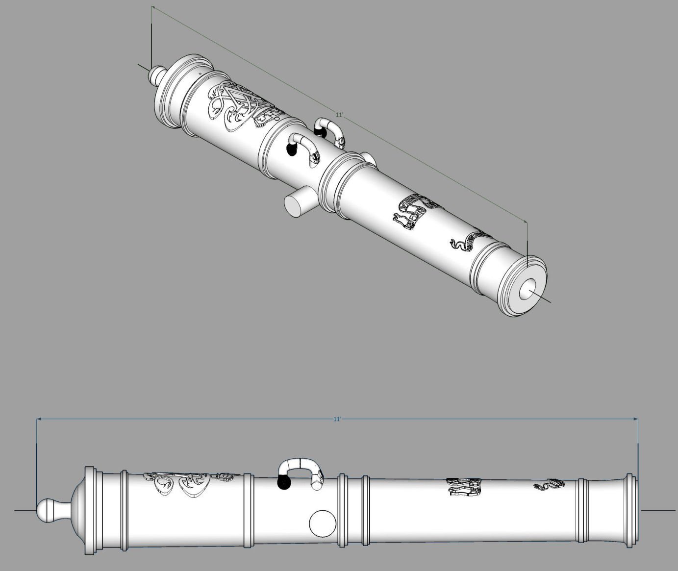
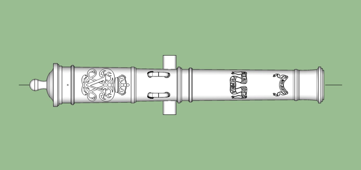
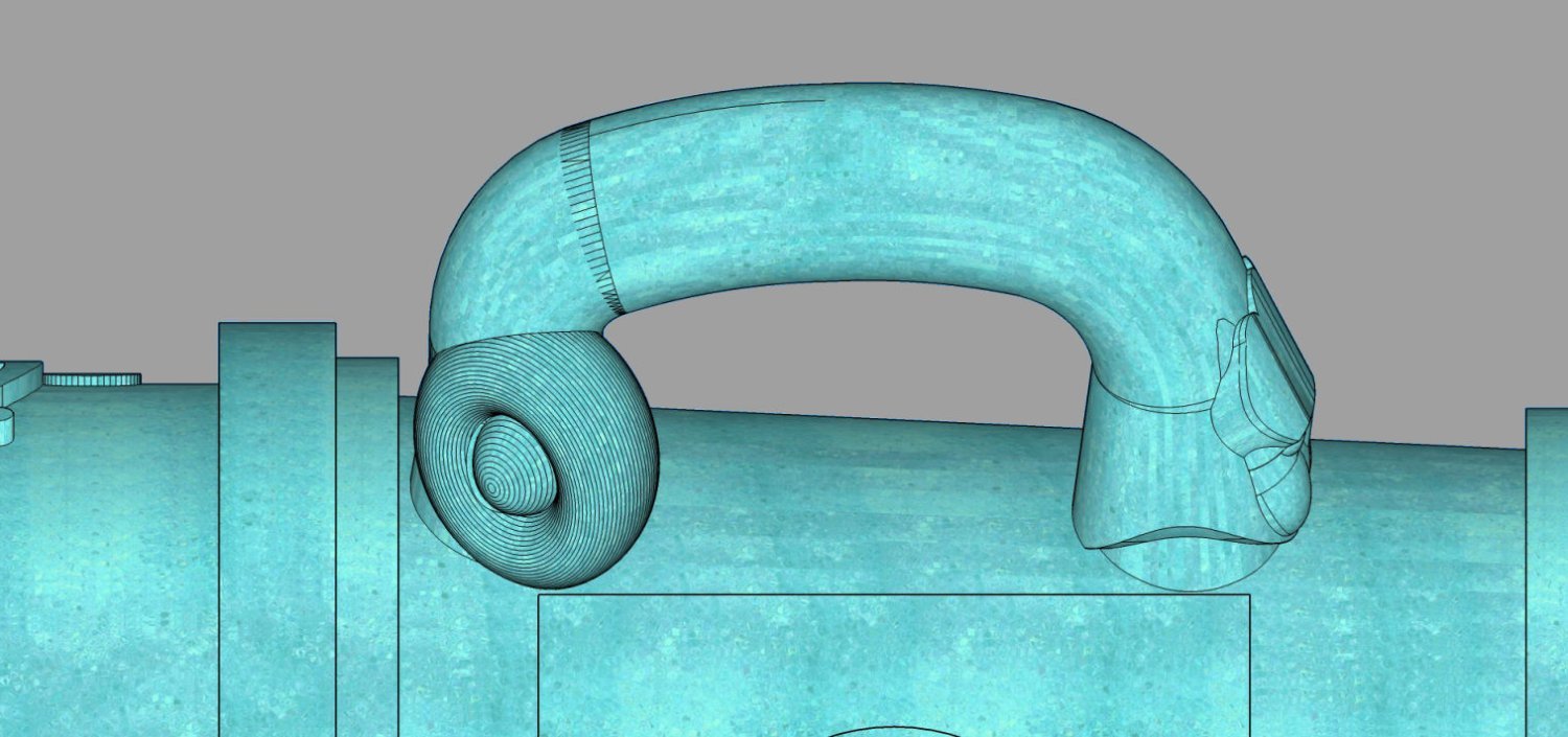
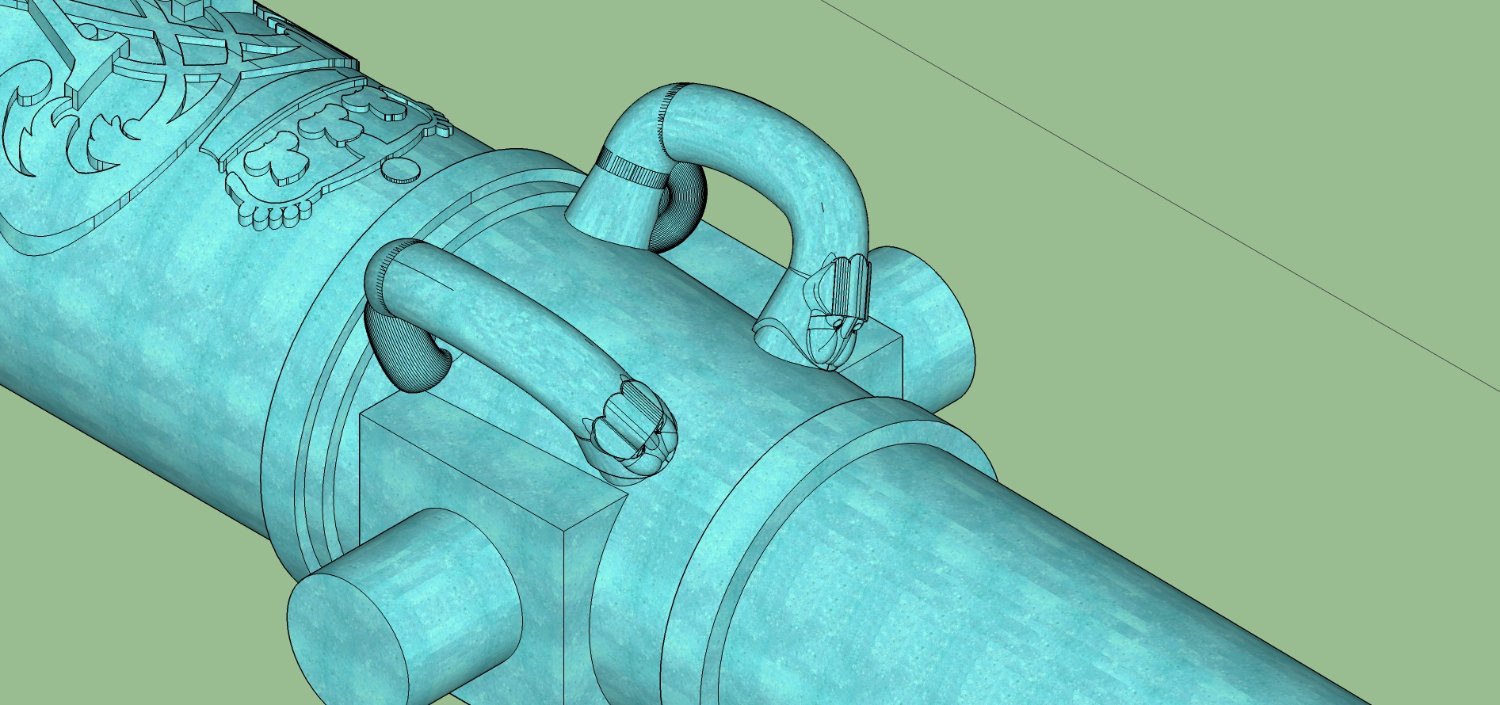
Finished redrawing the Armstrong Pattern 1725 to 1759 cannons. As I received the 3D drawings, they had a lest detailed barrel. The drawings were made up of cylinders of 24 facets for a full circle. This made obvious flats on the print, when printed at the larger scales. In the graphic below, you can see the cruder faceted barrel on the right, with 24 facets per circle, and the better breach area with 48 facets. Even 24 facets, gets slightly noticeable at 1/24th scale. For later cannons I drew them at 72 facets per circle, but for these I had some limitations with reusing parts of the original drawings.
I will be posting the STL files in the next post. You are free to use them for your private use. For commercial use, please contact me. I don't plan on asking much, if anything, for commercial use.
I can also print cannons for you in scales from 1/24th to 1/100th with my resin printer. I do not think lower scales will print well on my printer.
Hopefully all my cannon files will be available in a database in the near future.
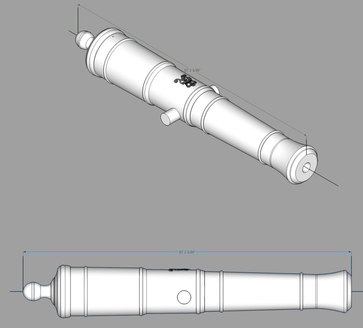
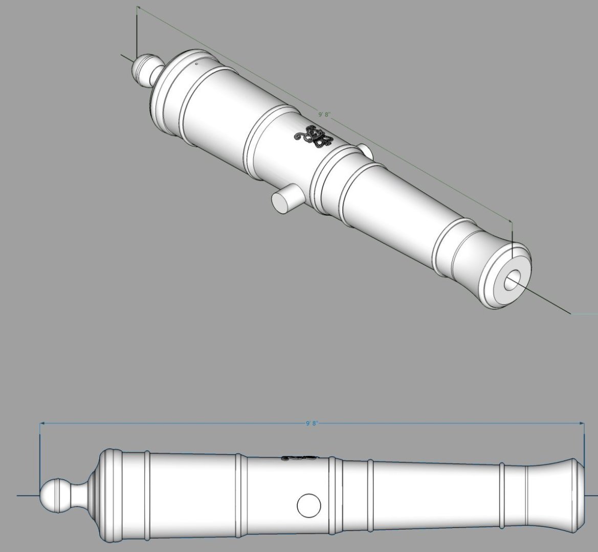
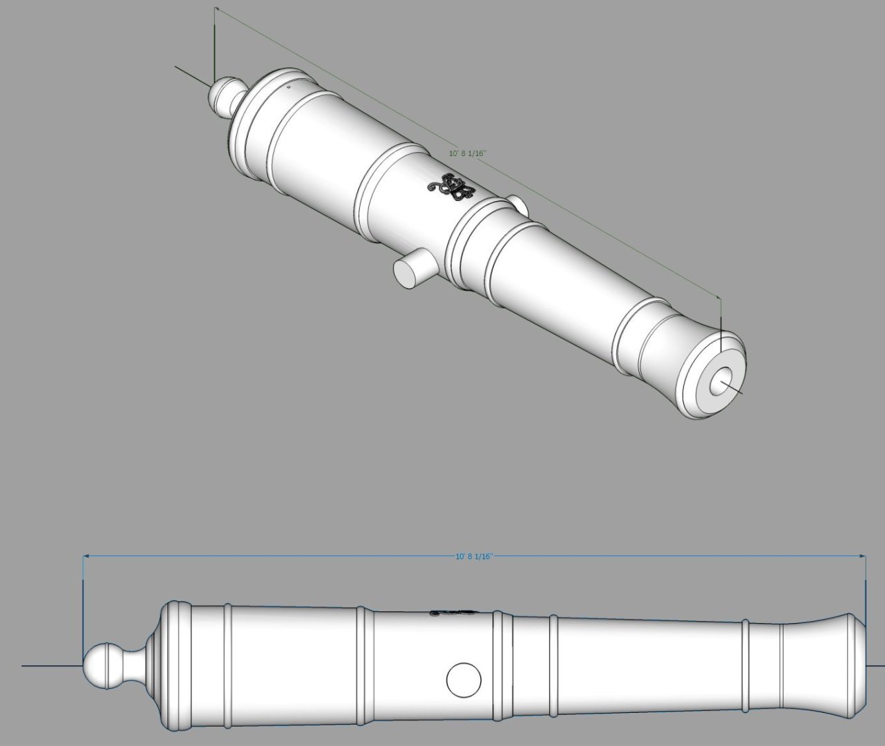
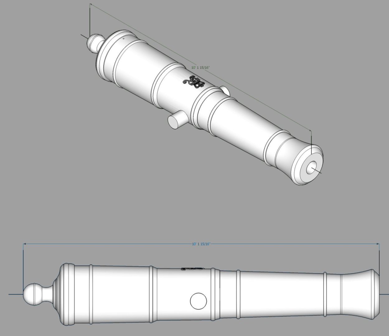
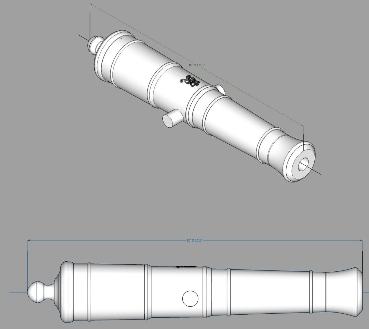
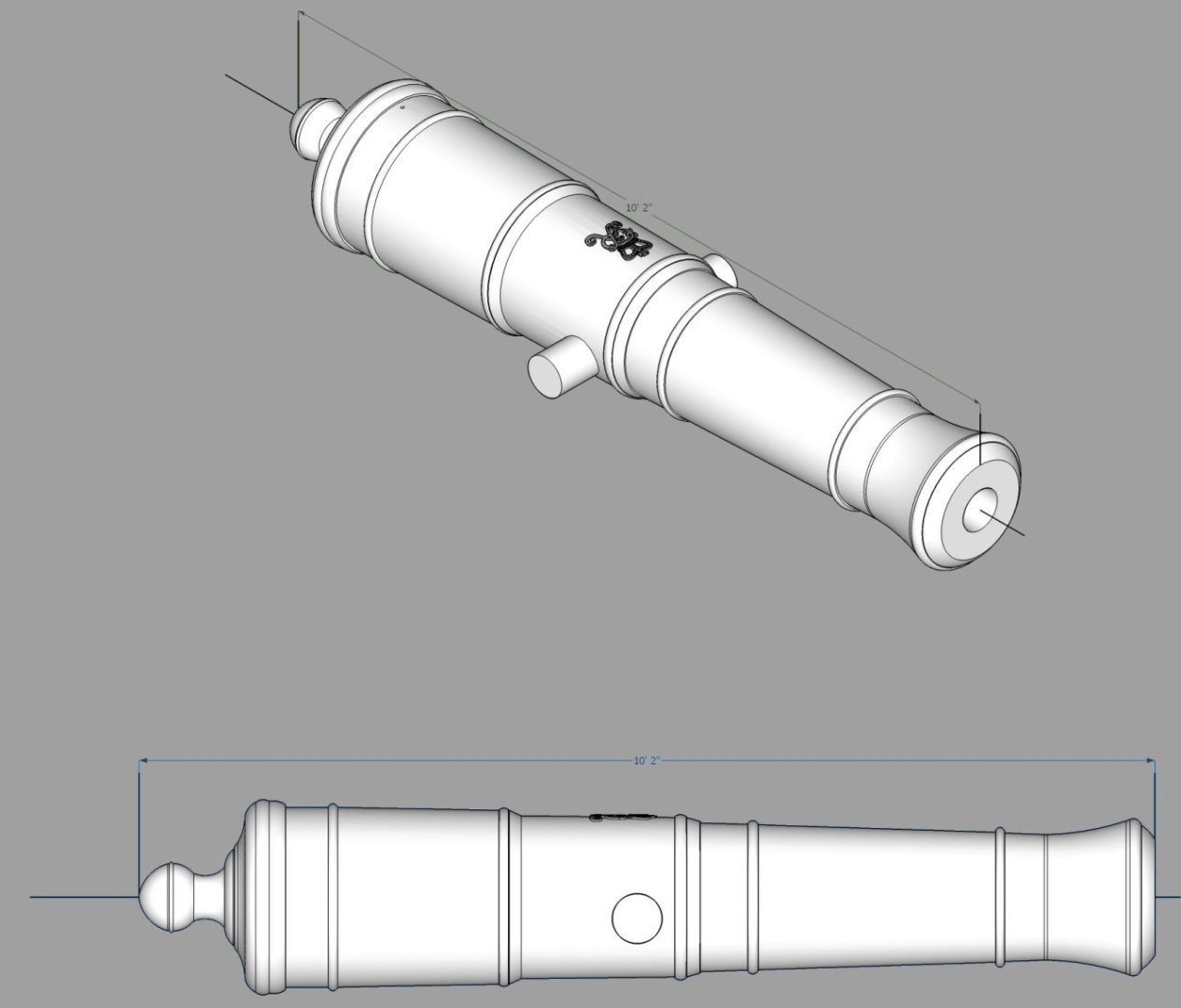
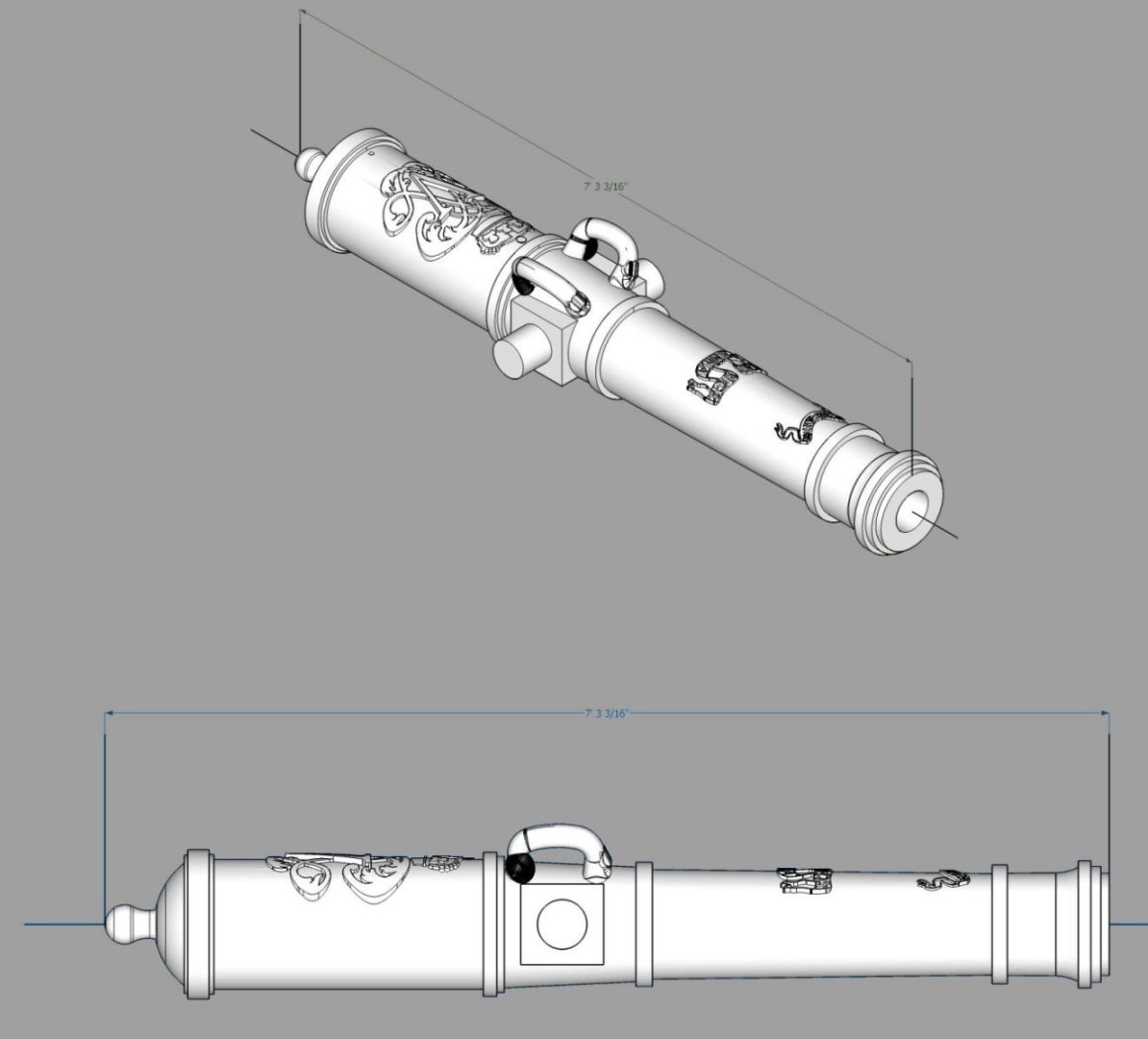
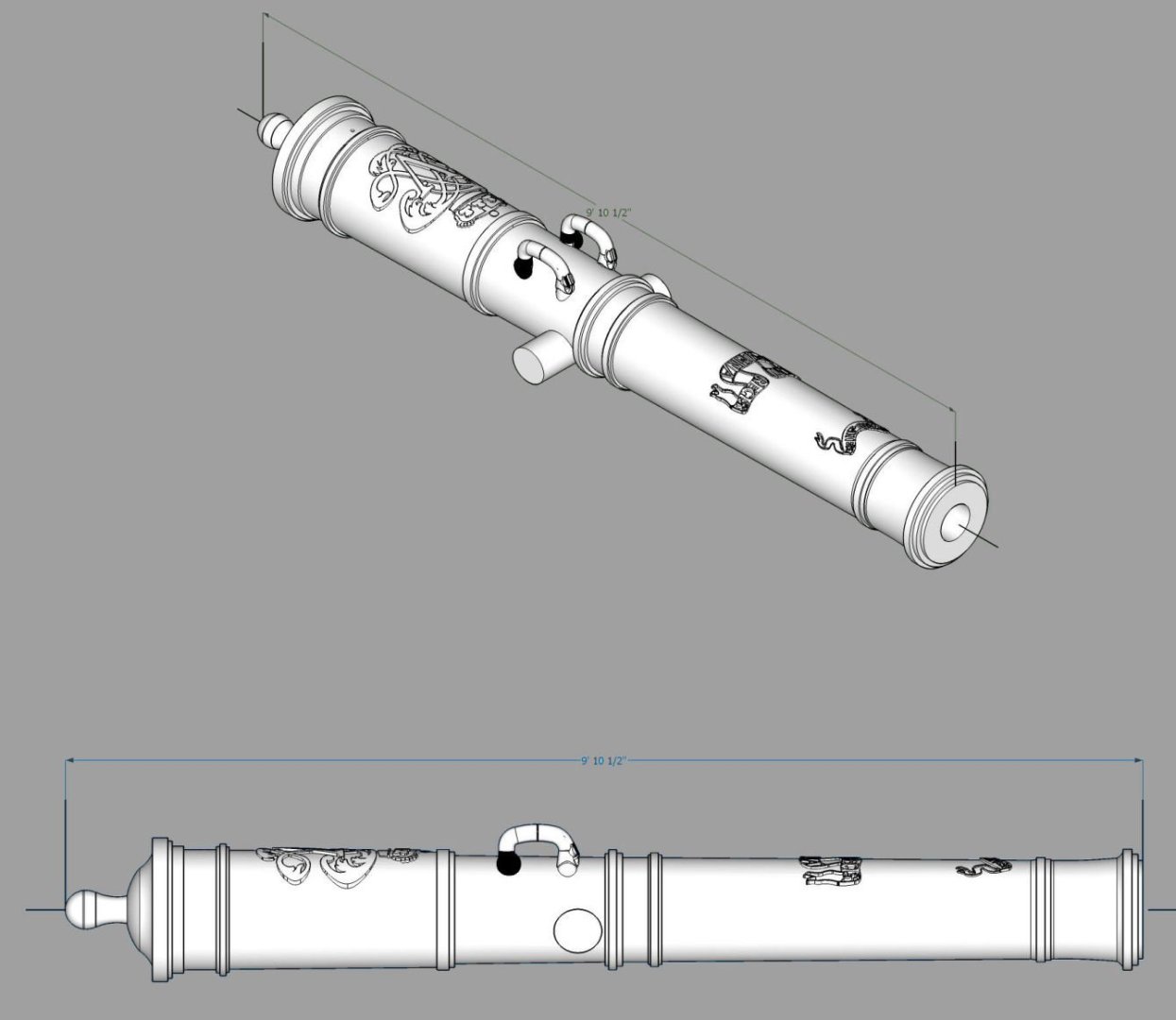
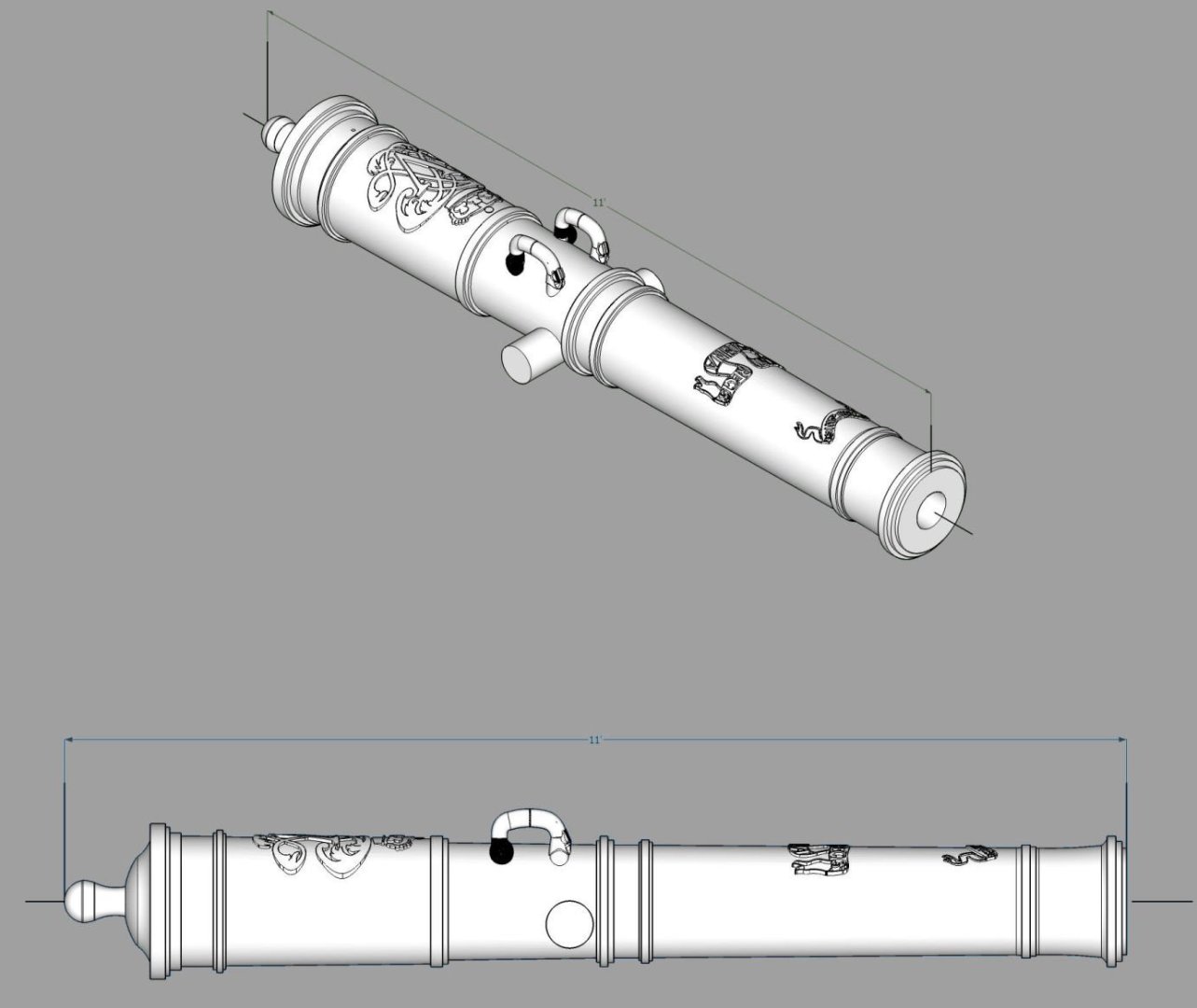
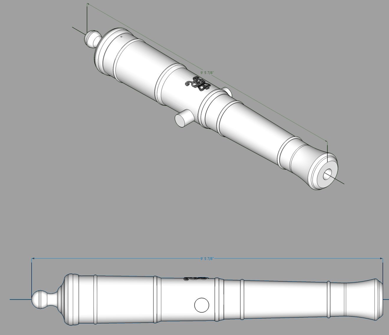
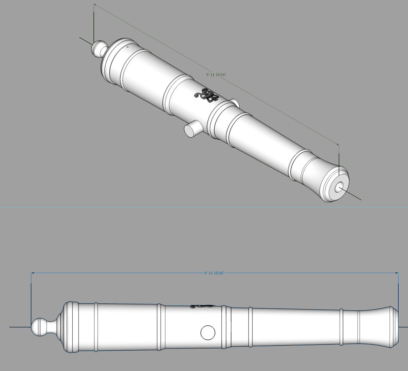
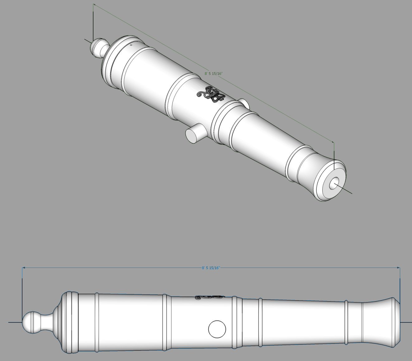
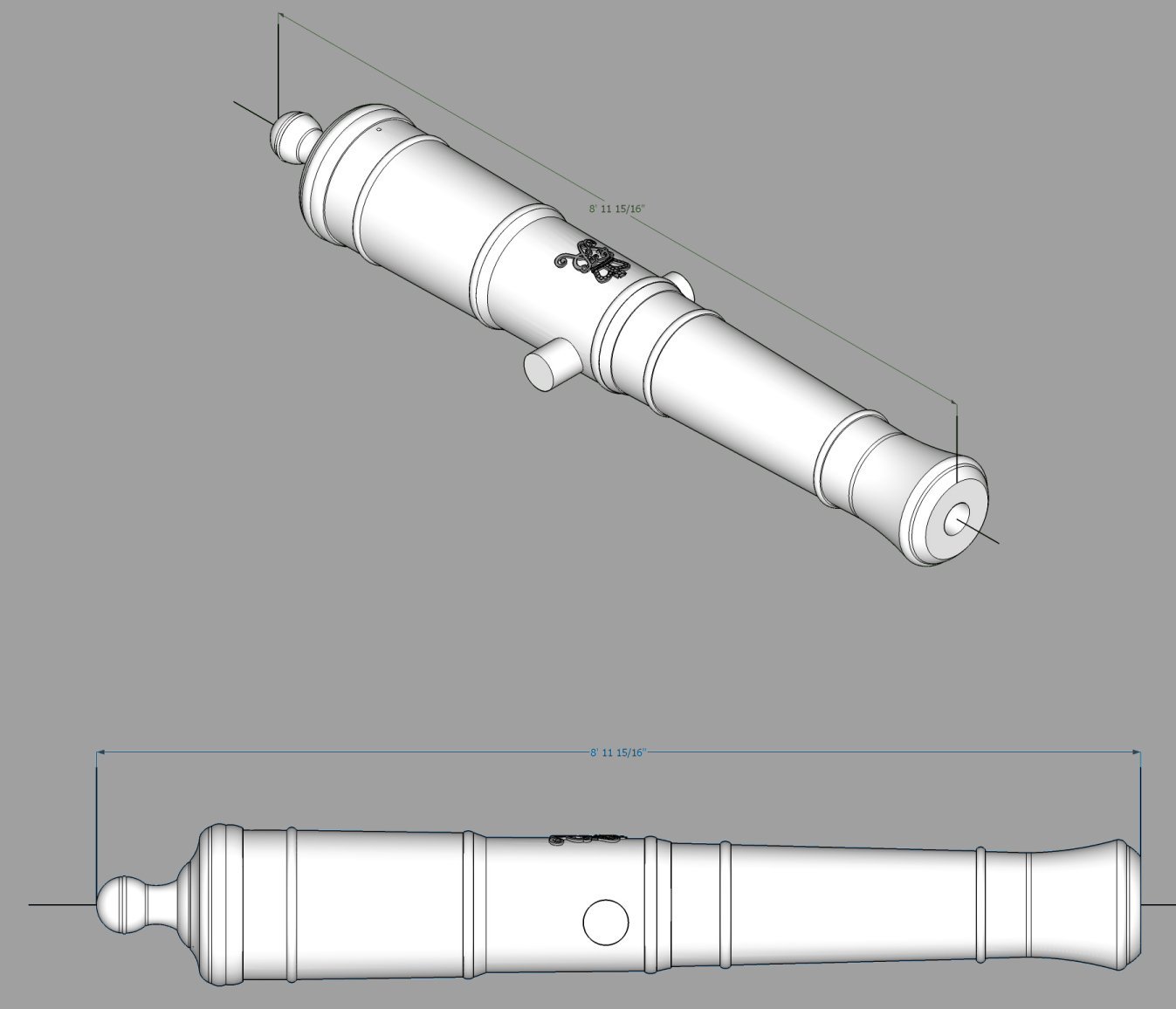
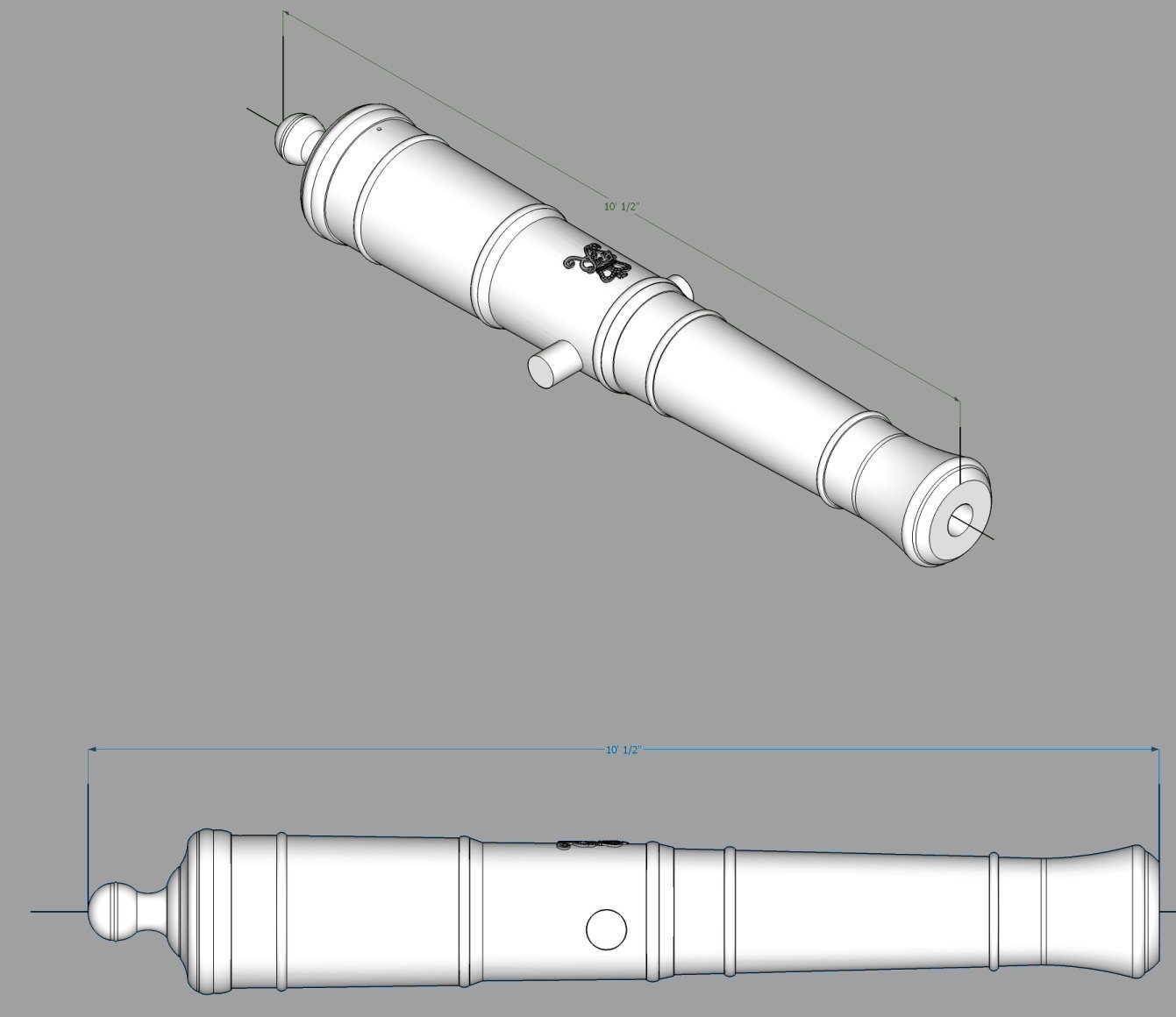
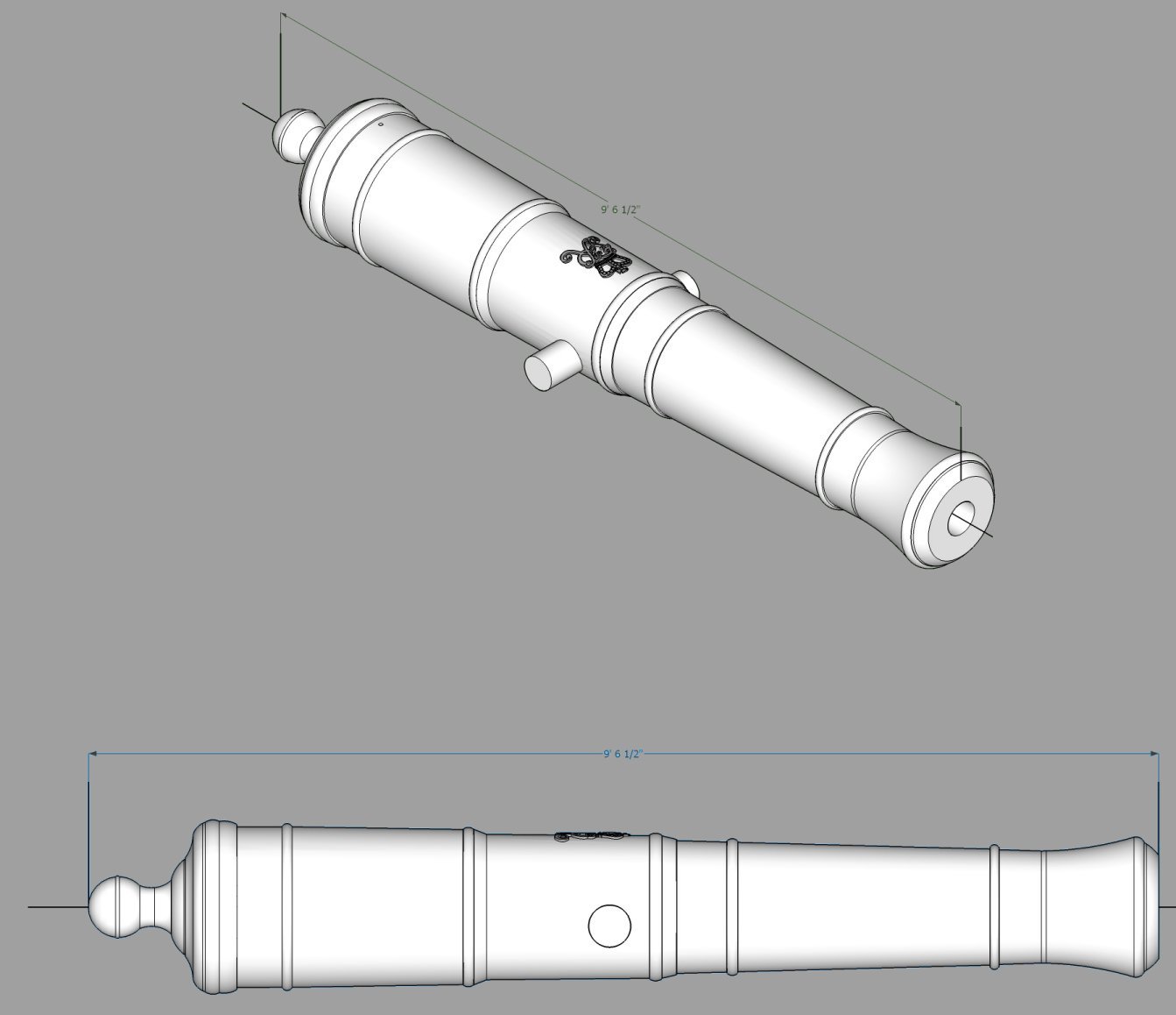
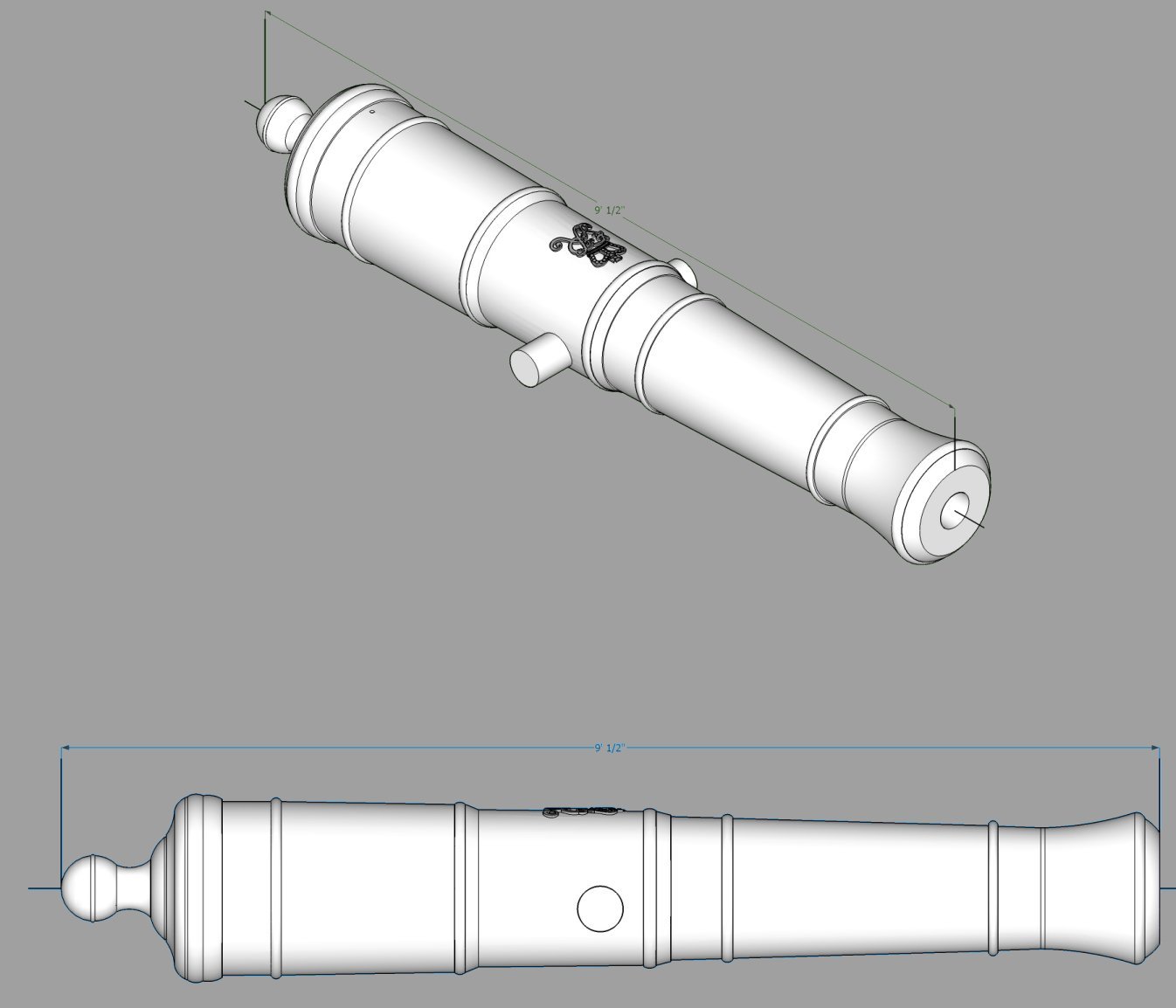
Here are the drawings of the Armstrong Cannons, for the sizes I have info for.
6 Pounders:
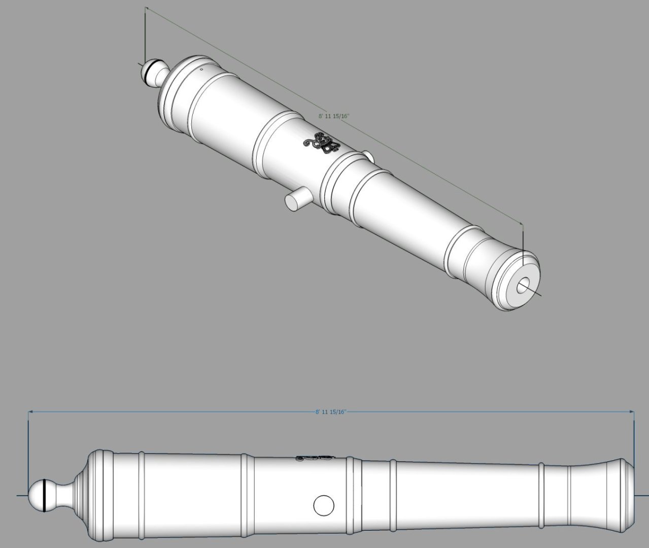
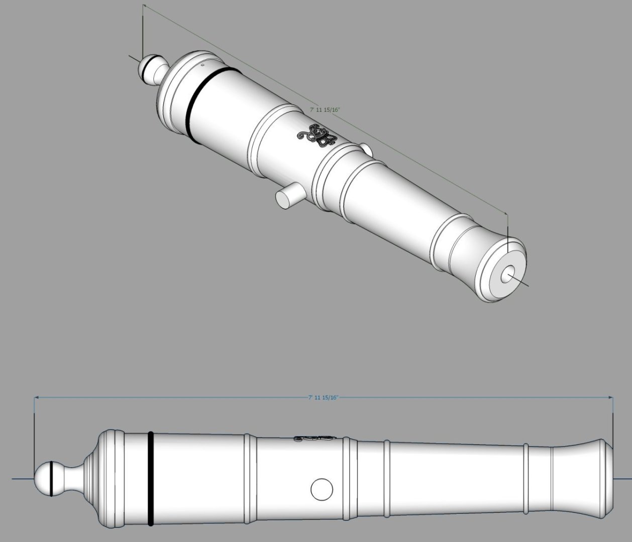
9 Pounders
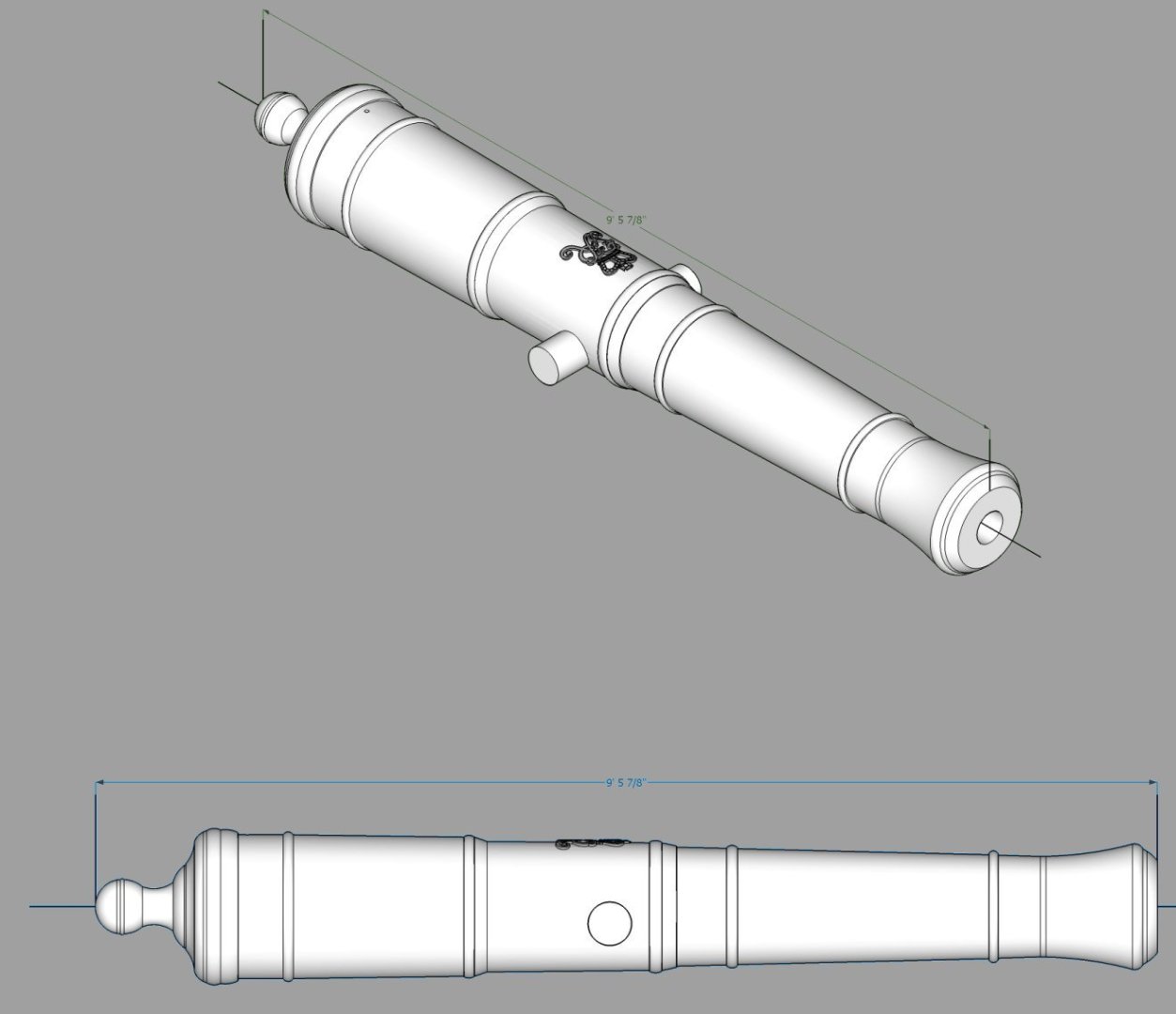
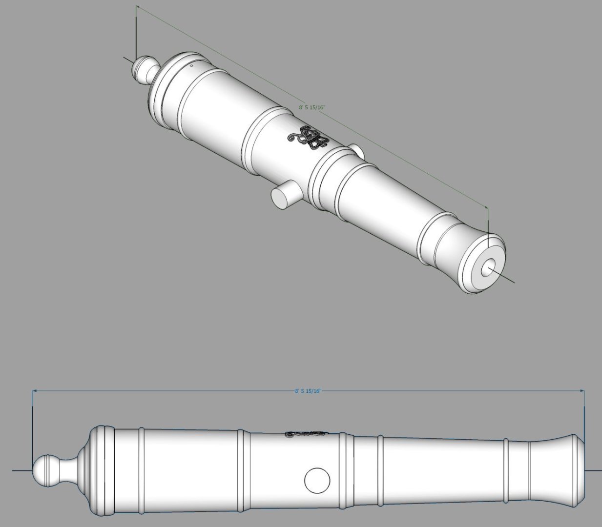
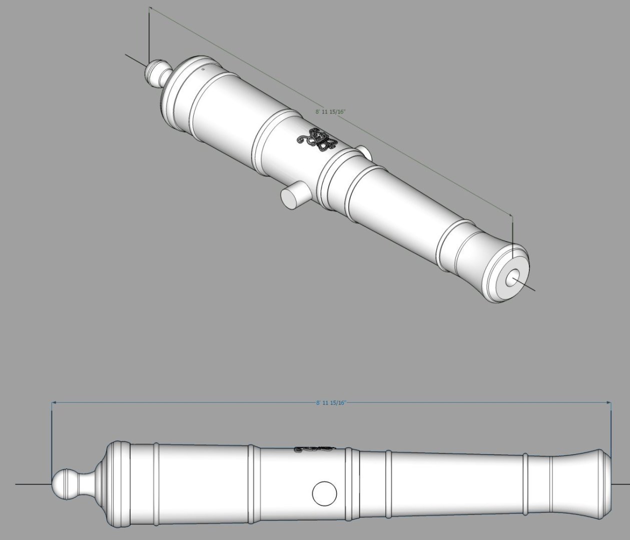
12 Pounders
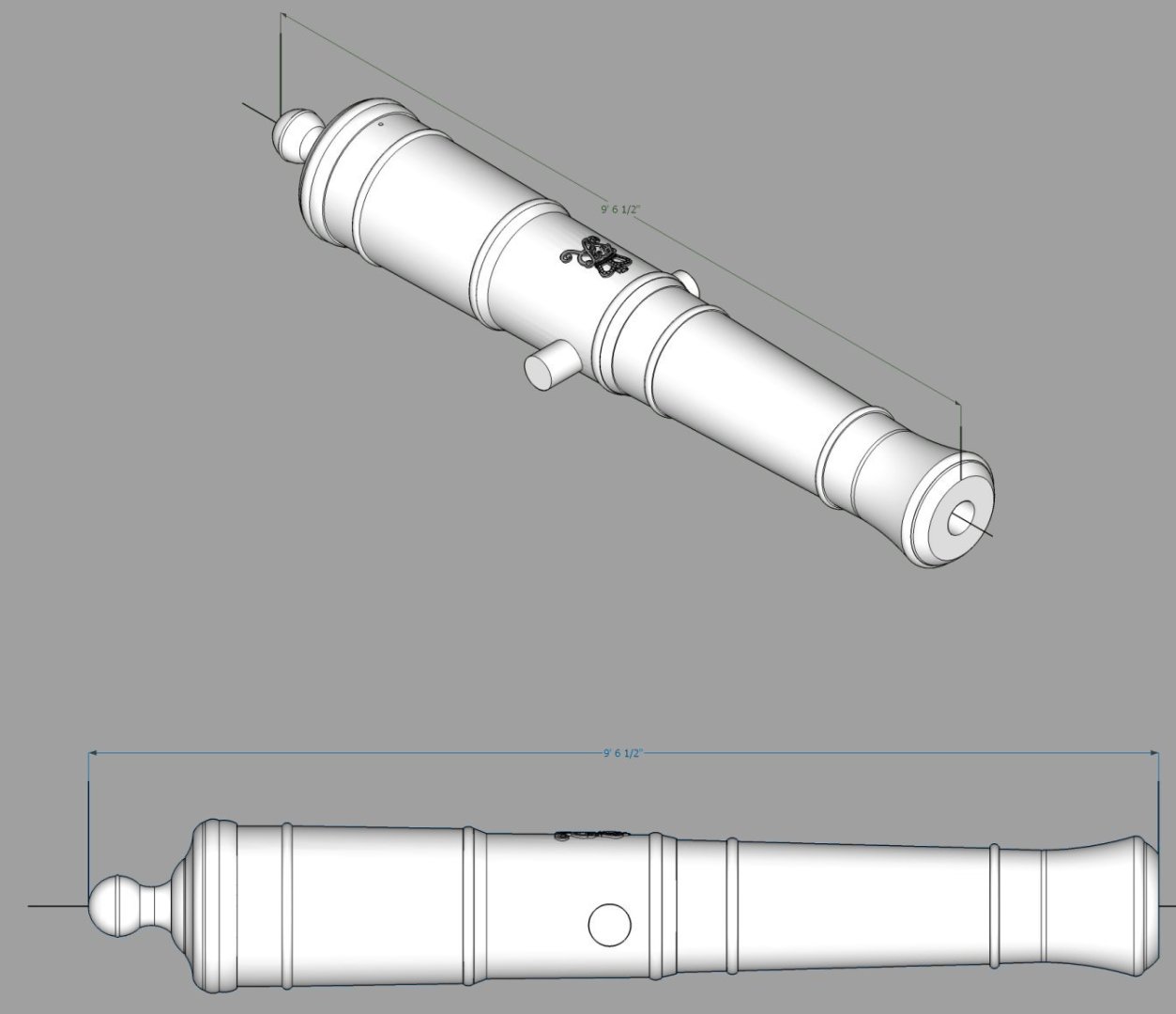
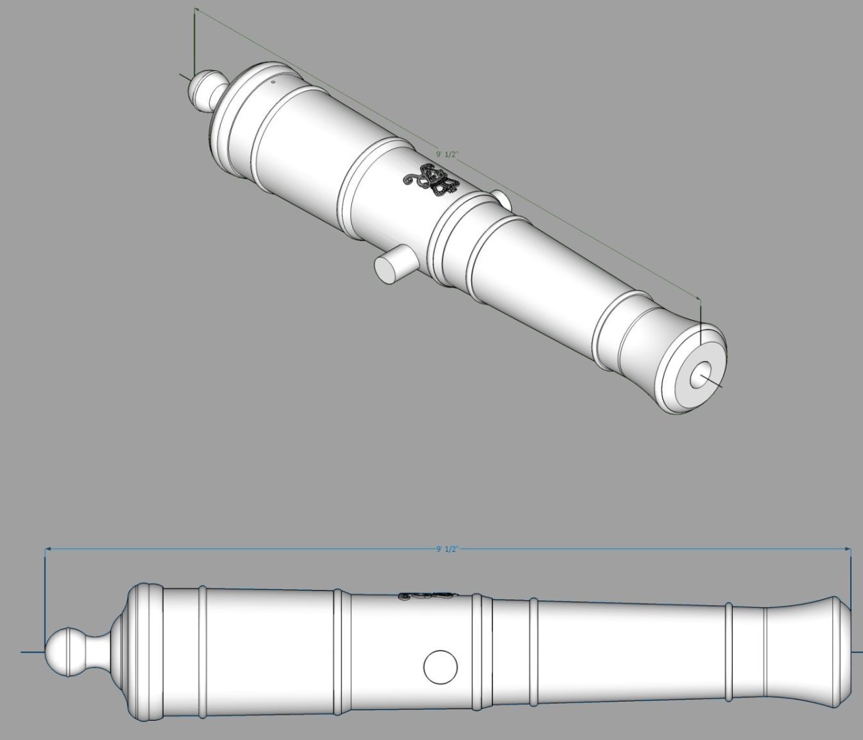
18 Pounders:
24 Pounders:
32 Pounders:
- scrubbyj427, Seventynet and Lieste
-
2
-
1
-
-
Part 04
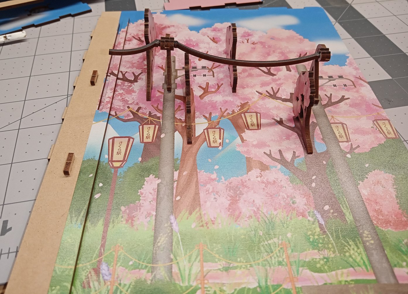
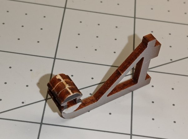
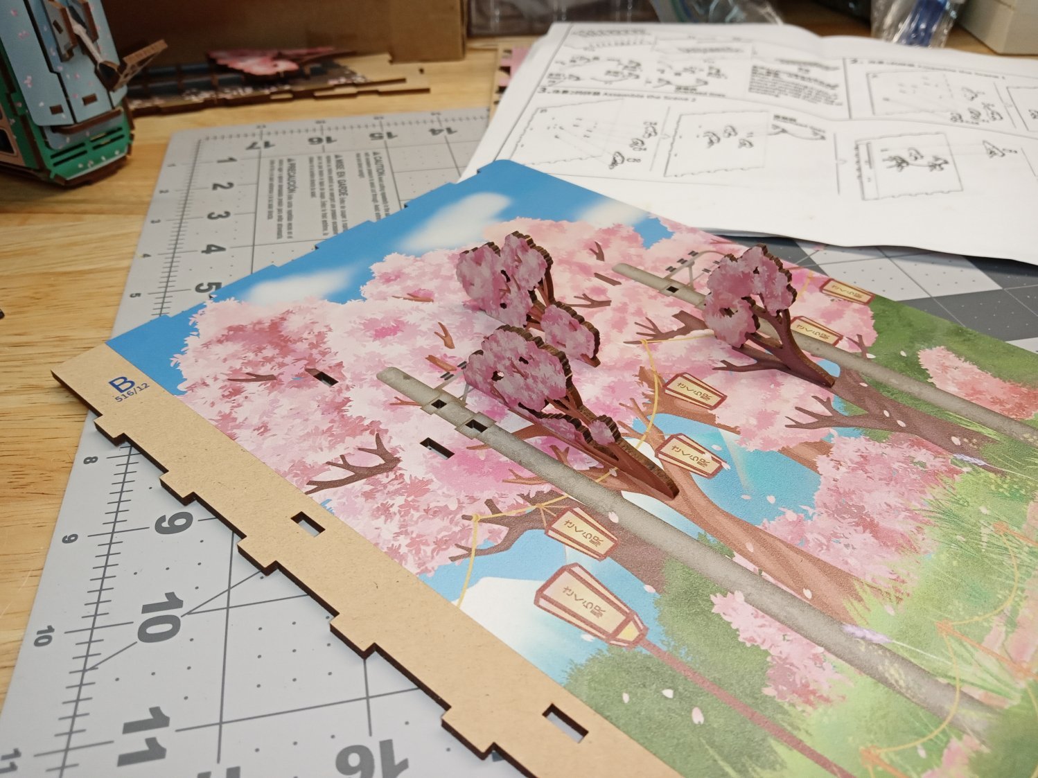
The power lines were the next thing to install, then the last cherry branch. I built them in place, so as to avoid breaking them, though I managed to break one of the supports anyway. I made the mistake of pressing on the vertical part of the hanger. A few minutes holding the joint in place while the glue set, fixed it.

The righthand support has the line attached only on one side, the other is printed with an insulator graphic. This side faces the front.
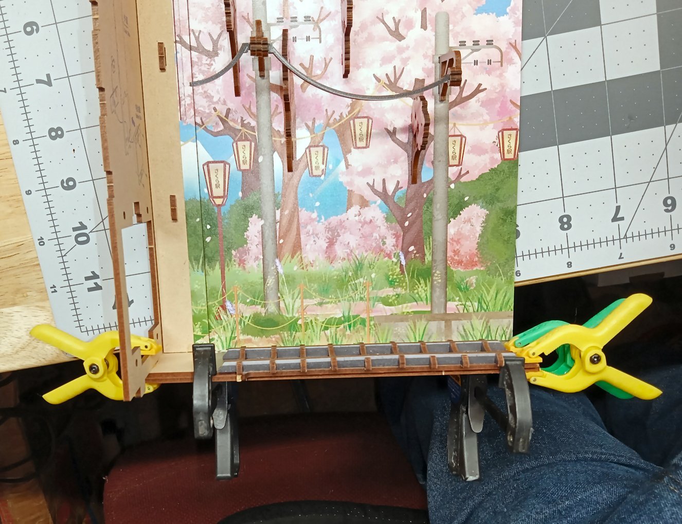
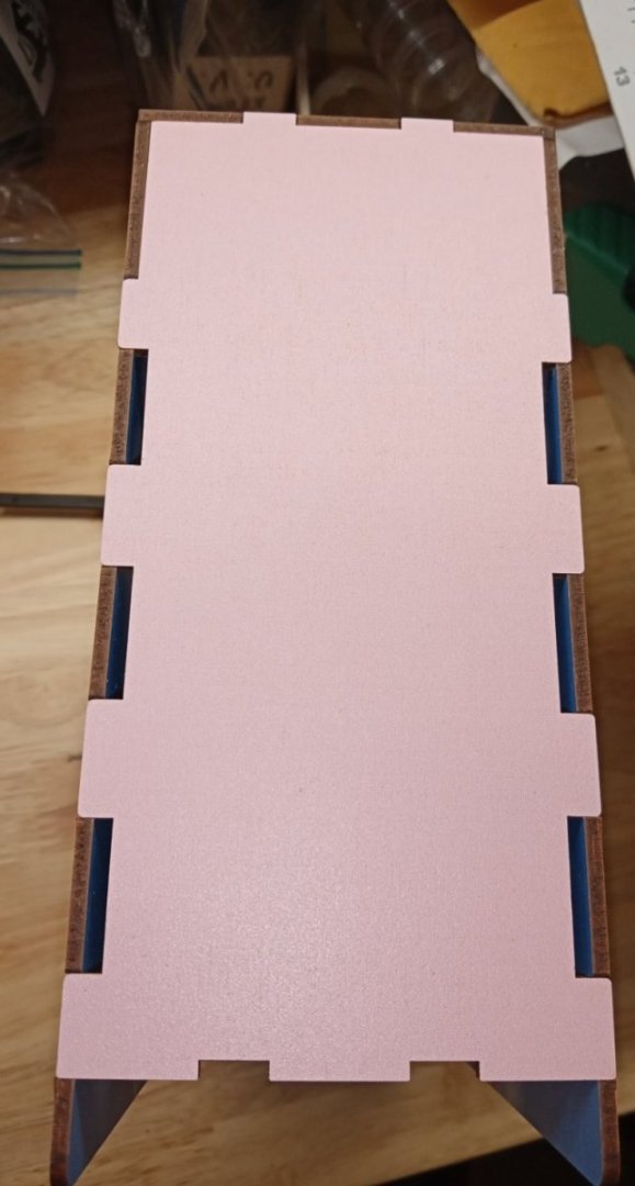
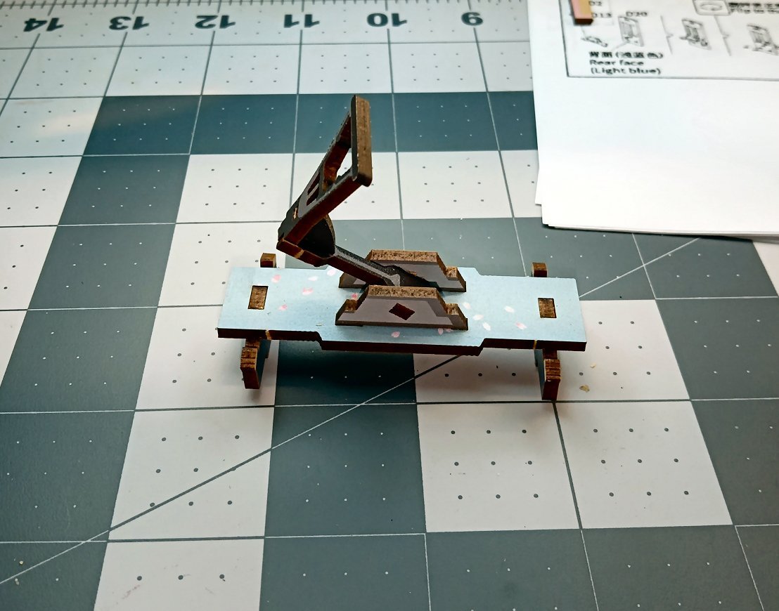
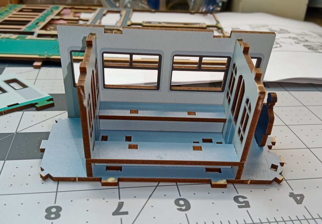
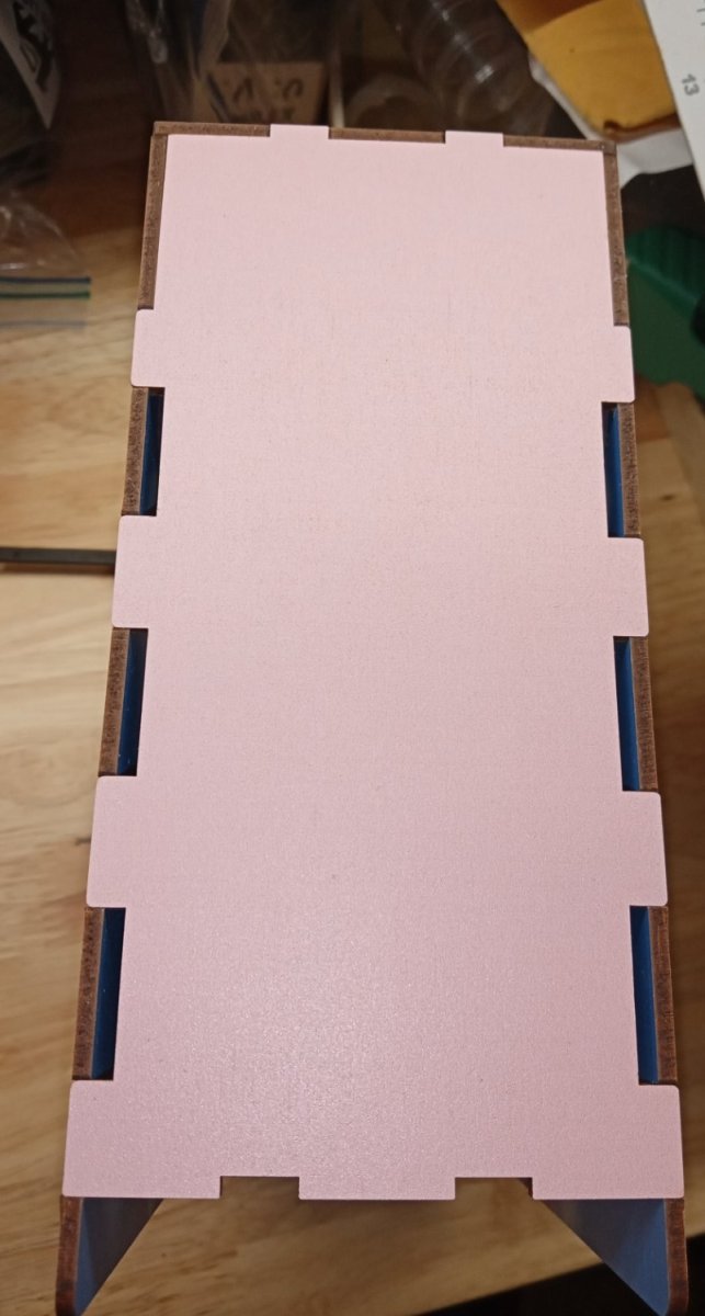
The next step is to assemble one side of the box, the spine and the back book cover. The picture below shows the other half of the base is in place to help- with aligning the two upright sections. Both sides of the base have an upper (printed) plate and a lower un-printed plate. In the picture all four are in place.
I glued just the book back to the spine corner first, and then after it set, I glued the base to both. This let me play with the alignment to get that corner right for a little longer.
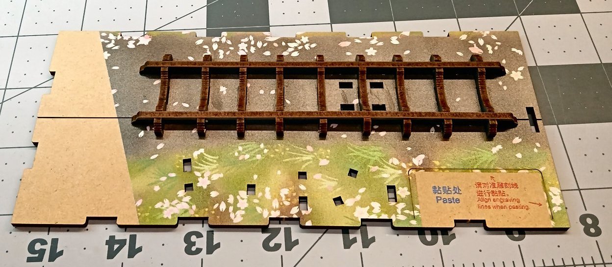
I then glued the front and back edges of the two right hand base pieces. I clamped all the joints I could and let it sit overnight. The width of the two base pieces is slightly different, I assume to help align the two sides later. The lower base piece is a little wider than the top one, so I stuck a piece of the scrap from the MDF between the underside of the track and the lower base piece. This allowed me to clamp the base to the side, without damaging the track.
Notice the slot at the front corners of the bases, after the case is assembled, there is a two prong MDF staple that will lock the two base sections together here at the front.
Here is a closeup off the scrap piece I used to extend the edge of the upper base piece, for clamping. It has a blue lower edge.
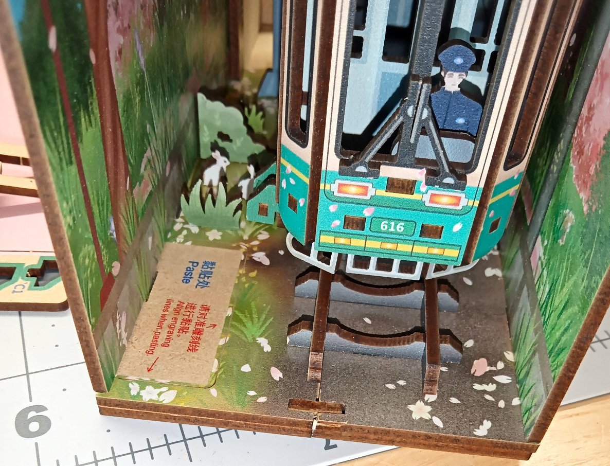
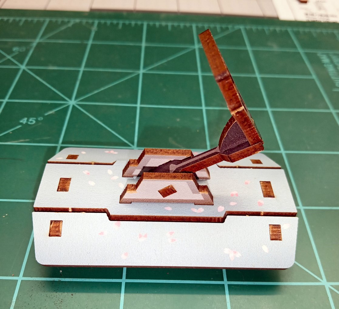
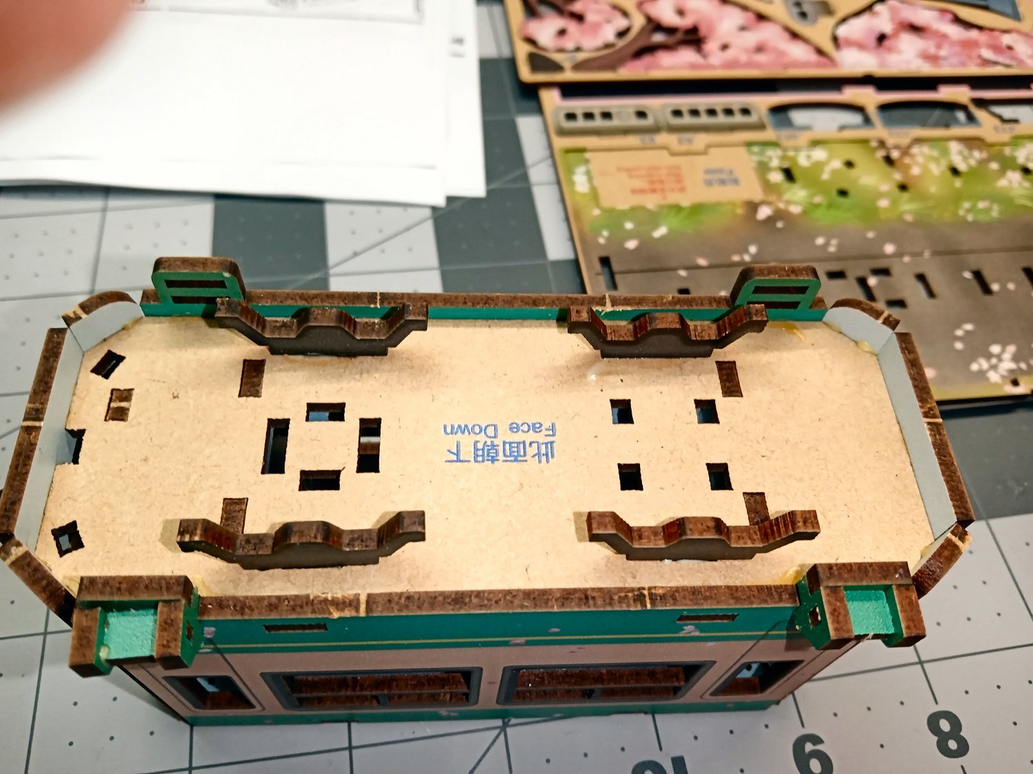
Next, I installed the tram. The instructions have you do this now. I should have done this before attaching the base to the side, as I had a hard time locating the tabs in the pedestals with the ones in the base. The tram completely blocked viewing this connection. I ended up having to sand the tabs down and add a little extra glue in the sockets, to get this in place.
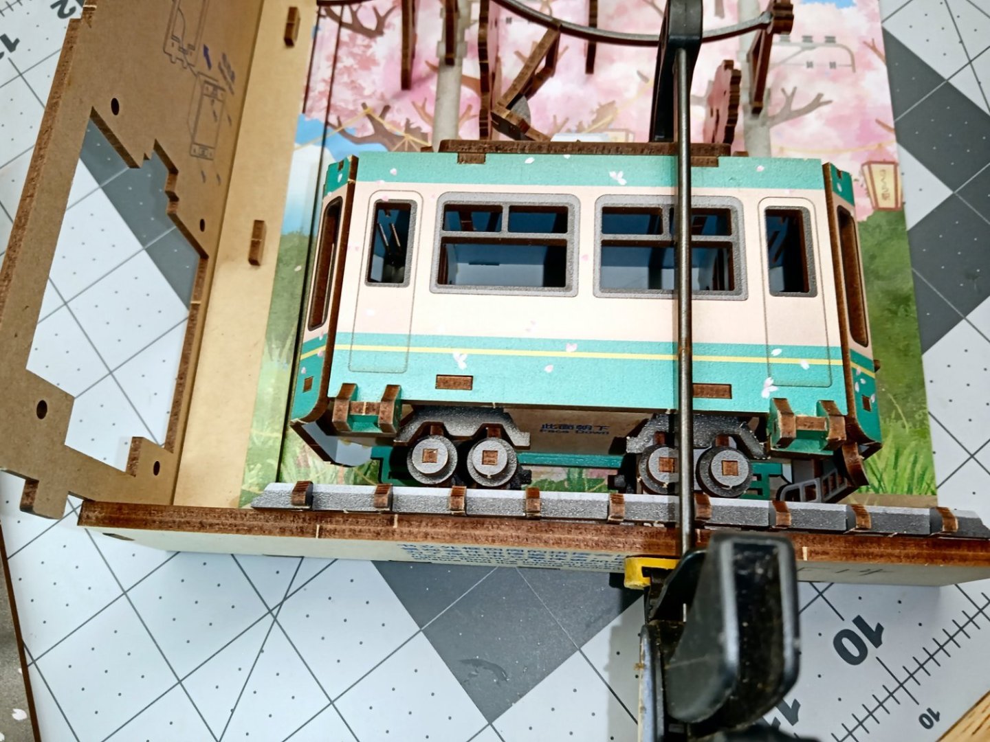
I initially clamped the tram to the base, but noticed that it was causing the tram to lean to one side. I removed the clamp, and set the assembly upright on the workbench. I let gravity do its’ thing, overnight.
Now it is time to work on the other side of the model. The instructions have you attach the base to the side now. As I am gluing the joints, I will wait until everything is ready to go together to do that. The fitment of the base sections to the side on this assembly is not as tight as the other section, and the “wall” will not stay in place. Glue will be required, so waiting is best for now.
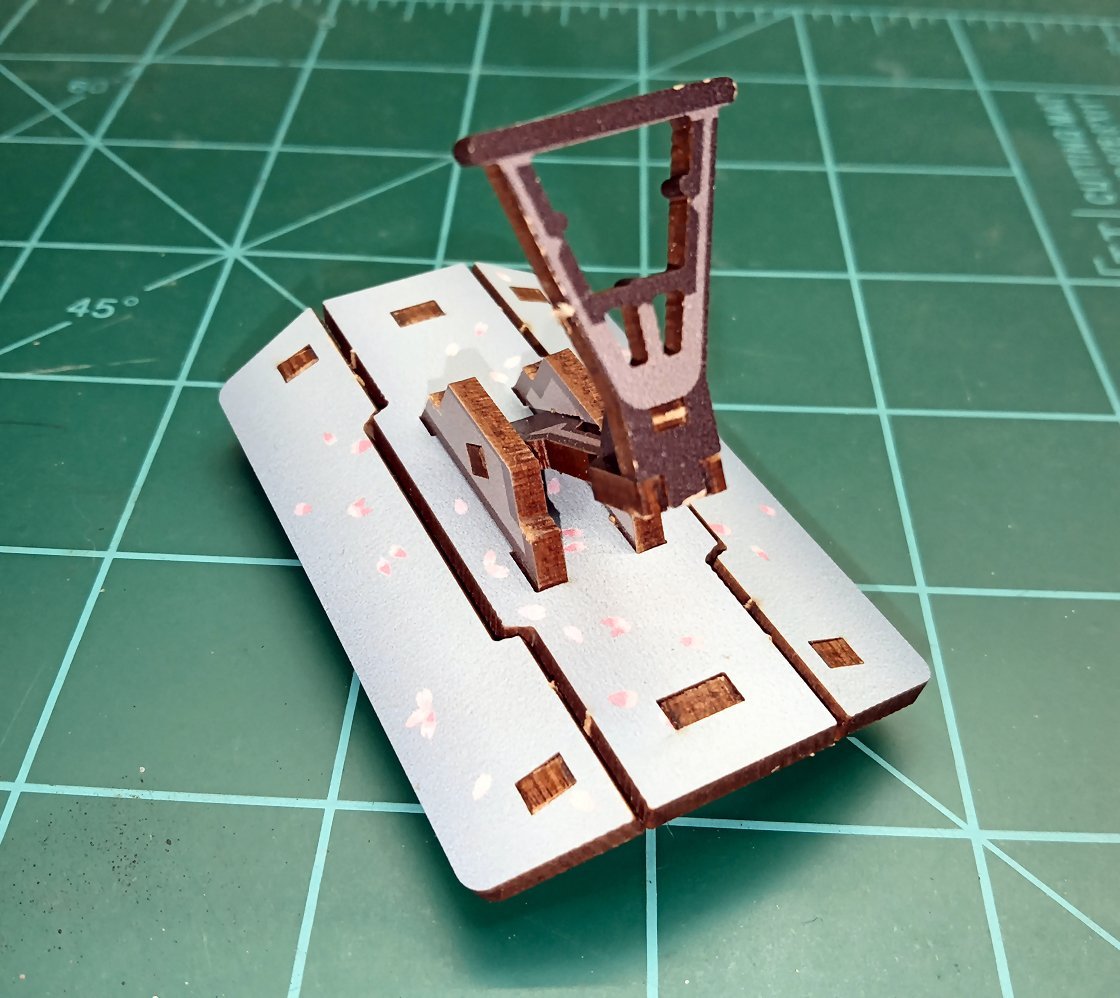
I attached the two passengers to the sidewalk block next. You are to glue the sidewalk to the base, at this point, but once again I’m going to wait and glue it in after the case is assembled.
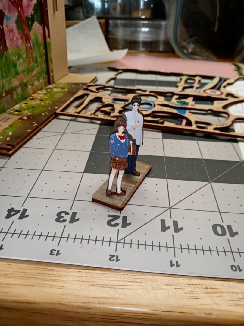
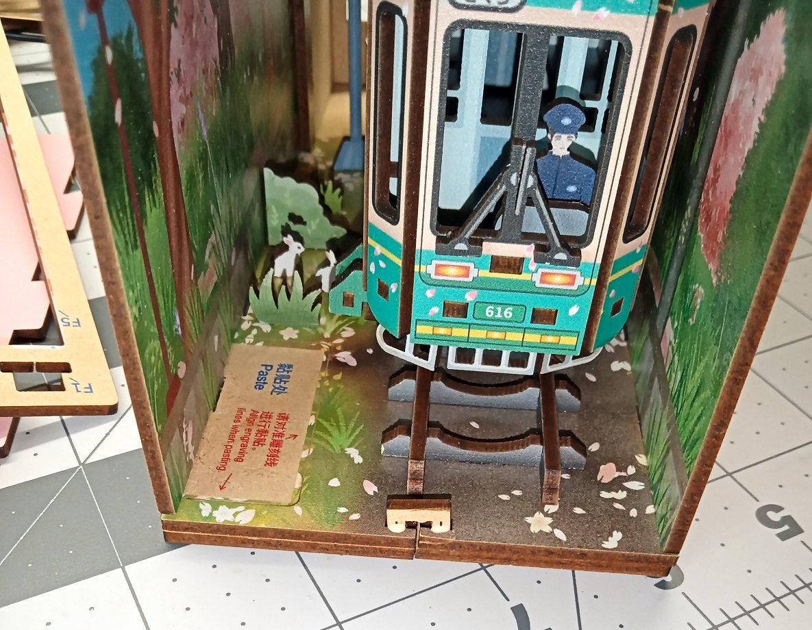
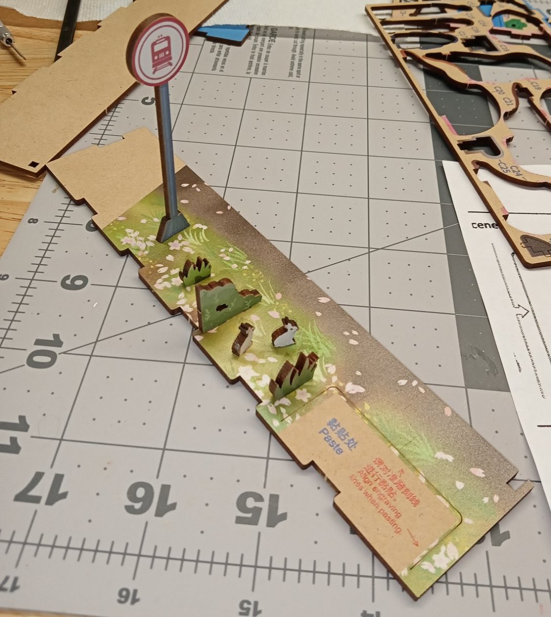
Here is a picture of the sidewalk/passengers just set in place for now. At the front bottom edge of the sidewalk, you can just see the scribe mark for locating this assembly.
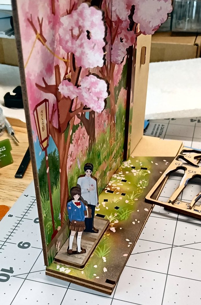
Next some scenery elements are installed behind the sidewalk area: a train sign, some grass cutouts, and a couple of white rabbits.

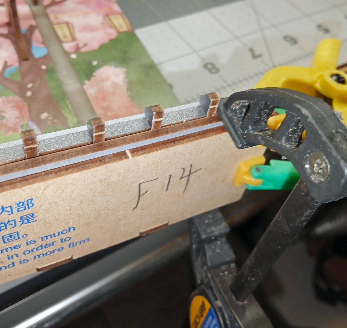
This is a picture of the MDF staple used to hold the front of the base halves together (Part F13). In the shot you can also see one of the other features of the kit, there are extra copies of many of the smaller parts, in case any fall into the black hole that such so typically disappear into.
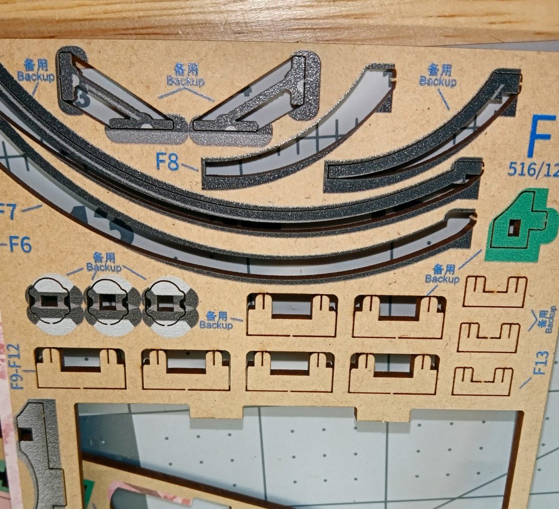
Here is the staple being inserted, and after it was forced flush.
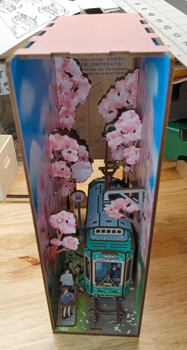
I next assembled the book cover side to the base and spine, the top was left unglued, as the overhead light assembly still has to be made. I also glued the sidewalk assembly in at this point.
I temporarily inserted the top, to hold everything in place. You can see the gaps between the top and the upper edges where the light assembly will go.

The rest of this build will continue in January, after all the family holiday activities are done.
- hof00, Ryland Craze, yvesvidal and 10 others
-
13
-
Part 03
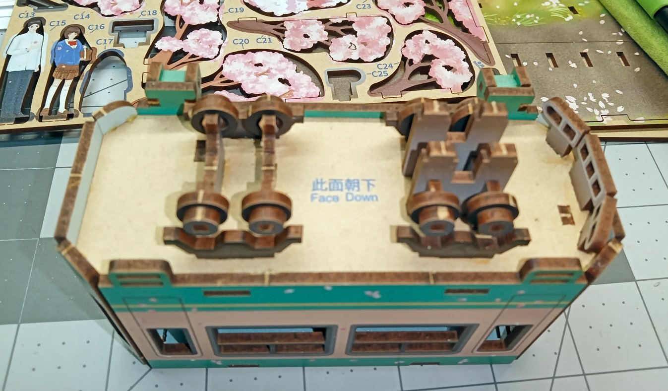
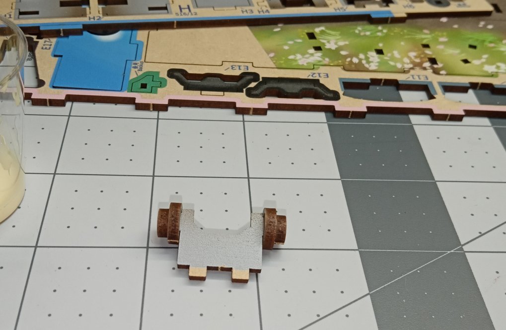
The next steps in building the tram, are to install the trucks.
The four truck frames are installed next.
Now the previously build wheel assemblies are glued on. The wheel/axle assemblies are keyed, so that they can’t be installed in the wrong spot. After the are in the two mounting pedestals are glued in.
I returned to the top of the tram. The roof pedestal ring was glued to the roof. The roof has the position of this rectangular ring etched on the surface. After that, the power pole assembly is put on. There are tabs that position it in place. Lastly two grills are put on, one at each end. I also surface glued the headlights at each end. I should have taken more photos, but sort of fell into the rhythm of installing parts.
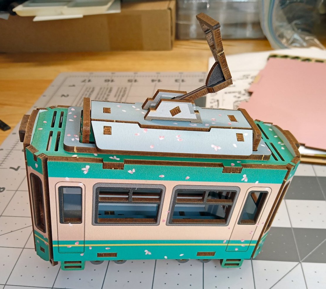
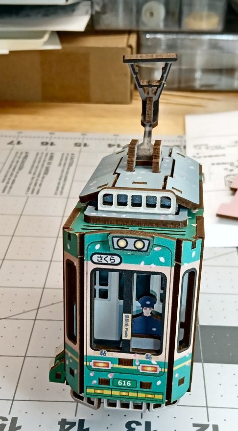
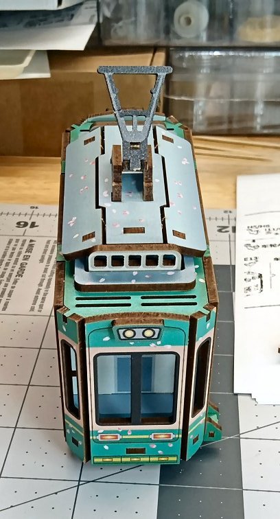
To finish the tram, the last step was to glue on the wipers.
Next the base with the tracks is built.
A number of the ties are glued on to one side of the two-piece base.
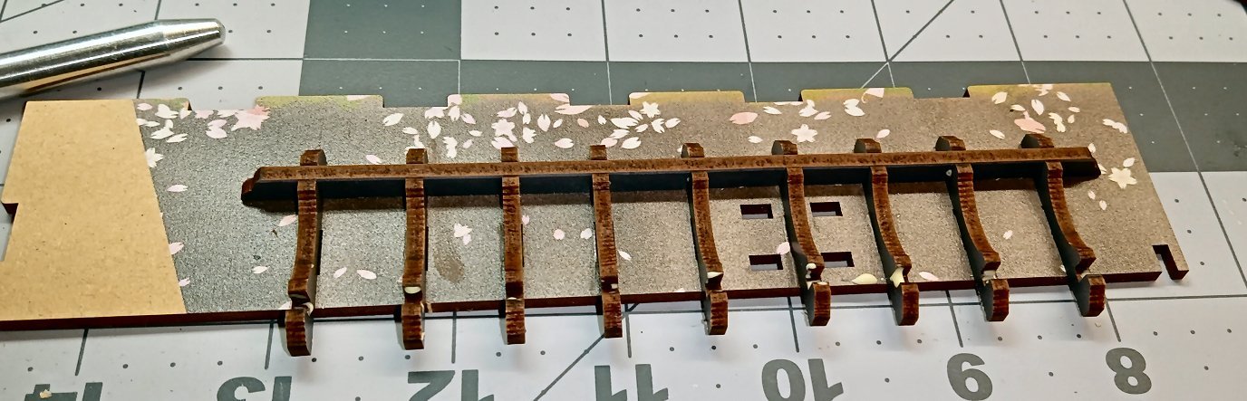
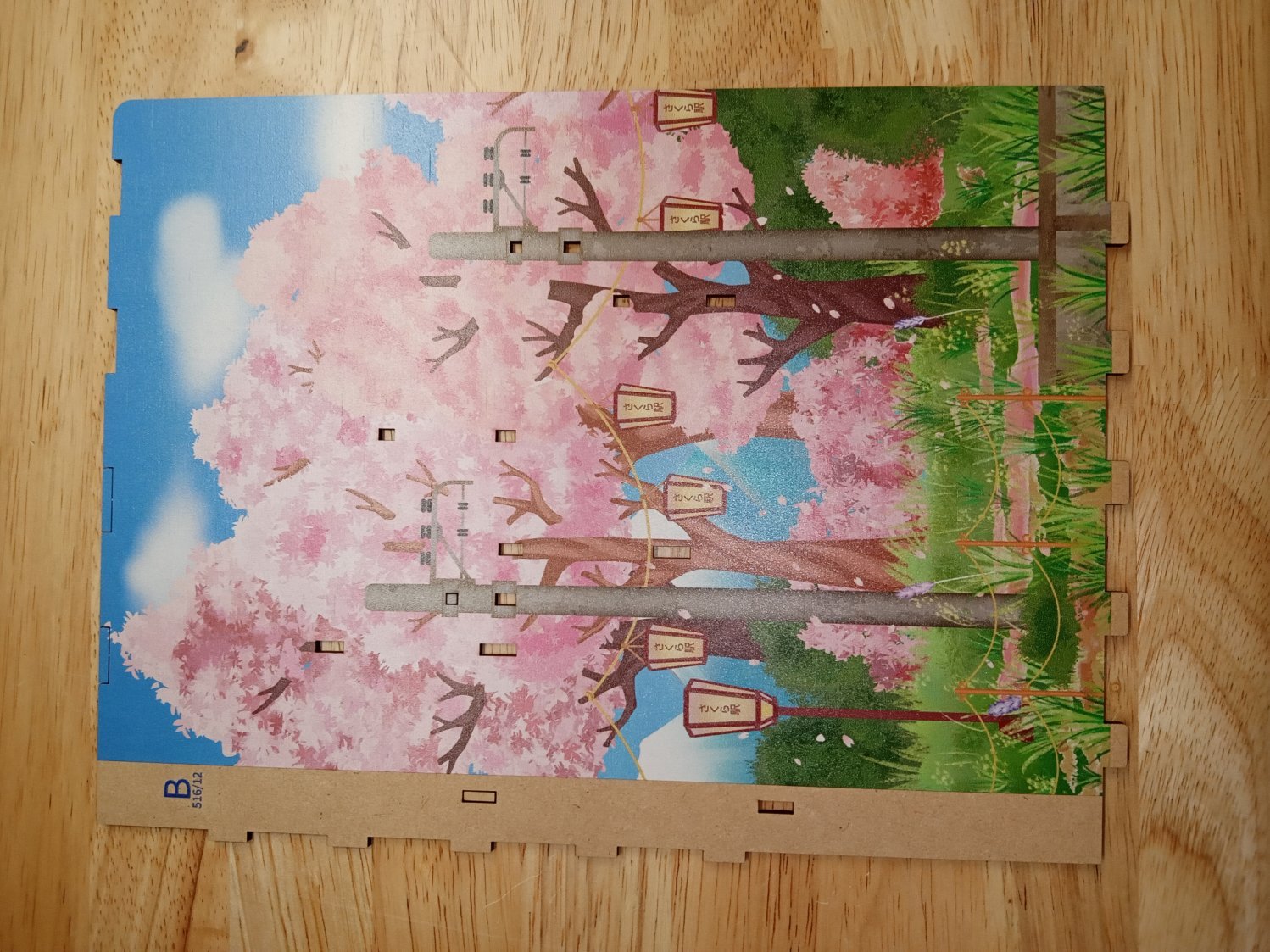
The two rails are then glued on. When the rail that hangs over the side of the first base half is pressed into place, I slid the other half under it to support the ties. The next picture shows the track with both base pieces. The two bases are not glued to each other until later. The un-painted area of the bases is where the background mirror will sit.
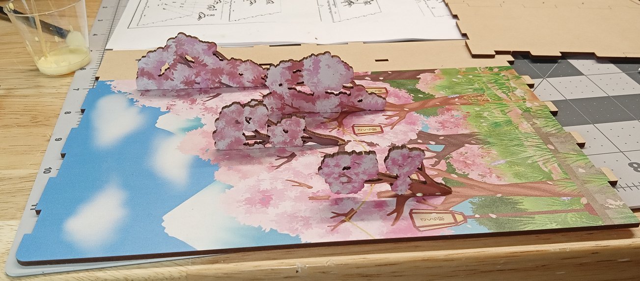
The two side pieces (The "Cover" and "Back" of the book) are next to be built. The 3D cheery blossom covered branches are installed. The branches are keyed, but care must still be used in getting them in the right spot. Look at the instructions, as not all of the branches are installed at this point. There are power lines that go on before some of the branches.
Here is the front book cover side with the initial branches attached.
Once these branches are in, there is a plate installed at the back that will hold one side of the mirror. It is held in place with two long MDF staples, that slot into it and the main assembly under it. The slot is just above the top most branch.
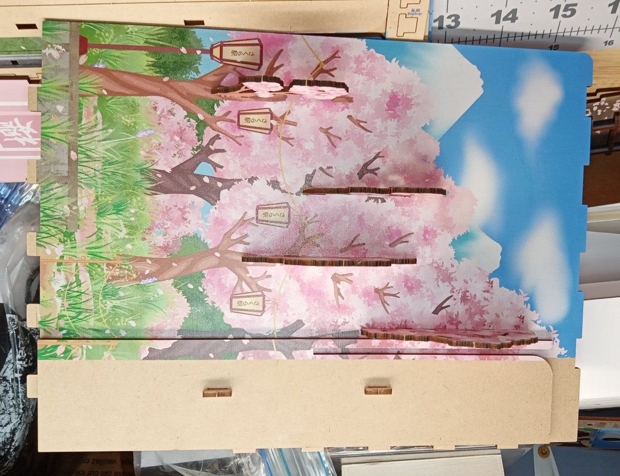
This is a picture of the initial branches attached to the back book cover. This side will also have a mirror mount installed, later.

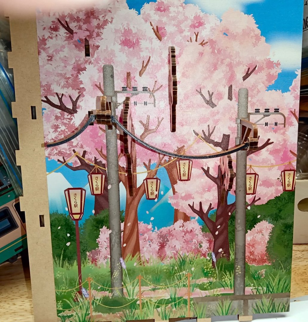
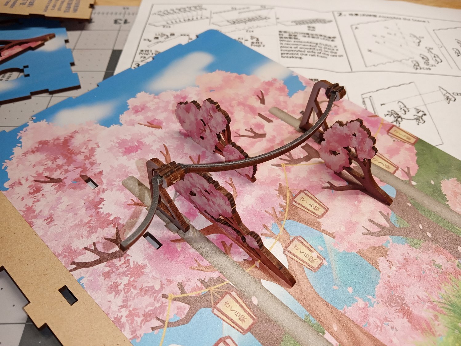
The instructions have you building the power lines before installing them on the background. I choose to build them on the background. I ended up breaking one of the supports, but if I had not, I likely would have had the supports at the wrong spots in the assembly. The only problem with the broken support, was having to hold the two parts together while the glue set.
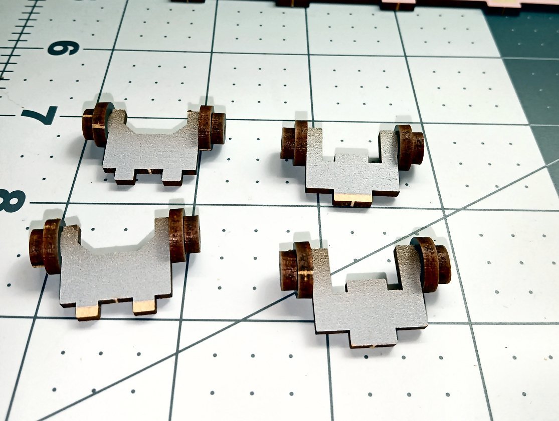
Anyway, here are the parts to one of the supports. The other support is the same, except only one side gets an insulator block.
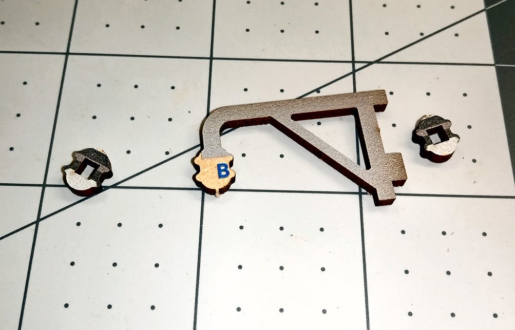
In the picture below you can see I glued the insulator blocks in with the silver part toward the “Metal” frame, when I went to glue up the second support, the back side showed that it should be the other way around! Luckily the glue had not set on the first one, so I was able to correct the problem.
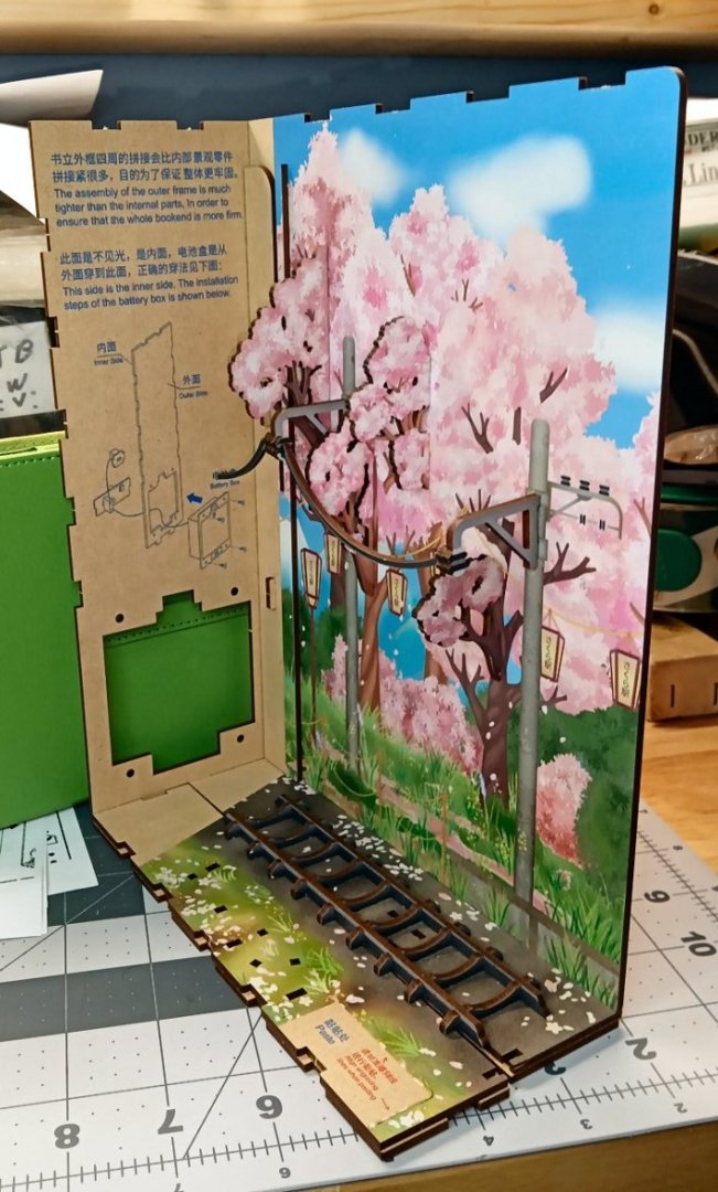
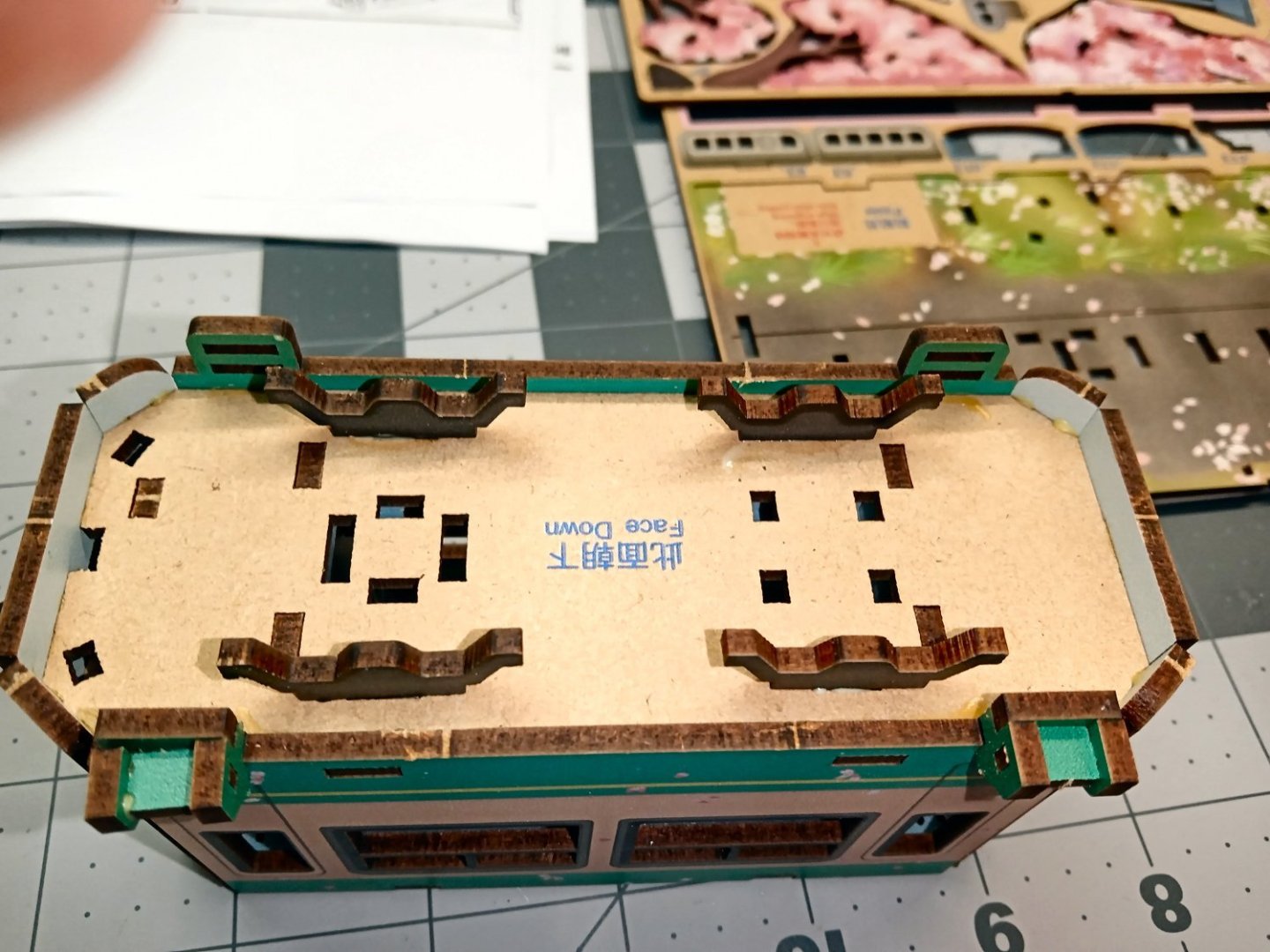
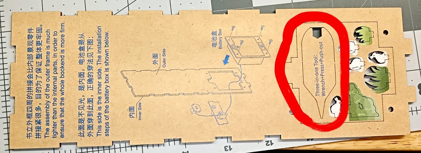
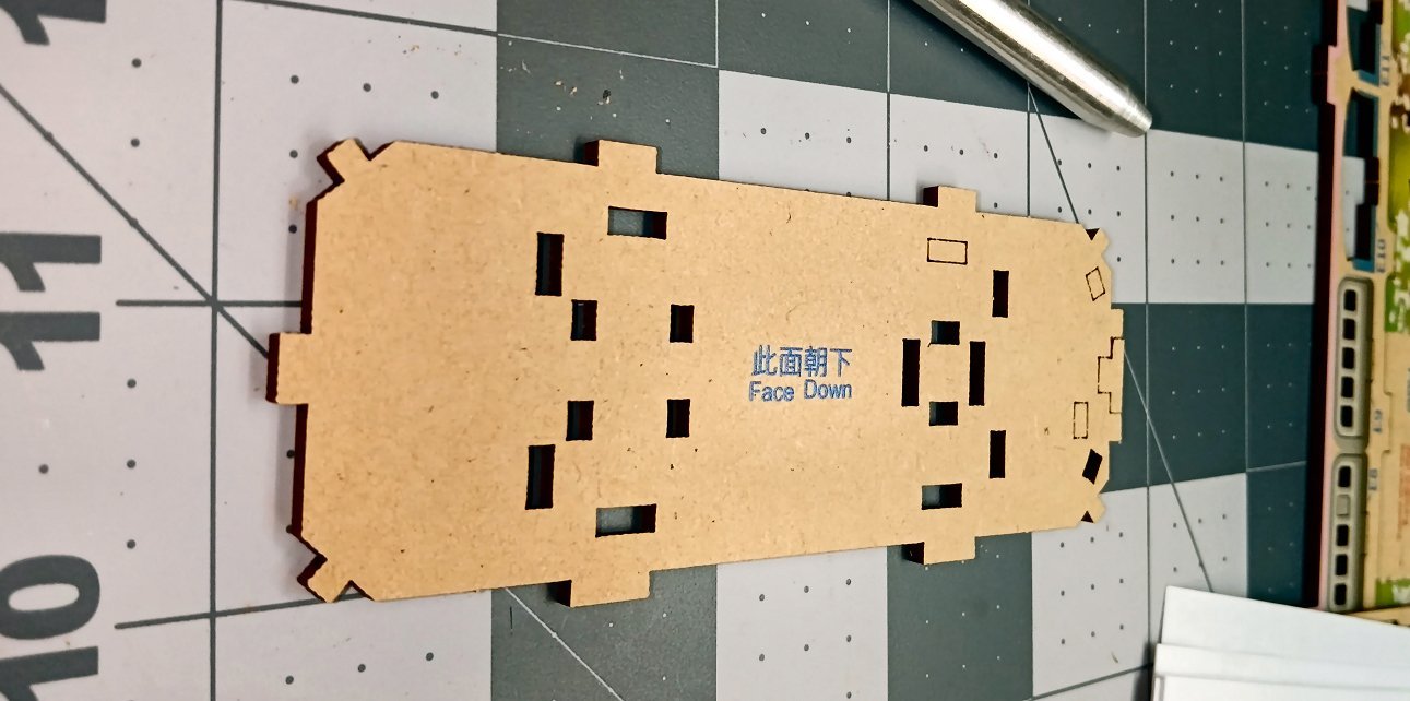
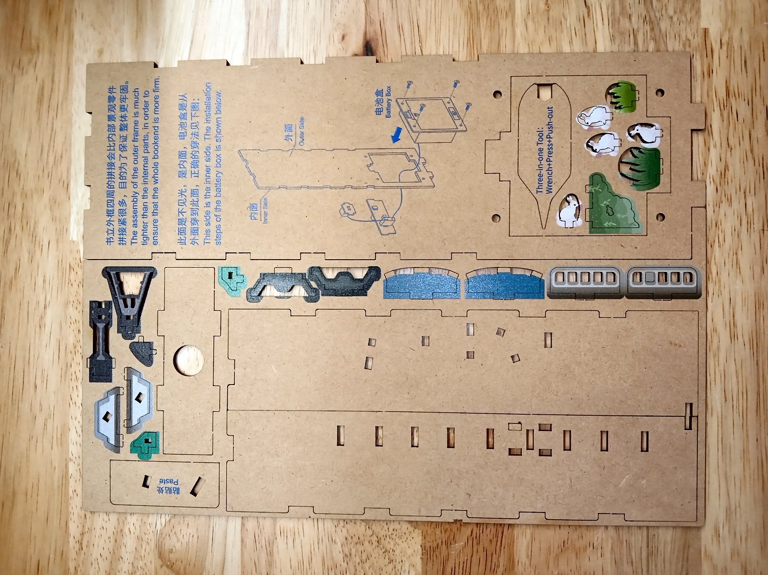
The next picture is the inside of the back of the diorama, or spine of the book. I like the fact that they explain about which side to place inward, and why. While, in this case, it is obvious, as the other side is printed, it is something I had not thought about with laser cut kits in general. Good to know for future builds. Also notice that the kit supplies a laser cut wrench for tightening the bolts for the battery pack, a nice touch! They also supply a screw driver to be used for the same purpose, not a good one, but sufficient for this application (See the last picture in Part 1).
If I was installing the battery box, it would go in like this.
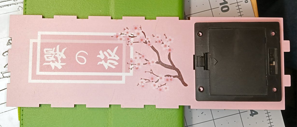
I’m not going to attach it, as the nuts for the bolts will be captured between this part, and the background mirror. I plan to build a dedicated power supply that will run all my Book End kits, so I don’t want to have all the wires locked away. “Build a supply”, may end up being “Buy a plug in one”, but I still need access to the wires.
-
Part 02
The “blotches” you see on some parts, are fallen cherry blossoms, not paint defects.
I will be writing this thread so as to aid younger modelers, as the kit is geared toward them. I have so far not found any tab/slot combinations that required excessive force to match up, but some carefully applied force is needed. For smaller assemblies I used the blunt end of the handle to apply the force. I used a little PVA glue on the tabs. This is not really needed, as the fit is strong enough, but it does not hurt either. I used a toothpick for applying the glue. There are some surface mounted parts, like the headlight, and windshield wipers that will have to be glued on.
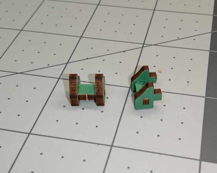
Construction starts with the tram car.
The trolley pole and roof are the first parts. All the attachment bridges between the MDF sheets and the parts are very fine, and I broke those I could see by using a medium chisel point X-Acto blade pushed in from both sides. After freeing as many as I could see, I used the handle end to rotate them, breaking the rest, and pushed the part out.
I was a little rough with the power pole piece and bent and cracked it. I, thereafter, learned to apply assembly pressure a little more carefully. I will wick a little thin super glue into the cracked area, to repair this.
Next are the tram wheel assemblies. The wheels are two parts, the wheel disk is held in place by the rim/tread piece, and can actually turn. Not important for this model, but I thought it was a nice touch. While a simple kit, the designer took time to do it right. Notice that the supports are keyed so that each of the wheel sets go into separate two axle trucks. The supports with the slots will have supports installed later, for attaching the car to the base.
This shows the two sides of the tram floor, the printed top and unprinted bottom. I think that a lot of care, other than the instruction sheets, was taken in the design, as you can see that the bottom of the part is clearly printed on the unfinished side. This would aid younger modelers. The outlined rectangular areas are assembly slots I have not pushed out yet.

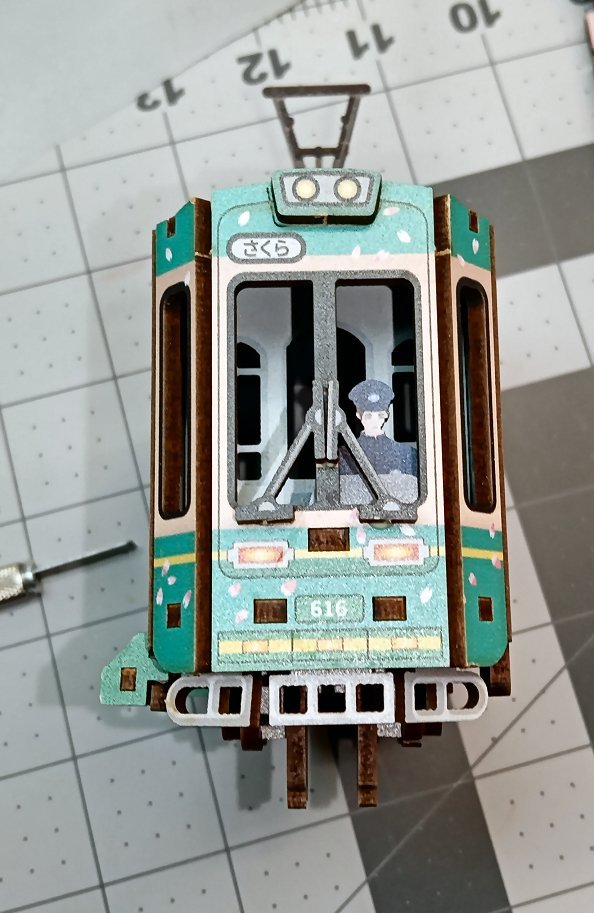
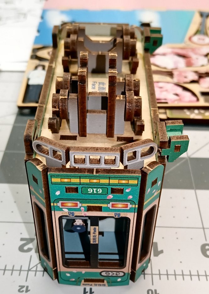
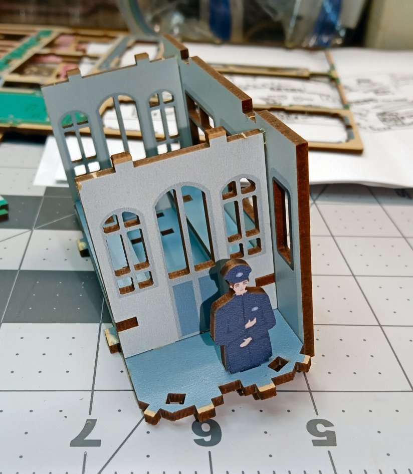
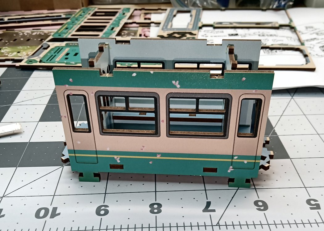
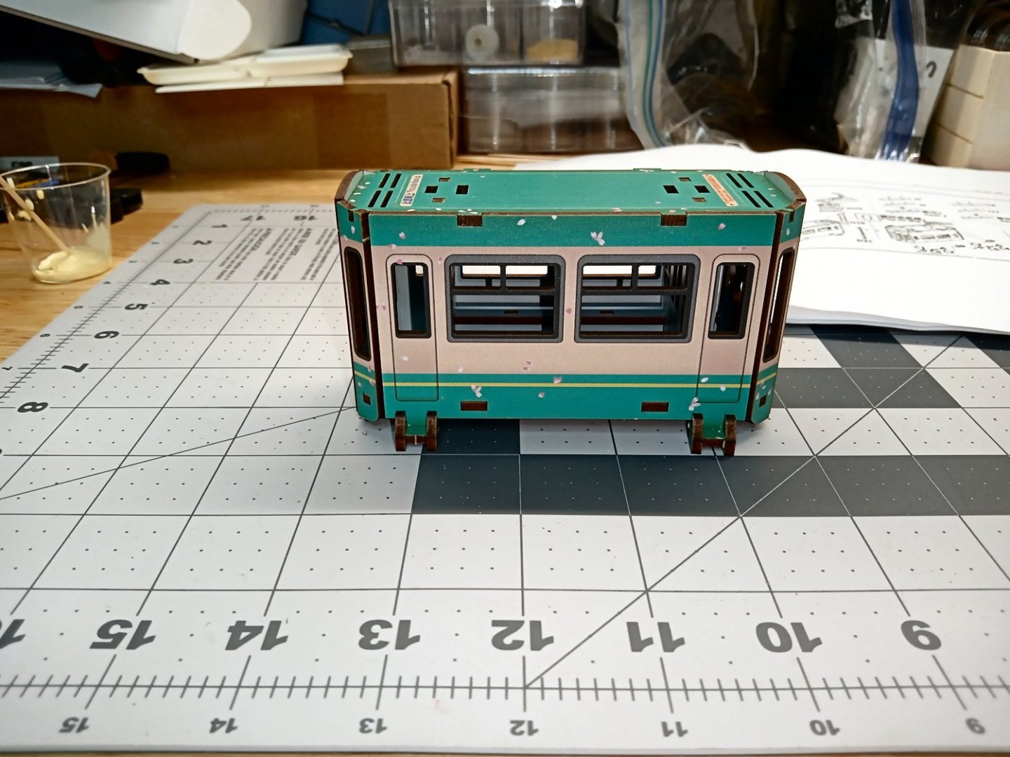
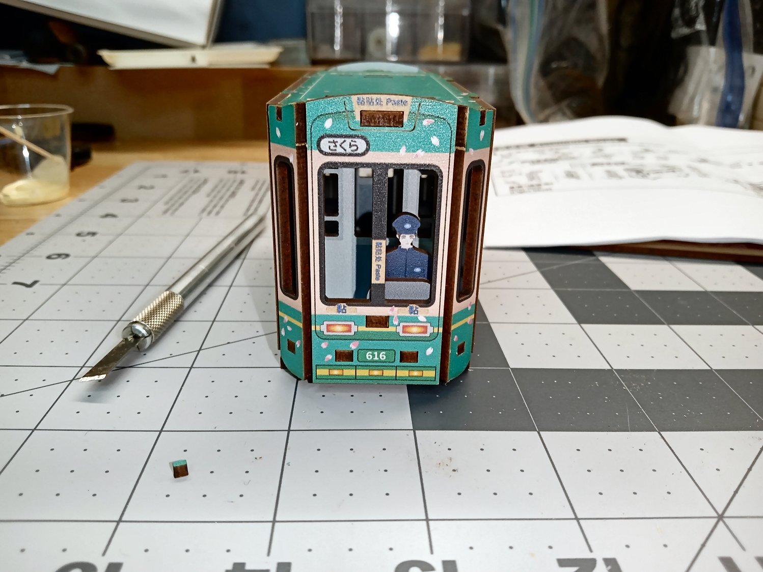
These pictures show the main tram body mostly assembled. The first shows the interior bulk heads, seats, one side, and the engineer in place.
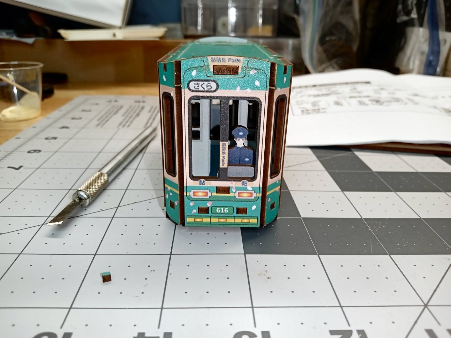
This one is a shot from the front of the tram.
Here the other side and then the roof have been installed
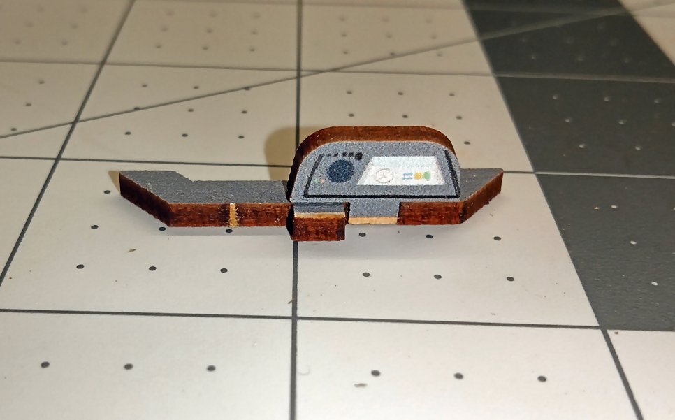
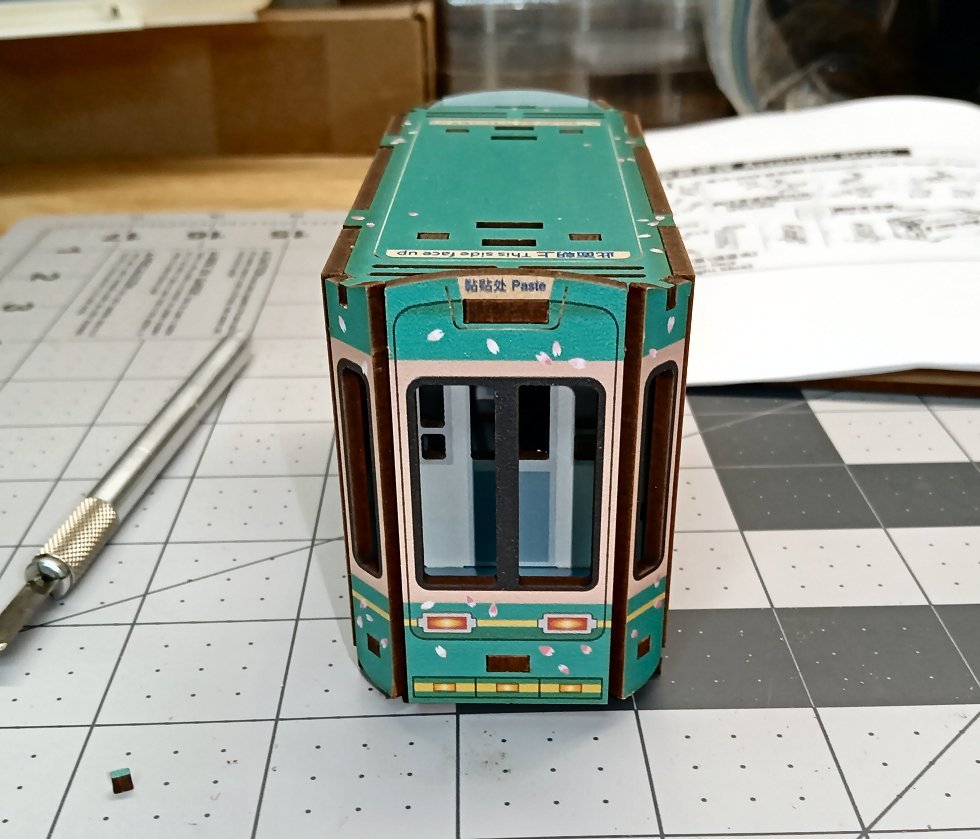
Next the operators console is assembled. I found it interesting that the designer actually had a console display included, even though it will never be seen, once the tram is finished, as it points toward the operator! My respects to him!
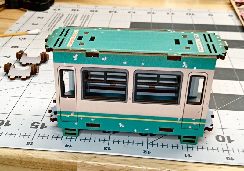
These picture shows the completed main body of the tram, from both ends, after the corners were installed. There is no window included glazing in the kit.
The raw wood areas are where untabbed surface mounted pieces will be glued on later. Things like the headlight, windshield wipers etc.
Next, the steps on the passenger loading side are assembled and installed. I managed to mess this up, and not fully press one step into place, and then broke the support when I tried to press it in a little later, as the glue had set. It took a little trimming, but I was able to fix it. Naturally it was the step at the front of the car, one of the most visible areas on the finished model!
- Old Collingwood, hof00, Egilman and 7 others
-
10
-
Part 01
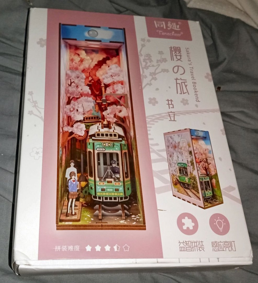
I decided to start on one of a new type of kits I’ve seen. They are book shaped and sized dioramas, with color printed, and laser cut wood parts. Some of the more complex kits have printed paper sheets that you have to cut out the parts from. The idea is to slip the diorama between some real books, on a shelf. They include battery packs for the LEDs, but I will be building a dedicated power supply to power the several kits I have. They are basically the wooden equivalent of the Plastic “Snap Tite” models. They are designed for 14 years and up, so most are not too difficult, but make an interesting, different type of build. All my finished models will be displayed in an enclosed display to keep the dust off them. While they are called “Book End’ kits, they are too light to serve as such, though if you attached them to a horizontal piece that the real books sit on (like a regular book end) they could be used, as such. They would definitely have to have, at least, the shell pieces glued, in this case.
This one is one of the less difficult ones. All the model parts are printed on laser cut MDF pieces. Some of the others in my queue involved cutting out and assembling parts printed on paper sheets. Two of these are, a library and a book store, where you have to “assemble” the books by gluing covers on blocks, and building and fabric covering the chairs. None should take over a week. This kit would be a weekend project, maybe one day, if worked on for the whole day. Mine will take a month or so, as I only get a couple of hours at a time, and the Christmas holiday, family time is coming up. As far as I can tell, this kit is out of production, though an, if possible, less detailed and more expensive one is still made.
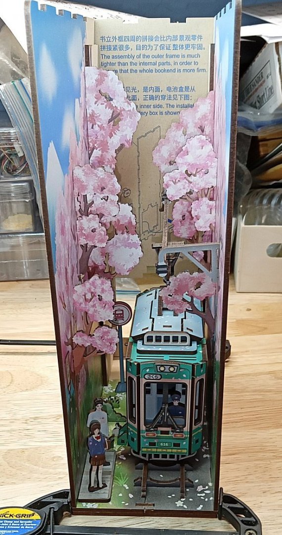
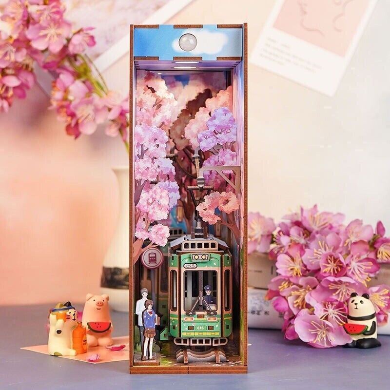
This kit is a train/tram coming out of a cherry tree lined area, with a couple waiting to board at a stop. It is set during the Cherry Blossom Festival time frame. I have a companion kit showing the tram going across a town street. Two interesting notes: Both Japan and China have this type of festival, and the type of cherry tree the festival celebrates produce non-edible fruit!
This kit is printed plywood, a battery box for the LEDs, and a mirror at the back to deepen the scene. There is only one tram car, but the placement of the mirror makes it look like there are two cars. Most of the parts are printed on both sides, except where the one side will be hidden.
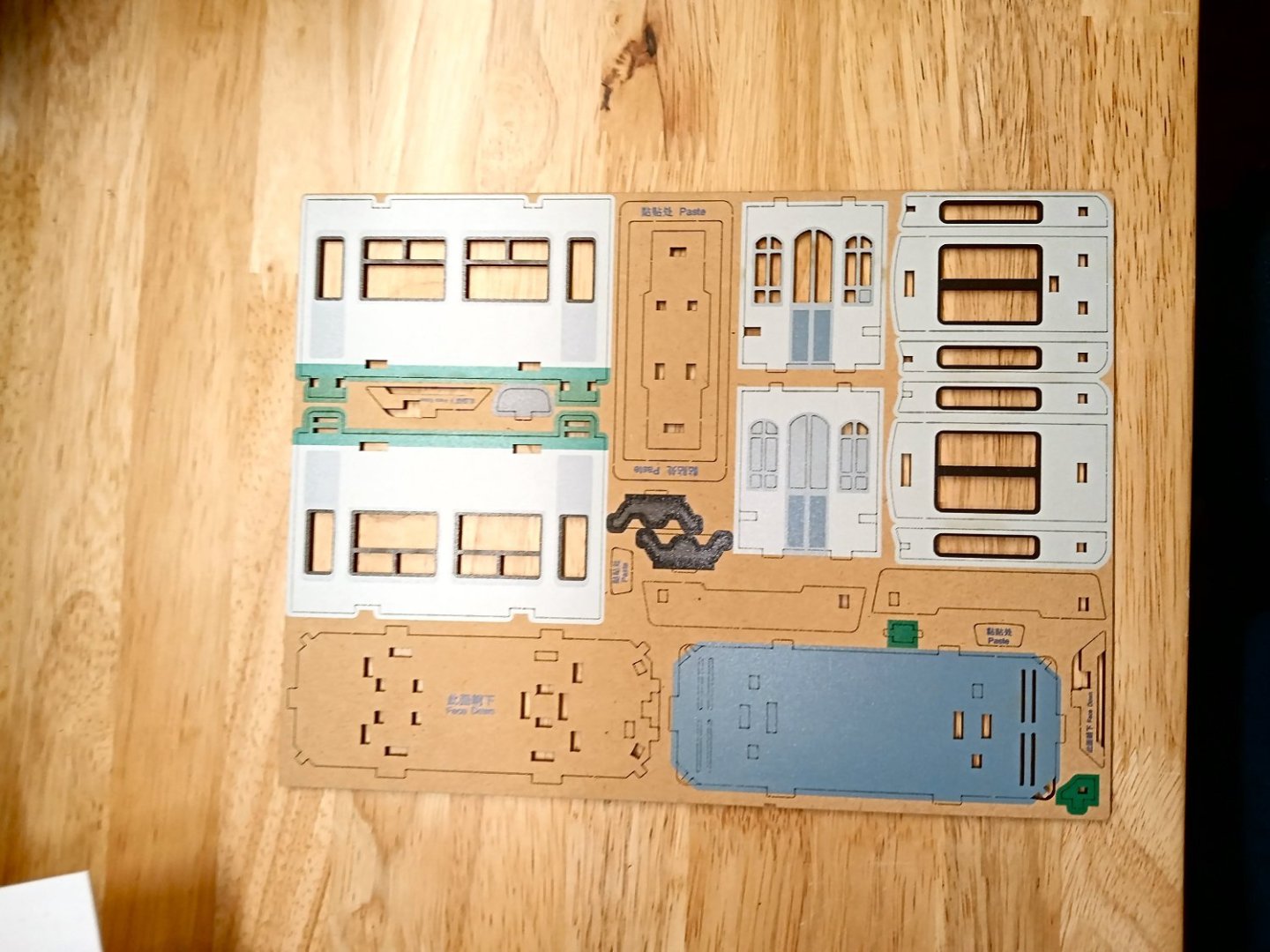
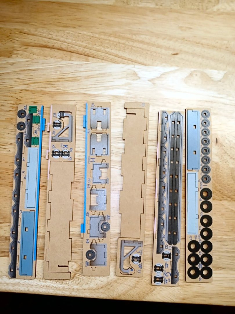
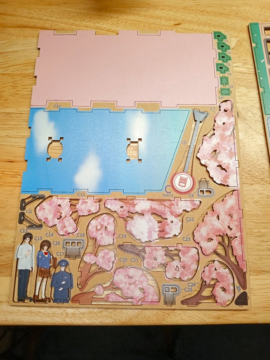
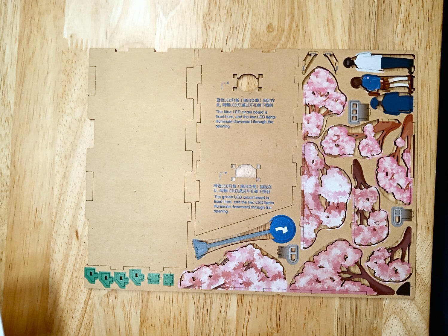
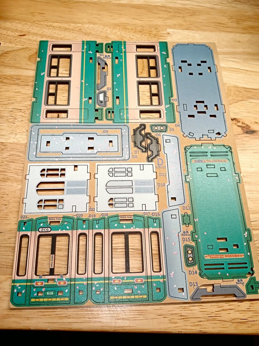
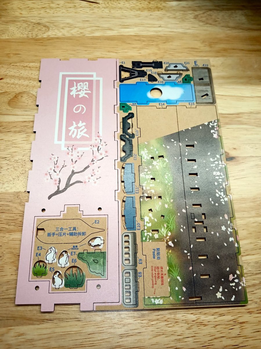
Below are photos of the kit contents. Part 2 will start the construction. I plan to leave the laser cut edges as they come, this is not supposed to be a highly detailed model, just an unusual one.
The only complaint I have with the kit, is that all the pictorial instructions are rather crudely printed on one side of two regular size pieces of paper, with small pictures. I scanned them and blew up the graphics, but the blocky graphics are still hard to read sometimes. At least the part numbers are clearly marked on the wood sheets.
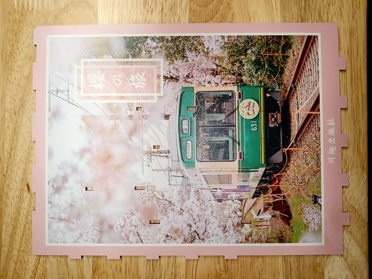
First are a couple of pictures of the boxed kit, and a finished model.
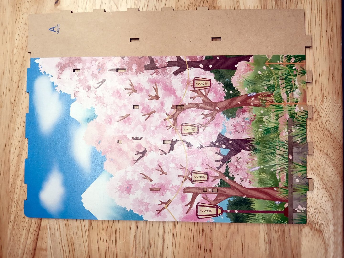
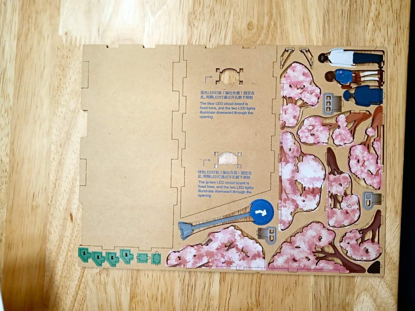
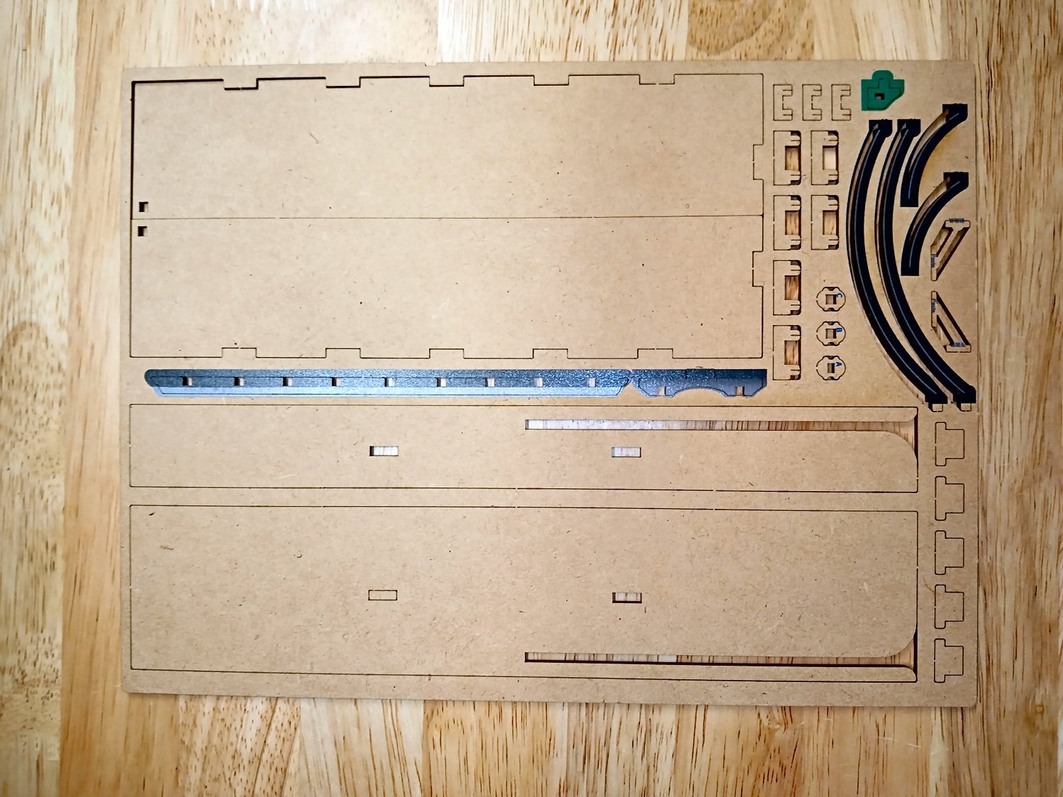
Next are both sides of the plywood sheets. So far in the construction, all the tabs have been keyed so that the parts can’t be assembled incorrectly, and all the tabs and slots have been a tight secure fit, though not so tight as to make assembly overly difficult.
Here are both sides of the front and back “covers” of the “book”. I scanned the picture on the front cover, so that I can glue one to the back side, later, if I find I want to.


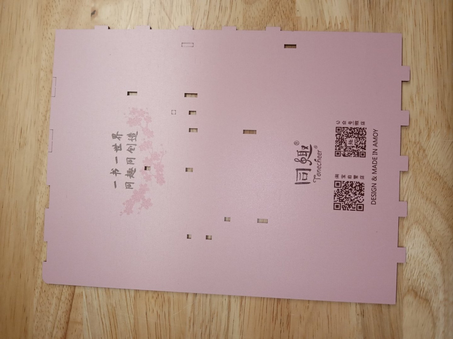
These are both sides of the other sheets


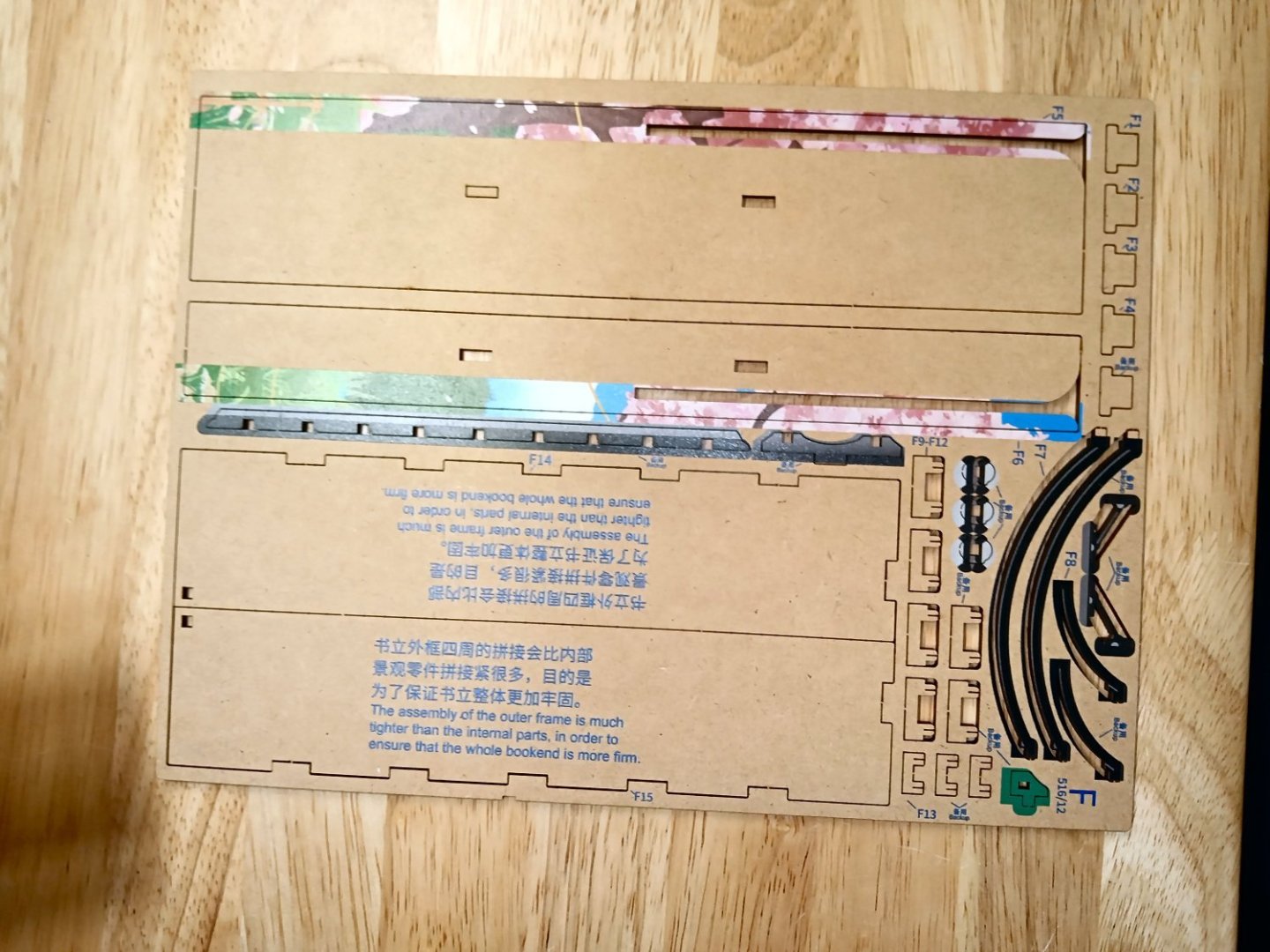
Forgot to take a picture of the back side of these sheets, unfortunately.
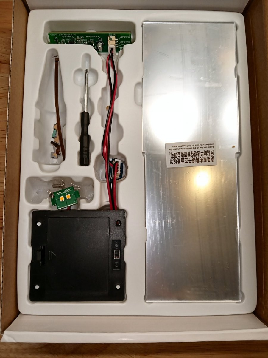
This is a picture of the tray with the LED and battery box, mirror, screw driver, and a few parts that fell out of the sheets, while I was handling them. There is a protective plastic sheet cover on the mirror.


- Egilman, Old Collingwood, mtaylor and 10 others
-
13
-
-
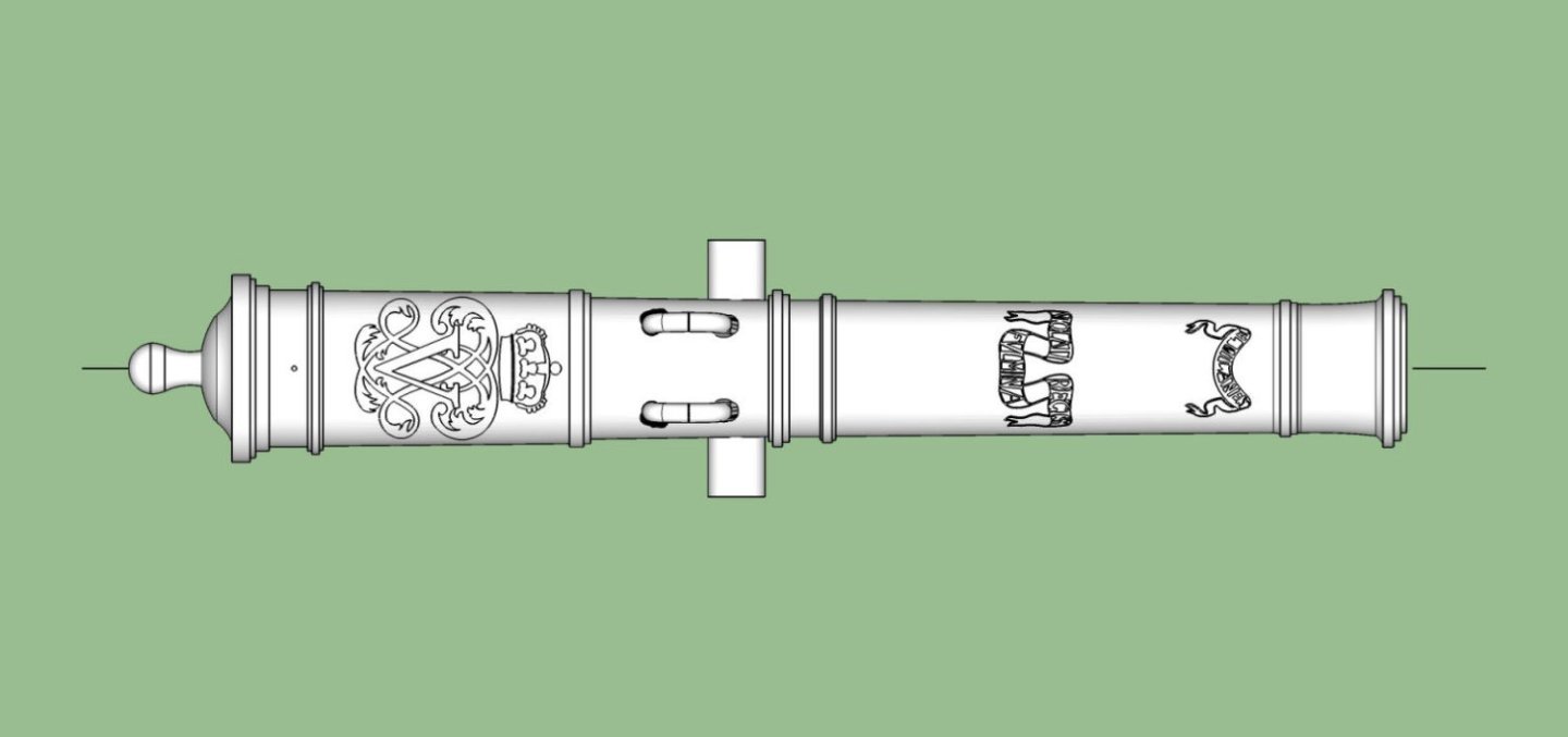
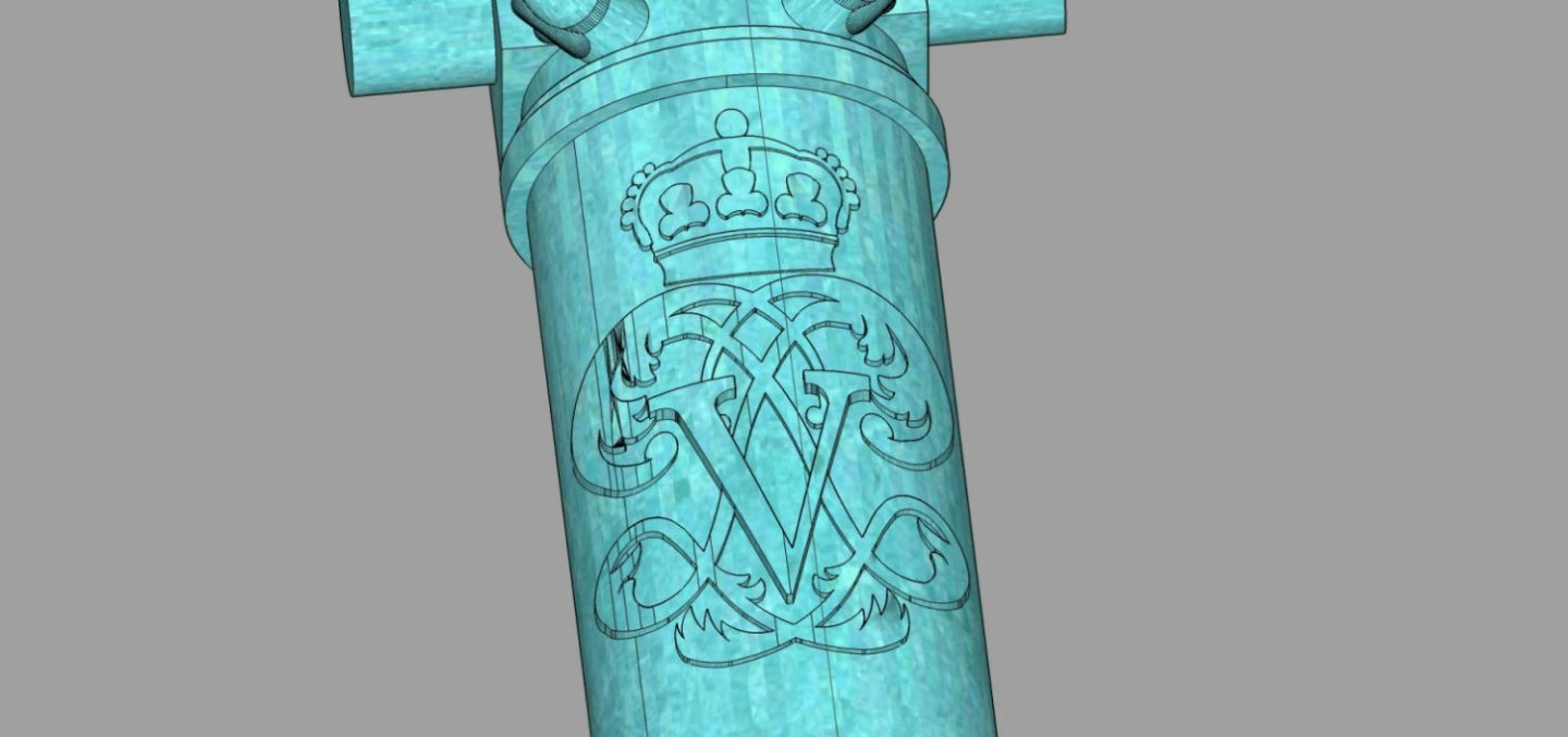
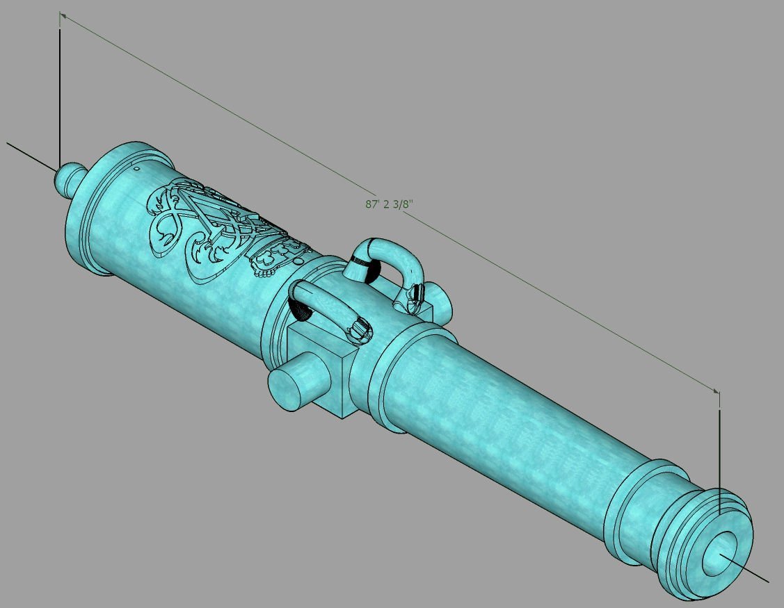
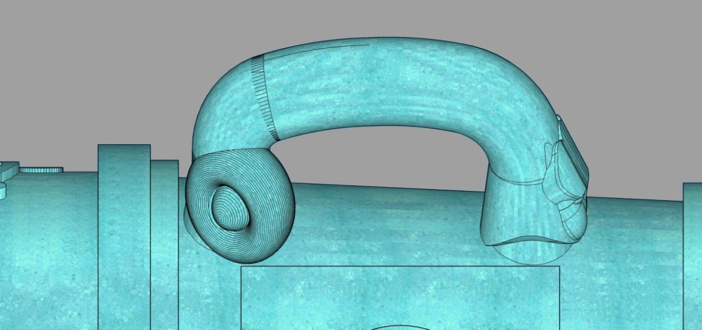
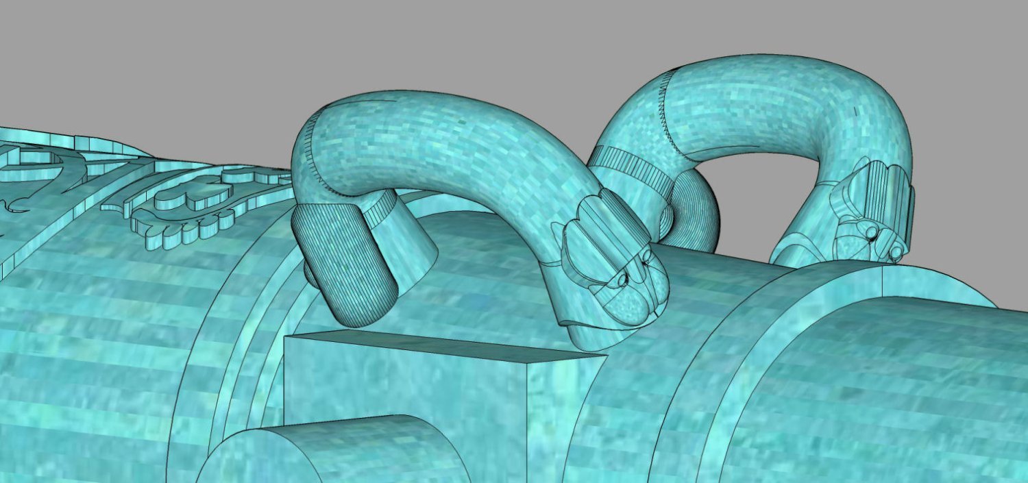
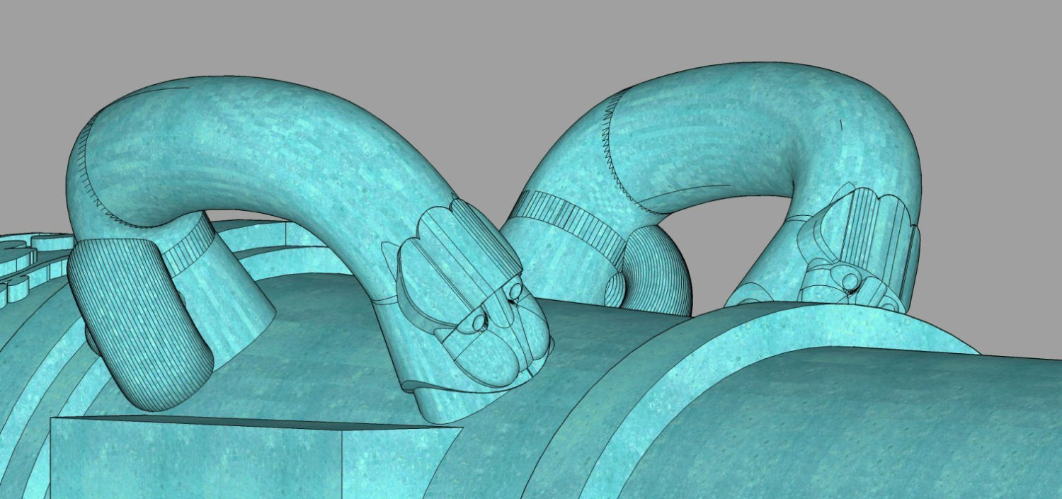
I completed the Spanish 1718 Pattern cannons series. They include 5, 9, 12, 16, and 24 Pounders. The cannons have Sea Monster motif handles, the Banner Quote, and Name ribbon cyphers as well as the Royal Cypher on the breach. The breach cypher has three "layers", and covers most of the upper half of the surface.
I'll be adding more Armstrong-Fredrick sizes this week, and after Christmas, then the Armstrong series in January.
5 Pounder
9 Pounder
12 Pounder
16 Pounder
24 Pounder
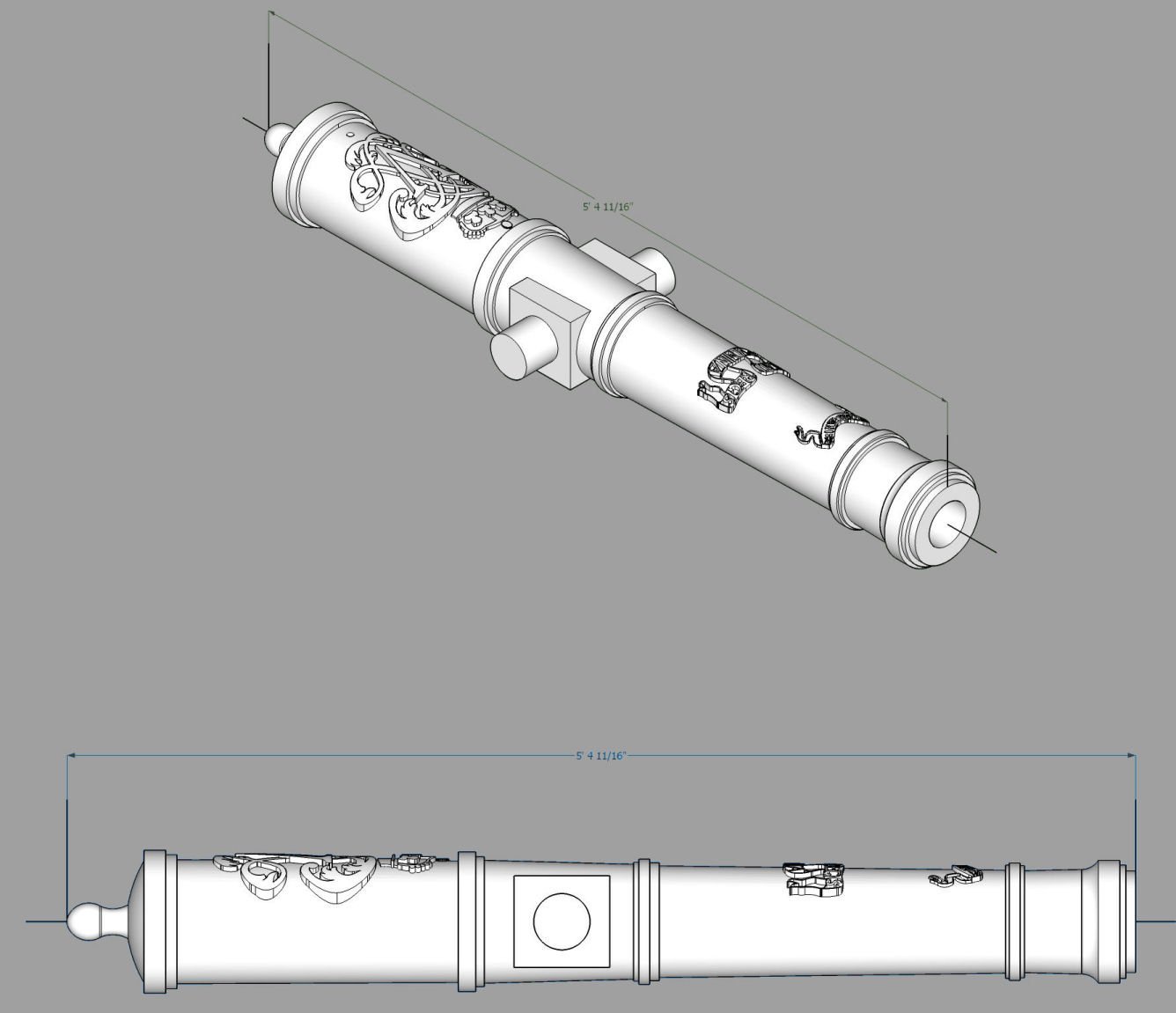
Overhead of 24 Ponder. The scrollwork closest to the muzzle is the cannon's name, the one closest to the trunnions Says roughly "The Queen has been insulted!". The Coat of Arms is for King Phillip 5th.
- scrubbyj427, westwood and mtaylor
-
2
-
 1
1
-
I should finish the Spanish Cannons next week. Integrating all the fancy decorations takes some time. With a break for Christmas, I should finish the other sizes of Fredricks by mid January. The Armstrongs will require creating a new Cypher so about 3 weeks after that.
- myMADNESS78 and mtaylor
-
2
-
-
I've completed the Following Blomefield cannons
6 Pounder: Bore Length 84" Overall Length 94", BL 90 OVL 100.5", BL 102 OVL 113"
9 Pounder: BL 90" OVL 100.5", BL 102 OVL 113", BL 108" OVL 121"
12 Pounder: BL 90" OVL 100", BL 102: OVL 113", BL 108" OVL 119"
18 Pounder: BL 108" OVL 119", BL 114" OVL 125"
24 Pounder: BL 108" OVL 119", BL 114 OVL 125"
32 Pounder: BL 114" OVL 125"
I've also completed a large number of Armstrong Fredricks cannon, with more to follow. I will be redrawing my Armstrong cannons as the Muzzle area presently has too few facets to the cylinder for good prints in larger scales. These last two types will be gotten to after I finish the Spanish 1718 Pattern cannons I'm doing now. So the next couple months. I'm working with Allenyed to develop a database of these cannons.
-
-
Vallejo Model Color Ivory 70918 maybe.
- JeffT, Chuck Seiler, Marco_van_H and 5 others
-
8
-
I "finished" the Spanish 12 pounder 1718 Pattern, with the scroll on the barrel. The direct translation is "The King's Wife has been violated", at least through Google Translate. I think a more correct translation may be "The Queen has been insulted". I think that would be a great line for one of the Princess Bride's characters. "I am Inigo Montoya, The Queen has been insulted. Prepare to die!
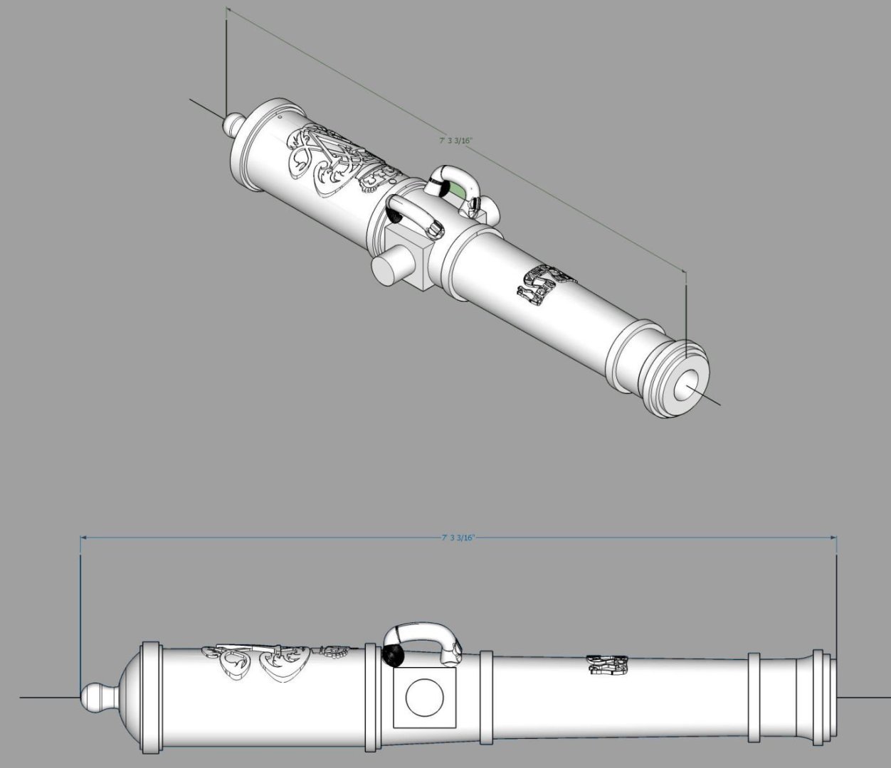
I am going to run a test print in 1/24th scale, this week to verify the file. If it prints OK, then it will be finished.
I can reuse the handle, scroll, and cypher files for the other cannon sizes. The Cypher though has 5 separate parts to make the whole! This allows me the have the various height levels.
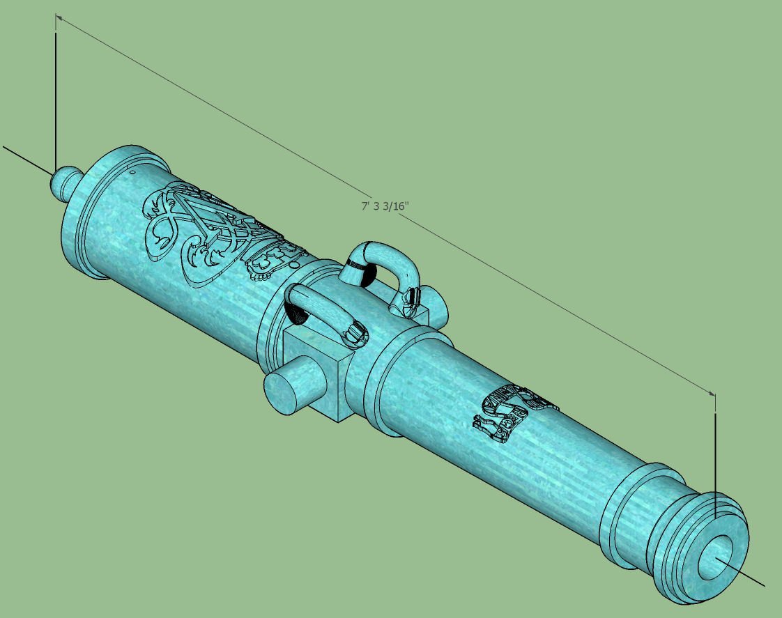
The following graphics show it in weathered bronze, or at least as close as SketchUp will allow.


- gjdale, Baker, scrubbyj427 and 3 others
-
6
-
Here are some shots of my latest project, a 1718 Pattern Spanish 12 Pounder. I just have to add a Latin scroll pattern to the barrel, that translates to very roughly "Don't mess with the King". The handles took me three weeks to create, with SketchUP. A little clunky, but most of the detail will disappear at our scales.


- chris watton, bruce d, druxey and 2 others
-
5
-
-
Sad news! My condolences to the family.
- hollowneck and Canute
-
1
-
 1
1
-
-
Spain won the legal battle, with no compensation to the people who spent funds searching for it. The ship, while a merchantman, carried cannons for defense, thus Spain argued that an armed ship is a warship, and won.
- Ferrus Manus, modeller_masa and mtaylor
-
1
-
 1
1
-
1
-
P.S. Clever Models has a handful of free downloads, if you wish to see examples.
- Egilman, Old Collingwood, Jack12477 and 2 others
-
5


3D Printing Cannons in Resin
in 3D-Printing and Laser-Cutting.
Posted
I went htrough the Fredrick cannon specifications I found online, and determined that once a specific size cannon was drawn, say one length of 6 Pounder, the diameters of the various sections of the other 6 Pounders were all the same. The lengths of the sections (First Reinforce, Second Reinforce, etc.) were then changed to a fixed proportion of the barrel length. I am in the process of drawing the "missing" cannon lengths for the Fredricks. If anyone can verify the available sizes of the Armstrongs, I will fill those in also.
The diameters were also not directly proportional between say a 42 Pounder and a 12 Pounder, there were "Fudge Factors" for some of them. For example the specification for one diameter is listed as 36 units for all cannon sizes in the text, but then a chart is provided that gives a different number of units for that value, depending on the Poundage of the cannon. For example the units for the 42 Pounder is 32 rather than 36, for that value.
I will be going through all the cannon sizes and checking the drawings against this spec, and getting them as close to this spec as reasonably possible.