


thibaultron
-
Posts
2,876 -
Joined
-
Last visited
Content Type
Profiles
Forums
Gallery
Events
Posts posted by thibaultron
-
-
-
Yes, I'm using SketchUp. I have an old loaded on the computer version. Because it is so old, I have been locked out of being able to load any of the extensions. So I am being very careful to not mess up my system drive, as I can no longer reload what I have. I'm thinking of going to either the subscription versions of either SketchUp or Fusion. Hate to spend the money though.
-
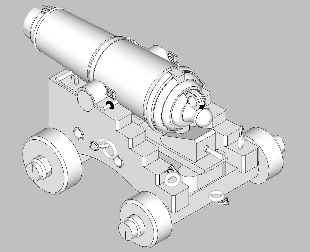
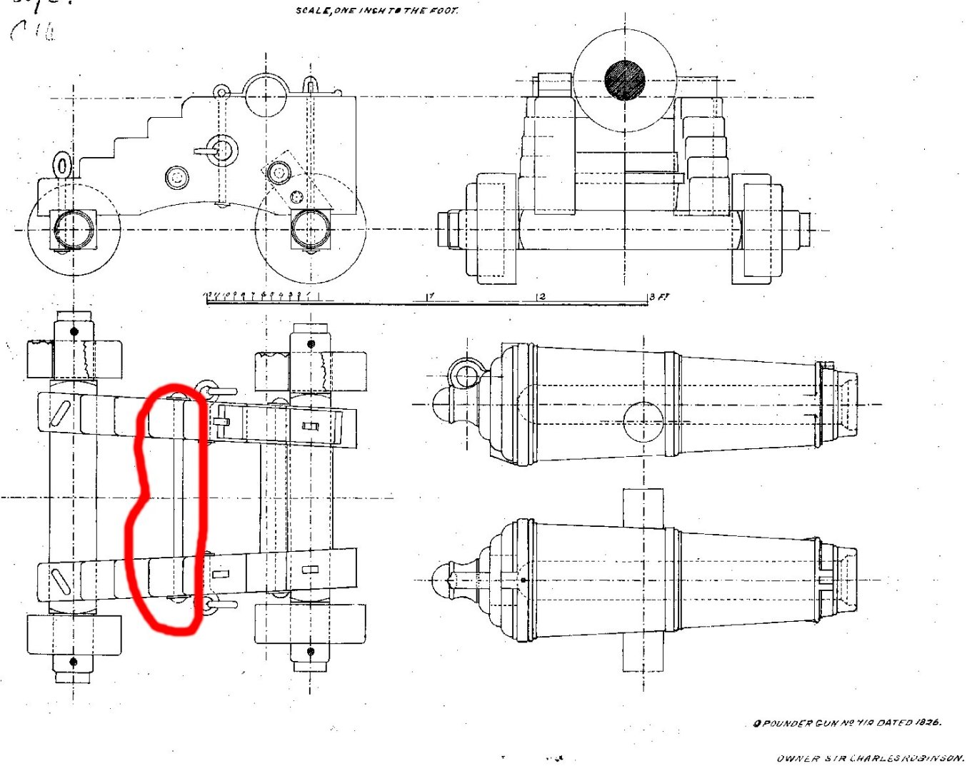
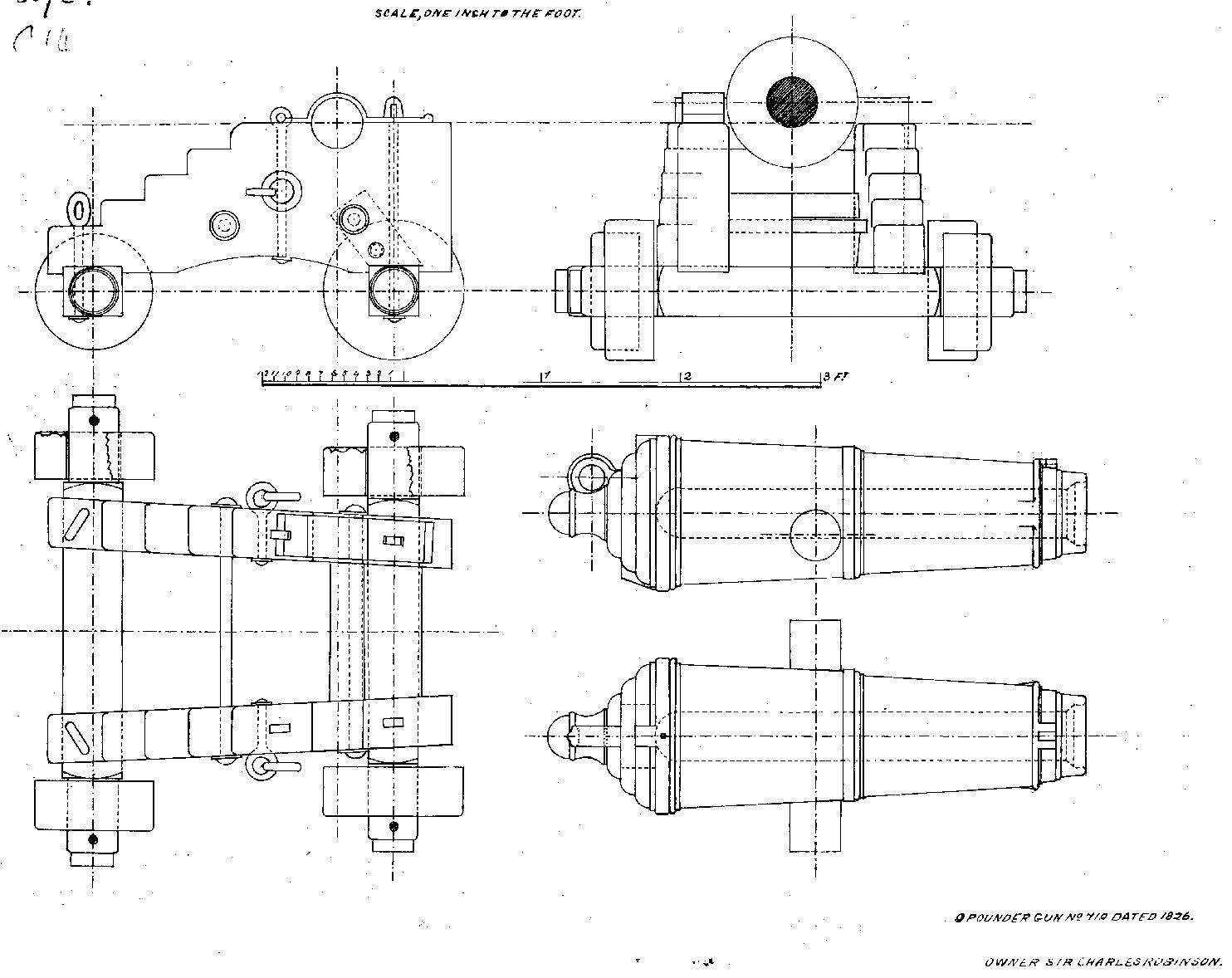
When I drew the Carronade with trunnions, I showed a few posts back, I used a drawing from 1826 to make it from.

Well, I decided to try my hand at generating the carriage shown for it in the drawing. This drawing does not show the parts used to elevate the barrel. The Stool Bed, and the Quoin. I went through my library, and found drawings for a 32 Pounder in the Anatomy Of The Ship book on HMS Pandora. I rescaled the carriage drawings, and found the rescaled drawings to be quite close a match in length and height to fit the 9 Pounder (the carriage was wider rescaled, but a little math got me a scaled width for the parts). I used the drawings for the two parts as a basis for new ones. I also added eyes to the front and back of the carriage, as shown in the Pandora drawings.
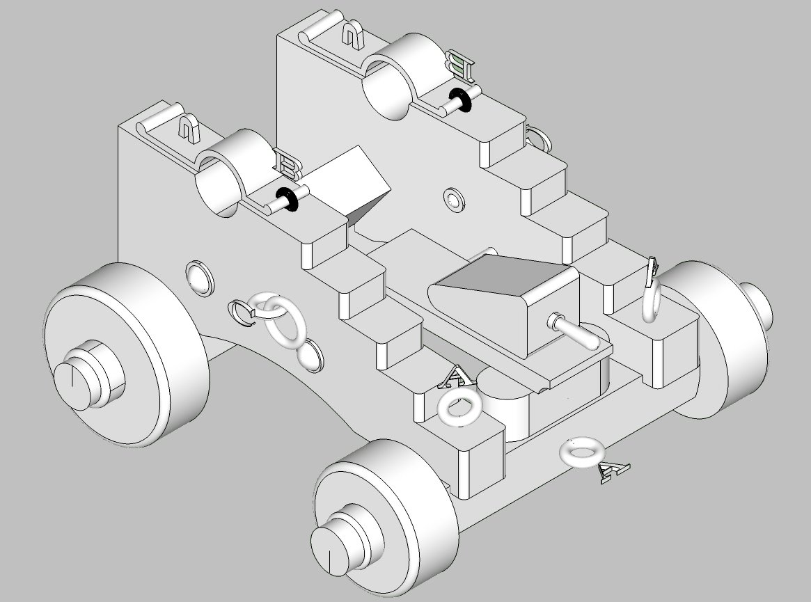
Here are a graphics of the carriage with and without the 9 pounder barrel. I still have to add locating holes and pins to the 3D drawing, before I generate the final 3D print files. I'll post them in a few days. The letters refer to wire eyelets that the modeler will have to make, I'll include drawings for them too. 3D printing them would be a nightmare, and the resin parts would be quite fragile. The modeler would also have to make the brass rings that hold the trucks to the axles.
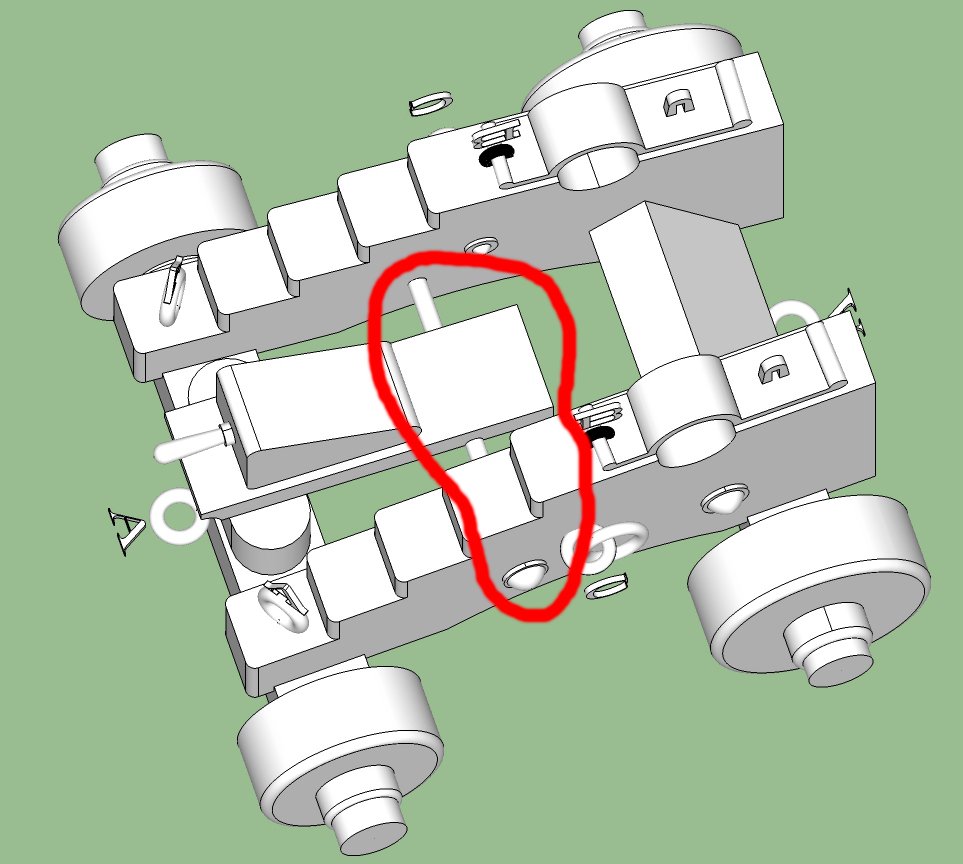
I'm going to have all the major parts as separate pieces, thus the need for locating pins. The Cap Squares (pieces that holds the cannon to the carriage have to be separate anyway to allow for the cannon to be installed). Should I, also, have an assembled (except for the cap squares, and truck rings) version? There is a through "bolt" that the front of the stool bed rests on that would be hard to print, in place, especially in smaller scales.
-
-
Anime, yes, "Kiki's Delivery Service"
- Egilman, BLACK VIKING, Canute and 3 others
-
 6
6
-
-
Fantastic work! One thing you might consider is carving out the edge of a plank to show one of each type of tenon in place, just for everyone to see the complete construction methods employed.
- mtaylor, Hubac's Historian, tarbrush and 1 other
-
4
-
When I CADed cannons, I started with 48 surfaces on a round part. For anything 1/48th or smaller, this was fine. at 1/24th faint coarseness could be seen, if you looked closely. This was with a resin printer, at 35um layer heigth printed at 45 deg.. You did have to look closely though. I drew the rest of the 3D files at 72 facets, and no problems were seen. With a filament printer, I have no idea, as I don't have access to one.,
-
-
I think a 1/48th scale of the Shallop would be great!
- Nirvana, dunnock, chris watton and 2 others
-
5
-
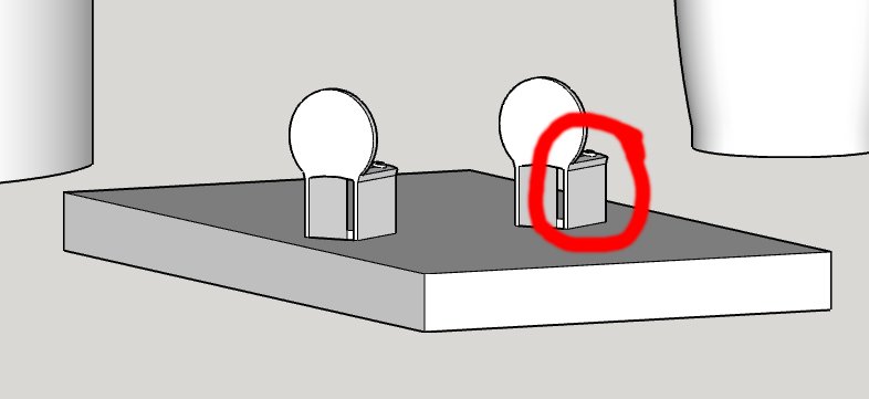
As the parts are so small. you might want to have a solid base with the parts then supported by sacrificial standoffs. This makes it easier to remove them without risking separating them from a larger support. I did this for two small step plates for a HO scale tender bunker I designed.
The graphic below shows this with thin walls going from the base to the curved base (horizontal in this view) that the step is mounted to. One of the support walls is circled in red.
-
I have cats, case! I have an "in" for this preference, though. I have two large glass display cases I got free, one 5 feet long and 6 feet high, the other 6 feet long and the same height. I got these on a fluke of good luck. I also have a 5 foot long store counter cabinet that I bought when a thrift store was remodeling, another instance of being there at the right time!
-
That's a very small scale! The only thing I can think of is to print them vertically with the barrels farthest from the build plate, and the widest part toward the bottom. There is not enough of the smaller guns to tell me what they are supposed to look like.
Also have him cut back on the cure time, long cure times can warp thin parts. Playing with the exposure times might help.
-
-
-
On Ebay, you can save a search, and they will send you an Email when the subject is listed. I wanted a certain model of a railroad station, that had a limited run. It took a couple of years but a kit was finally listed. I paid too much for it, but not an unreasonable amount.
-
The siding looks great, don';t hide it under paint! By the way say "Hi" to your neighbor for me!
-
-
7 hours ago, DARIVS ARCHITECTVS said:
Hi Allen! Only two single blocks? Oh well. I just rigged almost 100 of the guns on three decks with a single and double blocks for the gun tackles. Knowing that earlier would have save me a lot of work!
") A fellow ship modeler (Szkutnik on the SoS forum) made 3-D models of the barrels and printed them out for me. They are detailed enough to have the touch hole and emblem on top recognizable as John Browne's work specific to the Sovereign of the Seas.
A fellow ship modeler (Szkutnik on the SoS forum) made 3-D models of the barrels and printed them out for me. They are detailed enough to have the touch hole and emblem on top recognizable as John Browne's work specific to the Sovereign of the Seas.
The STL files for the Brown Pattern Canons are available on the NRG web site.
-
-
-
Carronade Files
Note: that they were Zipped using PeaZip, some other unzip programs give strange file extensions when used to unzipp the files.
Carronade 1796-1815 Graphics.zip
Length Chart Of Full Sized and Scaled Cannons_002 with Carronades.xlsx
- myMADNESS78, Seventynet, mtaylor and 2 others
-
5
-
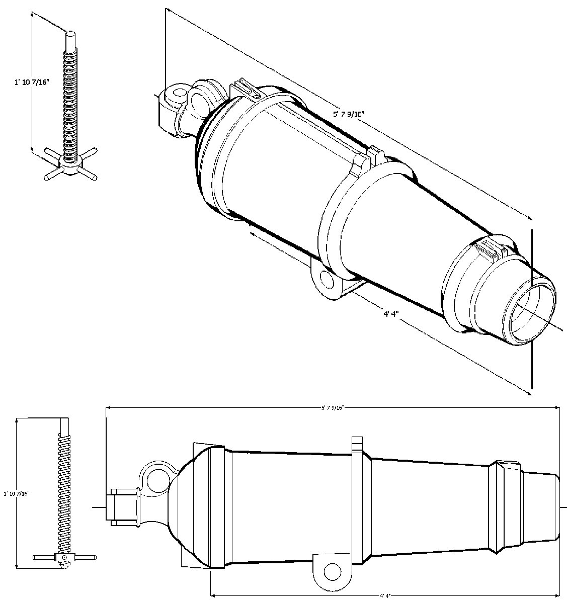
After I sent the files to the NRG, which they have added to the Resource section, I drew a set of Carronades. They have the files, but have not yet had a chance to add them. So, I'm adding them to the thread, in case someone needs them now. I'm also adding a new spreadsheet that has these added to the data. Here is a graphic of the 42 Pounder. The set includes 12, 18, 24, 32, and 42 Pounders. The STL files include a separate leveling screw. This allows you to adjust the cannon angle. The screws are over-long. They should be cut so a couple of inches sticks out when the cannon is horizontal on the carriage/slide. The screw top should be rounded.

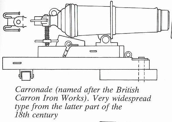
This graphic shows a drawing of a similar type, with the length of the screw depicted.
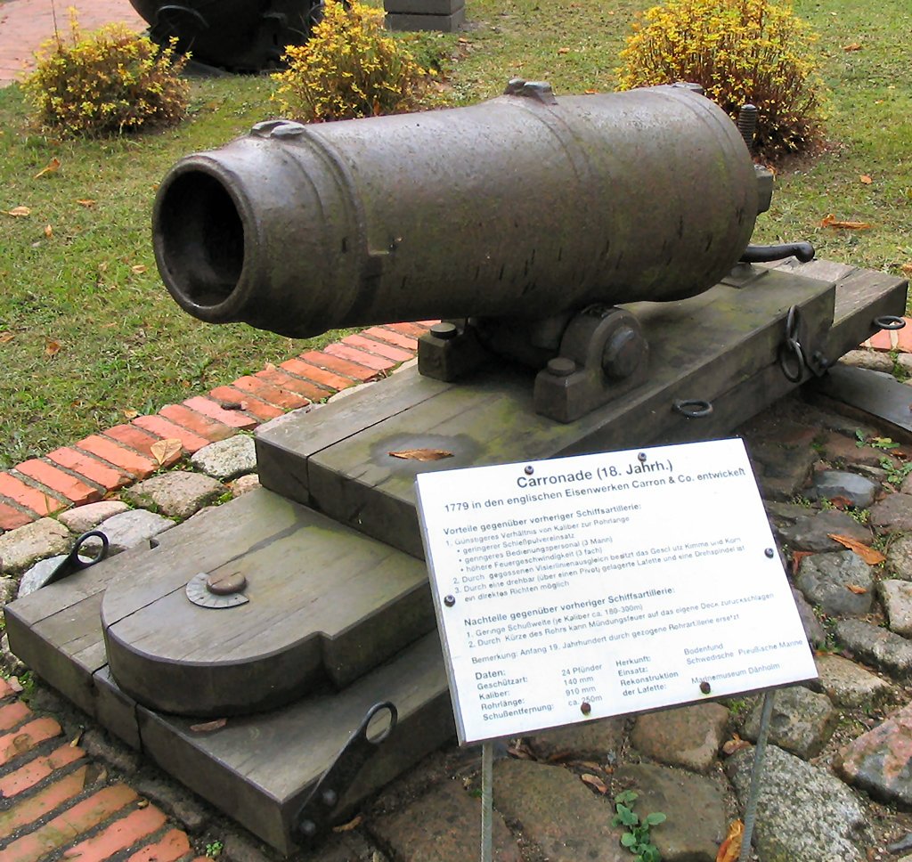
Here is a photo of similar cannon. If you look at the right hand edge, you can just see the rounded top of the screw.
The next posts will be the files.
-


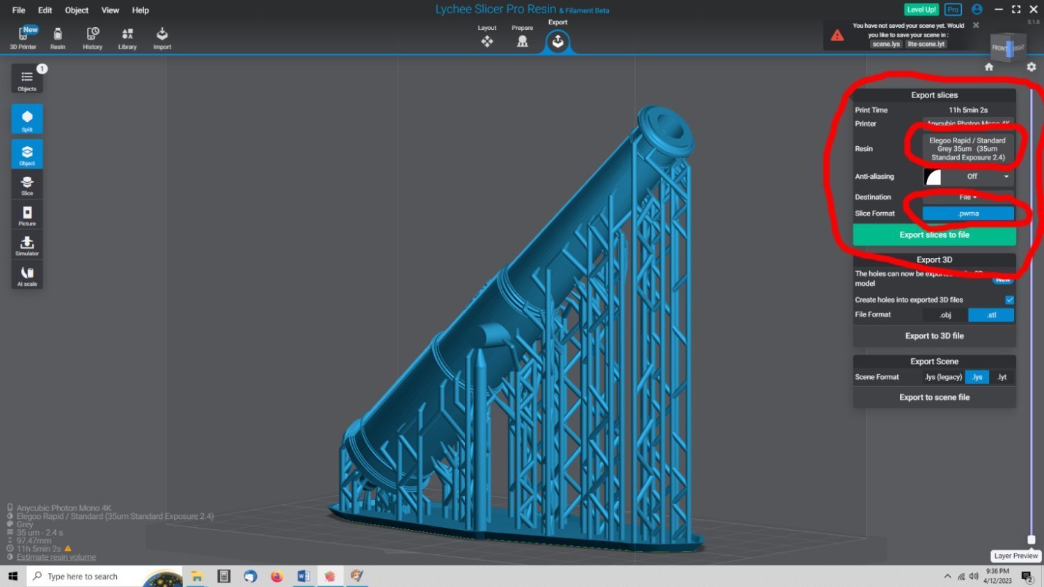

3D Printing Cannons in Resin
in 3D-Printing and Laser-Cutting.
Posted
Got the locating pins in place. I now have to go through all the parts and validate the STL files. Then write up a PDF on assembling the carriage, and make the 2D drawings for the fabricated parts.
Here is the exploded diagram of the parts. There are two sets of caps. The first (left hand set) has the hinge eyelet as part of the part, this simplifies the building of the carriage. The second (right hand set) has just an opening to use when fabricating the hinge eyelet separately.