jonny.amy
-
Posts
346 -
Joined
-
Last visited
Content Type
Profiles
Forums
Gallery
Events
Everything posted by jonny.amy
-
 I can't help it! I've always fancied building one of these... I just can't get the boss to get on board!
- 56 replies
-
- 3
-

-
- sd-14 cargo ship
- card
- (and 1 more)
-
Hi Kevin, Are you still building the SD14? If so, can we have some updates please? Cheers Jon
- 56 replies
-
- 2
-
-
- sd-14 cargo ship
- card
- (and 1 more)
-
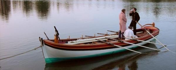
Keith, I think the tension of the outhaul / lack of outhaul in the aforementioned pictures could be based on three aspects: 1 - In Photo 3 - lack of tension is because of the use of cruising sails (a lot of these yachts will own multiple suits of sails, at least 1 set for cruising and deliveries, and possibly 2 or more sets for racing in various wind conditions), these would be a synthetic canvas material for longevity and robustness (last thing you want to do is rip the canvas sails with charter guests aboard), and would probably be cut to give ample shape to the sail for a short handed delivery crew or charter crew to get the best boat speed. 2 - In Photo 5 - the outhaul is tied off to the cleat (top left corner of picture) and coiled away (also top left). This is probably due to the (again) the use of cruising sails? Tell me, are these pictures taken from a promotional charter website/video/photo gallery? I've done fair bit of charter work as crew, and the mantra for most boats is "keep it simple" - 90% of Charter guests are not interested in the sailing aspect of the charter (mostly the looking good one a good looking yacht thing), and the yacht will be sailed with a small crew (usually a Skipper, Bosun and 2 Mates), so sailing her needs to kept simple. 3 - In Photo 1 - Just because the sail is full, it doesn't mean you have to have an outhaul running all the time. Photo 1 shows two short lashings at the boom end-cap, which suggests to me that the crew have removed the outhaul in place of the lashing. The natural stretch in the rope lashing would allow for some ease of pressure, whilst retaining a constant pressure and curveture on the foot and luff of the sail. Again, I assume that these are candid cruising shots, so she isn't fully powered by up in all of her racing fit out (read any Supersail World magazine and that will highlight the fact that all of the yachts have a cruising and racing set up for their rigs). I'm sure Photo 2 also covers this use of lashings. I hope any of that helps, and I would suggest that the outhaul is a roving line that only comes out in full force when racing or on very long distance sailing. I would also speak with Fairlie Yachts on the Hamble River to see if the current rig is as per designed, or has been optimised for the current owners requirements. Its is also noteworthy that Fairlie did the restoration of Altair in 2004/2005... https://www.fairlieyachts.com/ Cheers, Jon
-
Keith, The line that runs under the boom and terminates at the winch is almost certainly the outhaul. This is the most logical place for the outhaul to be, and most of yachts I've sailed on have had the outhauls running through or along the boom to a clam cleat or jammer, and then on to a winch at the base of the mast. The outhaul terminating on a captive winch on the mast allows for crew to make small or large adjustments to the tension in the sail when required whilst keeping the pressure in the sail (which in turn keeps the yacht on course), and keeps weight in the center or slightly off-center (to windward) when adjusting the sail tension. The picture shows a crew member adjusting the outhaul, and a crew member on the winch to grind the winch. As far as I'm aware Altair is one of only a few classic yachts that still use the classic canvas sail material and not the modern equivalent that has a lot less stretch in it when under pressure. The crew will be adjusting the outhaul to match the wind speed and pressure (in this case its a light breeze) so they can gain the correct shape in the sail. To help with sail shape, on modern racing yachts, a tweaker block is set up with the main sheet. I'd hazard a guess at the two lines in question attached to the underside of the boom are tweaker lines for fine tuning of the main. It would allow for additional twist in the sail when heading to windward and would eek a few additional fractions of a knot on that tack. In this example, by bringing the leeward (in this case, port) tweaker line done by a few inches you could add significant twist to the sail and increase their boat speed. Likewise, in the event of a large gust or squall hitting the yacht whilst hard pressed to windward (likelihood is that the yacht is trying to fetch to the windward mark in one tack), by easing the tweaker line on leeward side would dump about 40% of the power from the sail, meaning you avoid being hard pressed and potentially rounding up. The tweaker lines are mostly used whilst sailing upwind or reaching, but can be used to achieve finite adjustment of the sail whilst sailing downwind. Just my two cents, but it seems logical that it would be a tweaker. Cheers Jon
-
Gaetan, First of all, I'd like to say that this is an amazing project, and the scale you've chosen is very admirable! I'd love to have the space to build a 74, let alone a 74 at 1:24!! I've been watching this build log with awe and a slight bout of the "green eyed monster"! I build and paint in the lounge/diner of my 1 bedroom flat, so I'm used to working with the tv on in the background. I find I can focus better with the background noise because I'm consciously blocking out the noise (this has been described by the Admiral as "Boat Brain"). I find music is too distracting as I tend to hum or sing along and then break focus. Anyway, well done with this AMAZING build, and I can not wait to see the 74 progress further. Cheers Jonny
-
Coverage question?
jonny.amy replied to vossy's topic in Painting, finishing and weathering products and techniques
Hi Chris, My experience with airbrushing is limited (I am relatively new to the whole airbrushing thing), but the area of paint applied will be directly dependant on whether or not you thin the paint. I'd suggest reading around and finding out the best thinning ratios for the paint that you are using and then buy an extra pot of the paint to test your thinning ratios. I've been thinning Gloss White with 2 drops of White to 8 drops of thinner. This makes a very wet paint that is applied, but dries very quickly and then can be re-coated fairly soon afterwards. If you buy a cheap plastic model (best to work on something similar to your final project) you can see how the mix ratios then react with rounded surfaces such as the tumblehome of a hull. Cheers, Jonny -
Clare, I started HMS Wolf back in March and have been working on it as a sideline project. I didn't start a build log because I've been fairly busy developing a comprehensive 3D CAD model of my Grandfathers yacht to 3D print and present to him on his 80th Birthday. I've managed to get the hull of Wolf to a reasonable level of completion, but as it's my first paper kit, I've probably made avoidable mistakes on the kit. I'm considering bashing the kit even further by 3D printing a number of item such as the 3 lb guns and 1/2 lb swivel guns. As for Victory, I recieved the paper kit for my Birthday in July, and was surprised to find that not a piece of card was supplied with the kit to build up the "skeleton" so all I've managed to do on Victory is cut out the main spine and roughly cut out bulkheads 1 to 5 & 16 having glued them to 1mm thick Artist Mount. I have another 19 bulkheads to cut out, and then the intermediate/lateral support and deck pieces. So there is a lot of ground work to do before starting a build log in full force. Once I have the yacht off the desk I'll start a build log for Wolf and Victory. Cheers Jonny
-
Clare, I'll tag along too!! I'm building HMS Wolf and HMS Victory (both paper rather than card) at the moment - must say I'm quite infatuated with these kits! They're very fun and quick to build! I'm thinking of buying Mercury too, but will have to wait a while I think. Cheers Jonny
-
I think I would also like to see a POF model of e.g. a British or French 6th Rate in a reasonable scale (1/64 or 1/48) available to buy in 3 "Modules": Bow, Midships and Stern. I'd suggest each section be similar in size and each module could be bought for sub $200, so that the work could be phased and planned to suit building a model of reasonable size. That way one could build a 28 gun Frigate without the masses of space required (for example a dedicated room/garage/hobby shop) and tools to build a a full POF model. This would also allow each model to be sold by the manufacturer individually or as a bundle with a slight reduction in price, for example $200 each or $550 for "Modules A, B, & C". Just a thought....
-
I'd like to suggest a more obscure type of vessel - this is a Merchant Brig circa 1795 bought in to the Royal Navy to test Centerboards / Drop Keels on larger vessels. This design was developed and investigated by John Schank. http://collections.rmg.co.uk/collections/objects/66542.html The National Maritime Museum says: "Schank entered the navy at a young age, and was known for his skill in ship construction and mechanical design. While he was a lieutenant in 1776 he was in charge of assembling ships to battle the American Revolutionaries on Lake Champlain. He constructed HMS 'Inflexible', which he also commanded as part of a fleet that defeated General Benedict Arnold's fleet in October 1776. He was made a captain in 1783, and bought his design for ships with sliding keels before the Admiralty, which was incorporated by the Admiralty into ships. In 1821 Schank attained the rank of admiral of the blue". Scale: 1/64th to 1/32nd Size: Max. 800mm Period: 1750-1900's. Nationality: Don't care Building method: POB or POF: POF preferred if laser cut (consider POF method used for Longboat and Pinnace as 'easier' introduction to POF building??). Materials: Basswood / Lime - not Walnut (unless it has a very fine/even grain) Cost: sub $500 inc. shipping to mainland UK/Europe.
-
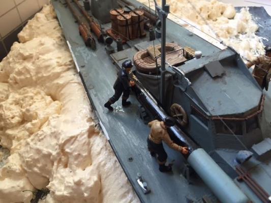
I have used this technique to paint the figures for my latest build, the Italeri MTB 74 (scale 1:35), and am happy to say that it works wonders. The Citadel washes (such as Nuln Oil) are water based, so can be watered down to cater for a lighter wash on the faces and hand. Thanks Chris for posting this. Cheers, Jonny
-
Sea Stand/Diorama
jonny.amy replied to felelo's topic in Painting, finishing and weathering products and techniques
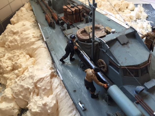
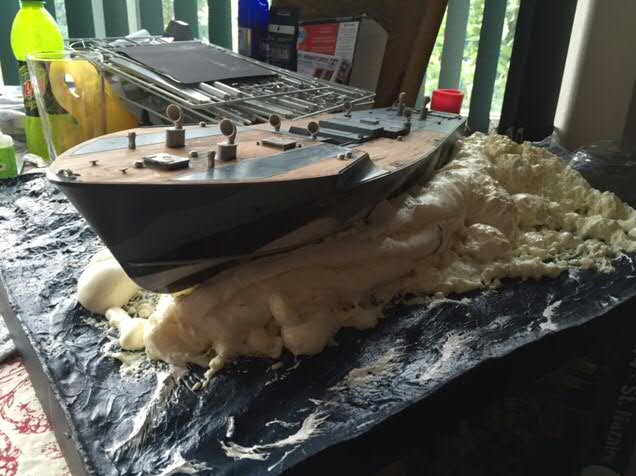
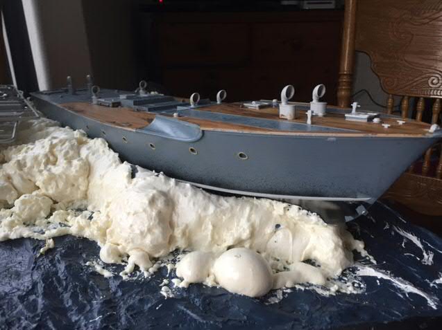
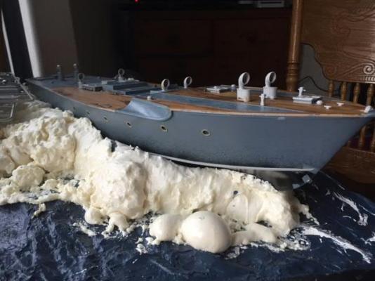
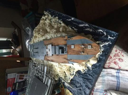
Felelo, I am building the Italeri MTB 74 kit as a waterline model. I had previous built up a base for an Airfix HMS Victory build that I binned off because it was completely terrible (I have no idea how a child/teenager is meant to build that kit, let alone an adult, without serious kit bashing). Anyway, I built up the base using six main "ingredients", an A2 sized artists field sketching board, 3 or 4 kilos of cheap porridge oats, two large bottles of thin CA glue, an A2 sized picture mounting card, auto-filler, and dry-clear caulking. Firstly, I drew the outline of the subject on to the artist board (10mm thick), and cut out 4 no. off 75mm thick strips of the mounting card to build up a frame. The card was PVA glued and nailed to artist board, making sure it was straight. Make sure you run a seam of PVA along the joint between the board and card. I reinforced the corners with some more of the mounting board. The joins were left under compression (clothes pegs work really well here) for about 6 hours. After the corners are dry, and most of the PVA beading is dry, wrap the hull of the model in clingfilm (or a plastic bag), when you have done this pour in all of the porridge oats. This will give you an easy wave making medium. Once happy with the "lay" of your waves, working in straight lines up and down the board, start applying the CA glue to the oats and stop about 25mm from the hull. The CA glue will soak through the oats and secure the bottom most layers of oats and stop any slips as you remove the hull. Remove the hull (keeping the clingfilm on the hull). Cover the rest of the base in the CA glue. Leave this overnight to really soak in. Next, you want to get a thin coat of auto-filler or DIY filler on top of your oats to give you a smoother water effect. Use an artists palette knife, it works wonders as you can flick the filler around a bit to make the water texture. Once happy, leave to dry overnight. Once dry, spray paint an "Ocean Blue" colour and once dry highlight with specks of white paint to add wave crests. Again, leave to dry. Cut the mounting board to match the profiles of the waves, and paint black. The last part for base is to add detailed "shimmery" waves with the dry-caulking. Applied in ta similar fashion to the filler with the palette knife, it looks especially good off the wave crests. Now, with my base I had built in accordance to the Victory hull, and seeing as this kit was too much trouble to continue with, I had to modify the base to fit the Motor Torpedo Boat hull. Seeing at the hull was double the size of Victory (Scale 1:180), I had to cut out some of the base. Bearing in mind that this is filler, and super-glued porridge oats, it's not the easiest thing to start butchering, but does come apart fairly cleanly. So now how did I modify this gaping hole to fit a new hull?! I used expanding foam, and a boat load of it. With the hull wrapped in more clingfilm, fill the cavity in the board with the expanding construction foam (do this outside as it is toxic to ingest - don't want pets or children accidentally doing that), making sure you have more at the stern than the bow as you want to have a huge bow wave on this bad boy!!! Simply weight the model down in whatever position it will be in, and leave until the foam has dried. With the hull weighted down, the foam will seep out of gaps between the hull and base, and create "white water" as the boat is going through the waves. These photos are of my display/diorama of MTB 74 en-route to the St. Nazaire Raid 28th March 1942. The expanding foam dries solid, but is still soft enough inside to be cut with a sharp knife to add more texture to it. It is also safe to paint. I hope this helps, and if you go down this route, feel free to PM me with any questions. Cheers, Jonny
-
Merry (belated) Christmas everyone... I've not had much time working on the Sherbourne case recently due to Christmas, my Victory window display, and the longboat, but I'll get on it soon. I currently have a puppy asleep on my lap, so there won't be any sawdust being made today, but I'm back to work on the 4th, so I still have plenty of time. I hope you all had a wonderful Christmas and that Santa or the Admirals got you all new kits and tools. Cheers, Jonny
- 188 replies
-
- 2
-
-
- Sherbourne
- Caldercraft
- (and 2 more)
-
Hi Chaps, Sorry there's been an absence from posting about the Longboat for a few weeks, but there has been myriad of thing's on my plate recently, and work has been very demanding, with a huge ramp up of progress prior to Christmas. I've also had my local hobby shop (mostly selling wargaming kits/tools/paints) contact me about producing a window display for their store. I've taken on said challenge, and have started building the Airfix HMS Victory (1:180) as a waterline model setting sails and firing a broadside. Ideally I need to get the model off the dining room table by the 22nd December to have a clear table for Christmas, this will be a bit of challenge as the kit is far from the standard I was expecting from Airfix. I will be making smaller updates to the Longboat as a break from Victory. Cheers, Jonny
-
Hi all, I received the display case sections on Tuesday for Sherbourne. Over the last 48 hours I've been building the side panels for the display case. It's going a lot better than my previous attempt, but I've found the glue I am using to glue the panels in place takes over 24 hours to dry properly, so progress is slow. I've also notice the backboard of the display has started to sag so will need bracing back until it is square again. I hope to make some headway tonight and tomorrow. Cheers Jonny
- 188 replies
-
- 2
-
-
- Sherbourne
- Caldercraft
- (and 2 more)
-
Hi Kevin, Your Bismark is looking great, and your Cocker is absolutely gorgeous. The Admiral and I have a 5 month old Working strain Cocker Spaniel. I think there's more springer in her than cocker because she is nuts, but very lovable. Be prepared to accept that time in the man cave and shipyard will dwindle very quickly over the next few months. This is my little pup, the dinosaur costume is courtesy of the Admiral, she thought it looked cute... Cheers Jonny

-
Mark, I recently found these Newline Design figures. I had forgotten to post about them yesterday. They look fantastic and the hands, heads, and feet all look to be at the right scale as well. I believe 28mm Scale is a very popular Wargamming Scale, and the figures I searched for in the past were of the "bulbous head, hands and feet" variety that personally I think would ruin any model.
-
Firstly, I'd suggest looking for a deck layout of a similar sized ship on the Royal Greenwich Museums website under the ship plans search engine. Secondly, crew members take some of the emphasis away from an empty deck, Perry Miniatures and Amati do some good 28mm tall figures that fit 1:64 well. Also, try building the gun equipment like the worm and sponge. That won't be easy to start off with but I'm sure you'll find a method eventually. Lastly, things like chicken coops, flag lockers and cannon shot storage can easily be made from wood scraps. Can you post a photo of the deck at it's current stage of construction so we can see what's missing?
-
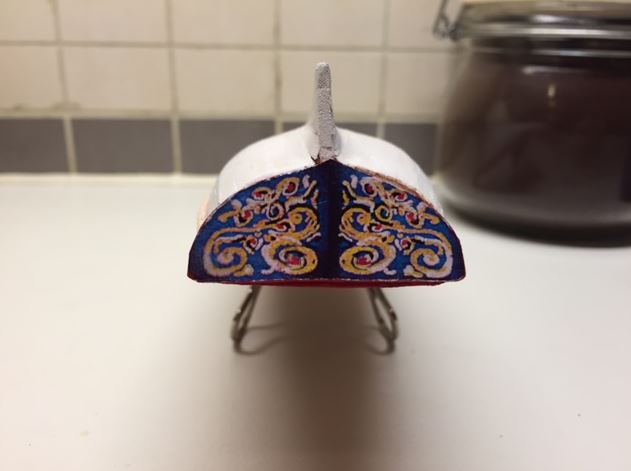
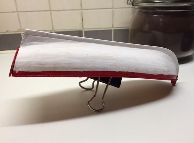
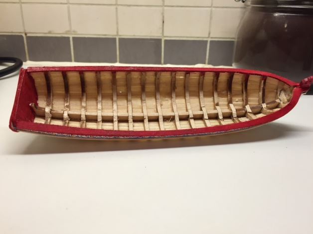
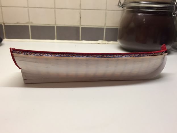
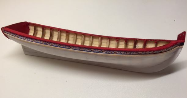
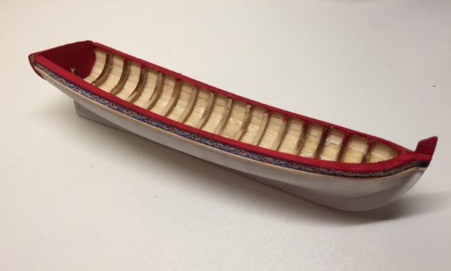
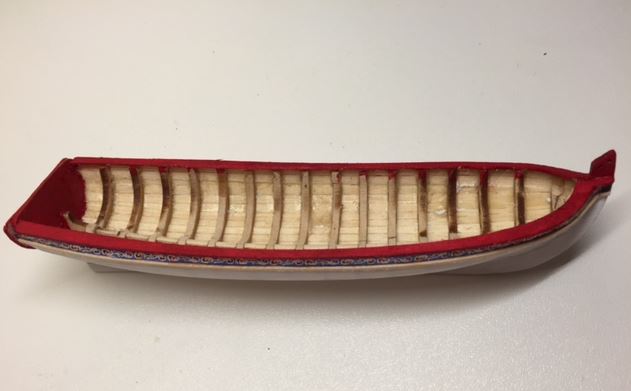
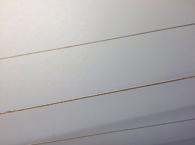
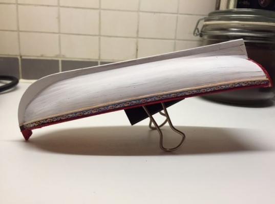
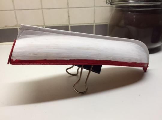
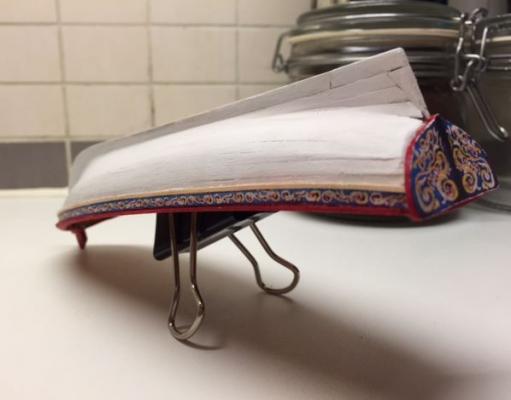
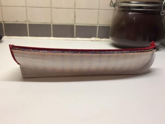
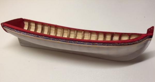
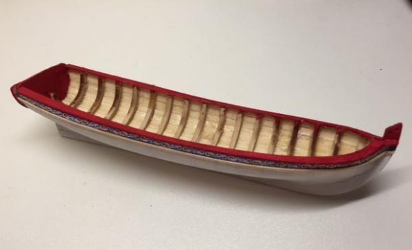
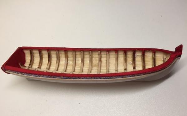
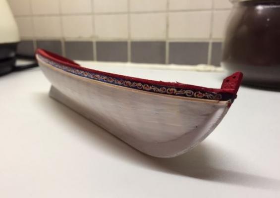
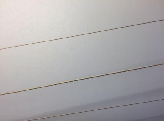
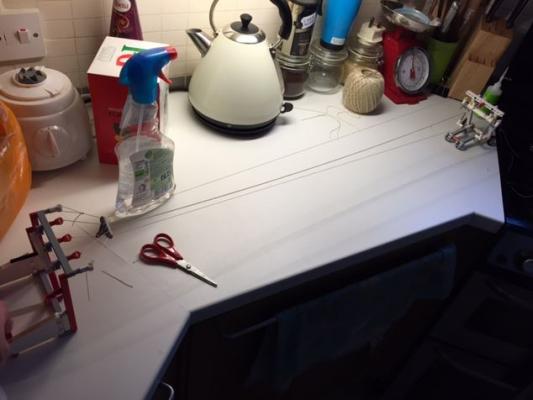
Hi Guys, Sorry the photo's haven't been published earlier, I was hoping to add another few of them to the collection last night, but spent the evening sanding out a water stain from the wood flooring in the entrance hall to our flat, and then walking the dog. So as for progress on the model, I've made a big jump ahead in the activities. I've finished the planking on both the Port and Starboard sides of the hull, broken out the inner parts of bulkheads, sanded them down, and have installed the caprails to the longboat. I have also managed to get some paint on to the model. I need to carry on sanding the inner faces of the caprails, and touch up the paint, but I'm getting there. I have applied the frieze to Stern by doubling up the transom. Although this isn't called for in the instructions, it was (to me) the most logical way of applying the frieze square and true. The hull has been painted off-white all the way up to the frieze as a nod towards the longboat of HMS Victory at Portsmouth Dockyard. Although the contemporary model at the National Maritime Museum shows the unpainted topsides (above the waterline and below the frieze), I decided not to follow suit, and try something a bit different. My reckoning is that all the topsides would have been painted to act as a means of waterproofing the planks. Although, I might be wrong. Please feel free to comment on this! As for the Lego brick Ropewalk, it works, but needs a rethink. Unfortunately the kit that I bought had no gears in it (I bought the kit in a catalogue store), so I had to work on basic mechanical principles. Here it is set up on the Kitchen work top. It's a bit jerky in operation, but makes rope. It is a two man job as one hand is required to turn the spindles and cranks and the other is required to keep tension on the fixed end. The moving end also requires turning to keep the tension in the rope. This is the outcome... I think it looks ok, but does not even compare to the stuff Chuck can produce. Cheers Jonny


-
Hi Chaps, I've been busy beavering away for the last couple of weeks on the 18th Century Longboat, and have got to a phase where she's really taking shape. I've managed to cut out all of the bulkhead centre's and I've added the capping rails to the model. I've applied the first coats of paint on the outer hull. I also reverted back to my childhood yesterday and built a crude ropewalk from Lego Bricks... It works, but requires a bit of tweaking to get it running smoothly. I might have to get the cordless drill involved in it too, as currently it is a two man job to keep tension and turn the rope. I'll post photo's later on of the ropewalk and the progress I have made on the longboat. Cheers for now, Jonny
-
Hi all, I have ordered some the pre-routed display case sections from CMB which should be arriving today. My first attempt at display case building wasn't the greatest effort. So from the lessons learnt from that, I've splashed out and bought the pre-fabricated sections that I can simply cut to length and glue together. The Admiral is out for the weekend, so I plan to utilise the free time for swilling coffee and building the display case. I'll post photo's when I get started. George - I had looked at the "Billy Ruffian" book on amazon and thought that would be a "nice to have" book. I didn't realise it went in to such a depth as listing all the crew members heights. I'll definitely have to buy that now as I'd love to build Bellerophon some day. Cheers, Jonny
- 188 replies
-
- 2
-
-
- Sherbourne
- Caldercraft
- (and 2 more)
-
George, With the Perry Miniatures, the figures have a circular base attached to their feet, this is very hard plastic, but can quite easily be cut off with a razor saw, clamping the figure in a vice. Sand the feet clean, paint the figure and glue them to the deck. Easy! I've just looked at Newline Designs and their figures look anatomically correct for a model in that scale. The problem (as you have highlighted) is that most suppliers of 28mm tall figures have overly large heads, hands, and feet. The problem with the Amati 25mm figures is that they look too small on a 1:64 model (although they are designed for 1:64 to 1:54). I think the decision on which size to buy should be based on visual inspection of a painted figure whilst on deck. I found it difficult to gauge the size of the unpainted figure. That sounds like a very interesting book, can you please post an Amazon link? I have found that the Perry figures (Battle of Waterloo 1815 Riflemen) are slightly too tall with their hats on (about 32mm with hats), but in the background of Sherbourne they look correct. Perry also sell American Civil War gun crews, which I think would look fairly good on a ship below decks. The plastic used is fairly malleable, so alterations are fairly easy. Hahaha yes it is, I would tie 5 ratlines, paint 1 figure, tie 5 ratlines, repeat! Cheers Jonny
- 188 replies
-
- 2
-
-
- Sherbourne
- Caldercraft
- (and 2 more)
-
Hi George, thanks for stopping by. The Amati figures are the 25mm tall figures, but really are a bit small. The Marines in the background are Perry Minitures 28mm Scale, Battle of Waterloo British Rifles. They are probably the correct scales for the model as a 6 foot tall man at 1:48 is 54mm tall, and 1:72 figures are 25mm tall, so my guessing is that the 28mm tall figures are the correct scale for 1:64. I'd suggest looking online for Perry Minitures, and seeing if you can find any farm workers, or peasants to go alongside the military personnel as the sailors. These proved to be as illusive as rocking horse ****, but I'm sure if enough effort is put in to it you can find some. I need to build a display case for the model, but that may have to be a job for next year now. Cheers Jonny
- 188 replies
-
- 2
-
-
- Sherbourne
- Caldercraft
- (and 2 more)
-
Hi guys, Busy day today outside of the shipyard. I've been baking my secret family recipe Christmas Cake (it needs 6 weeks of brandy AND rum soaking so has to be done this weekend), and boiling ham for dinner as well. I've also been cleaning carpets, lugging furniture, and generally tidying the house. Now the cake is in the oven for the next 4 hours, I'll be back in the shipyard making some well needed sawdust! Cheers, Jonny
-
How Realistic Can One Make Sails?
jonny.amy replied to Julie Mo's topic in Masting, rigging and sails
I furled the sails on my Sherbourne, but I found the lightest canvas curtain lining with the closest stitching I could find. The materials was already a creamy-white colour, but after 3 hours of soaking in a tray of "builders" tea (minus the milk), I left them to dry naturally. The sails were then built up in similar fashion to original sails, although I used a single panel for the sails and added the panels of cloth to double-up the material. As for getting shape to them, I looked in to this, and found that ordinary fabric glue does not stick to Clingfilm. So I tried shaping a block of Balsa wrapped in Clingfilm to act as a mould for the sail. The fabricated sail was then pinned to the balsa block and impregnated with a 50/50 mix of water and fabric glue. This seems to have worked to create a shaped sail, but does require a mould per sail. I hope this helps. Jonny