
HOLIDAY DONATION DRIVE - SUPPORT MSW - DO YOUR PART TO KEEP THIS GREAT FORUM GOING!
×
.JPG.ca33079f5815b861e67b9c2cccd37982.JPG)

Blue Ensign
-
Posts
4,564 -
Joined
-
Last visited
Content Type
Profiles
Forums
Gallery
Events
Everything posted by Blue Ensign
-
 Cheers Guys, Thanks Bob, and Michael, I’m pleased you like what you see. @ Glenn Thanks BE, that makes sense. I wasn’t thinking like a fisherman 😊 It’s nowt to do with me Glenn, a few weeks ago I’d never heard of a Fifie, but I’ve done a load of speed reading.😉 @ Richard – ask away no problem. To some extent it depends on the tightness of the bend, but I tend to use cold water for a few minutes only, and then use a hair dryer on max heat to fix the shape I formed. I don’t think Chuck even bothers with water, just bends by degrees and uses heat alone to fix the shape. Regards, B.E.
- 195 replies
-
- 3
-

-
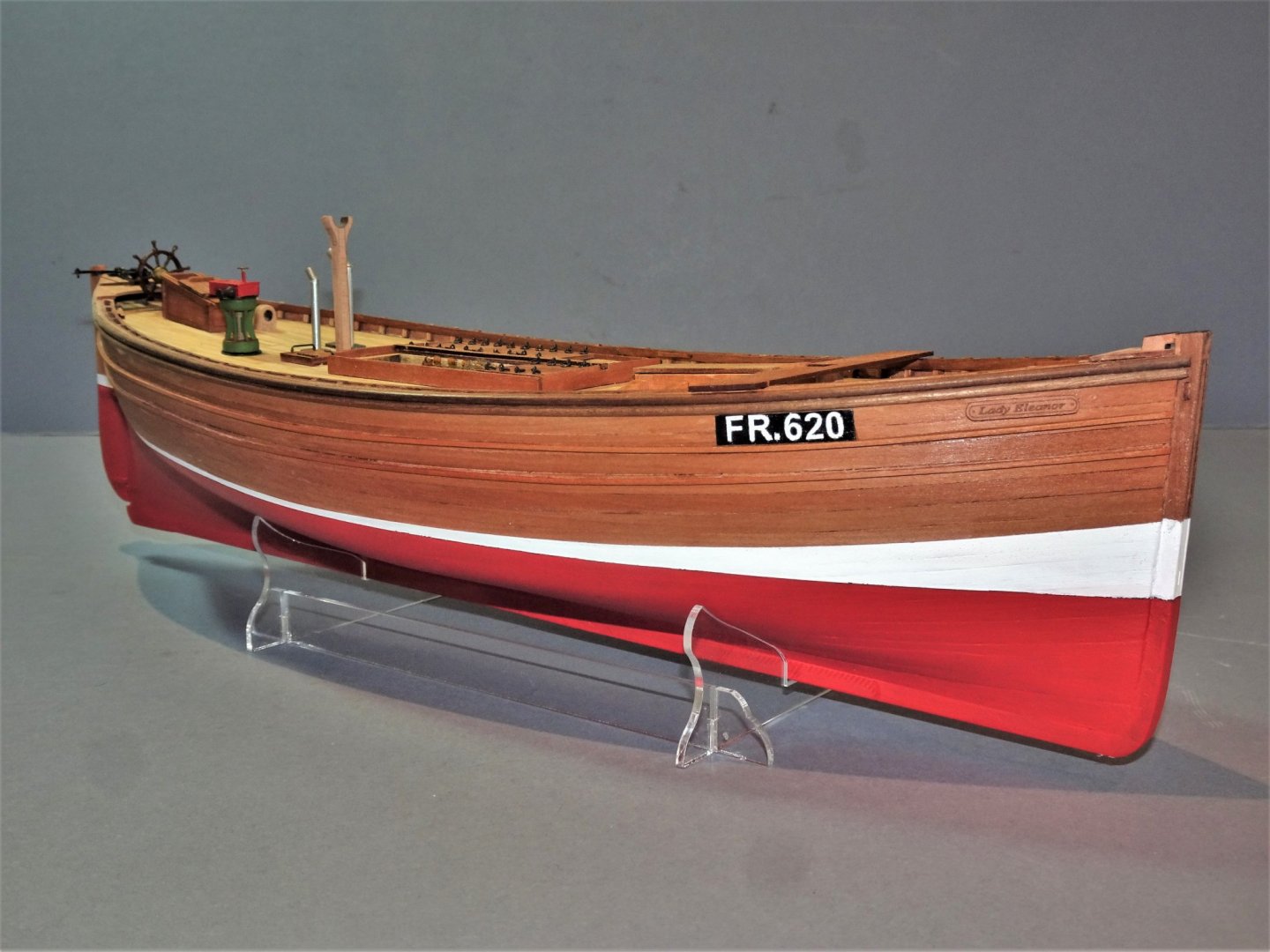
- lady eleanor
- vanguard models
- (and 1 more)
-
Wow Guys, a lot of questions. Glenn said Nice work on adding the nets. The location of the chimneys seems peculiar, seems like all the smoke would blow right in the helmsman’s face. I don’t think it would be an issue Glenn, the Capstan boiler and galley were not in use during the sailing of the boat. The capstan was used to set the large fore lug and hauling in the nets, when the boat was in drifting mode. The Galley would only be used once the nets had been cast. The only relative rest period for the crew was during the night whilst the boat was drifting. As I understand, once fishing began, the Foremast was lowered, the Mizen removed, and also the rudder, (I don’t know how) to prevent excessive movement. Chris said And I had (finally) my Zulu sail set order arrive today, so all that ordered sail sets for their Zulus will be receiving them within the next week, and anyone who now orders a Zulu and sail set can be shipped together. Nice work of the Fifie, BE, I see these models as a 'blank canvas' for the more experienced, who like to stamp their own mark on the kit. Thanks Chris, I very much look forward to building this iconic Fishing boat Richard Said There is one thing that sort of bothers me with the modification you have made to the wheel. Where does the helmsman stand. Normally he would want to face forward, behind the wheel. The mechanism would sort of prevent this & plus he would have to stand on the thwart (further from the boat's center of gravity, a bit more unstable). As you can see from the photo’s of the Reaper, Richard, there is not much room. The Skipper didn’t stand on the thwart he sat on it, to the starboard side. The port side was cut off by the Mizen boom. Some boats had a stool instead of a thwart. What did you make the nets from ? I used a soft Tulle net fabric, in the shade Peat Brown. It is cheap to buy, I got mine from a company called Minerva crafts, but there are a lot of online sales for this stuff. Are you going to add a fish smelling perfume to the open hatch ? I don’t think Mrs W would appreciate taking realism that far, Richard.😃 I've had to hold up on my Eleanor since I'm spending some unscheduled time in the hospital. As soon as I get put I'll be starting the 1st planking. Did you start in the middle for that and work towards the bow and stern and pin as you went along? Did you also soak the lime planks to get them to fit better? When pinning the planking I always start from the bow, but before that I have dry fitted the plank having tapered and shaped it where necessary using water and heat. Rusty Said Great workshop B.E. Really enjoying your build. I'm also interested in the Lady Isabella and may have to breakout the cc. Cheers, Rusty, I think there is a lot more detailed information on Zulu’s out there to assist a build. Bob said A chimney is easily made, from some 3mm ø aluminium tubing. Did you solder the aluminum chimneys? No, I just used ca to make the bond The nets are awesome! How did you make them? See my reply to Richard, above. I have the Lady Isabella and would like to find out more about these Zulu fishing vessels. Do you have any good resources that you could recommend? The good news about Zulu’s is that there is a lot of information on the net, including history, plans, excellent build photo’s, and historic photo’s. I have used the net extensively for my research, but I do have an excellent long out of print book – Sailing Drifters by Edgar J. March. Still in print is a useful book called Inshore Craft – Basil Greenhill & Julian Mannering. Doug said I was just gifted with a set of blueprints for the Zulu Muirneag. Plans were drawn by Harold Underhill in the 1950's. His book "Plan-on-Frame Models" has reduced version of three of the plans. I can't use the blueprint set so they're listed in Traders... One source of detail. Underhill’s plans are still available on the net at around £10 each. In relation to the Zulu kit there are some that would be more useful than others, eg; deck layout, rigging plan etc; B.E 02/07/20
- 195 replies
-
- 5
-
-
- lady eleanor
- vanguard models
- (and 1 more)
-
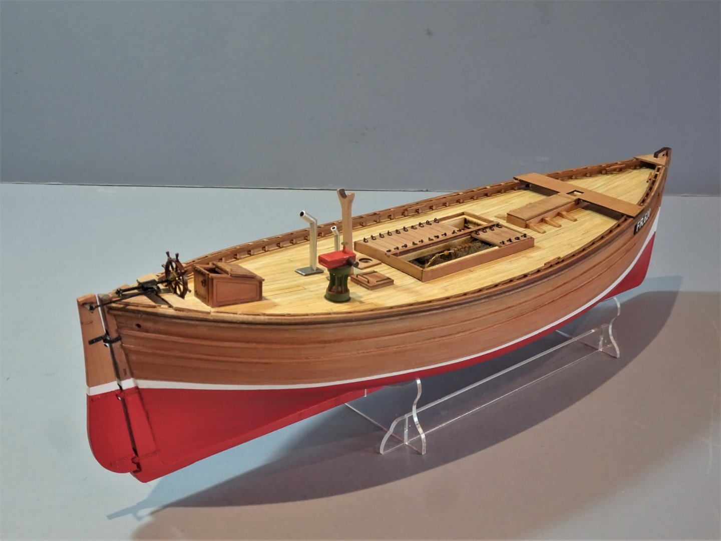
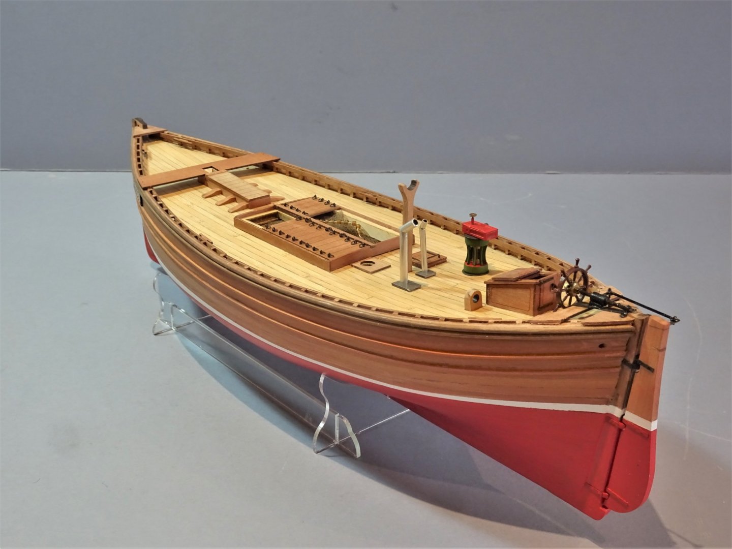
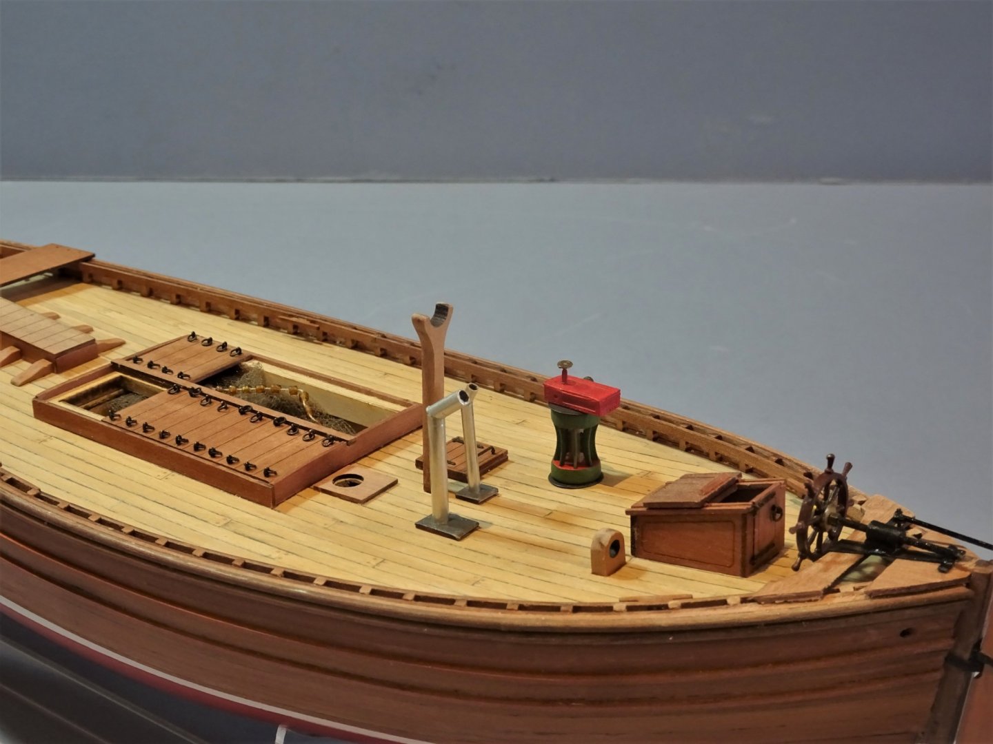
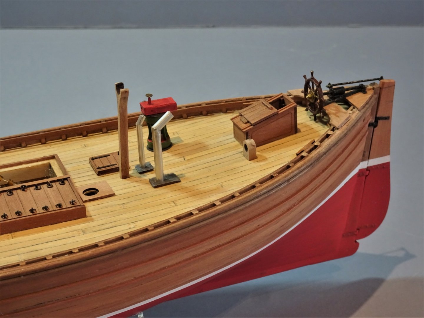
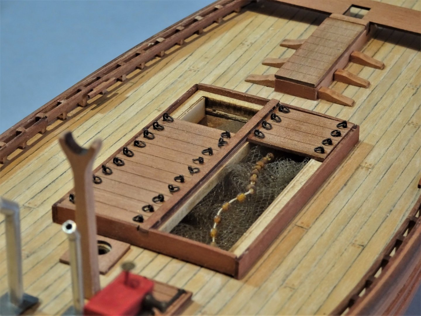
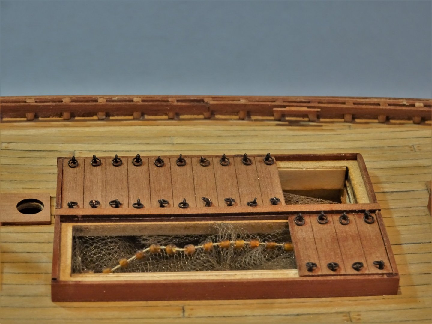
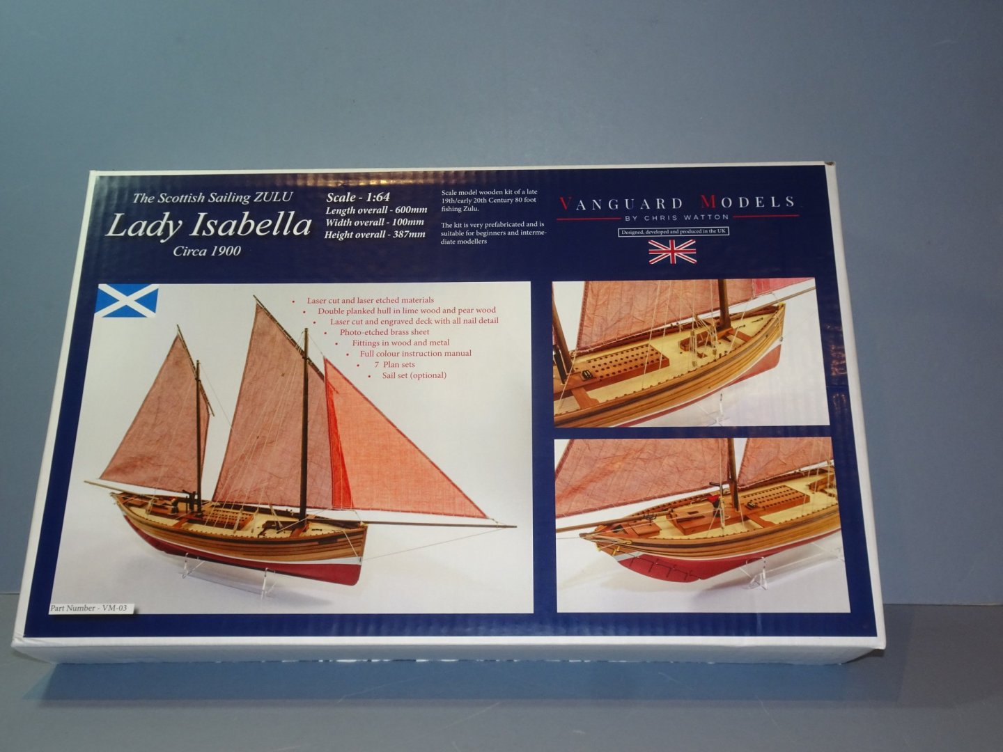
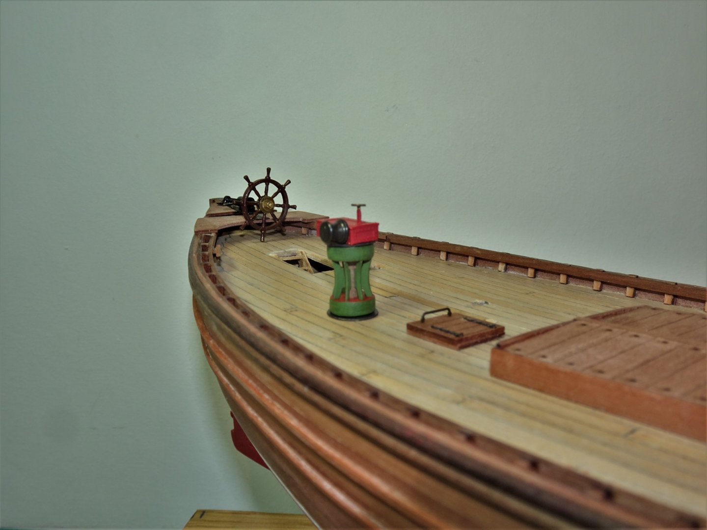
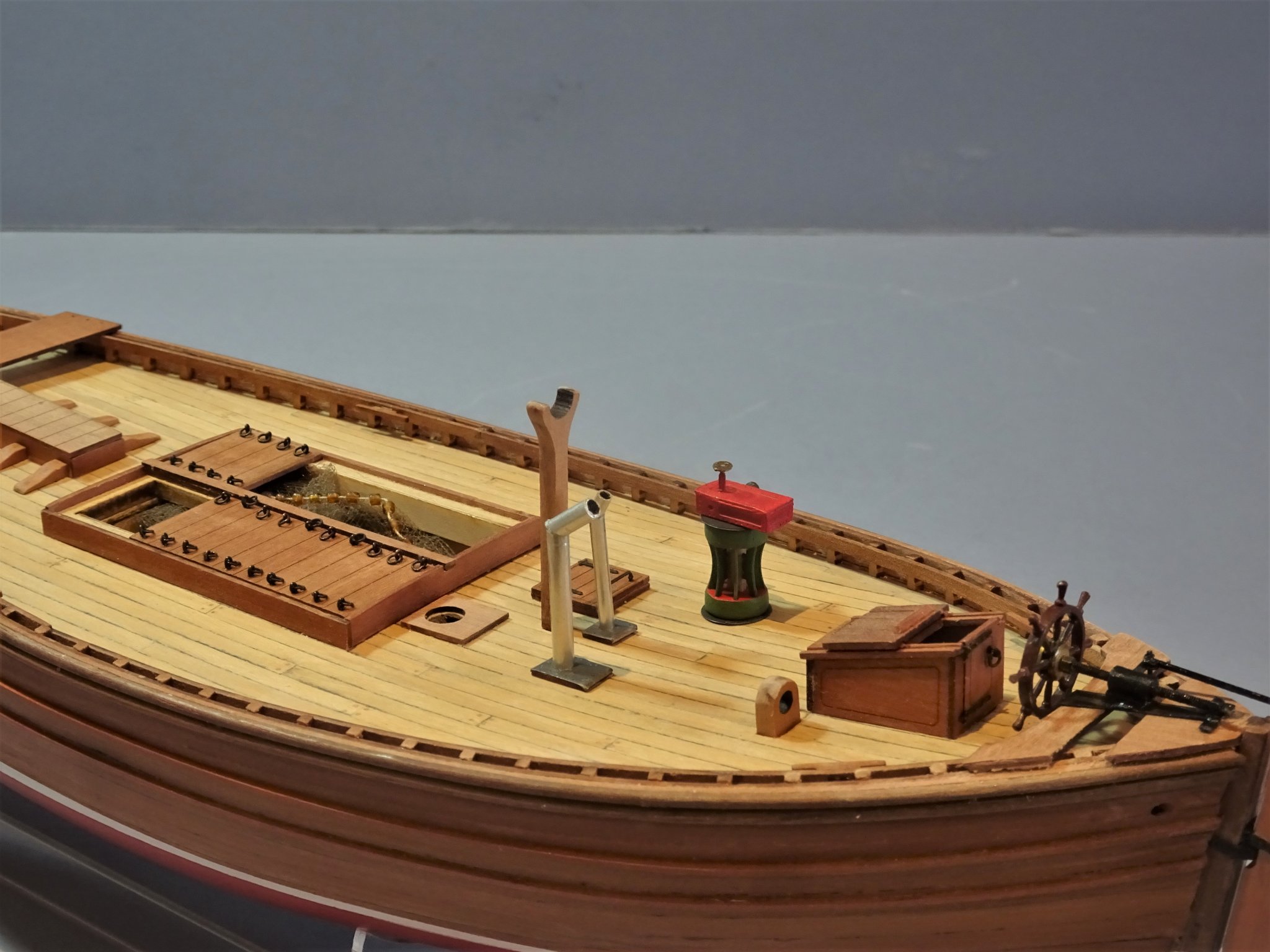
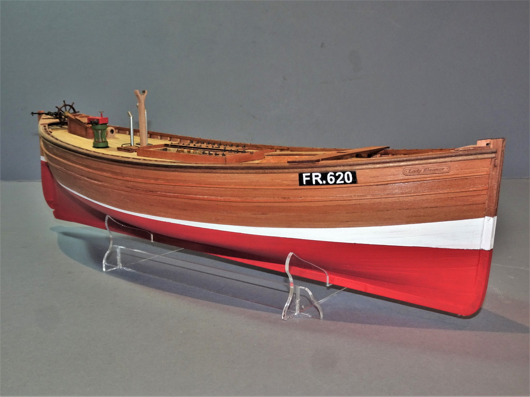
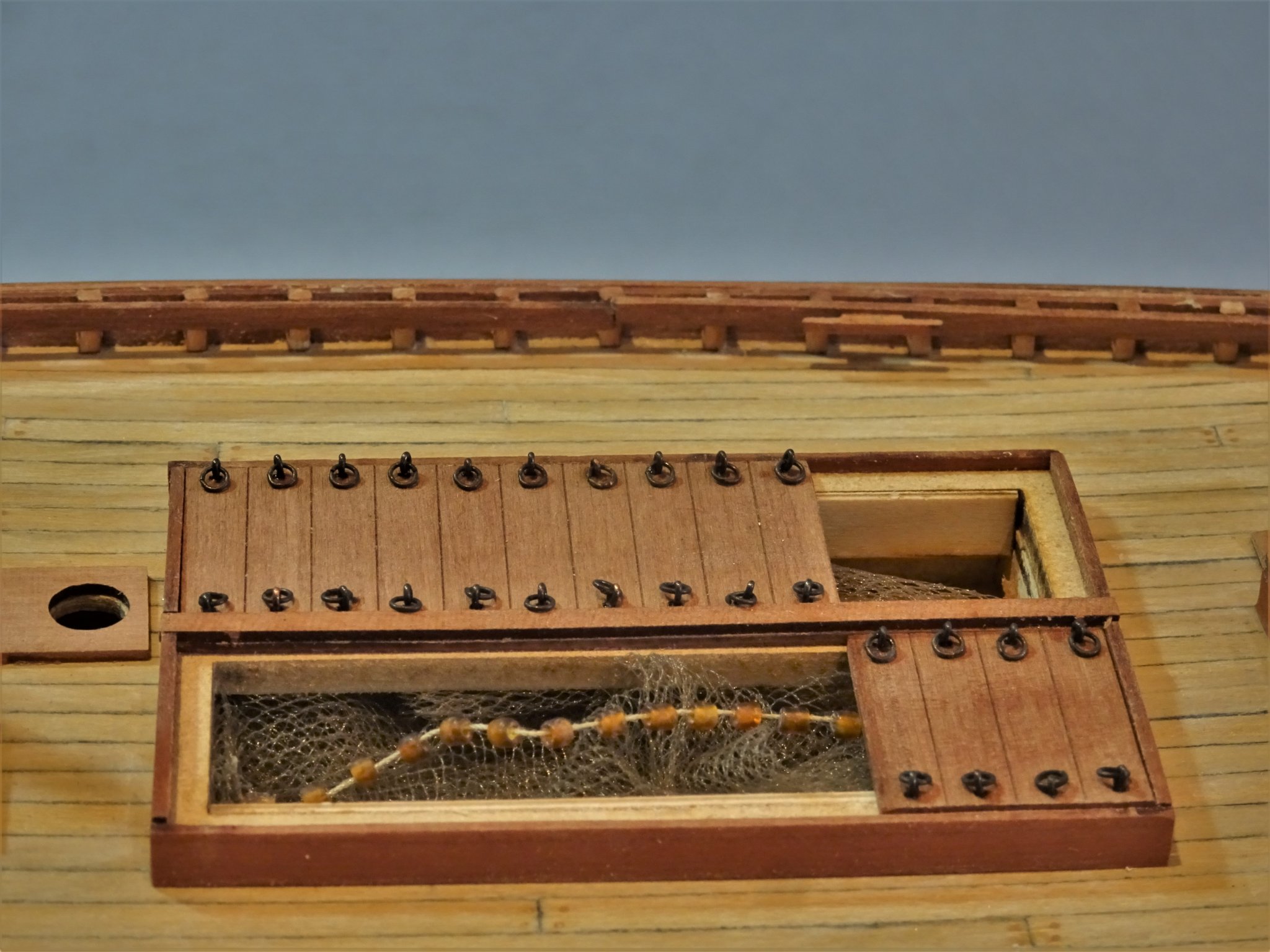
Thank you Grant and Bob, your interest is much appreciated. Post 21 Taking stock I felt this was a good point to review progress thus far. This is also a good point to set out the remaining deck fittings to ensure there are no unwanted surprises. 5825 I have made a couple of additions to the deck furniture, in the form of Chimneys, to service the steam capstan, and Galley stove. Such pipes are shown on the plans I have seen, and Reaper also has one. A chimney is easily made, from some 3mm ø aluminium tubing. A smaller second pipe was also fashioned for the galley stove. Because of my modifications to the steering I had to reposition the Mizen boom stop slightly. 5823 The cover boards for the Fish Hatch have been fitted with ring bolts in preference to the provided items, and only a portion of the cover boards are in place. 5839 The hatch is left partly open to reveal the nets that would usually be kept in that area. 5836 The nets were cast over the Starboard side and there should be a net roller running along the hatch coaming to assist the process. I don’t have sufficient detail of the arrangement to fit one yet, but I am looking. Such boats also carried seven 22’ sweeps stowed on the Foredeck and shipped into crutches socketed into the Timberheads. I don’t know if I will represent these at present. 5830(2) 5818(2) 5819 5822 5826 5829 Since I have started researching fishing boats I have been amazed at the sheer hard manual work, hazardous conditions, and danger involved in working these boats. The seamanship required to work the lugger rigs seems extraordinary given the harsh conditions they had to work in. It is hard to believe that contained within the hatch were some 60/70 nets, 60 yards long, and when strung together produced a drift extending some 3300 yards from the boat. The invention of the steam capstan must have been a very welcome addition to aid the exhausting process of hauling in the nets. So much am I enjoying this build, I couldn’t resist doing a follow up of the Zulu. 5843 Ordered yesterday, arrived this morning; great service Chris.👍 Shame to waste all the research I have done, and they will make a fine pair, but I won’t start the Zulu until the Fifie is completed. B.E. 01/07/20
.thumb.JPG.70065fb76a0931ccae57ee806152ab7a.JPG)

.thumb.JPG.4b0b3685a095b5087e9ae0999068fba6.JPG)
- 195 replies
-
- 17
-
-
- lady eleanor
- vanguard models
- (and 1 more)
-
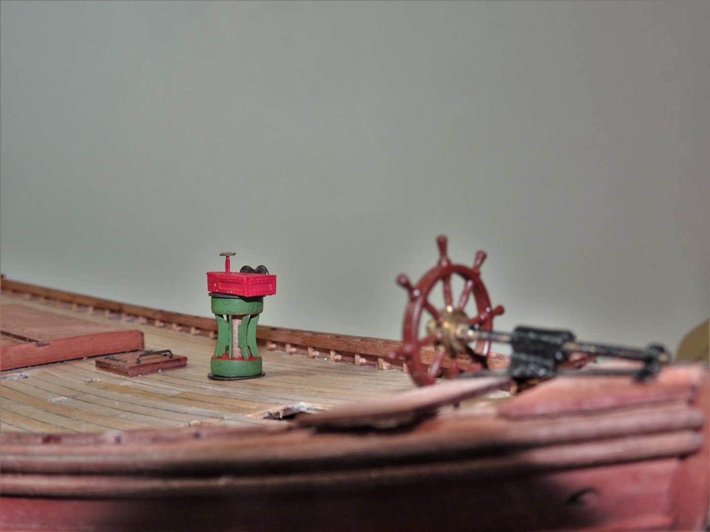
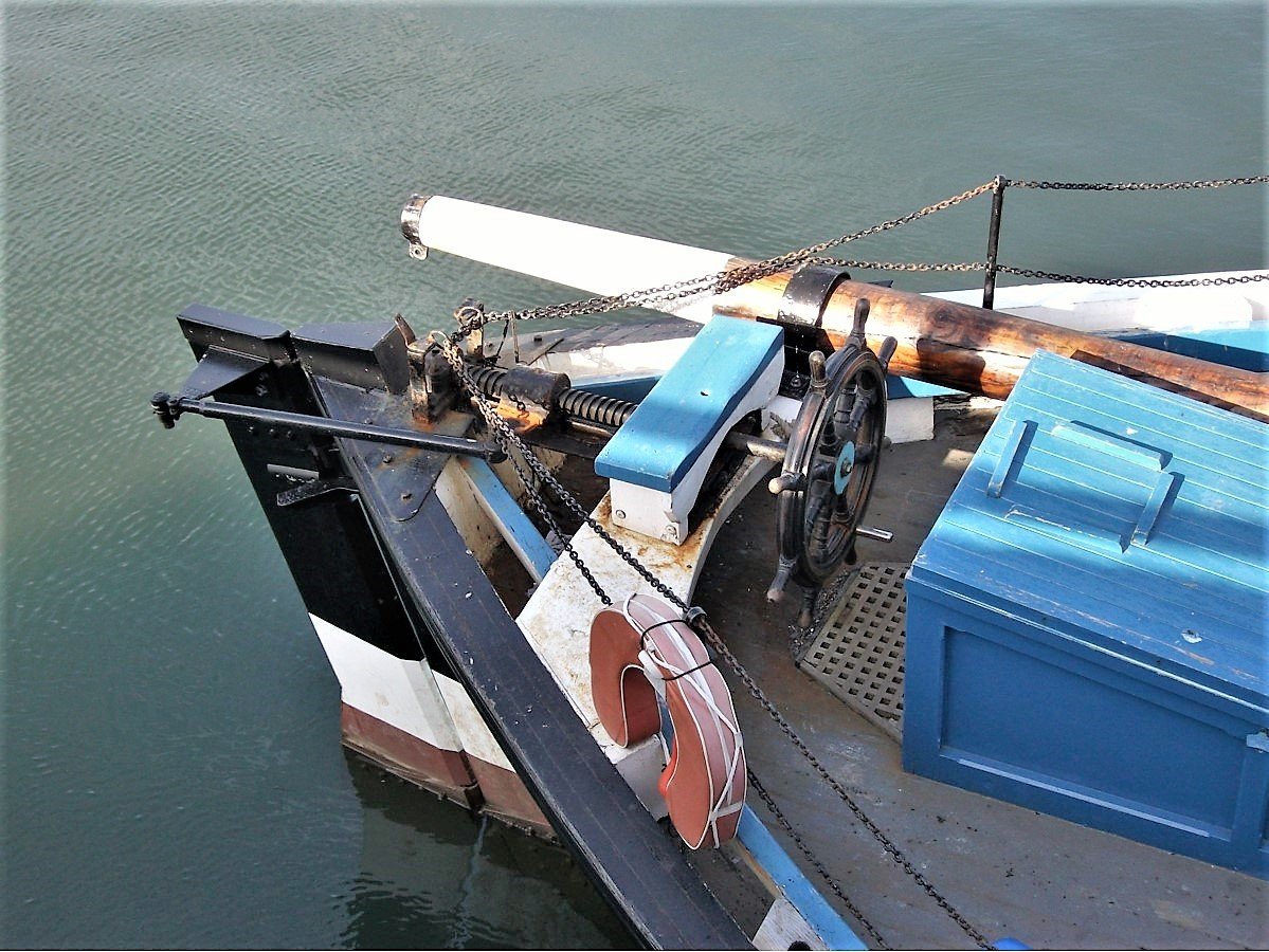
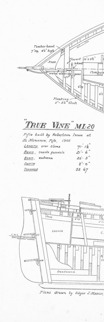
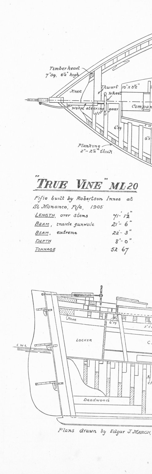
Thank you Rusty and Tim.👍 Post 20 Completing the tiller attachment. The final part is the attachment of tiller and worm drive. I have been hampered in my efforts by the lack of a detailed plan and I have had to rely on a visual interpretation from photo’s of the restored Fifie Reaper, and indistinct drawings and plan of the Fifie True Vine. Reaper What I am sure about is that these late 19th/early 20th century large Fifie’s did have the wheel close to the stern with some sort of mechanical attachment to work the rudder. It would be reasonable to run a shaft from the wheel to the stern post, covered by a narrow longitudinal box with a rod or stiff wire from the rudder, entering the box on the aft starboard side. True Vine Plan This is as much detail as provided on the True Vine plan. There is also a small drawing of a ‘boxed’ worm drive with dimensions in the book Sailing Drifters by Edgar J. March. 5798(2) The rod is 0.9mm ø micro brass tubing with a couple of etched brass eyebolts (PE2) from the kit inserted in the ends. 5800(2) The connecting ‘Bolts’ are formed from brass wire which hold the set up together. 5812(2) My interpretation is based on the Reaper set up. If further information comes to light I can make further modifications but for the present I am content to leave it at this point. B.E. 30/06/2020
.thumb.JPG.1c1b8945ec26e8b16d3dd1e3d83b8399.JPG)
.thumb.JPG.6533f9ad9d2c222022130dba224bf44d.JPG)


.thumb.JPG.b1b216aec3842225b738f824e826c83f.JPG)
- 195 replies
-
- 15
-
-
- lady eleanor
- vanguard models
- (and 1 more)
-
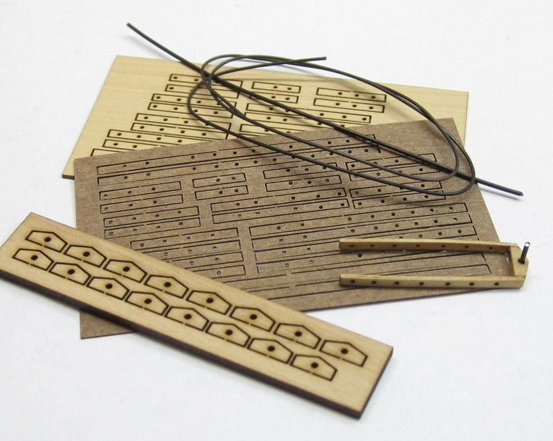
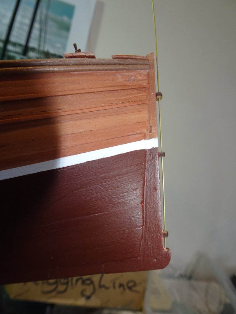
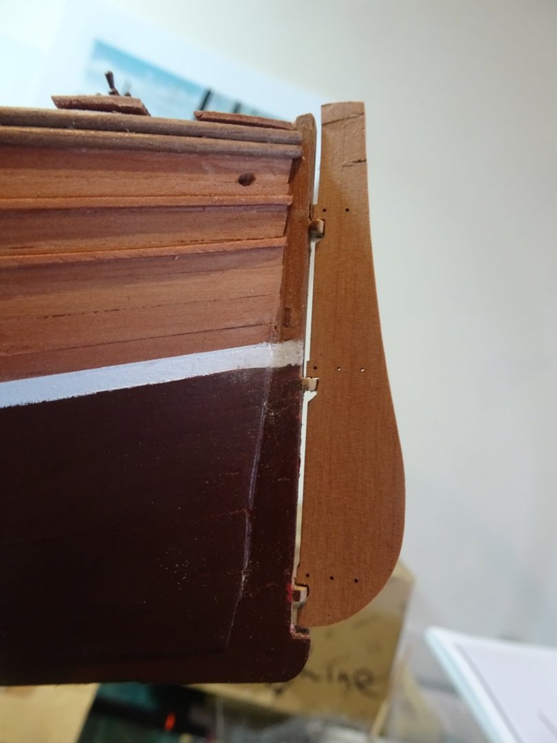
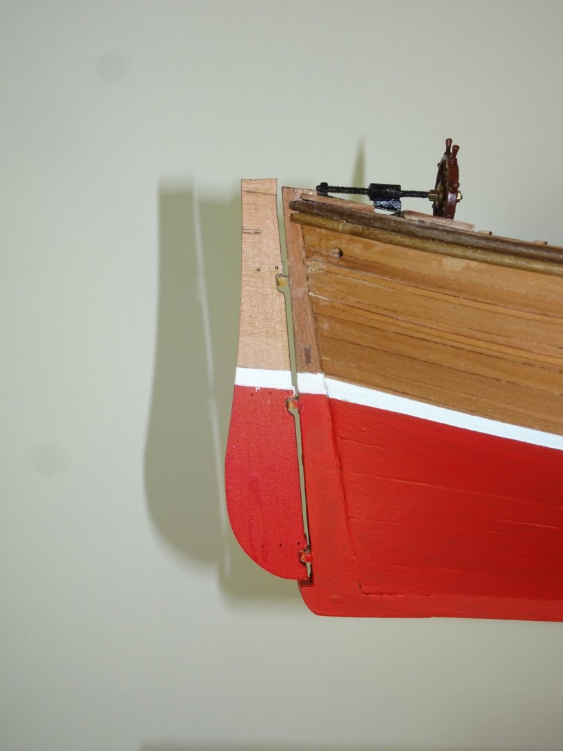
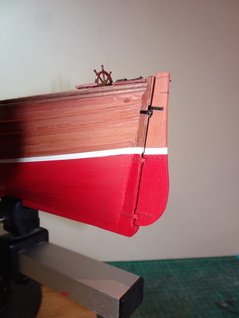
Post 19 The Rudder. Chris has created a simplified arrangement that takes out all the fiddliness usually associated with fitting a rudder. 5720 This has tenons on the rudder that slot into mortices on the stern post and hold the rudder in the correct position. Syren mini kit. I decided to fit a slightly more mobile set up using Chuck’s mini pintles and gudgeons kit. 5722 The gudgeons are shaped to suit and fitted to the stern post. I use a length of wire to align the holes for the pintles. 5725 First trial fit; pins have been inserted into the rudder to represent the pintles. With the rudder set I can now follow through with the paint lines. 5749 I decided to re-paint the lower hull Vallejo Matt Red, Mrs W said she preferred it, and that tipped the balance. On reflection I do think it suits the Pearwood contrast better. 5752 At this point I can trial fit the tiller iron on the rudder and the rod connection between rudder and worm drive. The finished version will hopefully be a little more detailed than a length of bent wire. 5783 One of the things I like about Chuck’s little rudder fittings kit are the boxwood and fibre straps. So much less fiddly than messing about with brass strip and looks good for scale. I represent the bolt heads with blobs of pva. 5791(2) The tiller arm now blackened is glued into place on the rudder. 5777(2) 5789(2) There is some remedial cosmetic stuff to do following my modifications, but I’m fairly satisfied with progress to date. B.E. 29/06/20

.thumb.JPG.bc2f7740391a0901865541b7f852f06a.JPG)
.thumb.JPG.29052d9c5fa63a93c2b2bfd0e3409d30.JPG)
.thumb.JPG.c4802721a9f369b4531530af7235c04c.JPG)
.thumb.JPG.b04b8d097d49f605fed62117a53b7b12.JPG)
- 195 replies
-
- 17
-
-
- lady eleanor
- vanguard models
- (and 1 more)
-
Great looking model Kevin, such realism, and I love the subtle weathering. ps every ship modeller should have a spaniel assistant.😉 Cheers, B.E.
- 337 replies
-
- 3
-
-
- finished
- mountfleet models
- (and 1 more)
-
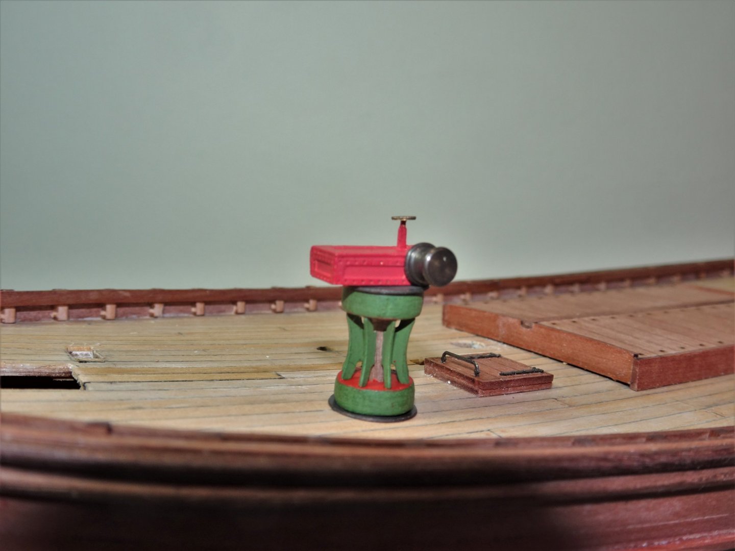
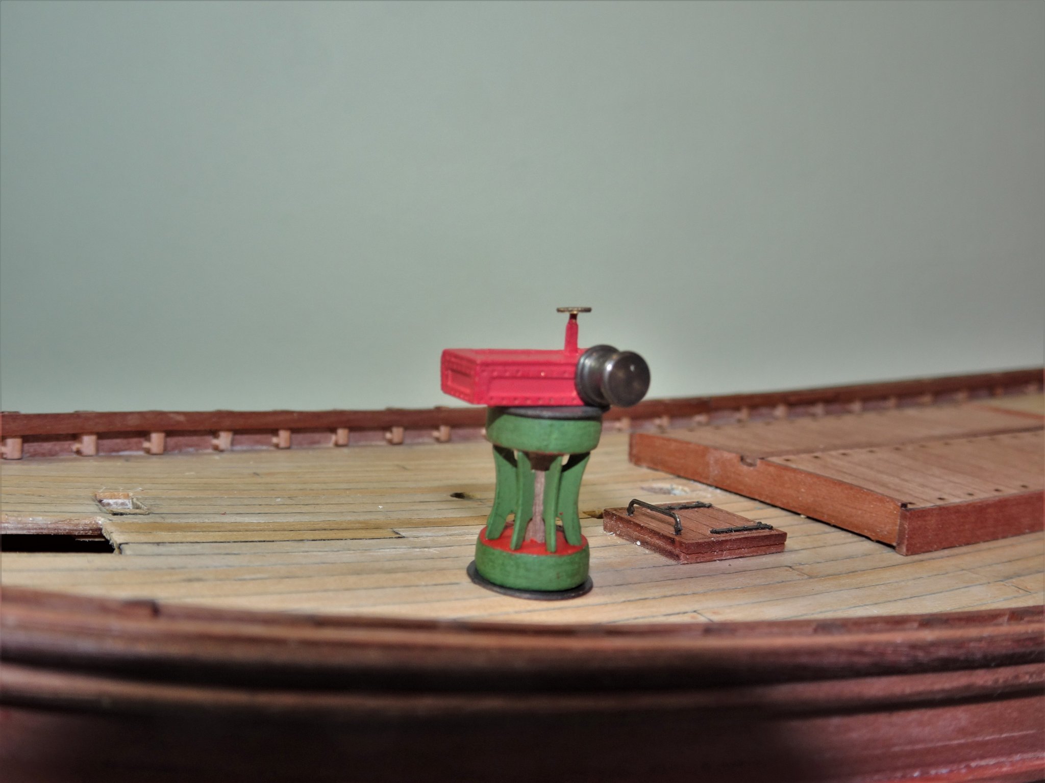
Post 18 The Capstan Elliott and Garrood steam capstans had been used on Fifie’s and similar since 1885, and one is provided in the kit. This is the most prominent and striking fitting on the deck, a real eye catcher, and beautifully presented by Chris. A combination of laser cut wooden parts and brass etch, which makes up into a fine little model. My most difficult decision; what colour scheme to use. 5730 The suggested scheme of red and green reminded me fondly of my old lawnmower resplendent with green casing and red cylinder blades, so I opted to go with that. I am using Humbrol enamel paint, Matt 80 (Green) and Vallejo Matt Red. Most time-consuming part is painting the whelps of the capstan. These eight fine etched parts required painting before assembly. The manual suggests that the drums be attached to the whelps without glue when assembling. I found that without glue the whelps had a tendency to fall out during the alignment so I resorted to a spot of ca to hold the whelps in one drum whilst I fiddled to align the other. The box atop the capstan fits over the end of the central spindle that runs thro’ the capstan body, (aka 3mm walnut dowel) 5729 A nicely turned brass warping drum is secured to the side of the box. I drilled mine to take a pin to secure it to the box and gave it a chemically blackened colour. 5732 Note:- there are two small holes in the side plates, I’m not sure what they are for, but they are not for securing the warp drum. 5731 The central spindle of the capstan is in reality a steam pipe. 5736 When fitting the small hand wheel atop the box I found it best to put a spot of ca on the connecting pipe and press it down on the wheel. B.E. 28/06/2020

- 195 replies
-
- 17
-
-
- lady eleanor
- vanguard models
- (and 1 more)
-
Before you glue everything down Tim, worth checking that the Bowsprit fits ok between the standards, and runs true thro' the securing ring. B.E.
- 436 replies
-
- 2
-
-
- vanguard models
- alert
- (and 1 more)
-
Fascinating subject, and a great job you're doing Keith. I love projects that require loads of additional research, frustrating at times, but adds to the build satisfaction no end. Regards, B.E.
-
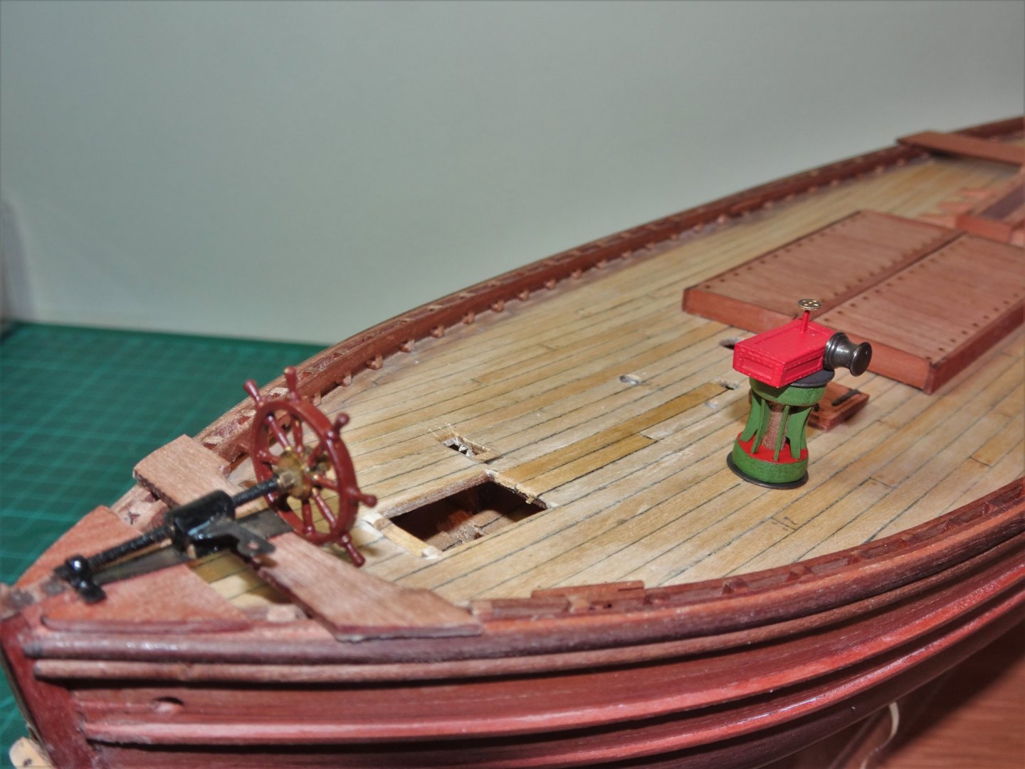
Thank you Grant, Jason, and Bob. @ Bob - The brass mechanism was chemically blackened, I always prefer to 'blacken' rather than paint metals, where possible. However, the wheel which is also brass I painted using Vallejo Hull Red, I didn't prime before painting. Regards, B.E.
- 195 replies
-
- 1
-
-
- lady eleanor
- vanguard models
- (and 1 more)
-
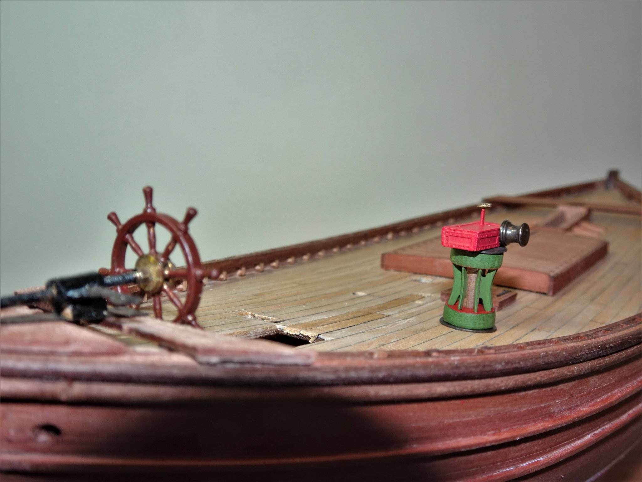
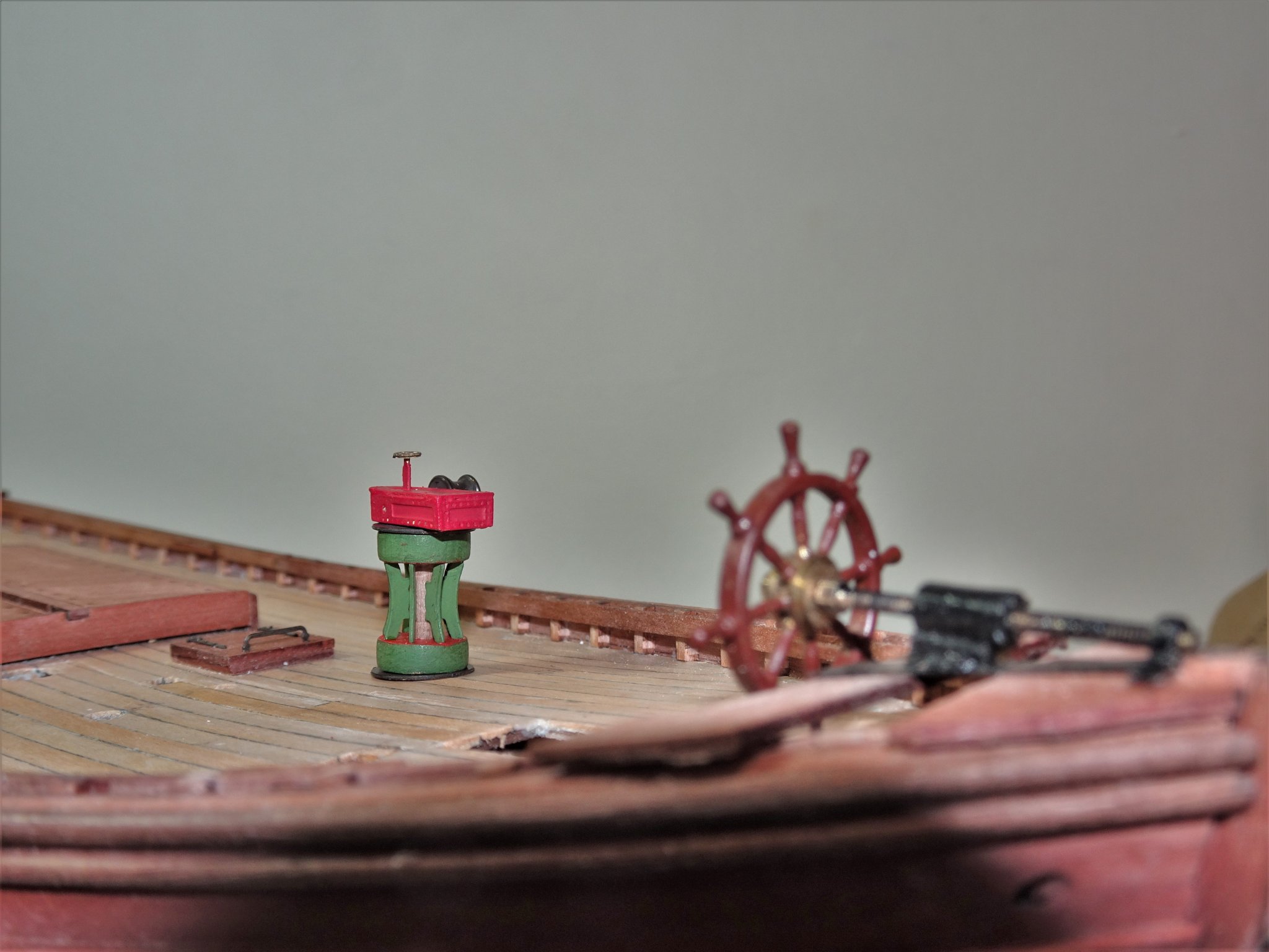
Post 17 Modifying the steering. The first thing to consider is the wheel and the worm drive. I’m not using the provided wheel but another of the same dimensions. For the worm drive and fittings, I obtained a length of M1.4mm threaded brass rod with associated nuts, Hex and open. 5641(2) I.4mm ø looks about right and importantly is a good fit for the centre of the wheel. The brass will be chemically blackened before fitting. Before I proceed too far a bit of de-construction is required. 5644 Replacing the deck planks where the holes for the wheel standards were cut. Not a great issue and quickly done. 5648 Once scraped they should blend in just fine. At this point I also put together the Companionway cover as this has a bearing for positioning the relocated wheel. I did make a minor modification to this altering the sliding canopy arrangement and using a proper ring bolt for the door handle. 5670(2) Next up I had to fabricate a thwart and a knee at the stern, both important for the addition of the steering gear to follow. An important item is the section along the worm to which the steering arm is attached. 5685(2) I made this from styrene tubing with nuts ca’d into each end thro which the worm will pass. One half of the provided tiller arm is slotted into this. 5680(2) At the aft end of the mechanism the worm screws into a supporting nut silver soldered to a plate. These are tiny and it took several goes to make the bond. 5689(3) One of the consequences of this modification is that the rudder needs to be tweaked to suit the revised steering mechanism. I added a small section to the top of the rudder and filled in the slot provided for the brass etched tiller arms. The mechanism is fitted into place after blackening and painting. Note one half of the etched tiller arms is used on the worm housing. 5711(2) The wheel is attached, and the rod trimmed to length. 5710(2) 5707(2) This is as far as I can take it at present, I need to complete the rudder before the connection can be made. B.E. 25/06/20
.thumb.JPG.7f0a07f9ce6fb2dd43d0888af94224cd.JPG)

.thumb.JPG.2bb2cc6ebe37eb5fe2114f5392387fba.JPG)
.thumb.JPG.2f4f66fa6e3c327056b1223bc21181fc.JPG)
.thumb.JPG.7bb94008134803f69ff24e7812c807ba.JPG)
.thumb.JPG.94133a4644f6ff328c969f376fdcfe35.JPG)
.thumb.JPG.88084f4f0dc4b0f37a7acbe653ec372a.JPG)
.thumb.JPG.d089b8d5aa8b5c981685c6565a02deda.JPG)
.thumb.JPG.550963d839951cb45b7e625d4b0923af.JPG)
- 195 replies
-
- 19
-
-
- lady eleanor
- vanguard models
- (and 1 more)
-
Cheers Dirk, I'll have a look 👍 Thanks for the reference Alan, I'll look it up. I had clocked the validity of the horizontal wheel on the Zulu's, and looks just right on the Zulu model as depicted. The Fifie is a different matter, but at least we have photo's of a more credible arrangement. B.E.
- 195 replies
-
- 3
-
-
- lady eleanor
- vanguard models
- (and 1 more)
-
It would be great if I could make it that way Yves, but don't hold your breath.😃 The engineering parts to effect a working rudder would be very small indeed, tough enough with a static rudder. B.E.
- 195 replies
-
- 4
-
-
- lady eleanor
- vanguard models
- (and 1 more)
-
That's a shame Jamie, but I've found there is not much you can't deconstruct on a wooden boat if you have the will. Metal parts stuck with ca can be removed using Acetone, and pva glue by water and isopropanol. I can understand your reluctance to perhaps get into something you're not comfortable with, so maybe it's a case of putting it down to experience and resolve to do better next time. Regards, B.E.
-
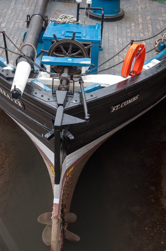
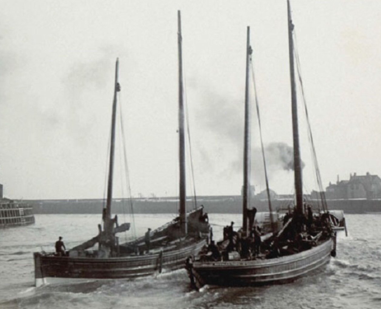
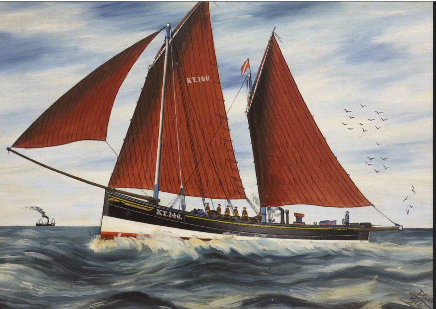
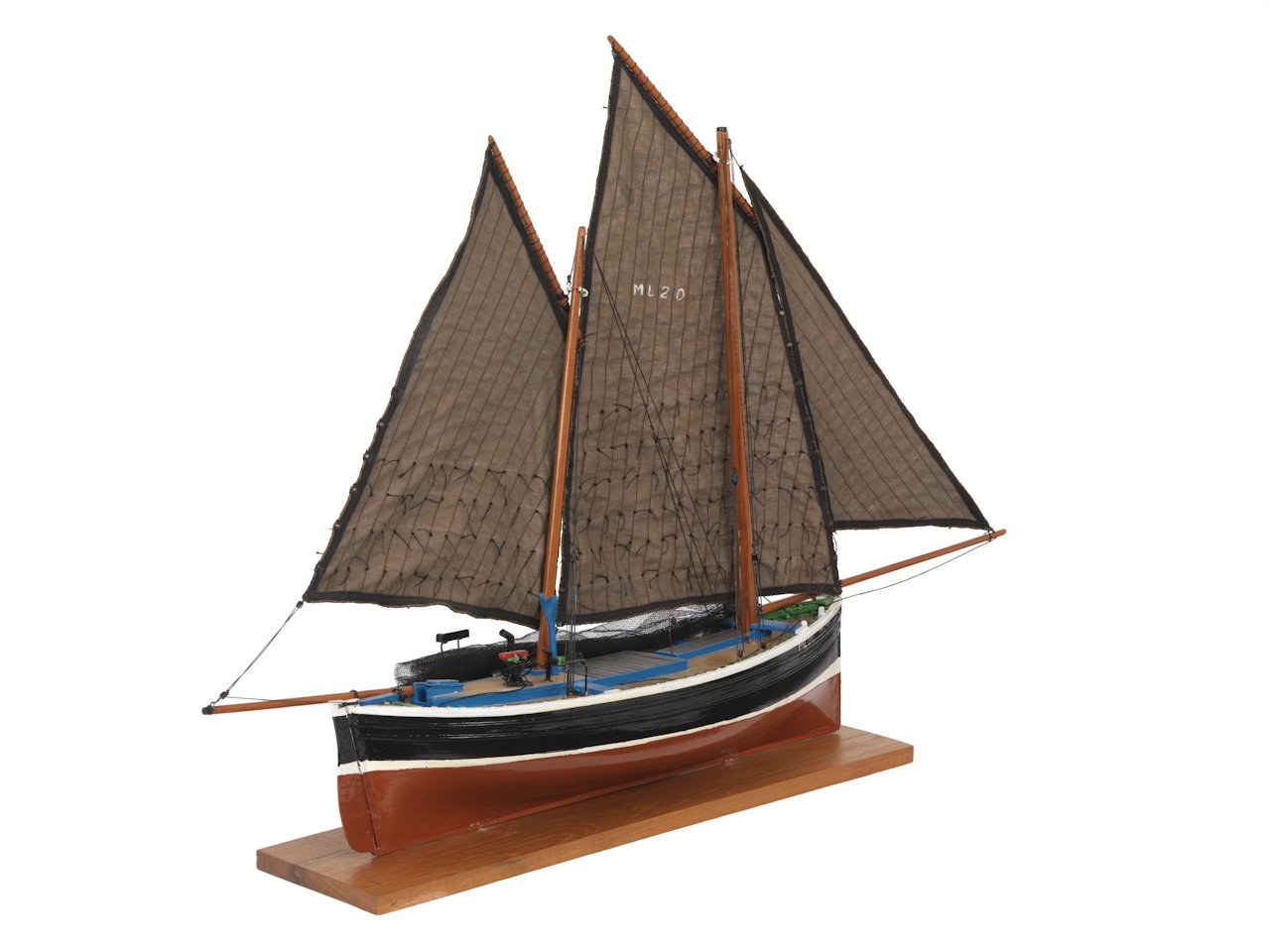
Thank you, James, Derek, and Ernie, looks like Hull Red it is. 🙂 and Derek and Ernie, - I don't think you will be disappointed with this sweet little project, nice lines, beautifully made sails, and a model that can sit on a mantle shelf with ease, casing not necessary. Post 16 What to do about steering? I have struggled to accept the steering arrangement as presented in the kit, which may be a simplification as Chris notes in the manual that the kit has been developed with the beginner in mind, and some aspects have been simplified. To my jaundiced old eyes the whole set-up looks more 18th century than the dawn of the 20th century, and distance from the stern to the wheel is also quite puzzling requiring whatever control cables there were to run through the cabin to reach the wheel. My best guess is that it would represent some sort of drum drive system worked off cables, but the wheel seems a long way from the stern. None of the many photo’s and plans I have scoured on vessels of this type have the wheel arrangement as seen on the kit version. What is indicated is a worm screw system used on these large later period Fifie’s and Zulu’s, probably from the last years of the 19th century, and certainly from the early years of the 20th century. The kit deck layout generally seems to have been taken from the still existing and restored Reaper 1902 and I have decided to modify my version of the kit to better reflect a large early 20th century Fifie. The arrangement from the plans of the True Vine 1905 drawn by Edgar March show the wheel set just inboard of the stern set in a housing with a worm employed to operate the steering. True Vine Here’s a model of the ‘True Vine’ held in the NMM. A worm screw drive is in place. I have to thank Lane Duncan, secretary of the Scottish Fishing Museum model boat club for these clear photo’s of the steering set up on Reaper. It is from these photo’s that I hope to make the modifications to the kit. The wheel position is clearly evident from the Fifie on the left of this photo dated 1904. It looks to me like they are being towed out of harbour by a steam paddle tug. This painting also shows the arrangement with a worm screw. The tricky part now is how to represent what the photo’s show. B.E 23/06/20
- 195 replies
-
- 15
-
-
- lady eleanor
- vanguard models
- (and 1 more)
-
She's looking impressive Jamie, not an easy model for a first build. I don't know if you can backtrack at this stage but there is a significant error with the lower shrouds. They should pass down through the lower tops not over the outside edge, If you can modify this I would. The upper shrouds look correctly positioned. B.E.
-
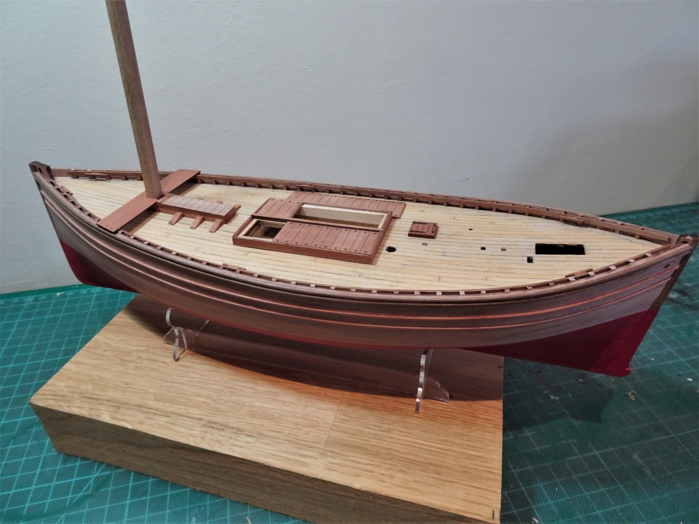
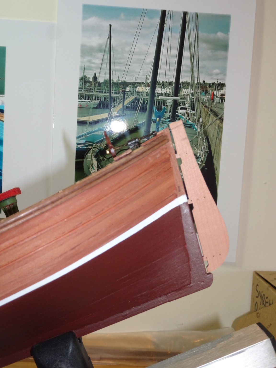
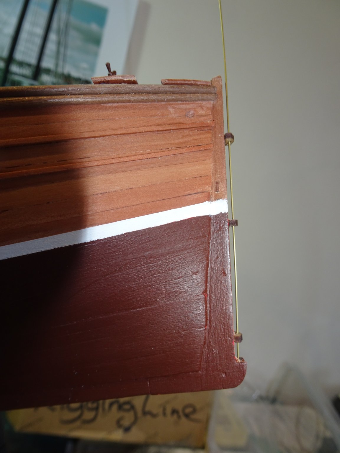
Post 15 Back to Hull painting The lower hull has been repainted using Vallejo Hull Red a much darker almost chocolate shade. 5622(2) The hull is masked off to do the White Boot topping. 5615(2) Needed a bit of fiddling to get the lines matching and looking good to my eye whilst fervently hoping there would be no bleed. 5624(2) I am using Vallejo White for the topping. I applied several coats before removing the tape. 5628(2) Micro bits of bleed can be cleaned up without the need to re-do the whole. 5640(2) With the Topping completed I can now apply wipe-on-poly to the natural Pearwood. 5639(2) It brings out the natural beauty of the Pearwood. 5636(2) Got a slight niggle in my mind whether I like the Hull Red finish as much as the Flat red previously used, but I’ll let that percolate for a while. I now need to get back the subject of the steering layout before I can progress further. B.E. 22/06/20
.thumb.JPG.3424ee1a274bd452374b5fc86c97e448.JPG)
.thumb.JPG.0a4ab292c3b80b2ed150dec3c0d0042b.JPG)
.thumb.JPG.2df494e253de3bcf08125f36aac465b3.JPG)
.thumb.JPG.3b9b51cdba0068835cdbf5a6c732e6d8.JPG)
.thumb.JPG.569d1a82dd540f023a1ad0f3cc1c74ad.JPG)
.thumb.JPG.ad7d5e09a5c3172f16b443dcd3f30a63.JPG)
.thumb.JPG.3ffaba8d901e80c048d69dba1ee3fa8b.JPG)
- 195 replies
-
- 17
-
-
- lady eleanor
- vanguard models
- (and 1 more)
-
Looks good to my eye Glenn, Cheerful looks so impressive with those nice woods. I certainly wouldn't use sanding sealer on quality woods like Box and similar. B.E.
- 778 replies
-
- 3
-
-
- cheerful
- Syren Ship Model Company
- (and 1 more)
-
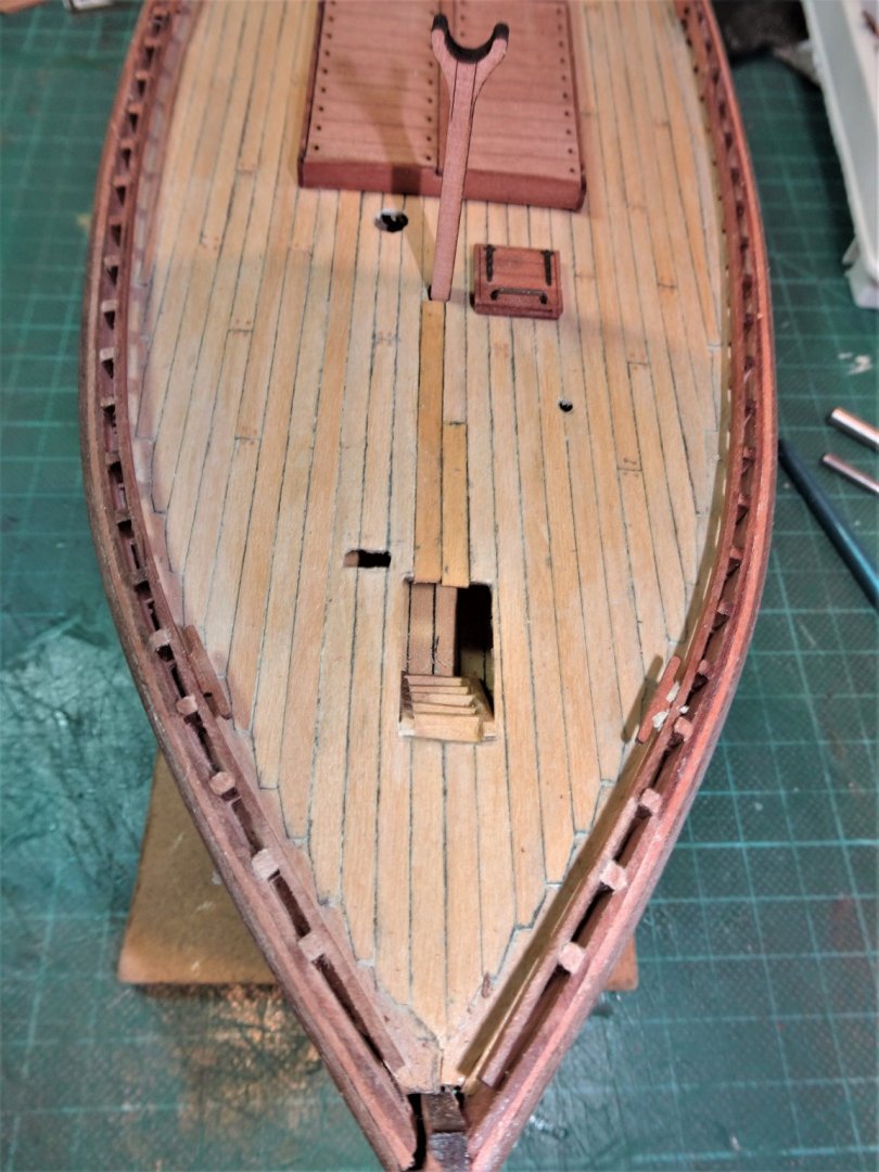
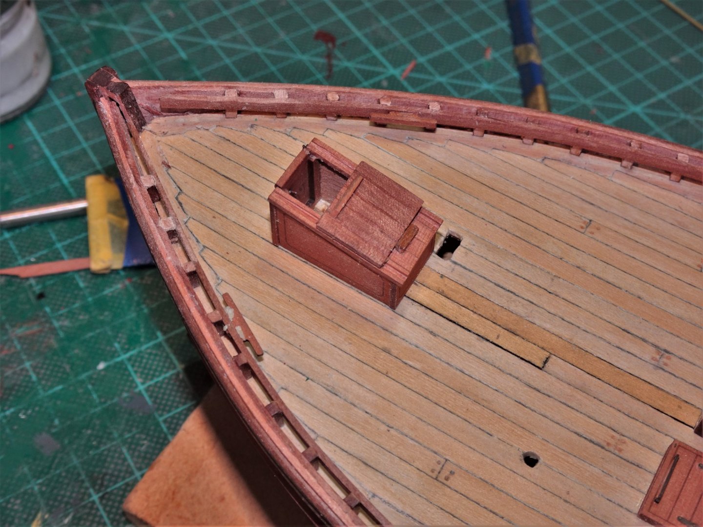
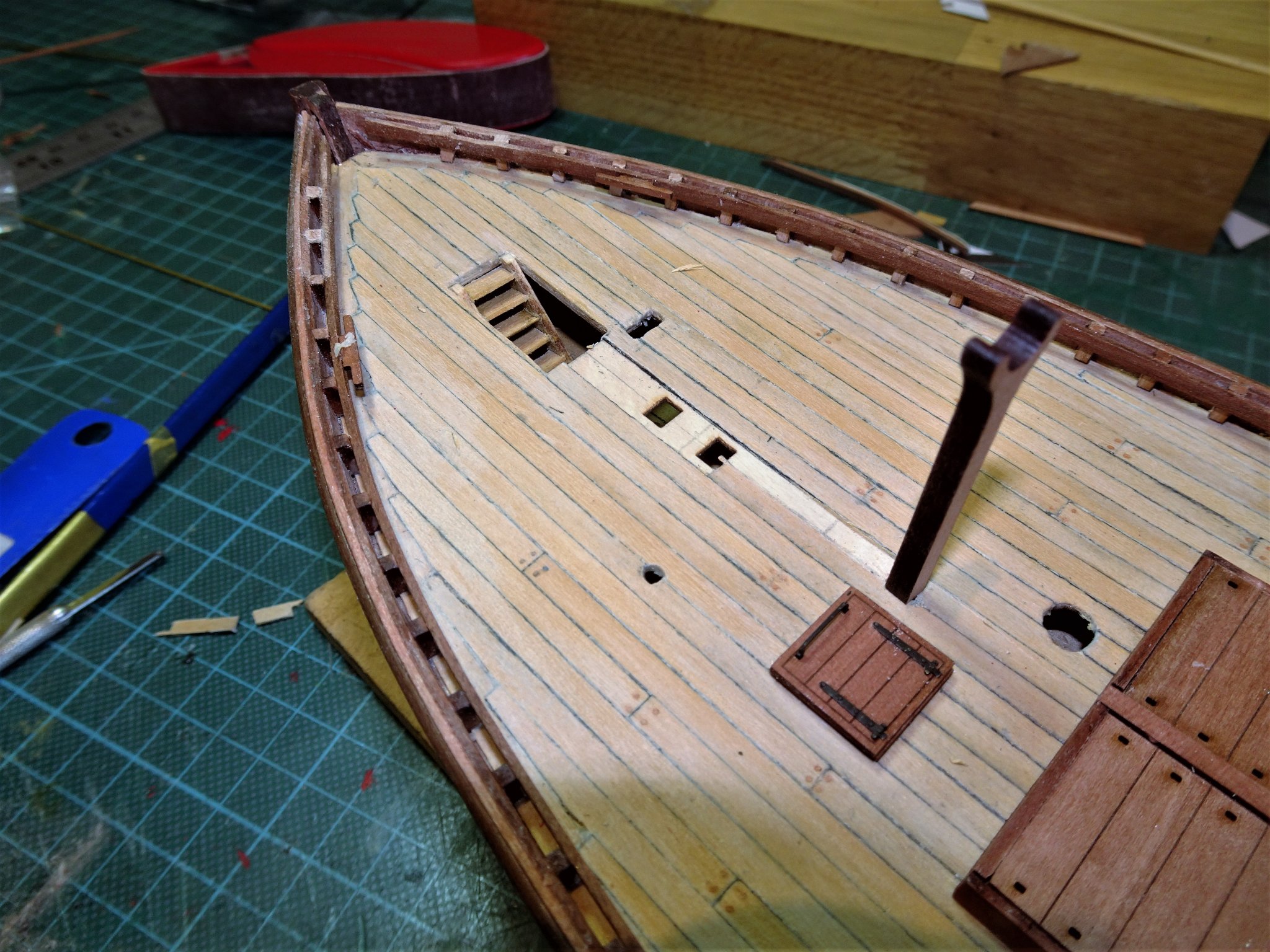
Post 14 Back on the deck As I have completed the deck it seems appropriate to fit the timberheads at this time. It is a tedious job fitting all these position specific tiny sections along the bulwark but Chris has done an excellent job with the etched pearwood, which saves a lot of extra fiddling which would otherwise be the case. 5601(2) Care must be taken when handling these pieces, they have an inbuilt drive to ping off into the ether never to be seen again. 5608 I am now into that part of a build I like best, fiddling with the fittings. The fish hatch is the largest fitting on the deck and one that is easy to modify slightly to provide more interest. The kit provides an all-in-one representation of the boards that form the cover. 5602(2) I prefer to have sections open to view, with a glimpse of the nets, (detail to follow) in the fish hold. The boards were modified to allow this. The board lifting rings are represented in the kit by less than convincing eyebolts. I will replace these with ring bolts, tedious as it is. The Fore Mast Housing This fitting allows the Foremast to be lowered by means of a Tabernacle. This is hidden below decks so it’s not something I need to be concerned about representing, but the model can still be displayed with the mast in the lowered position if desired. 5607(2) The make- up of this part is a firm fit and I didn’t need to glue the side pieces in place. The broad thwart is also glued into place. 5598(2) I did test fit the Fore mast timber (6mm) walnut square stuff which was a tad oversize for the space, but rather than trim the mast I sanded the inside the side pieces to get a snug fit. 5600(2) 5605(2) This is about as far as I can go with the deck fittings at present. I have some concerns about the steering arrangements and representation and position of the wheel on this sail only vessel. There may have to be some deconstruction/ modification in this area. I have to say I am thoroughly enjoying this build, a departure from my usual 18th century naval subjects. Researching this vessel type is a new interest and I have been in touch with the Curator of the Scottish Fisheries Museum who has provided very useful additional information. Cheers, B.E. 20/06/20
.thumb.JPG.b1f2a8d1a5180c76f98d4cd3e2d0401c.JPG)
.thumb.JPG.ee5b4ddaee79e6d4d3115fc20e617630.JPG)
.thumb.JPG.8f080e62c37a6e3628891d3cc3daafcc.JPG)
.thumb.JPG.6c15f5b84600df864971f94991dae643.JPG)
.thumb.JPG.3b34ad8184977141574eb5fbc32fd040.JPG)
.thumb.JPG.28cc8a1d5e45da97fda29b529d958c60.JPG)
- 195 replies
-
- 15
-
-
- lady eleanor
- vanguard models
- (and 1 more)
-
Removing a link
Blue Ensign replied to Blue Ensign's topic in Using the MSW forum - **NO MODELING CONTENT IN THIS SUB-FORUM**
Thank you James, it's damned embarrassing when you forget how to do things🙄 and thanks Steven and Tim for your advice. B.E. -
I've done something weird whilst trying to update my signature and add a link to my Alert build. I've ended up with a large photo, which I don't know how to get rid off. There doesn't seem to be a delete button. Advice please B.E.
-
Hi Bob, Becc are a manufacturer in the UK of model accessories, notably flags. Their products can be found in many online ship modelling supply sites. B.E.
- 195 replies
-
- 1
-
-
- lady eleanor
- vanguard models
- (and 1 more)
-
Coming along very nicely Tim, pretty little thing isn't she. 🙂 B.E.
- 436 replies
-
- 3
-
-
- vanguard models
- alert
- (and 1 more)
-
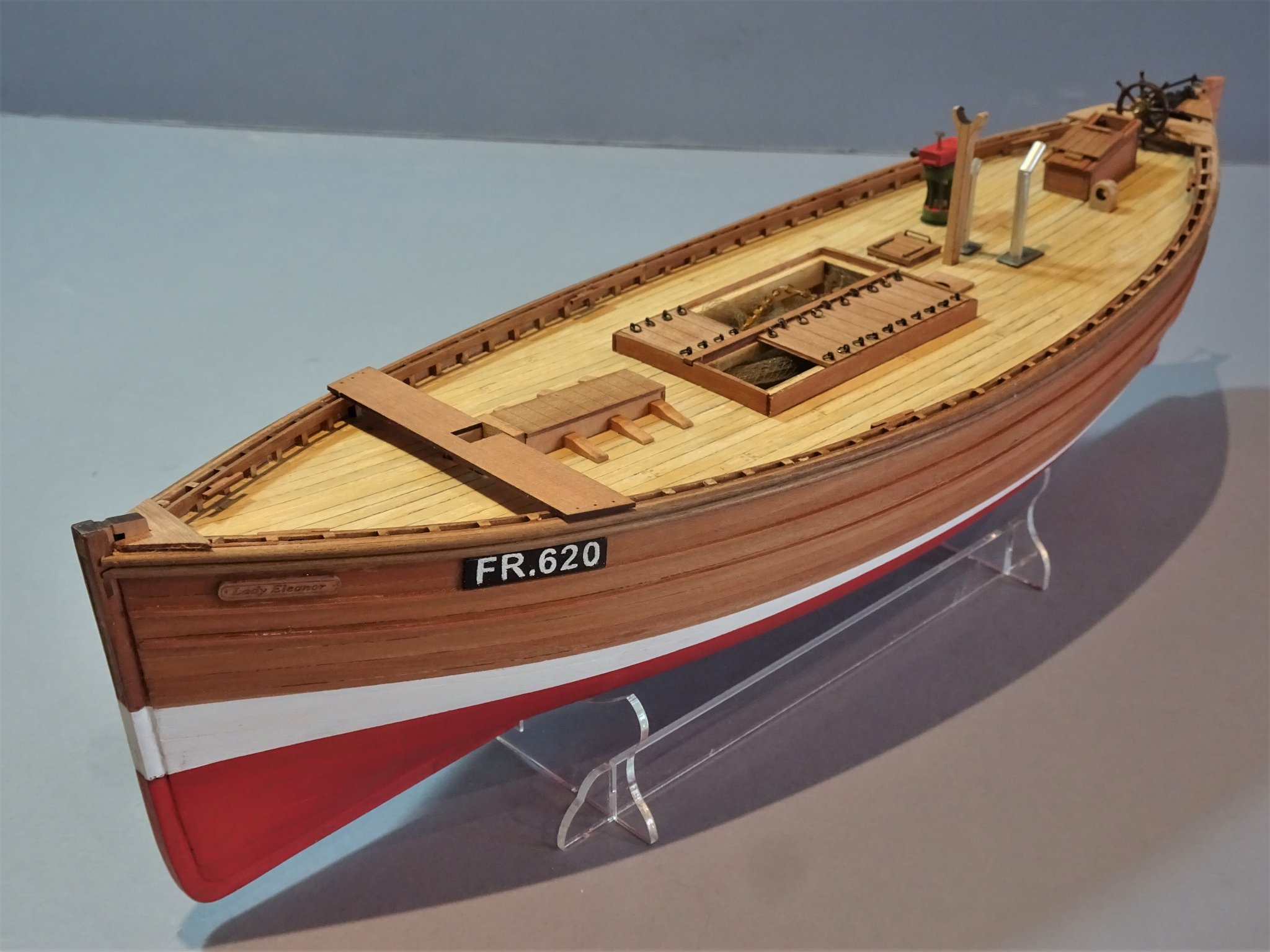
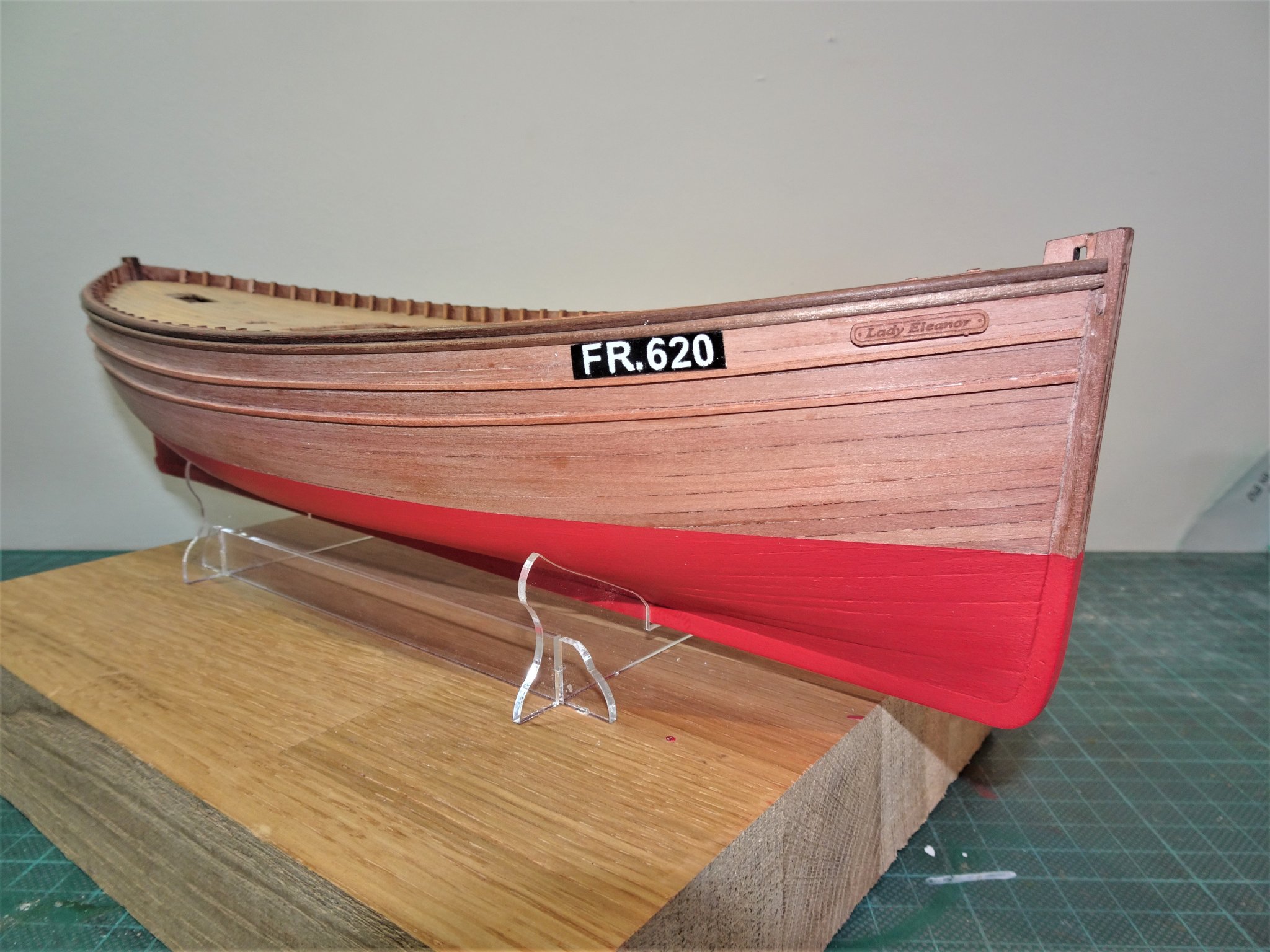
Post 13 A Brief diversion from the main event. Included in the kit is a beautifully etched name plate for the Lady Eleanor. What isn’t included in the kit is the Registration Number, something every fishing vessel would have. So, I decided Lady Eleanor should have one too. As Fraserburgh was a centre of the North East herring fishing trade I used the letter code FR. For the number I decided on 620 being the month and year of the model build. It wasn’t by accident that I decided on fitting the first rubbing strake 6mm below the top strakes. This is the space required for the Registration plate. To make the plate I used a 6mm wide Boxwood strip, and for the characters BECC 5mm vinyl. 5563(2) The lettering is gold which I don’t want, these registration plates seemed to have white lettering on a black board. The answer is to paint the board white, apply the letters, paint over with a waterproof black marker, and hope the result is as desired once the letters are peeled off. 5568(2) Well not quite, there was a little bleed beneath the vinyl which required touching in, but I quite like the result. 5576(2) 5578(2) For a simpler approach Becc do supply 5mm white letter/number sets which could simply be fitted on a black board. Just a small enhancement but now back to the build. B.E. 17/06/20
.thumb.JPG.c97bc4f0fae7d7cd7aa495da980d140a.JPG)
.thumb.JPG.4052c4b590a76d7e813160ceeeedf374.JPG)

.thumb.JPG.ef527dd8eabb4f30f6b4a79fe61bbefb.JPG)
- 195 replies
-
- 17
-
-
- lady eleanor
- vanguard models
- (and 1 more)
.JPG.5d4e2cb5df74dce65f3317a905556909.JPG)


.JPG.349245622ed45fc795649423a6b26b93.JPG)


.JPG.6b8f7b964d96257b2751aa162ccfbade.JPG)
.JPG.c2377a2e102dc9560f0e01e023023e01.JPG)

.JPG.85ad22138609a9c8060d34a76e731e05.JPG)


.JPG.2db9156b7eea61af27f45da26ed52c23.JPG)
.JPG.e9e61eb03b1b212a91a306408fb3eae6.JPG)

.JPG.56ee80a78de28a0db481a4a4f81dee53.JPG)
.JPG.1ca246a1c7a0b36a264fef8958d8eedf.JPG)


.JPG.20c348030bba25c804d4714bbb602a04.JPG)


.JPG.aabc29403afd0b134b778318e3f6b330.JPG)
.JPG.4385efca774b2dd1497211614fef089e.JPG)
.JPG.954064a37cbf03f7022975bf21fea6e6.JPG)
.JPG.d2480e8b770513de726671fd91bb9a64.JPG)
.JPG.d1deab69fad8362242bfc7f2fff469f5.JPG)
.JPG.fd3b2ee481dbd0995e7026ffd9161c3e.JPG)
.JPG.bdf90a8d4b0544efad1e917d718a021e.JPG)

.JPG.afb8a66ae823d1b6a3607b071ae0d799.JPG)
.JPG.e21ad329a5503eb8ea0bc1e1492005e2.JPG)
.JPG.8757ae7a2c0630dc8df4ac9e291caada.JPG)
.JPG.943f9e00168742b2312f21a2bd7d1f60.JPG)
.JPG.ec9753143075fe134b1854f4f81c6315.JPG)
.JPG.ef46c3fe5ee6e7646871ab550895ae60.JPG)
.JPG.aba886adf64ba0a43b460e114d7b510f.JPG)
.JPG.105ccc04e78c301986a47496c6b6abf5.JPG)
.JPG.26dbcbdc777931760374c81bc0741288.JPG)
.JPG.42f85161c8d0f45c48ee9c99a71f0a19.JPG)
.JPG.da430f729b7211a68201a15991f59e01.JPG)
.JPG.9b9a1fde97d77ce1defde5708d230911.JPG)
.JPG.8ba9ff252491eca55d488a7fe528a25b.JPG)

.JPG.6facbae16d8c9d117658f787c5305dfc.JPG)
.JPG.8c6ab5021c5df6110ebcd43c22962843.JPG)
.JPG.d26eff90e11309fa74385b28faa47fcb.JPG)