.JPG.ca33079f5815b861e67b9c2cccd37982.JPG)

Blue Ensign
-
Posts
4,564 -
Joined
-
Last visited
Content Type
Profiles
Forums
Gallery
Events
Everything posted by Blue Ensign
-
 Cheers Dirk, In that case I will use the 0.7mm thick stuff, it is very pliable and has an adequate range of widths, I did use it for the exterior planking and deck planking on my Pegasus build. Regards, B.E.
- 335 replies
-
- 1
-

-
- alert
- vanguard models
- (and 1 more)
-
Thanks Dirk, I do have a supply of Boxwood strip of a nominal 0.7mm in varying widths which I was thinking of using. I thought with such a thin strip I wouldn't have to attempt rebating the upper edges of the strakes, the downside of course is that there is little room for sanding out mistakes. When you did your clinker planking did you find that differing strip widths were needed? Regards, B.E.
-
So am I Kurt,😃 I haven't yet formulated my approach to the clinker planking , I will give my full attention to that once I have completed the topside planking down to the Wale. Goodwin gives the size of the planking as approx 12" broad amidships and 2½" thick (4.76mm x1mm ) at scale. Looking at the book drawings they seem to equate to 6mm x1mm boards with a rabbet of 1.5mm to a depth of 0.25mm. The Garboard plank looks to be 9mm wide at mid point. I do have a fair range of timbers of varying widths and thicknesses. Cheers, B.E.
-
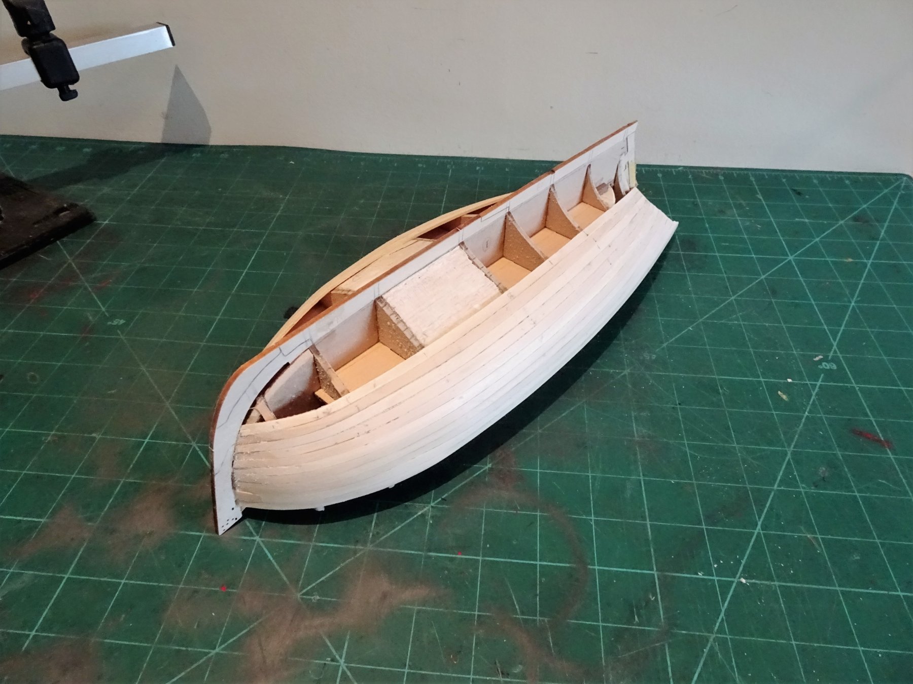
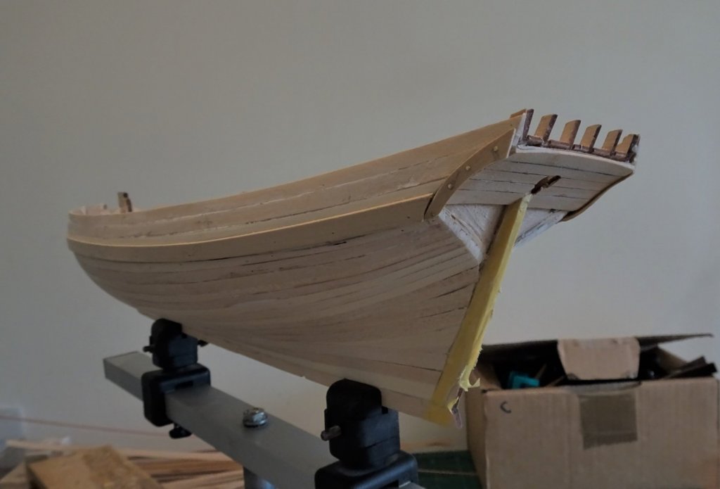
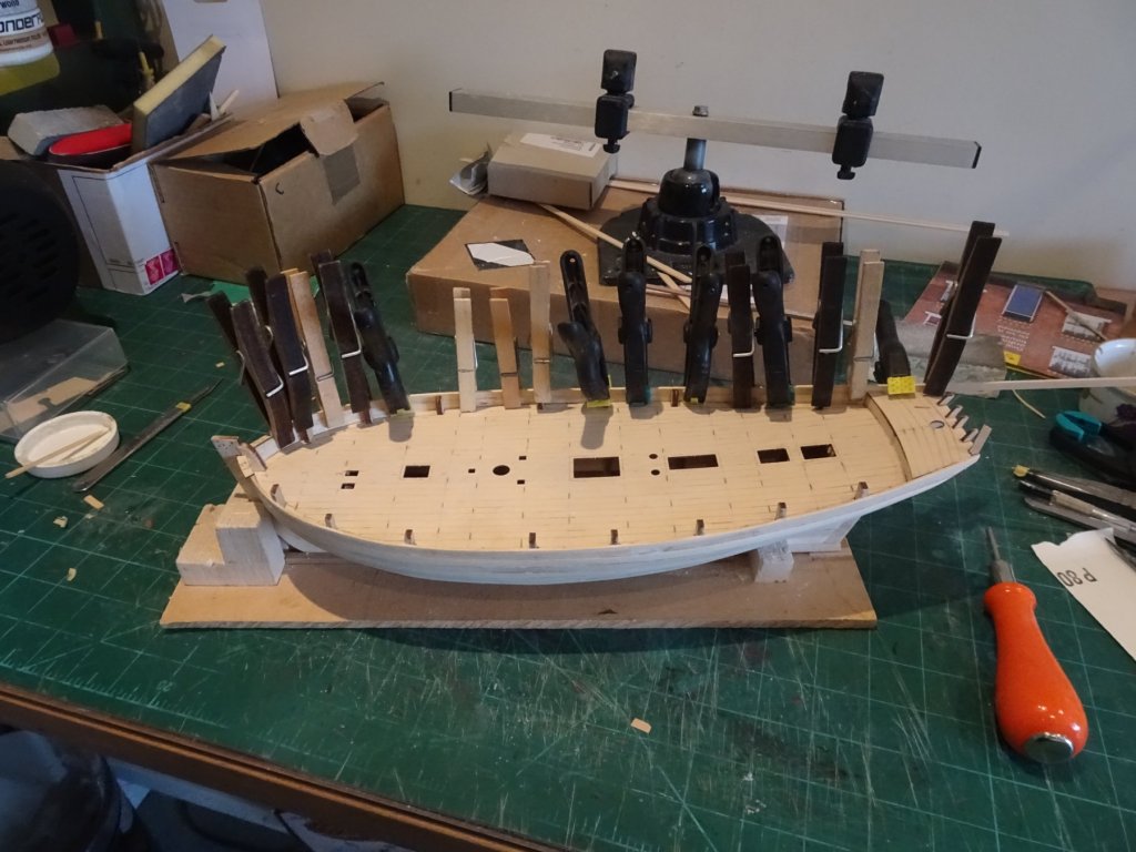
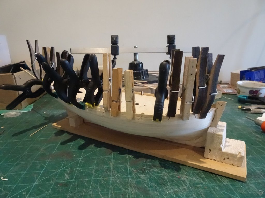
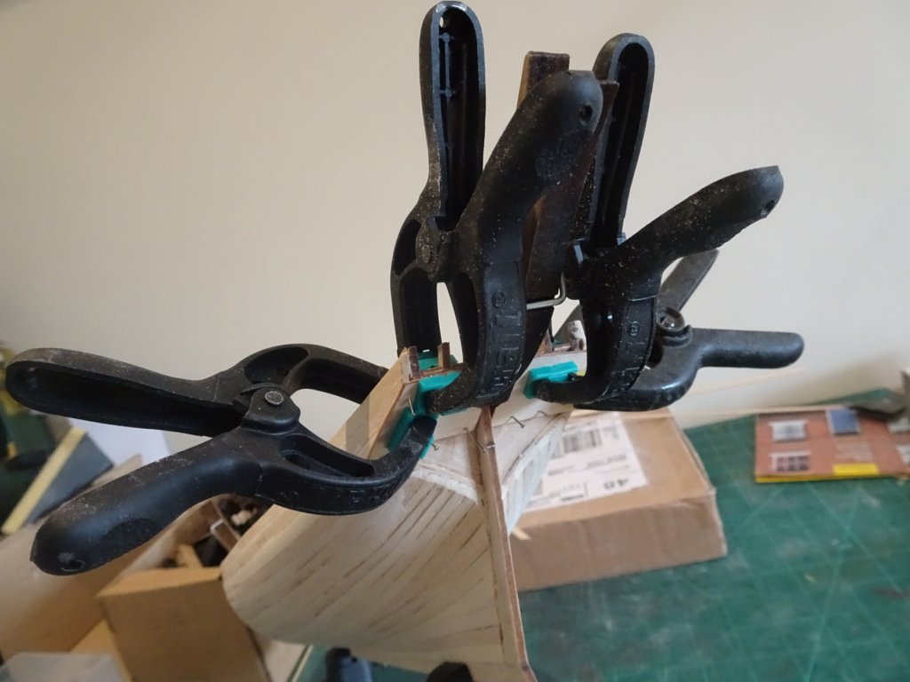
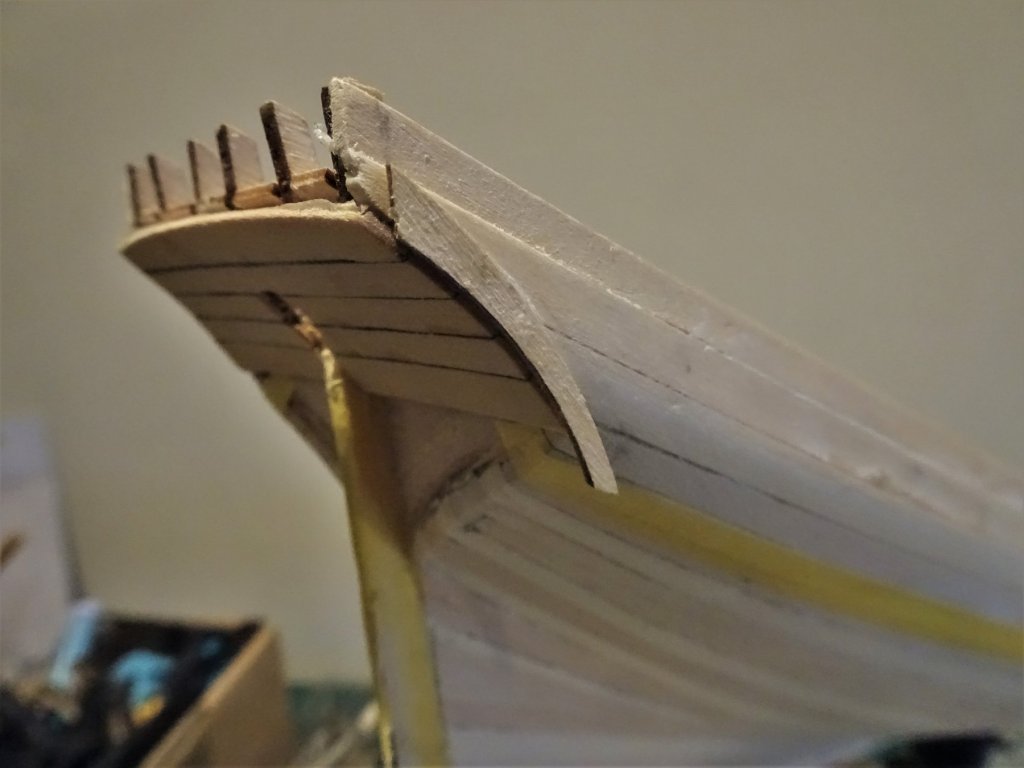
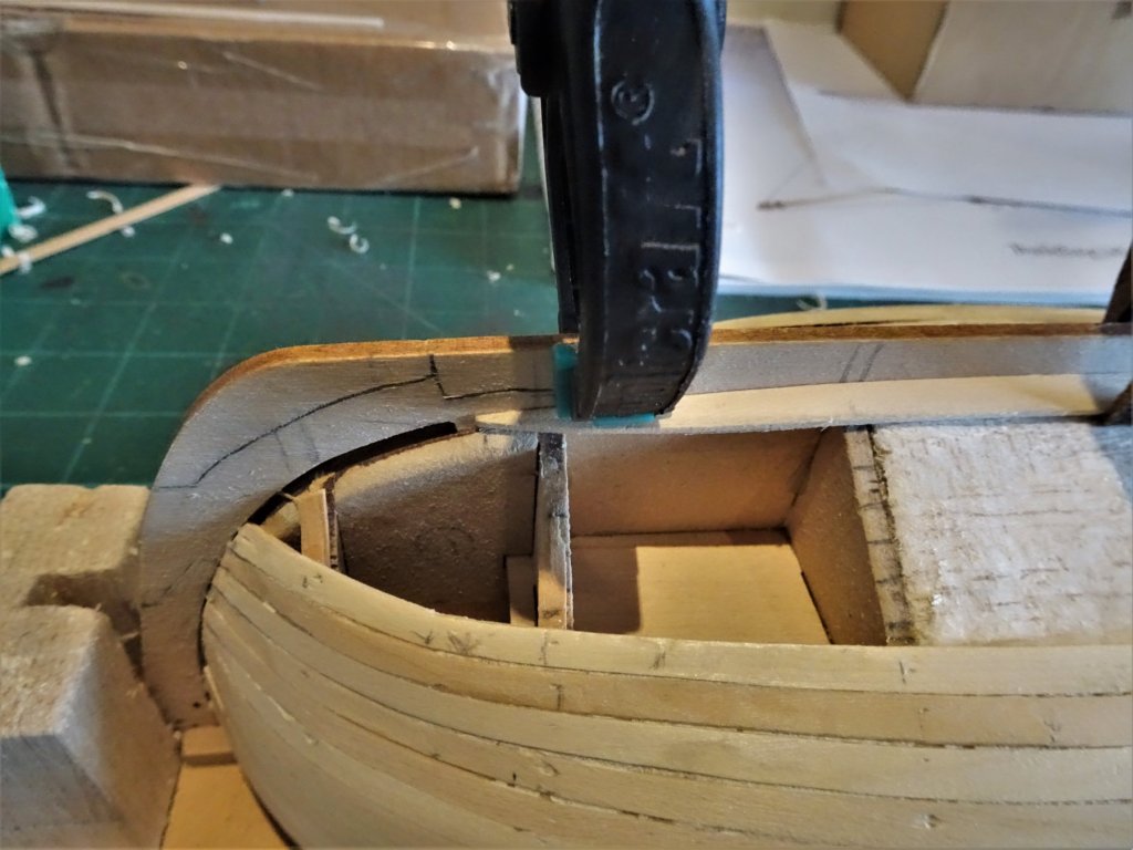
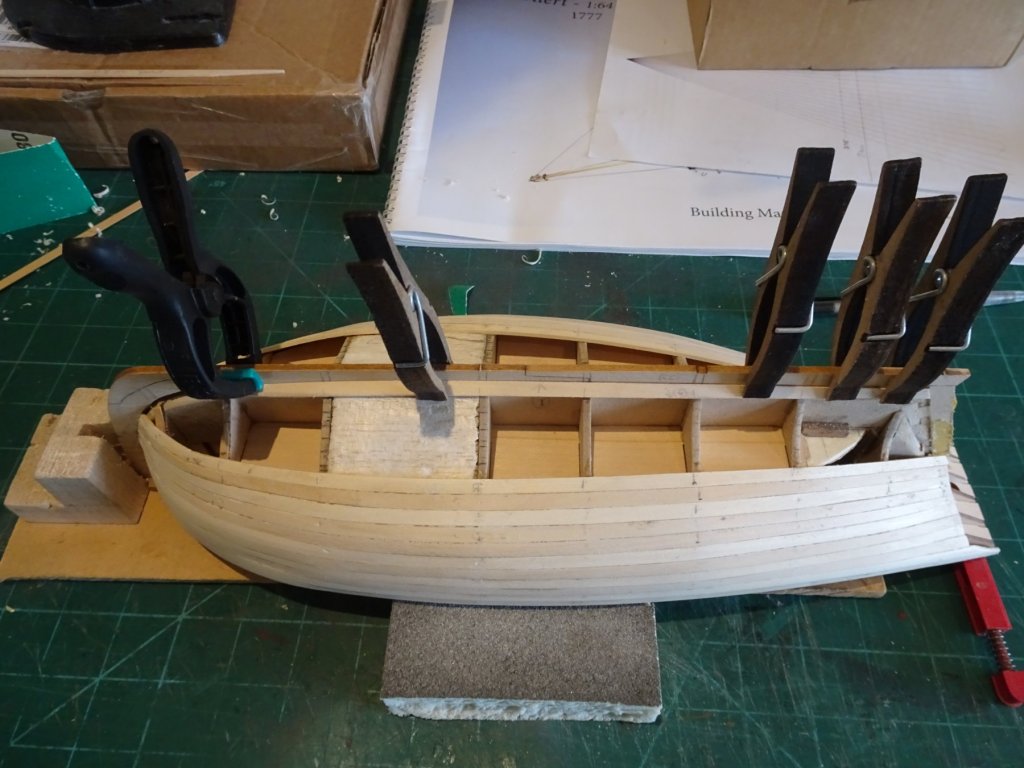
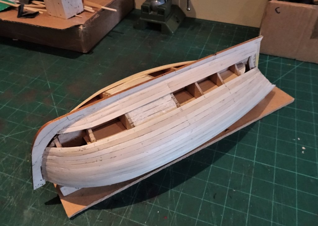
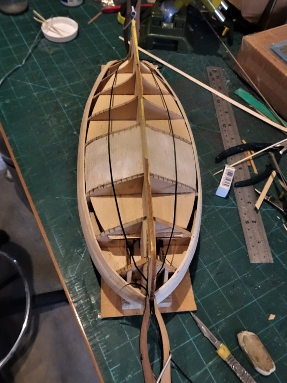
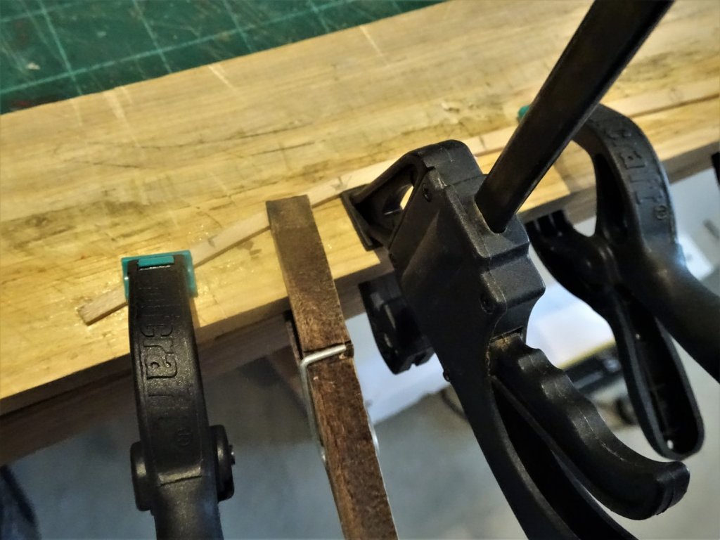
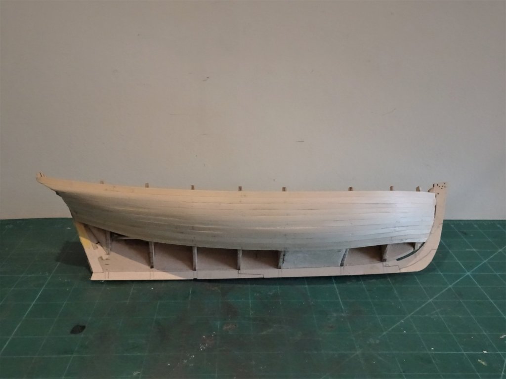
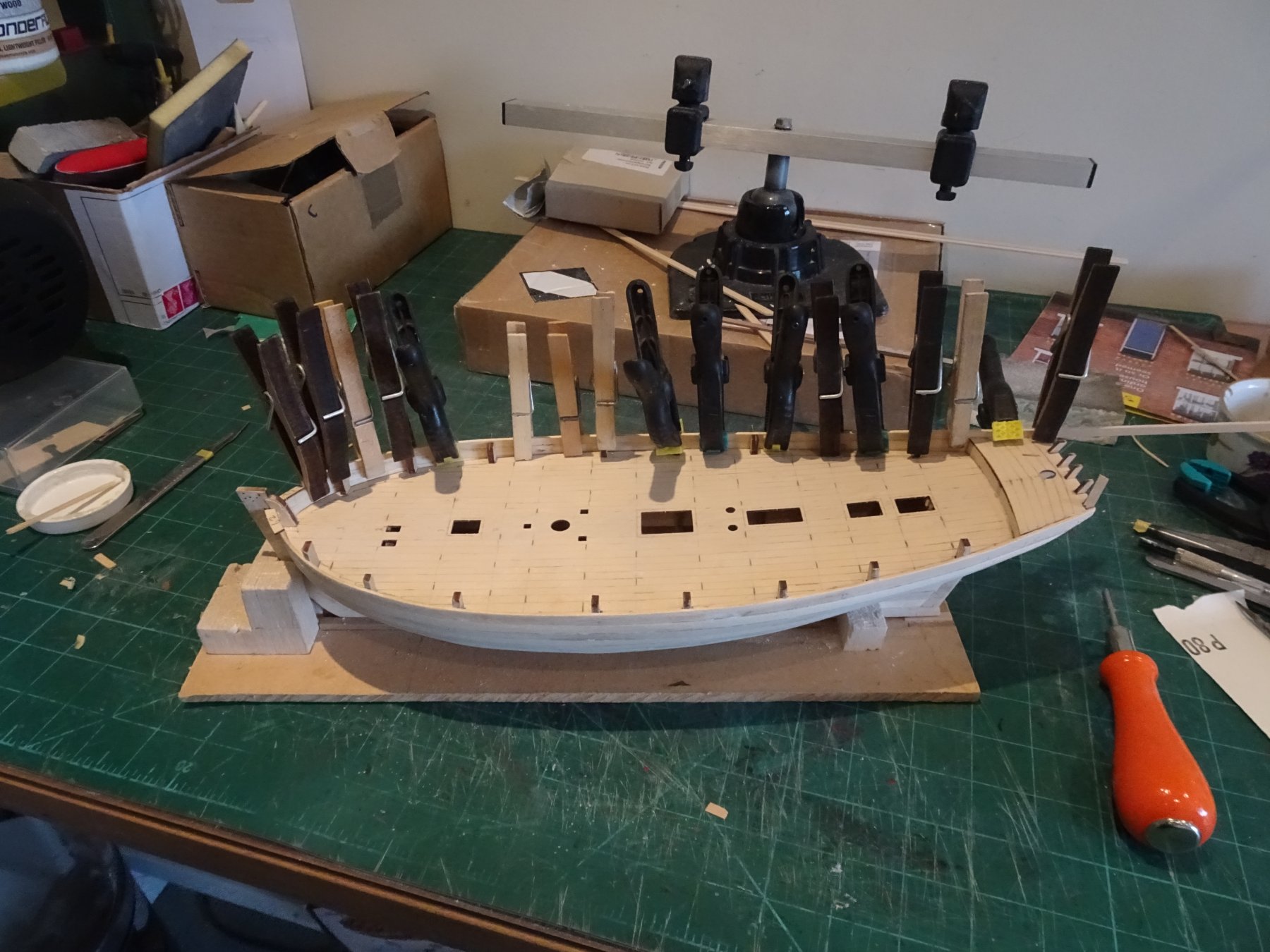
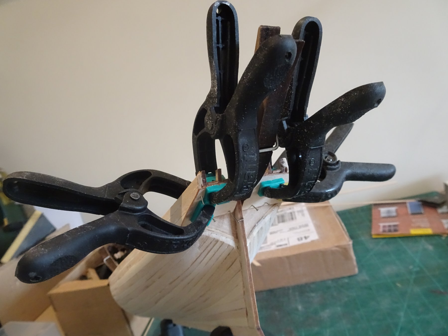
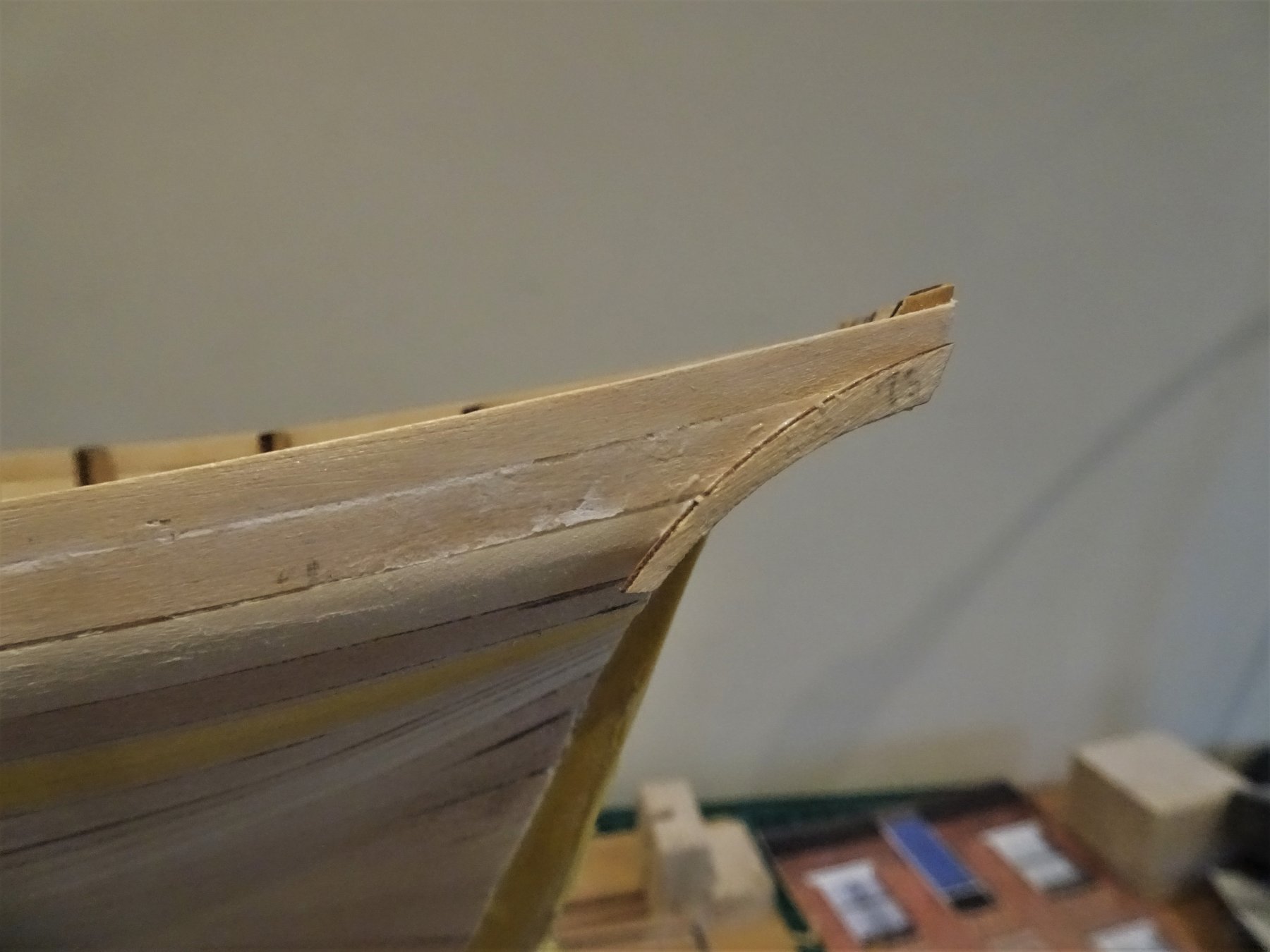
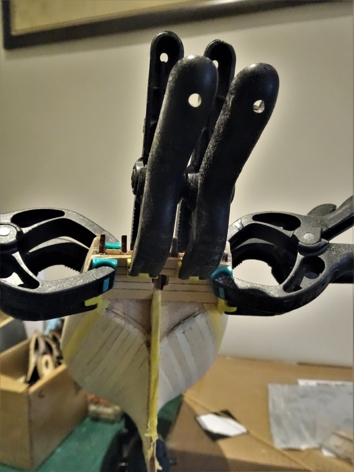
Post 9 Going off Piste - So to begin the next stage At this point things start to get interesting. I am departing from the kit arrangement of completing the second planking and then adding the wale. I need to add the wale at this point because below this level the planking is Clinker built, above the wale it is carvel. The lower hull planking will start at the garboard plank because below the wale the planks overlap the one below. If I sound confident and knowing what I'm talking about - always remember - appearances can be deceptive, and there will be plenty of time for me to bail out and revert to a carvel hull. The Wale According to the Goodwin book Alert had a single plank wale measuring 15" broad x 5" thick. (6mm x 2mm) This correlates pretty well with the kit dimensions of (2) 3mm x 1mm planks, which allowing for the second planking, is spot on. Fixing the wales is one of the most critical parts of a build and it takes some time and adjustments to get it looking right to your eye. 1391 I used Tamiya tape to initially mark the position of the lower line of the wale, this again correlates with measurements comparisons between the book and kit drawings. 1380 I then add a narrow strip at the lower edge of the wale position, to use as a guide to fit the wale. Actually this was the same strip as I used for my Cheerful build, pretty close for sheer but obviously shorter in length. I am using 6mm x 1mm strips of Boxwood for the wales, each wale will consist of two layers to give a finished thickness of 1mm over the second planking layer. The top layer will have the butt and hook scarphs scribed into the surface, but these may not clearly show once the wale is blackened. 1377 The wales are shaped at the stern to allow for the lower stern side counter pieces. These I cut out from some broad Boxwood Strip using the kit part (76) as a template. 1384 They are temporarily pinned into place until the upper bulwark top layer planking is completed. I have followed the arrangement for these side timbers as indicated in the Alert Book. 1378 A funny angle but the photo shows the curve of the side counter pieces to follow the wale line. 1383 Moving on... B.E. 01/08/2019


- 335 replies
-
- 17
-
-
- alert
- vanguard models
- (and 1 more)
-
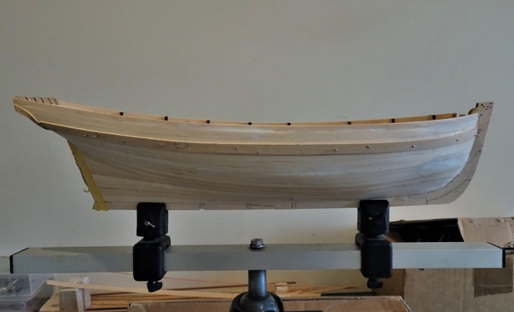
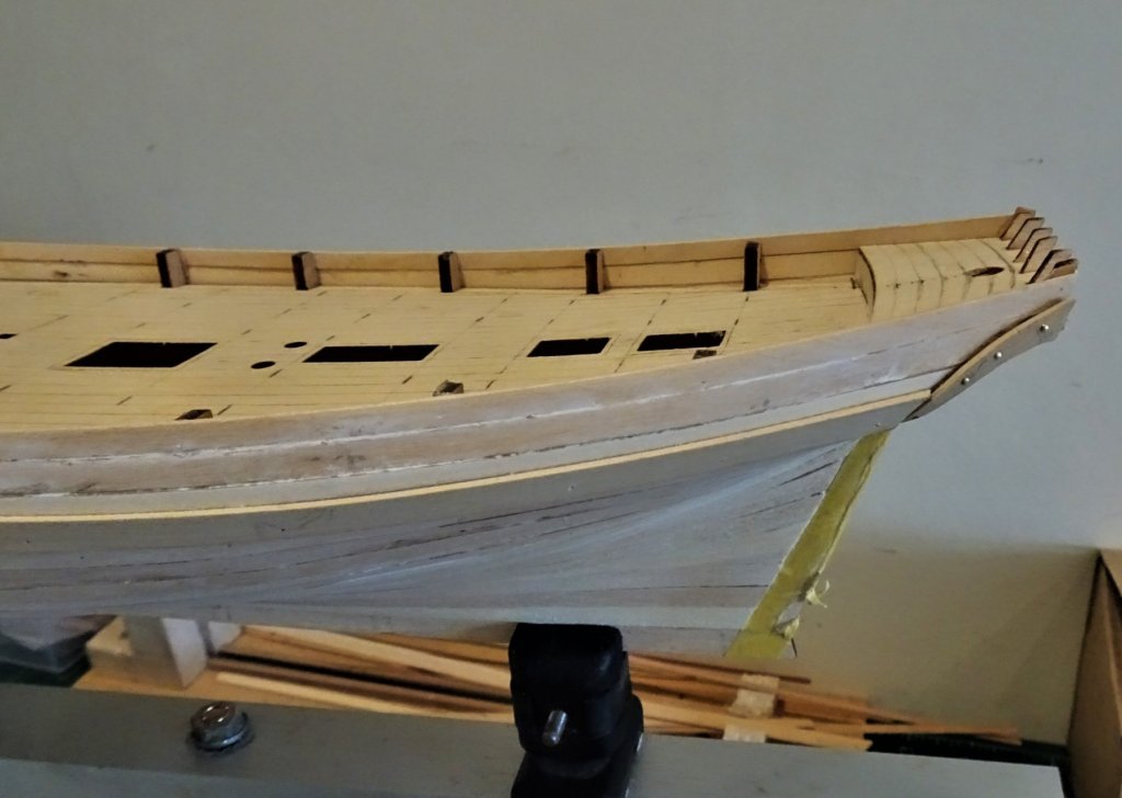
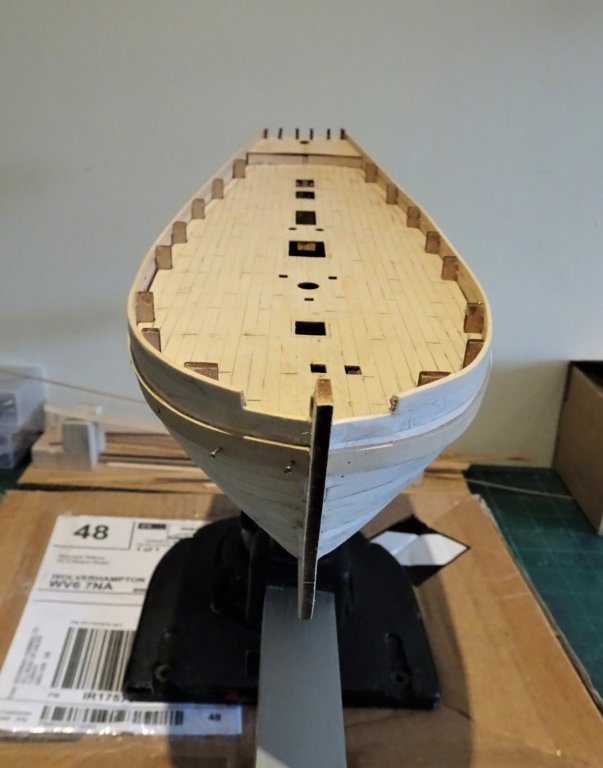
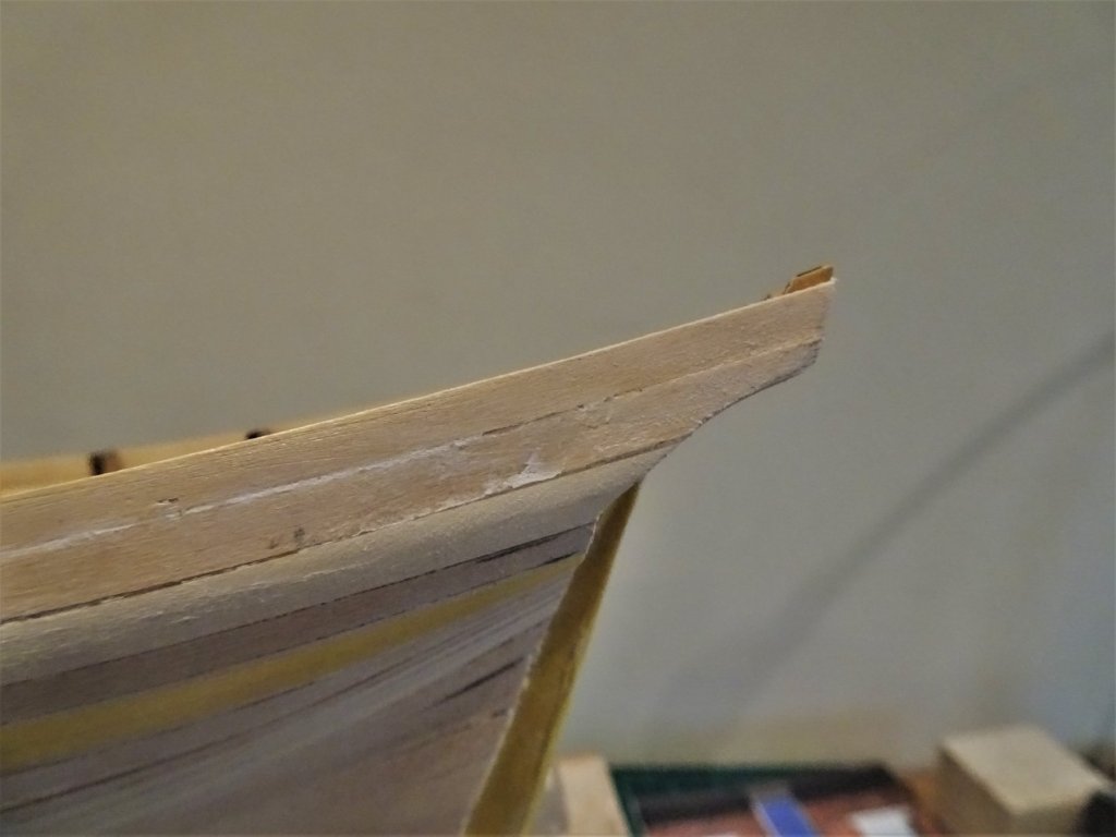
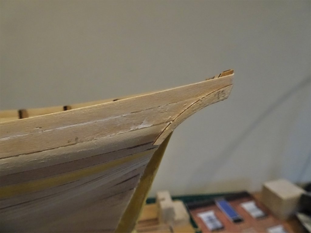
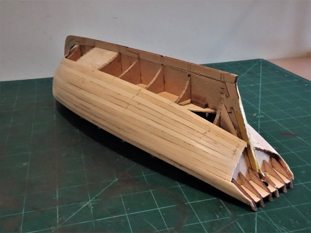
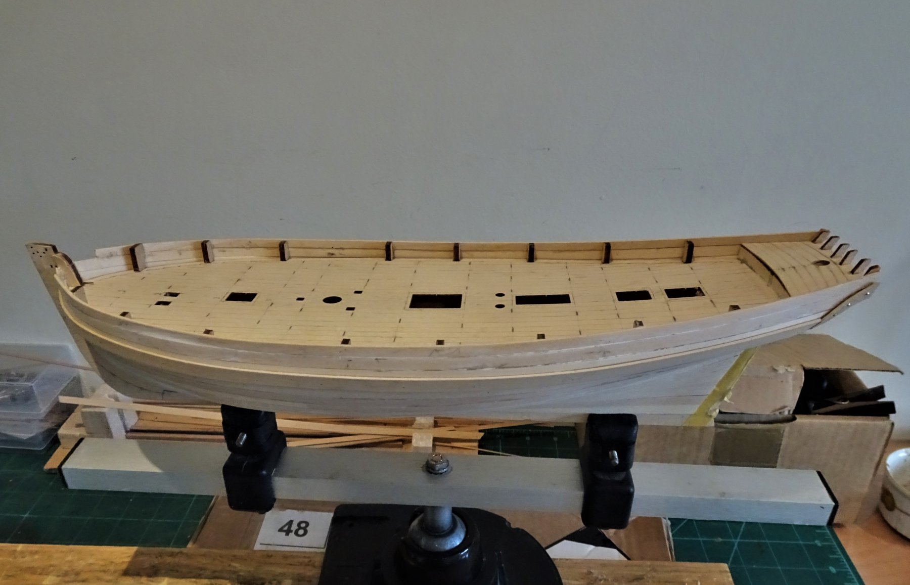
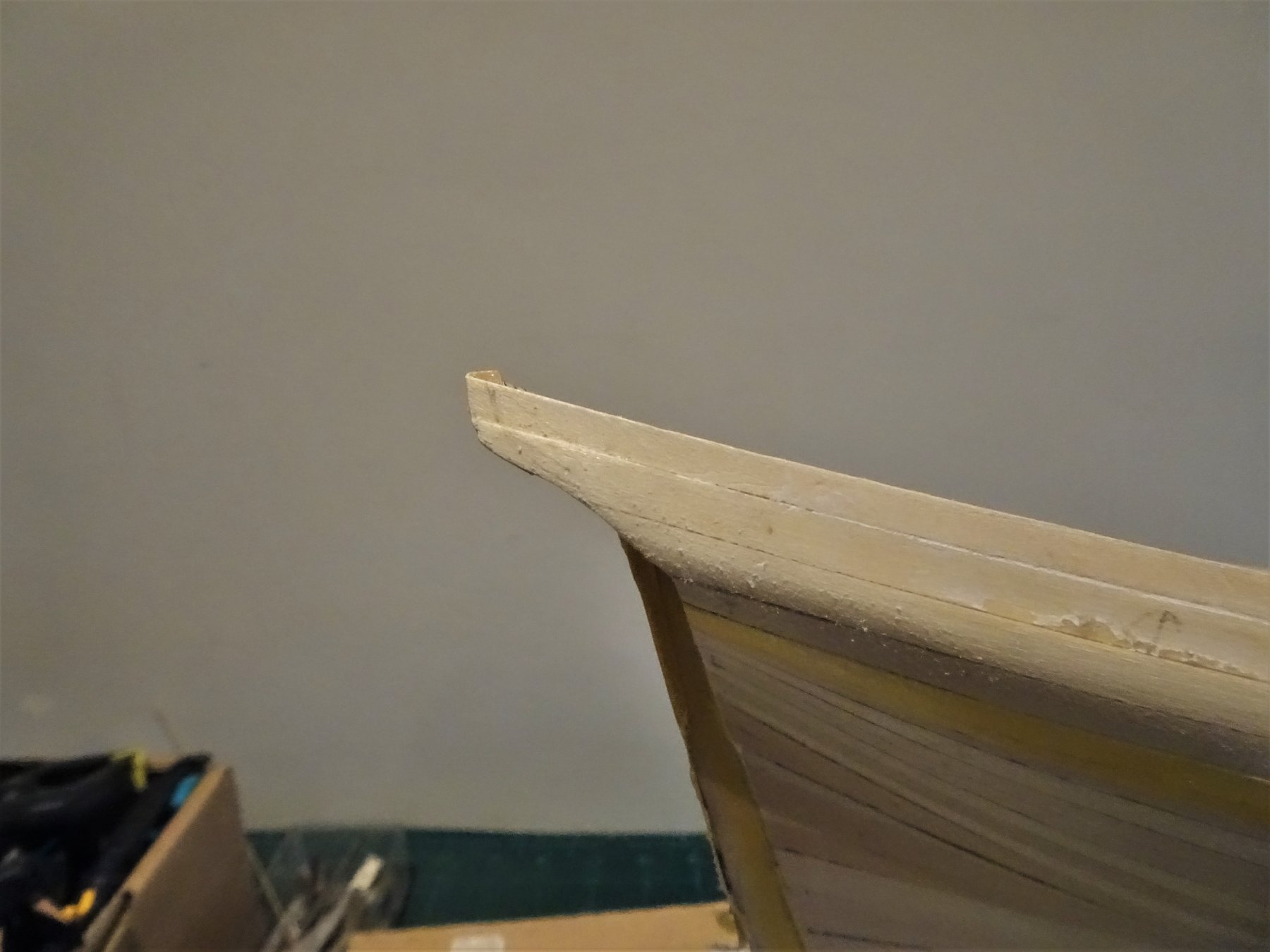
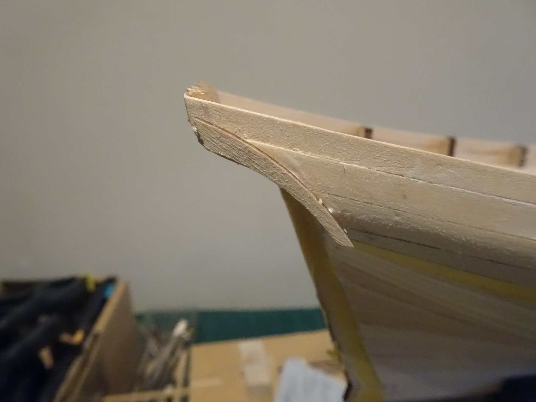
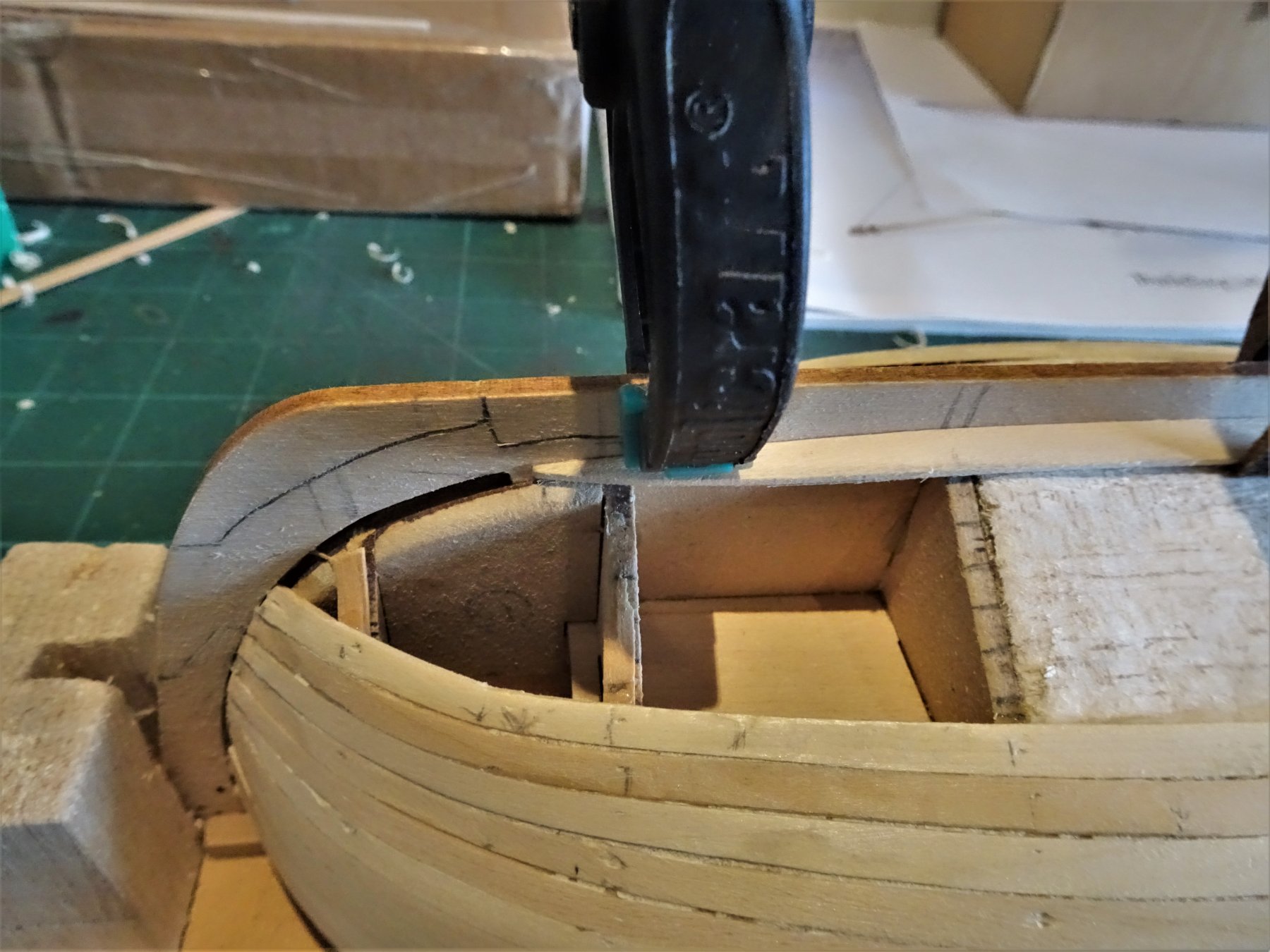
Post 8 Sand, fill, and the tweaks begin The hull has been filled where necessary using a very light and fine filler, sanded, smoothed, and sanded again. I used a thin vertical strip to highlight any hollows. My hull wasn't in bad shape prior to the sanding but I found that Chris's estimate of an hours' work for the sanding process to be somewhat optimistic in my case.🙄 1338 At this point I added the uppermost strake of 1.5 x 4mm strip. 1340 Using a full strip I formed a lateral bend to follow the sheer line and a slight curve to round the bow section. Went on quite easily but pinning thro' the upper end of the bulkhead extensions did split many of them. Clamps and pegs were used to secure the strakes during gluing, don't think pins are really required. Counter pattern (48) 1341 When I first fitted this I wasn't happy with the result, and removed it. It seemed to lack that graceful curve following the line of what would be the lower stern counter timber. This is because the stern frames are straight on their underside rather than concave. This is clearly evident on the kit build photo's which show it as a near straight line, which creates a mismatch to the curve of the lower counter pattern represented by part (76) In my opinion this produces a less than desirable look. 1343 Before fitting the counter pattern I would suggest that the curve of part 76 is marked on the stern timbers and the curve sanded into the profile, as shown above and below. 1344 1346 The lower counter pattern (76) temporarily in place. 1347 This is the effect I'm looking for. 1349 I then re-attached the Counter pattern (48), Note: I have left planking the tuck until later, I want the diagonal planking to go over the ends of the second planking rather than the other way around. 1357 With the counter in place I planked it horizontally with thin Box strip. I will probably replace the counter timbers with Boxwood versions. I note a difference between the kit Alert and the book Alert in that the lower stern counter timber on the kit version ends atop the wale, whereas the book drawings show the timber carrying down with the wale butting against it, in the same manner as Cheerful. This is something else I will need to consider when fitting the wale. B.E. 31/07/2019


- 335 replies
-
- 13
-
-
- alert
- vanguard models
- (and 1 more)
-
I'm leaning very much towards having a go at tinkering with clinkering 😃 B.E.
- 335 replies
-
- 4
-
-
- alert
- vanguard models
- (and 1 more)
-
I think we find there is much more to any build than we first thought Dave, but part of the fun is driving ourselves mad trying to get it right.🤔 I did take some liberties with the first planking , there's nothing like doing single planking with expensive timbers to concentrate the mind. 😃 Regards, Maurice.
- 335 replies
-
- 3
-
-
- alert
- vanguard models
- (and 1 more)
-
You're making good progress mugje; Acetone is the stuff to use to remove ca. I apply it carefully with a cotton bud but be careful it will also remove the plates if it is used too liberally. I follow up the cleaning using a mixture of vinegar and salt rubbed over the plates, be careful not to snag them. The plates will need to be fully clean if they are to age evenly. Regards, B.E.
-
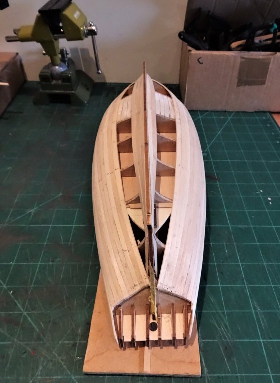
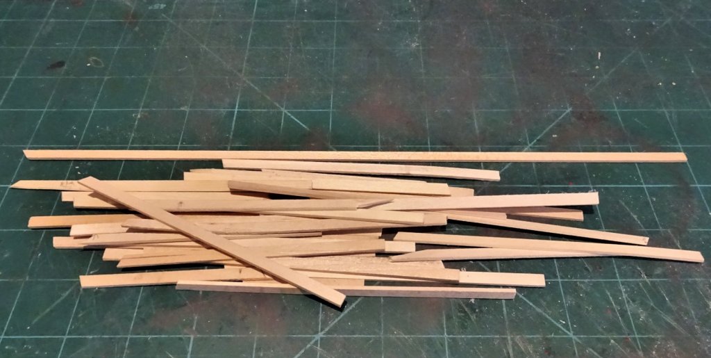
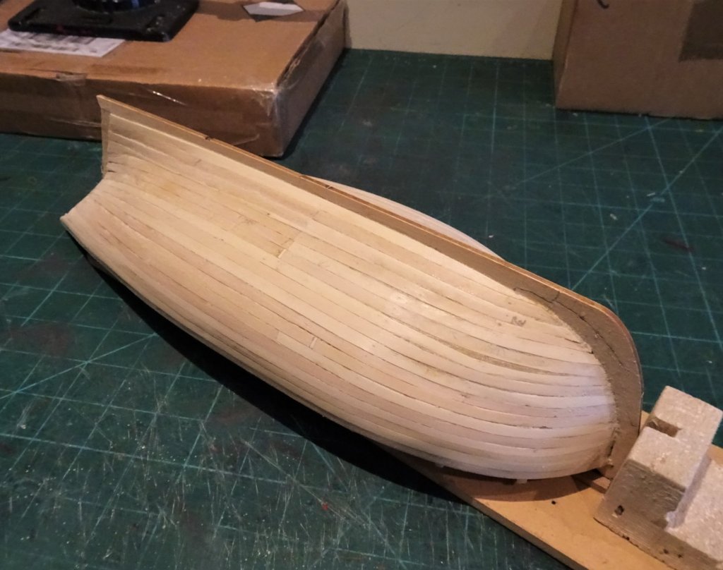
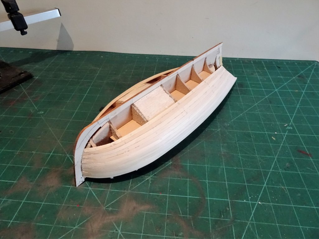
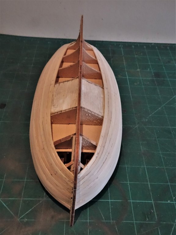
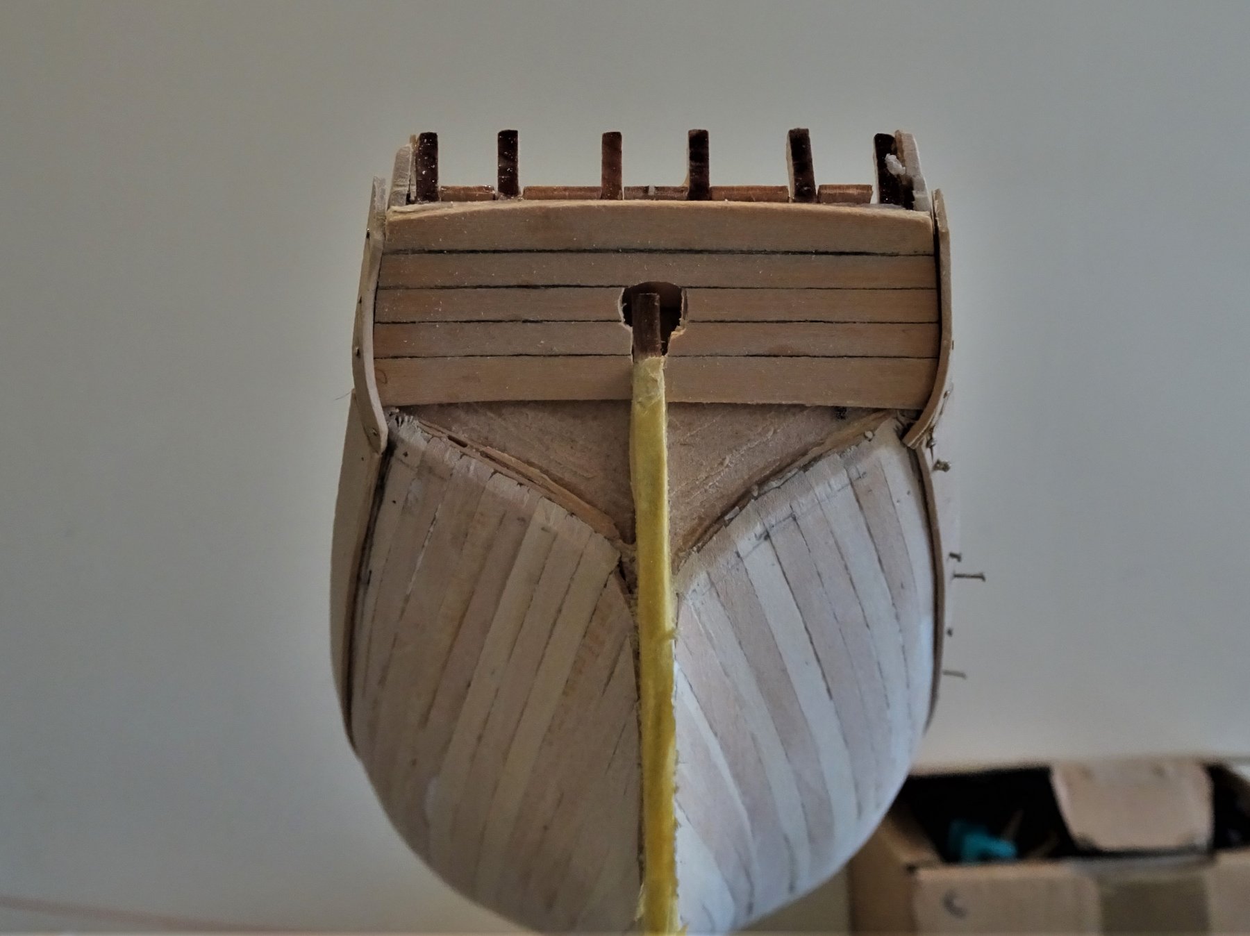
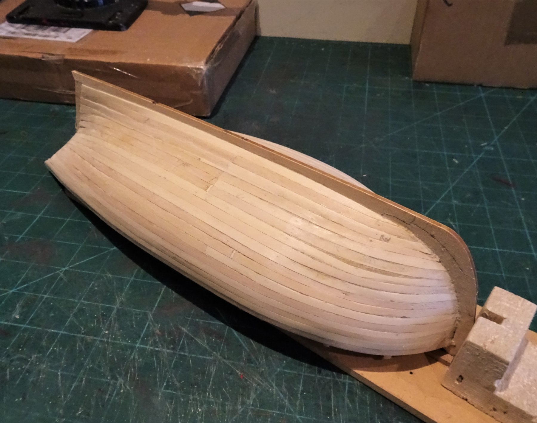
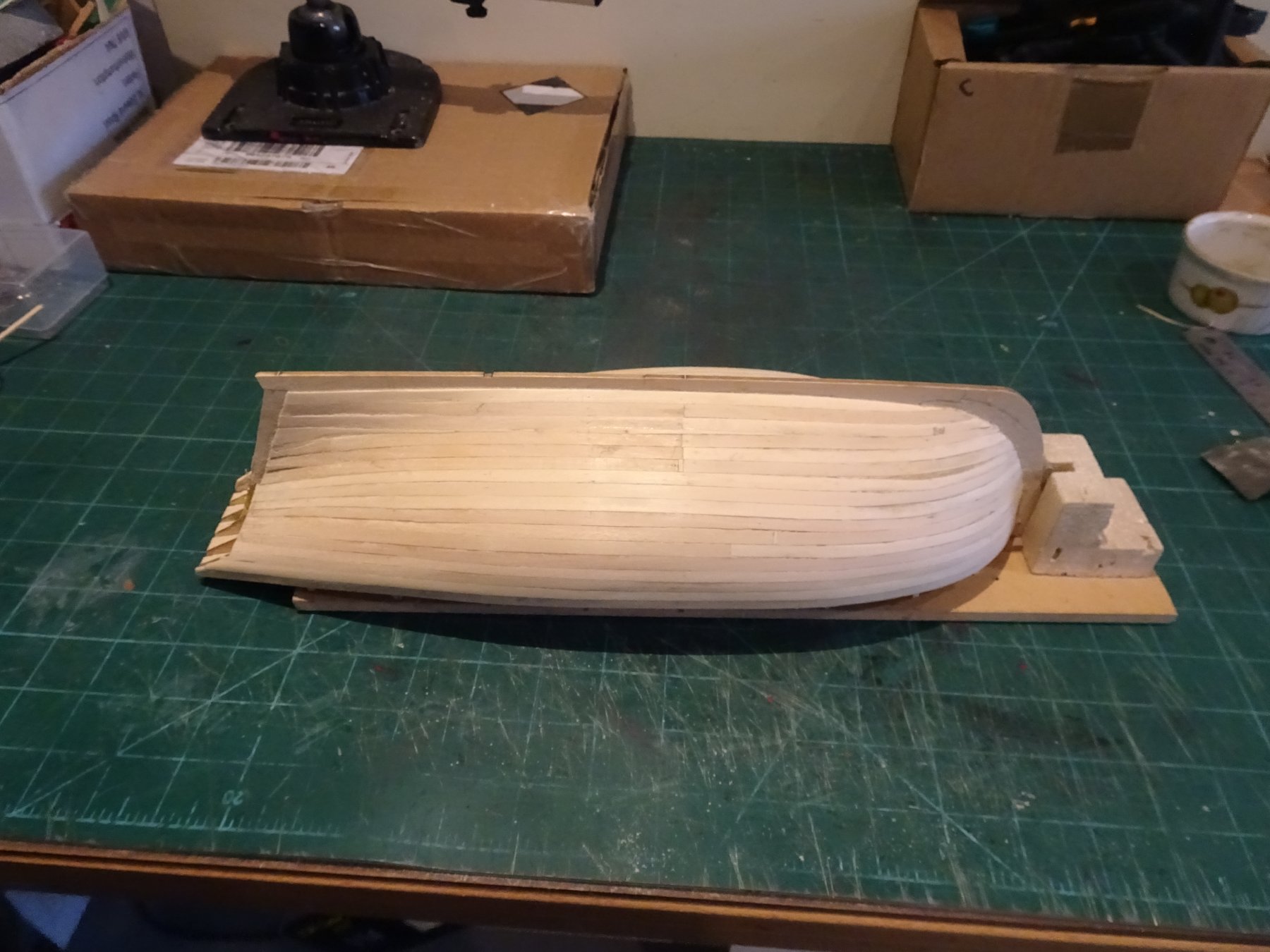
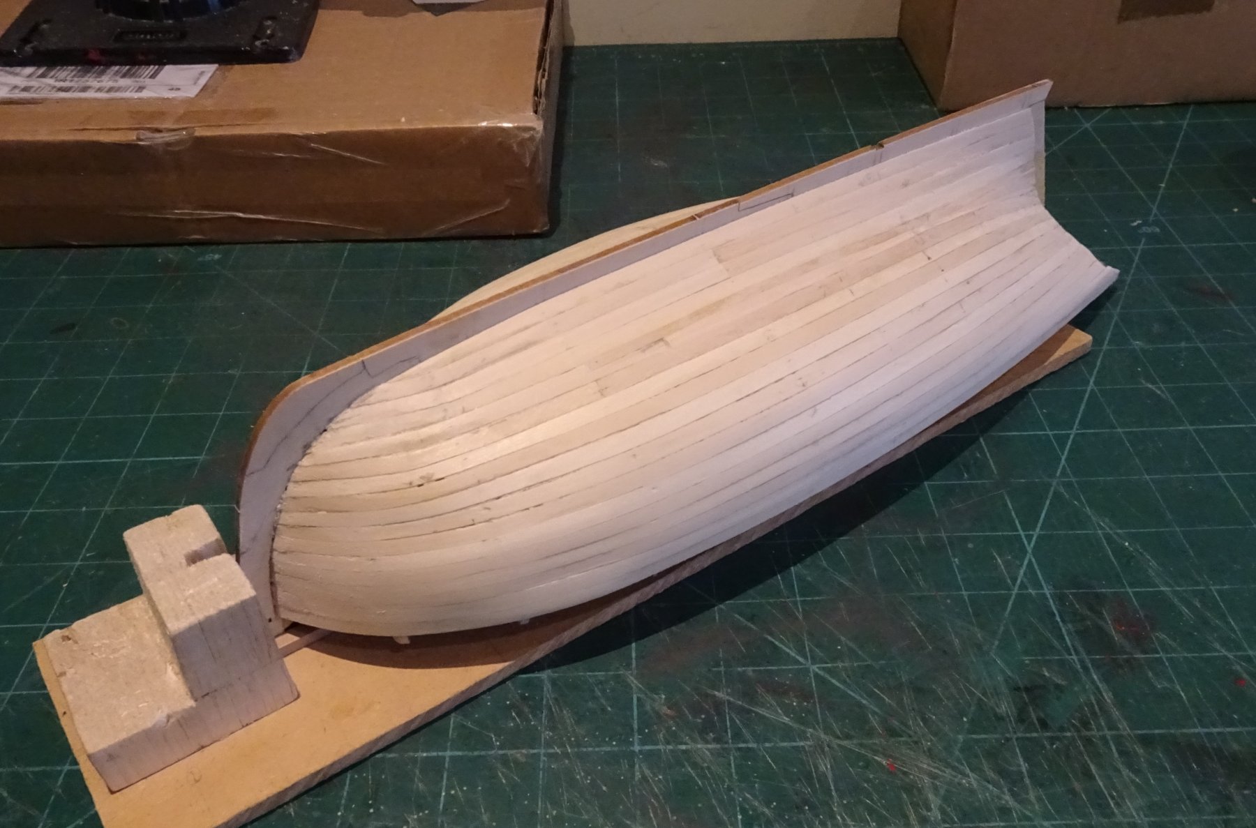
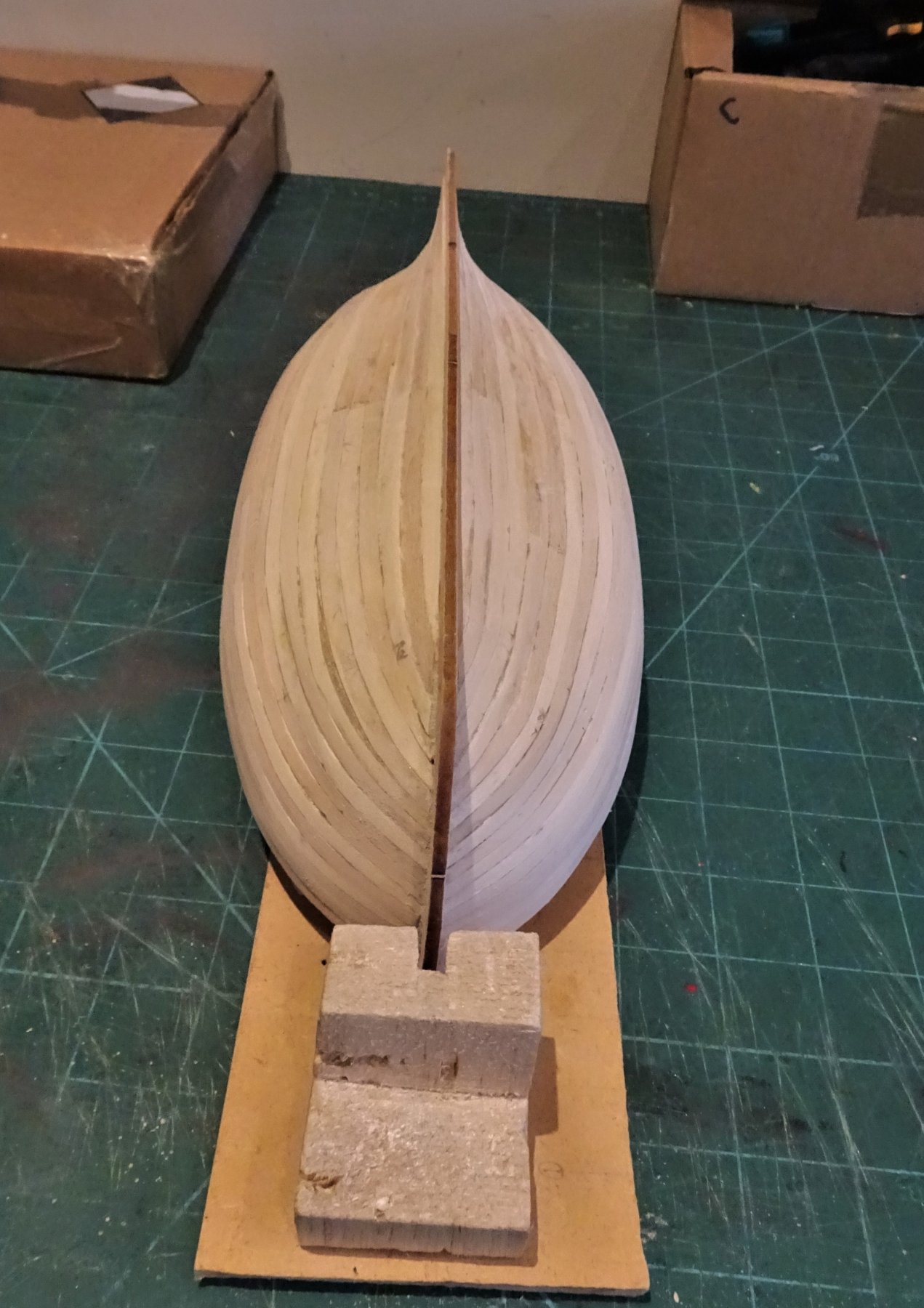
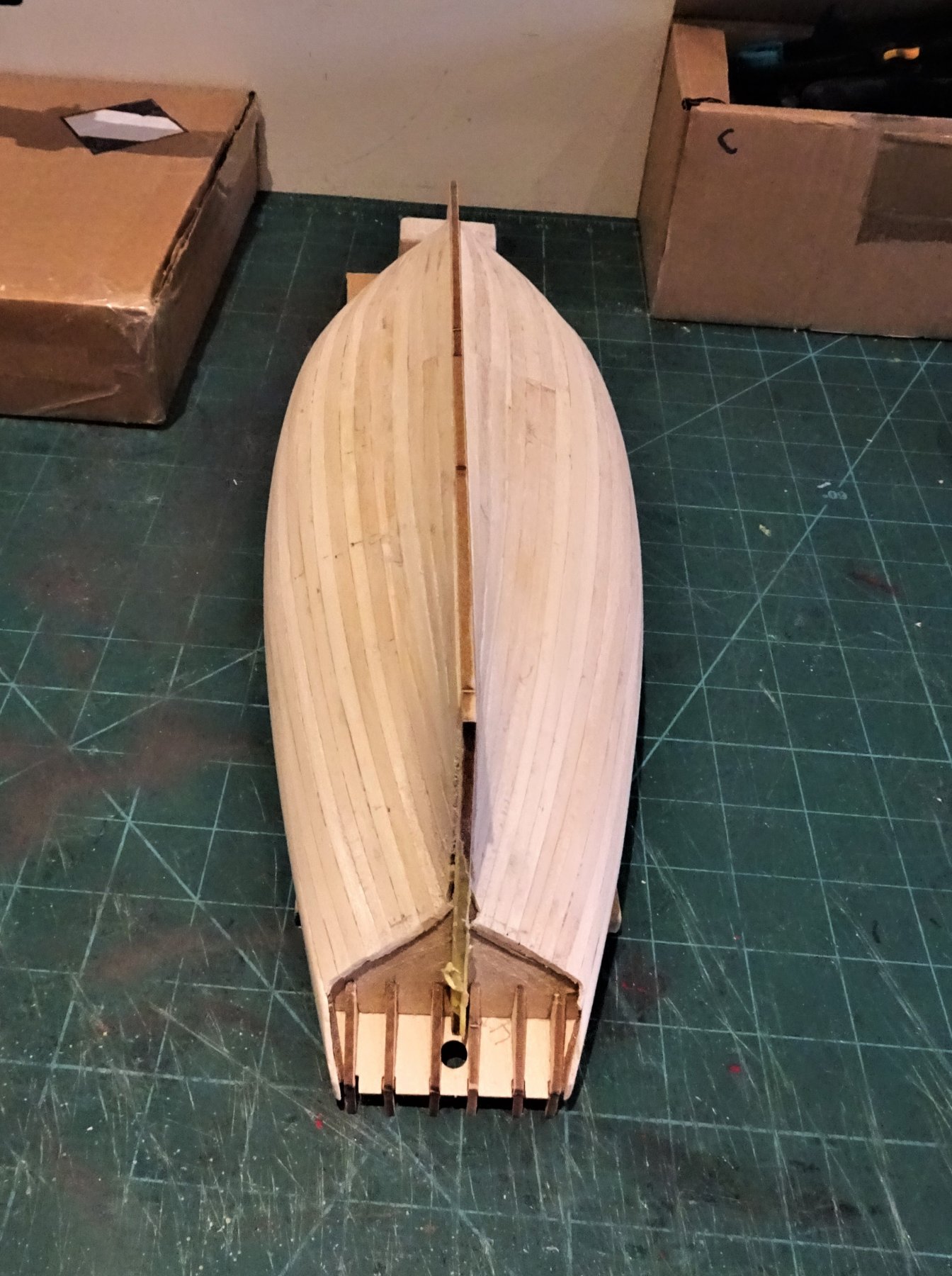
Post 7 Moving onto the Garboard Plank Back in the Boatyard I now invert the hull to start with the Garboard plank. On this kit with two plank layers it's not really necessary as the purpose of the first planking is to provide a solid and properly shaped hull form onto which the second layer is glued. However, the second layer will need to be properly planked for good effect so it does no harm to employ some of the techniques on the soon to be hidden first layer. 1169 The position of the Garboard plank at the forward end involves a little bit of best estimation. Because I have no rabbet the plank tapers to a near point at the bow end; I have it just forward of Bulkhead two and aft of the bottom end of the keel slot. 1171 The rest of the plank I have left at full width, but inducing some twist towards the aft end to allow it to lie flat against the false keel and stern post. If nothing else, fitting a specific Garboard plank will allow the correct position to be confirmed, and if it's a little out - well it will be covered up. I also bevelled the plank back edge where it meets the keel, and thinned it down a little on the back face where it runs into the stern post. Even so, a fair bit of thinning down will be necessary , basically down to nothing, to allow for the second planking. With the Garboard planks in place the adjoining plank is fitted. 1261 This quite a tricky one as there is a tight lateral curve at the forward end where it goes around the Garboard plank and into the stem slot. There is quite an acute angle to the plank end. I then add a third strake also requiring lateral bending at the bow end. 1264 To achieve the required bends the curve has to be formed at least a third along the length of a strip to get the required purchase. The Lime wood did not lend itself easily to the lateral bending process with breaks occurring at fault lines along the grain. I did suffer quite an attrition rate of breaking strips, a problem not experienced with hardwoods such as Box. This resulted in several of the strakes being made up of two planks butt joined. The final strip of a very irregular shape lies beneath the curve of the hull and was spiled to fit. Using the provided strip of all one width makes avoiding stealers almost impossible, but as a first layer base this is not really an issue. 1270 At the end of the first planking I am left with a pile of off-cuts. There is sufficient strip to do the job, particularly if you follow the suggested kit method of planking. So here is the completed first planking in all it's rough glory. 1272 1273 1274 1275 1276 The sanding process now begins, there are a few hollows and ridges to sort out before I move on. Then comes the really interesting bit. B.E. 28/07/2019


- 335 replies
-
- 19
-
-
- alert
- vanguard models
- (and 1 more)
-
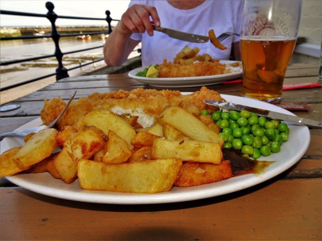
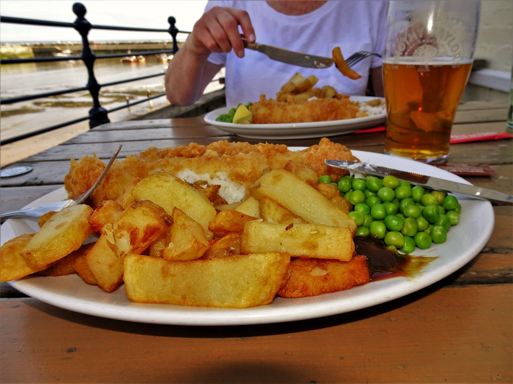
Thank you Kurt, North Yorkshire was wonderful and the weather was kind to us. Being retired, life is one long vacation for us, I am happy to say.☺️ 0976 .... and the Fish and Chips at the Cod and Lobster in Staithes were delicious. Glad we didn't order the large portion! Back to the Boatyard. B.E.
- 335 replies
-
- 9
-
-
- alert
- vanguard models
- (and 1 more)
-
Thanks Jason and Timmo 🙂 B.E.
-
Well done Timmo, a very fine model, and I love the way you have incorporated the plan into the base. 👍 B. E.
-
Good question Gary 😃 I haven't firmed up my approach as yet, but it will have to be done from the keel up, and certainly for a novice like me I think having a solid plank base to work off will assist the process. B.E.
- 335 replies
-
- 3
-
-
- alert
- vanguard models
- (and 1 more)
-
I agree with Chris about the Walnut planking on Pegasus, I discarded it on my build. I used thin 0.7mm Boxwood strip from Original Marquetry in the UK, not that expensive, and the bonus is it comes in different widths up to around 12mm I think. Well worth the investment for me. B.E.

-
Thanks Gary I’ll check that out 👍 B.E.
-
Oh do shut up Dave, you're making me feel ravenous . 😄 B.E.
- 335 replies
-
- 2
-
-
- alert
- vanguard models
- (and 1 more)
-
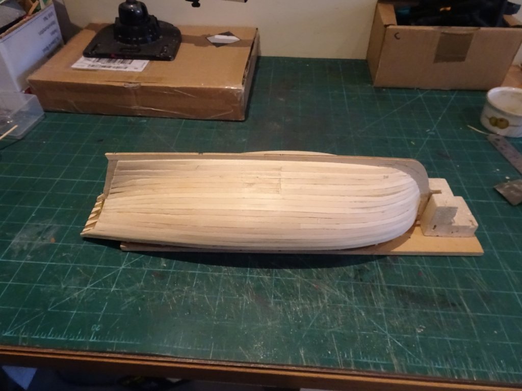
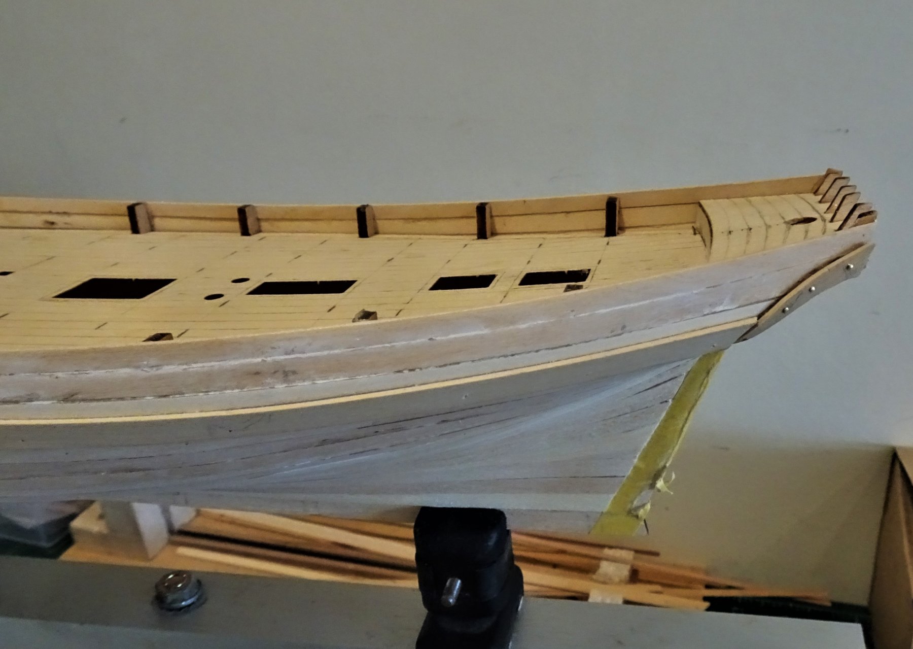
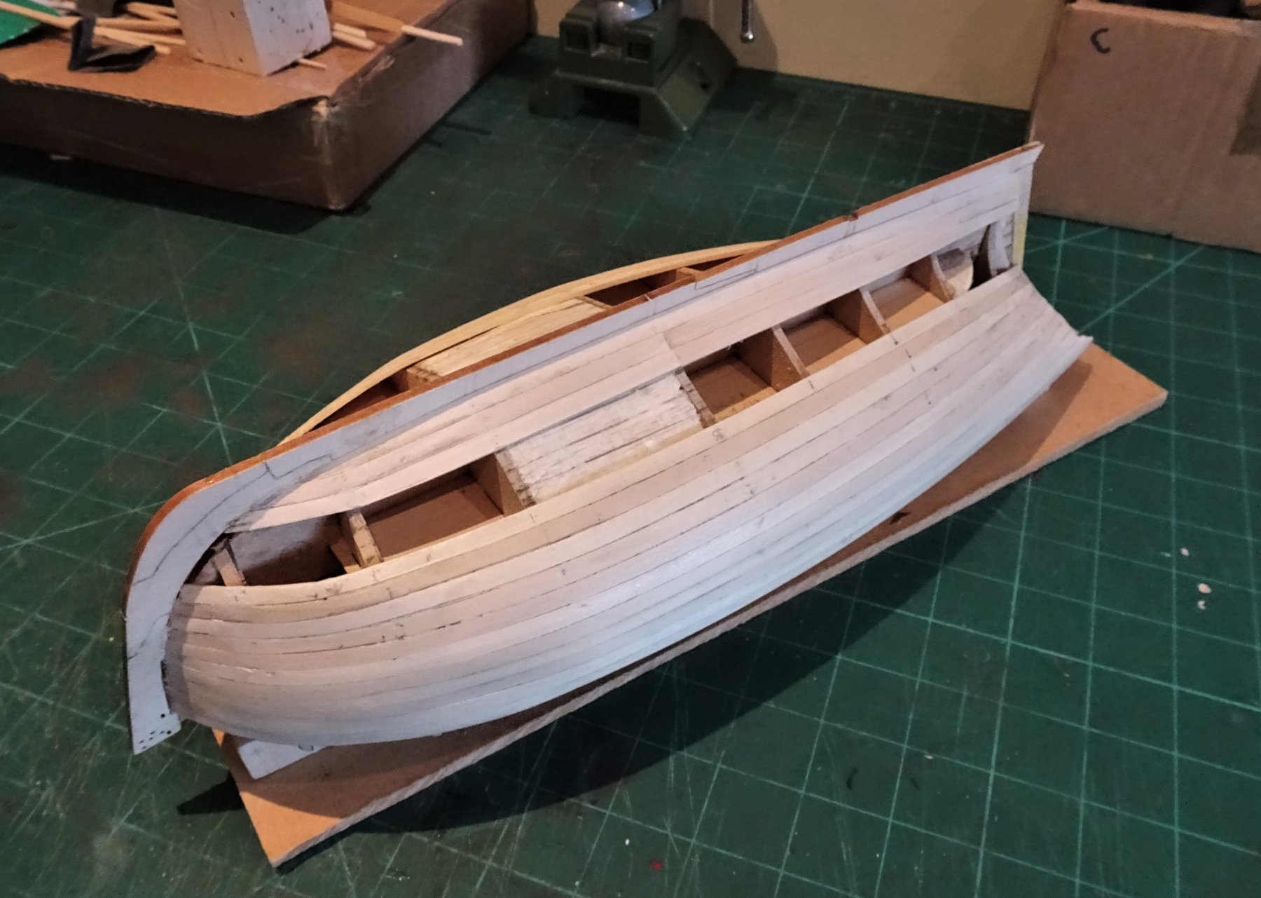
Post 6 Planking continues I have inserted a balsa filler in the lower hull between bulkheads 4 and 5 which has the greatest space, but I don't think fillers are necessary elsewhere. 739 I planked the hull down to the lower deck level, using a rule of thumb taper and bend method. Below this where planking gets tighter I lined off the hull into two bands, the upper of five strakes and the lower of six planks. 737(2) I used the tick strip method to determine the required tapers. 741 Once tapered water and heat was used to form the necessary edge bend and bow curve. 930 I have given up on trying to leave a space for the second planking in the stem slot, it just doesn't work for me. 931 I will work the remaining strakes up from the Garboard plank which will probably leave me with a spiled plank on the underside of the hull. 932 As with all such builds it is the bow area that is the trickiest, the run of planks to the stern is fairly straightforward. 933 This is the state after a light sanding, one or two lumps and dinks to fettle but I'll leave that until the planking is complete. The quality of the Lime-wood planks is good, and they take a tapering cut very well. I have twelve strakes left to complete and there will be three full lengths of first planking left when I've finished, barring any mishaps. I have scrapped a couple of lengths which snapped during the bow bending operation and another couple due to mis-cuts, but I am left with a small pile of shorter lengths which would come in if push came to shove. I rarely enjoy this first stage of a build, but I know from experience that it will come right once the sanding is completed. On the subject of first planking it is refreshing to see that Chris has chosen to show in the build manual, the hull in all its roughness with ridges and hollows and clinkering, the point at which many new builders look and think Blimey, will this ever look right? - yes it will with careful finishing. 797 The shipyard is now closing for a week whilst we head up to North Yorkshire, looking forward to those fish and chips at the Cod and Lobster in Staithes. B.E. 11/07/2019
.thumb.JPG.83dd4ac6bd071ca76929600e0cd7b20b.JPG)

- 335 replies
-
- 21
-
-
- alert
- vanguard models
- (and 1 more)
-
A very fine model Mark, congratulations and well done. 👍 B.E.
- 652 replies
-
- 2
-
-
- royal william
- euromodel
- (and 1 more)
-
I would agree with Peter, the rectangular shape of the light is a per the Swan drawings and other examples I have seen. It would be quite authentic to see boards behind the glass panels. These features were more ornamentation than practical purpose, and even on larger vessels with quarter galleries, some of the lights were dummies, there for purely aesthetic reasons, and sometimes blanked out for privacy. B.E.
- 467 replies
-
- 1
-
-
- fly
- victory models
- (and 1 more)
-
I have eleven ship models around the house in scales ranging from 1:150 - 1:24. Different scales and subjects do allow for more display options, if I built everything I have in 1:48 scale I would have a wonderful collection of models - but no wife! B.E.
-
The instructions indicate that the front of the plank is fitted into the slot in the bow pattern which is what I did having pre-bent the plank to fit around the bow, with the ends 50% into the slot each side. I did cut a small rebate in the plank end to reduce the thickness at this point. I still found that I needed to brace the plank against the aft edge of the pattern by inserting a strip between it and the forward edge of the pattern, until the glue set; otherwise the natural inclination of the plank is to hold against the forward edge of the bow slot. B.E.
-
Perhaps it's me then Chris, 🤔,or perhaps my particular stem piece had a grain line in just the wrong place. As far as medium choice is concerned I do generally agree with you that mdf would restrict those who prefer to varnish rather than paint. I intend to paint this one, (I have Cheerful as an unpainted Boxwood model) My worry was that the stem would break at a point of no return with some of the planking in place. I do have three strakes in place now and I think the further down the stem I go the less stress on it there will be. It is clear to see even at this stage she does have very nice lines.🙂 Regards, B.E.
- 335 replies
-
- 1
-
-
- alert
- vanguard models
- (and 1 more)
-
Fortunately Dave there is not a lot of dust involved, just from the fairing of the bulkheads, I do wear a mask tho'. It's the cutting out of all the basic parts from sheet stock that I prefer not to do, you'll no doubt be relieved when you have all the parts ready for construction. Cheers, B.E.
- 335 replies
-
- 1
-
-
- alert
- vanguard models
- (and 1 more)
-
Hi Steve, No, the grain runs horizontally across the stem. The weak point is the small section aft of the slot, that is glued atop the false deck. Any pressure put on the stem by the first two planks during fitting will find the fault lines in that area. In the absence of a quality wood like box I think MDF would be a preferred option. B. E.


.JPG.d9337d8443d73d39708f35a1b9c2a682.JPG)