jack.aubrey
-
Posts
1,268 -
Joined
-
Last visited
Content Type
Profiles
Forums
Gallery
Events
Posts posted by jack.aubrey
-
-
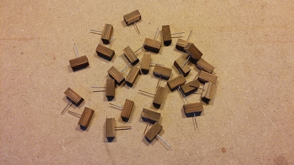
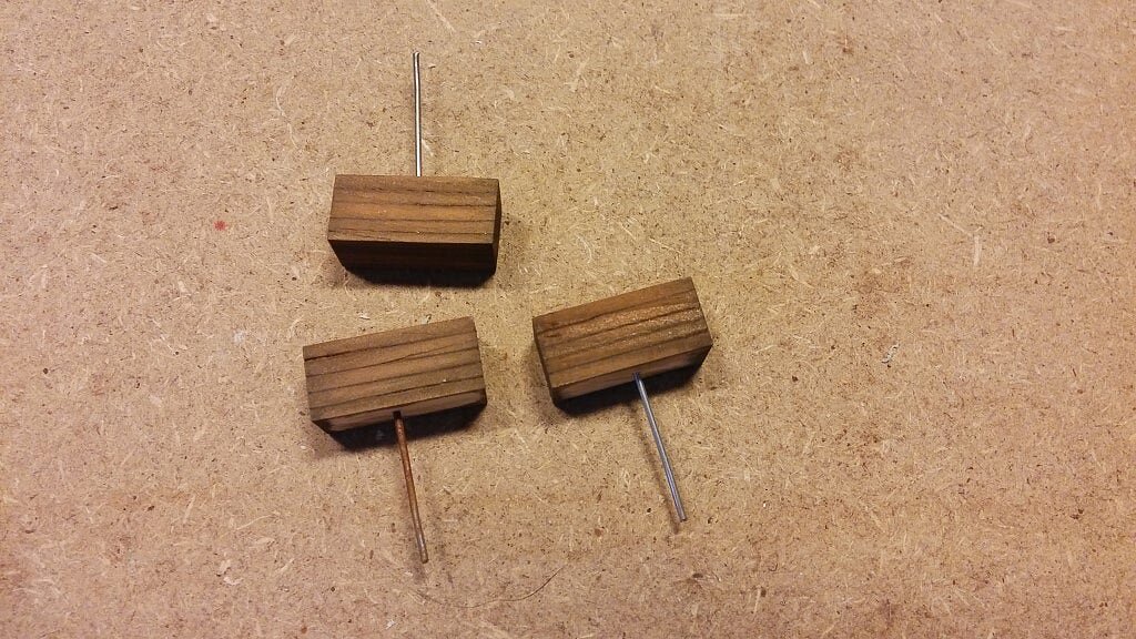
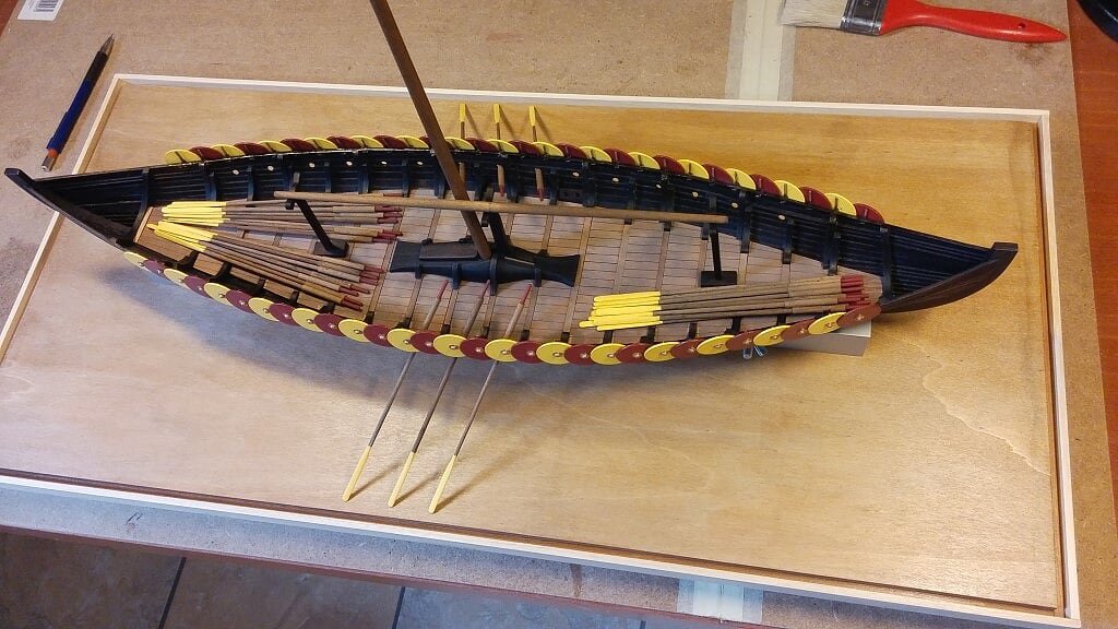
My attempt to model the seats for the oarsmen.In practice this is the famous "sailor's box" where the owner kept his personal belongings with a blanket added over its cover to soften the sit. When the ship run with sail the whole was stored under the deck planking.
01 20160724_113853.jpg
02 20160724_113916.jpg
03 20160724_122339.jpg
 Here below the reference image for my idea. .04 Viking ship with seats_zpsbw6yliot.jpg
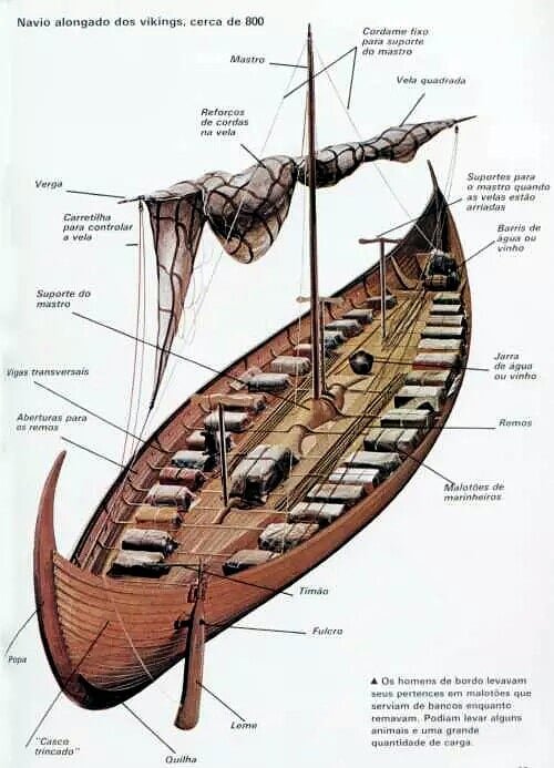
- gjdale, Daniel Dusek, dashi and 8 others
-
 11
11
-
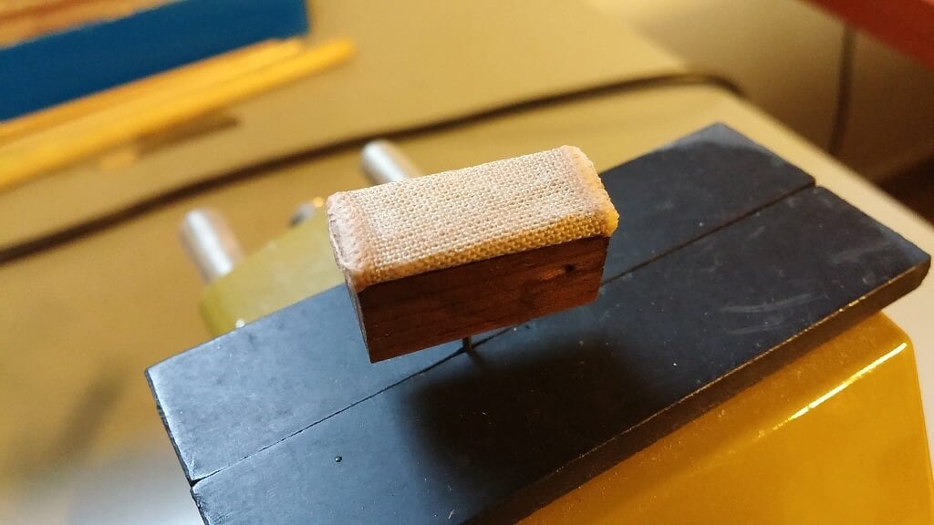
In effect I'm working to build the seats for the oarsmen, they are 50% ready, I only need to find a way to realistically simulate the kind of cushions or covers over the boxes, as shown in the following picture . .

- cobra1951, Seventynet, Canute and 1 other
-
4
-
Saturday, July 23, 2016Positioning test to verify if the size of the basement is right . . . Well, the oars are there, then the size is right.
01 20160721_171027.jpg
02 20160721_171035.jpg
03 20160721_171022.jpg
04 20160721_171010.jpg
Today I painted the basement frame, the underlying pins and the keel holding blocks with an acrylic dark red paint.
Finally I glued in the final position the two blocks with a bi-component epoxy glue.
Now only the plexiglass is missing to complete the display case, but I have to wait 'cause I need to install the mast to define the correct height of the case.
-
Hi Jack, I just want to say what a beautiful job you are doing on the Gokstad. I have been building the same kit for the last week and I find I am constantly turning to your log to see how you've done things. So I really appreciate your step by step details. I hope you also show the rest of your plexiglass showcase construction as I have a few I need to build.
One area that slows me down is how to finish the planks at the bow and stern. When you look at the reconstructed real ship it is evident that they carried the clinker plank overlap right to the ends. I think that's how the clinker system is supposed to work. So far (first 4 planks including the garboard) I am ending the overlap a few centimeters before terminating the planks so that they are edge to edge as they seat into a rabet that I cut. The way the final ribs are cut doesn't seem to invite the planks overlapping at the ends.
Anyway beautiful job!
Regards, Ian
Hi Ian, first of all many thanks for your appreciatons . .
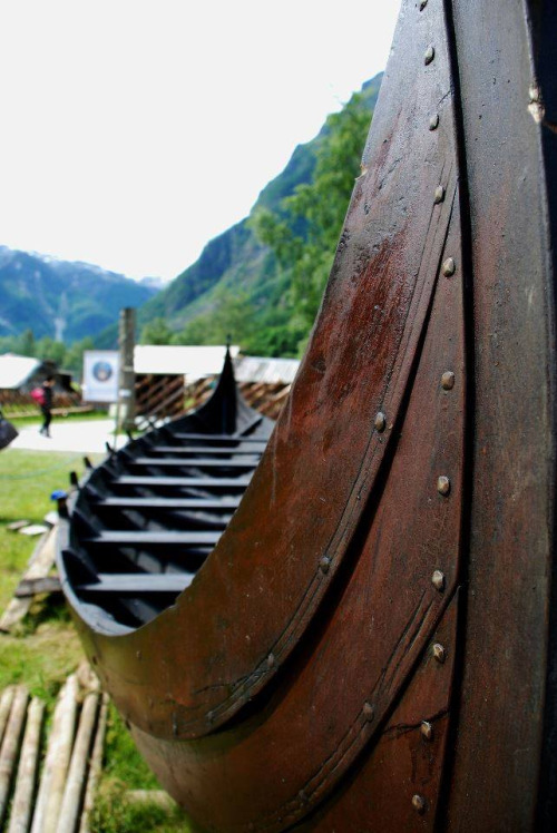
Regarding the planking at bow and stern I'm still a little bit confused. My understanding is that at the end the planks seem not to overlap but are gradually aligned edge to edge.
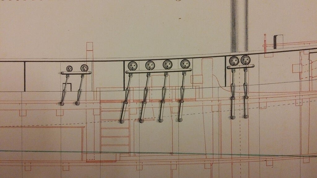
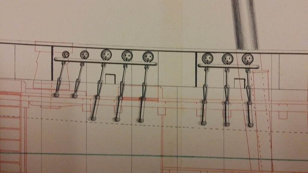
The following image shows what I mean probably better that thousand words.
What I don't have clear is HOW they got this result . .
- aviaamator, dashi, Seventynet and 3 others
-
6
-
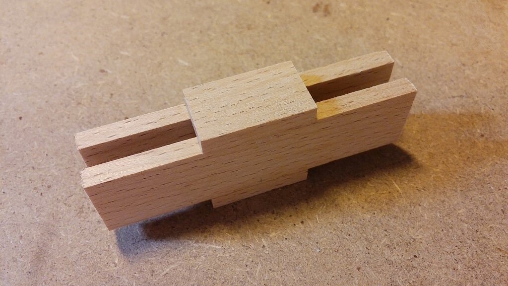
A complex piece made with hard wood from which I got the two brackets to support the hull. They will be placed over the display case basement.
01 20160721_171347.jpg
02 20160721_171328.jpg
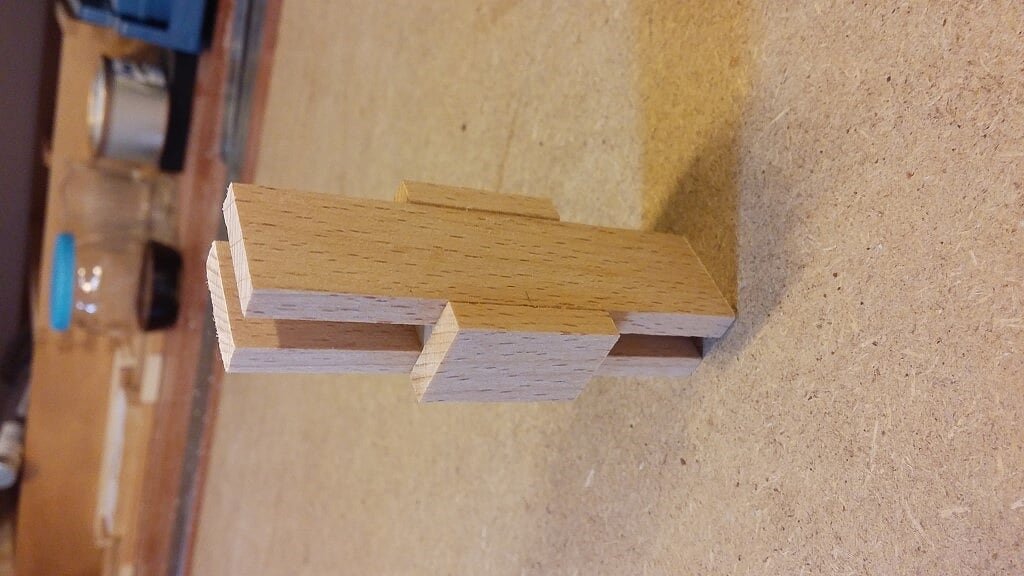 With a cut made in the right place, done with the yable saw, I got the two pieces shown here below which will hold the keel on the basement shown in the previous message.Now I have to drill them to accommodate the keel holding screw.Then I'll paint them dark red (same color of the shields).To be finally fixed on the basement in the correct position.03 20160721_173417.jpg
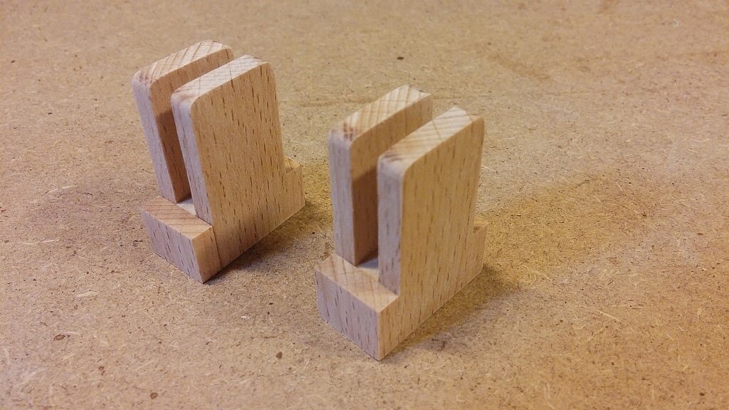 Cheers, Jack.My personal assistant to check the proper progresses of my work in its strategic role as project supervisor . .04 20160718_182026.jpg
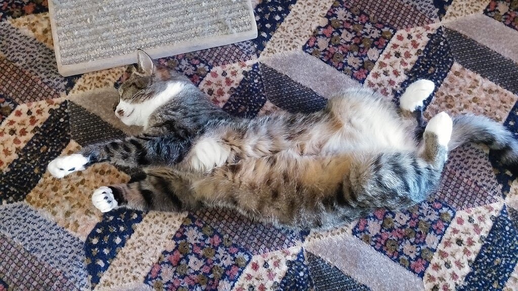
-
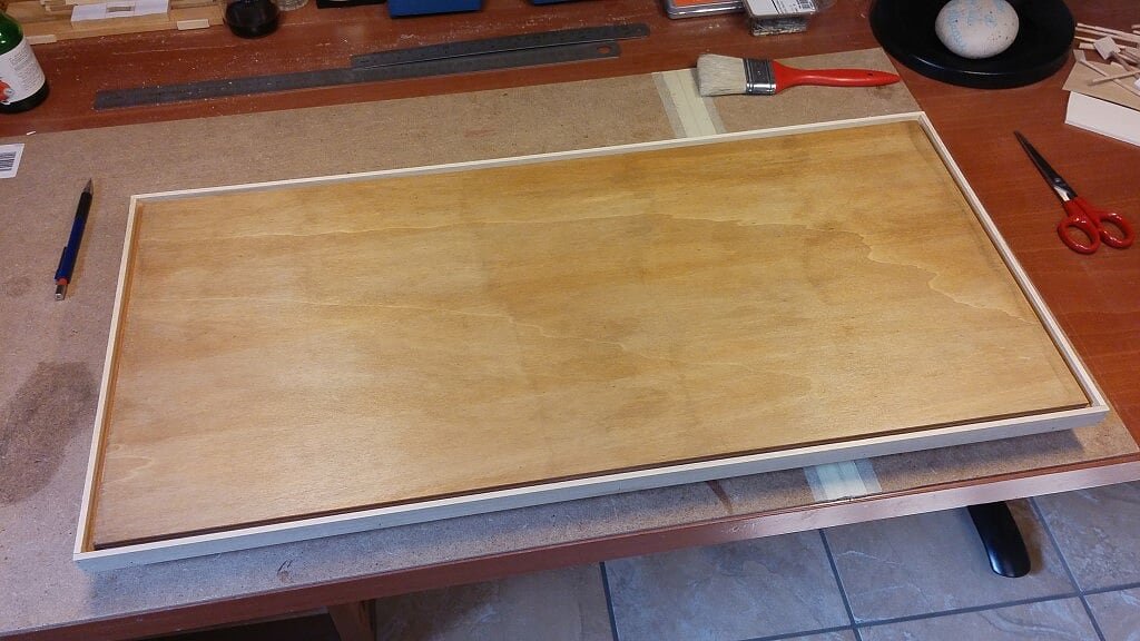
Thursday, July 21, 2016Started the tasks to build the display case basement, to be completed, at the end, with a plexiglass cover . .
The basement seen from its natural position: stained with a chestwood colored solution, the groove to hold in the plexiglass cover ready, with the outer frame that will be painted with the same dark red colour I used for the shields.
01 20160721_171211.jpg
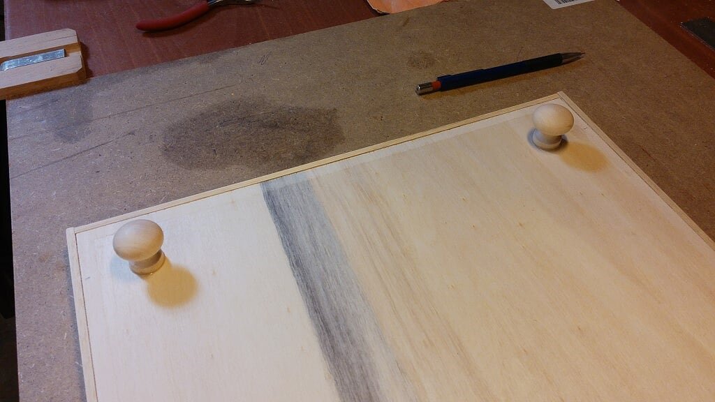
The lower part of the basement, with four wooden "feet" already added, to be painted dark red too.
02 20160721_171237.jpg
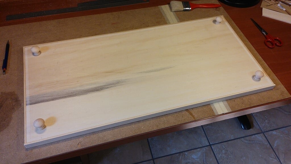
A detail of the four lower feet (is it the right term ?): I used simple knobs for drawers, easily available in DIY stores. I used a two-component epoxy glue, enforced with an internal metal pin.
03 20160721_171229.jpg
- Cathead, Daniel Dusek, dashi and 4 others
-
7
-
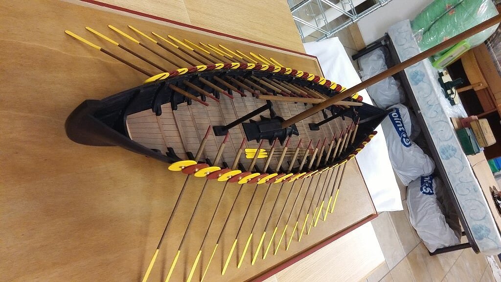
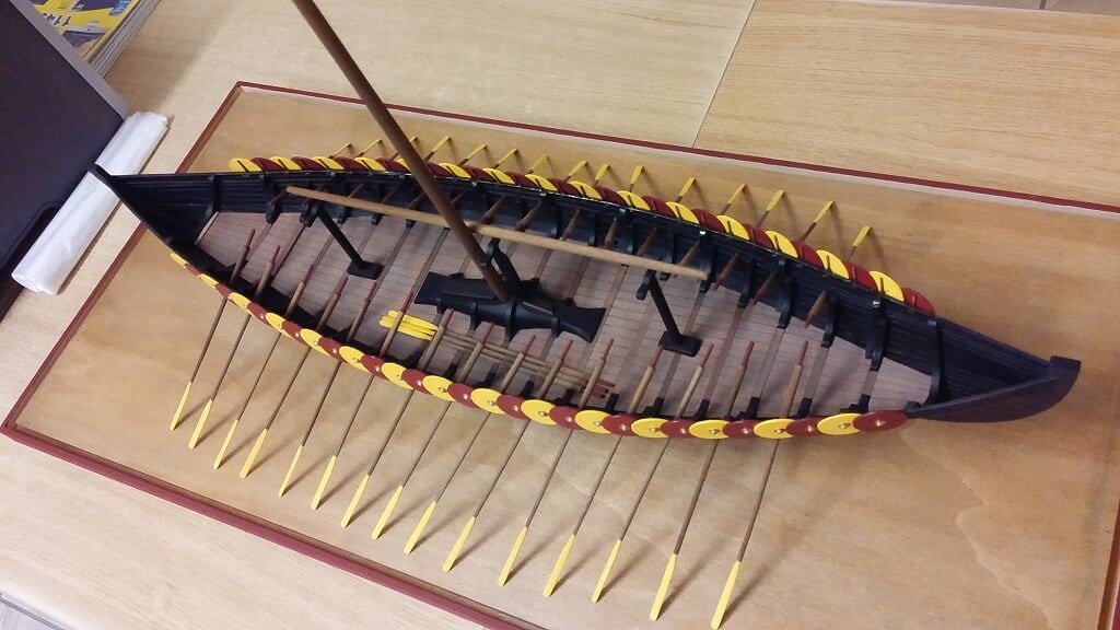
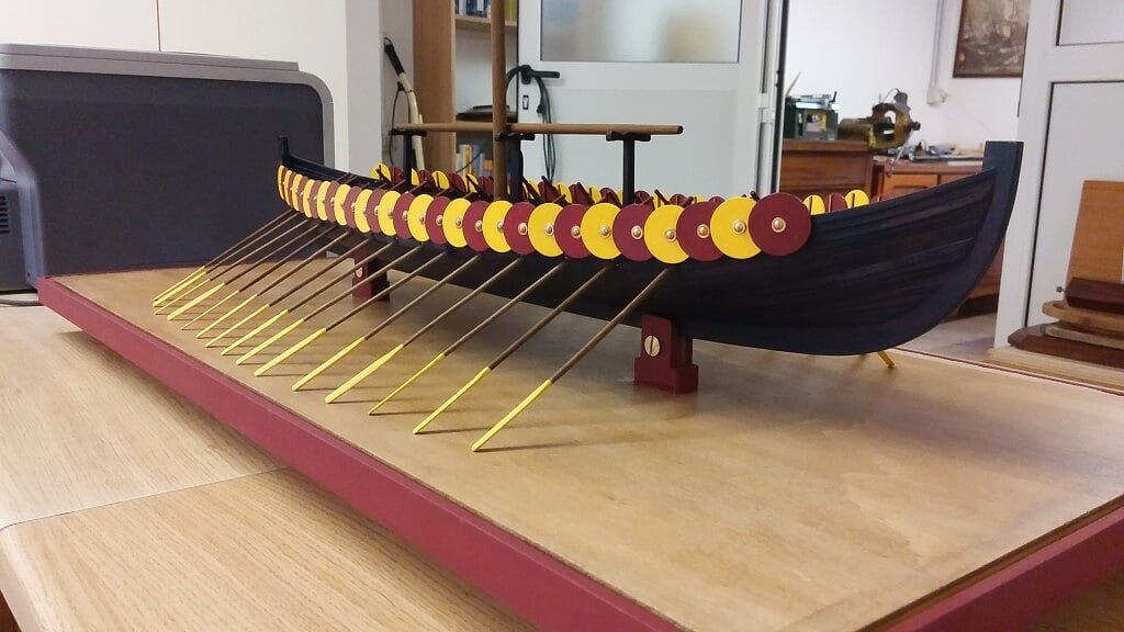
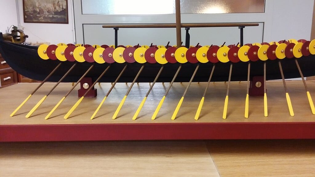
A few more photos to show the visual effect of the oars exposed outboard. This time I tried to put the model into a lower position, using another "building slip", so that the tips of the oars now lie on the hypothetical ground of the case. In this way you can better position the oars, with an aesthetic effect that seems much better to me.But with the positioning of the oars in this way the logic would dictate that the yard/sail should not be mounted. . The mast can stay installed erected but the yard should be exposed, only with the inferred sail rolled up, on special supports amidships. They are three in total but the pictures here show only the middle one, placed on the deck.
01 20160712_181741.jpg
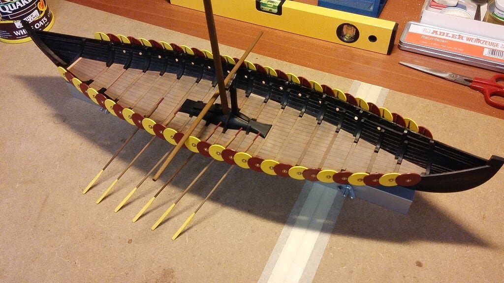
02 20160712_181731.jpg
Any Comments ? Jack.
- yvesvidal, Daniel Dusek, cristikc and 8 others
-
11
-
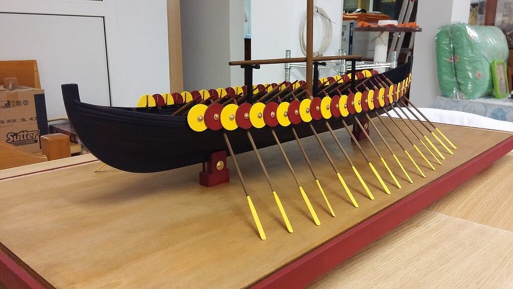
Tuesday, July 12, 2016Today I drilled the hull to prepare the oars housings: holes of 3mm diameter to be carefully drilled. In fact I started with a drill bit of 1mm, then 2mm and, finally, 3mm. Subsequently, in order to let the oar blade to pass in the hole, I run a slight lateral incision into the hole so that it lets only pass the blade and not the rest. Obviously the lat incision is made in the right direction for the force applied during the rowing. The finishing is made with a round nail file to remove burrs and a coat of stain to darken the wood thickness that, after the drilling, is clear.
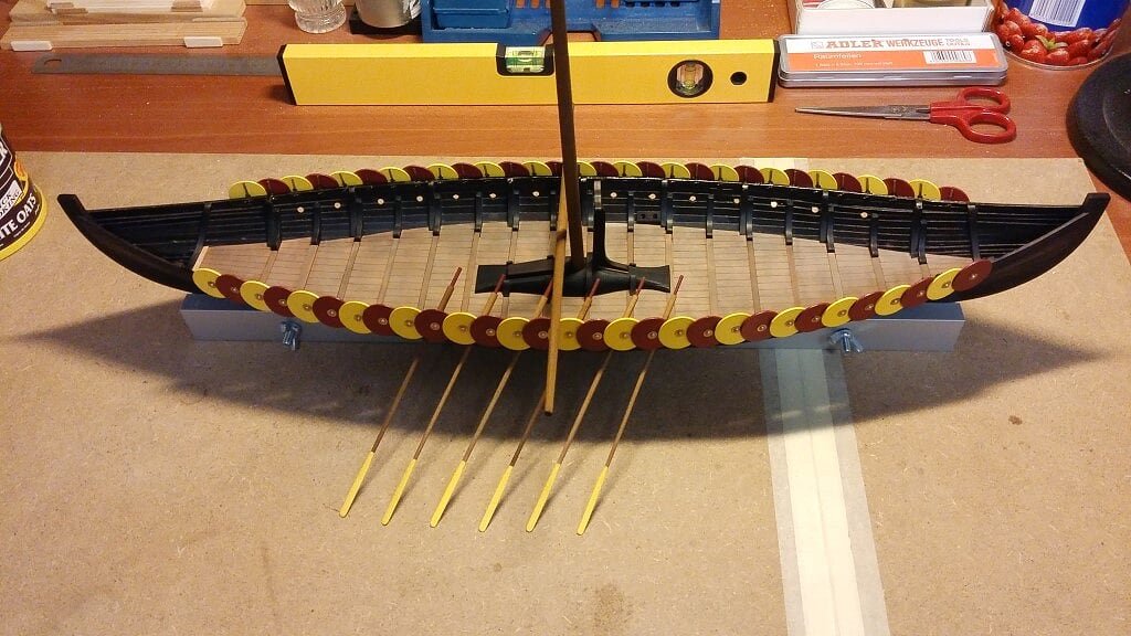
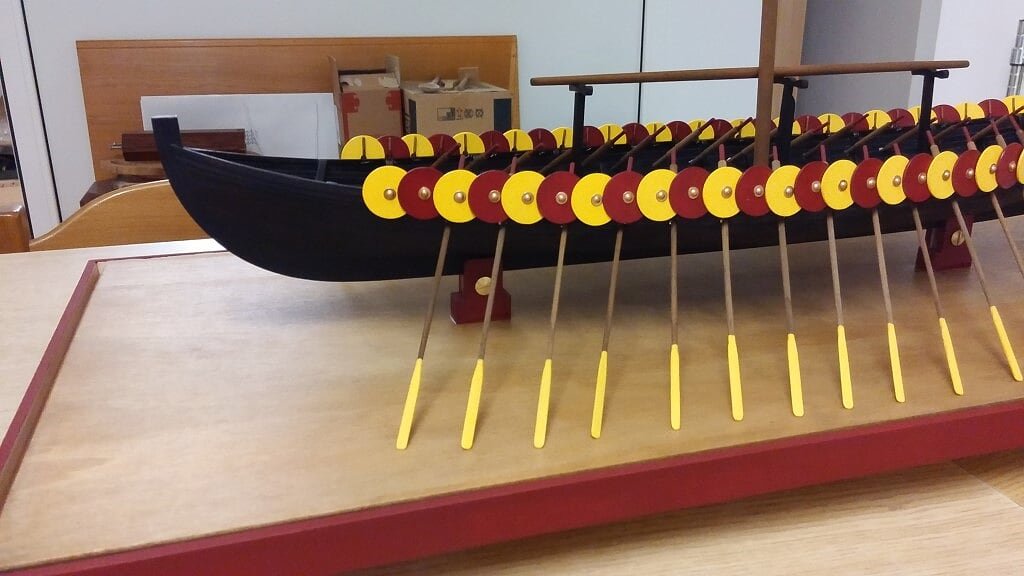
Display test for the finished model, with oars inserted in their slots. . what about ?
There is a drawback: the greater width of the display case, but on a model of this size this is not a real problem. I'm also thinking that probably it's not the case of aging alchemies for the oars, because the coordinated view with the shields does not seem out of place at all. .
Regards, Jack.
01 20160712_125238.jpg
02 20160712_125231.jpg
03 20160712_125223.jpg
-
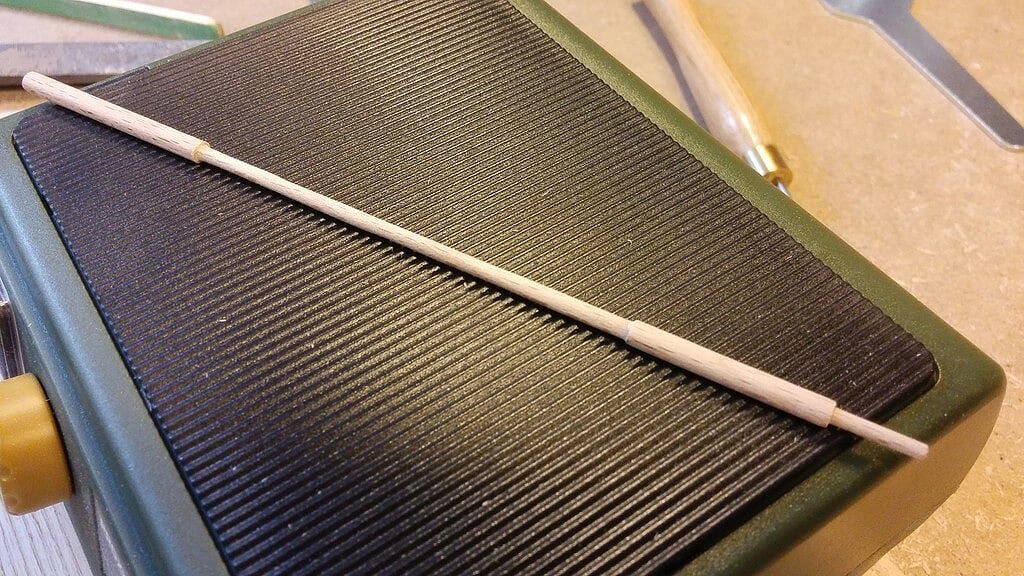
Saturday, July 2nd, 2016Second phase of the oars construction: the blades have already been shaped by a specific processing, using, for roughing, the belt sander BS/E from Proxxon fixed on a vise in a inverted position and, for finishing, a normal sandpaper. Then, when the 30+ blades were over, I went further to stain the wood as its natural color, as you can see in the picture 02, is too light.
01 20160629_172404.jpg
02 20160629_172351.jpg
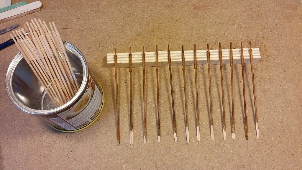
Finally, I painted a) the blades (work still in progress, four coats of paint are needed !!) with the same acrylic yellow used to paint the shields and
 the handle of the oar, painted with the same dark red used for shields too.
03 20160703_171942.jpg
04 20160703_171746.jpg
Their appearance seem now to much new !! Just left the shipyard . . Thinking to another ageing process.
To next time, Jack.
-
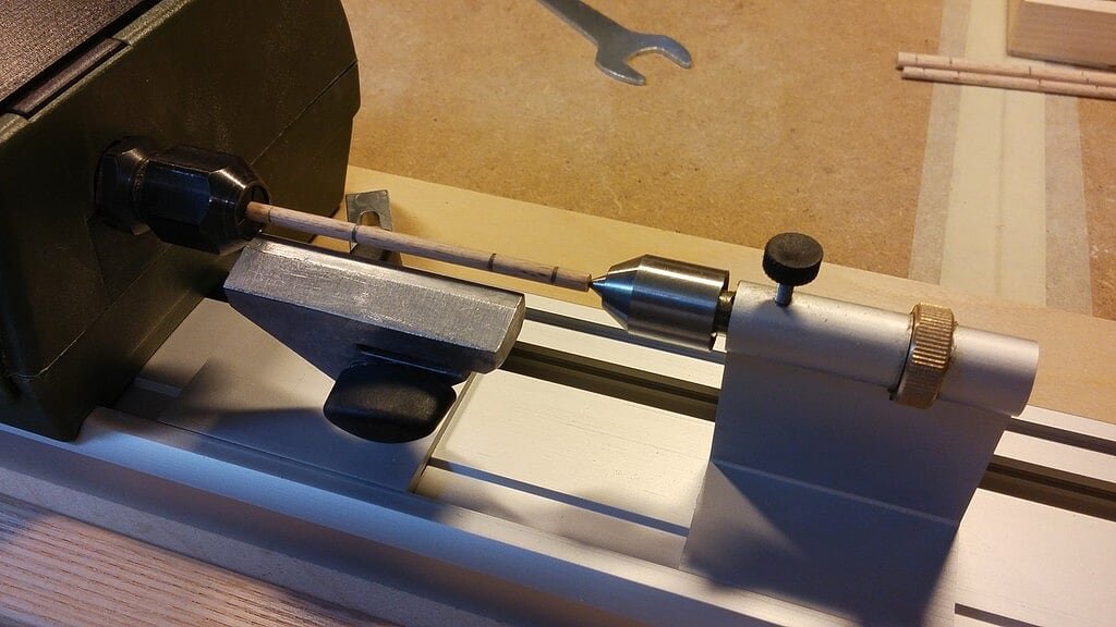
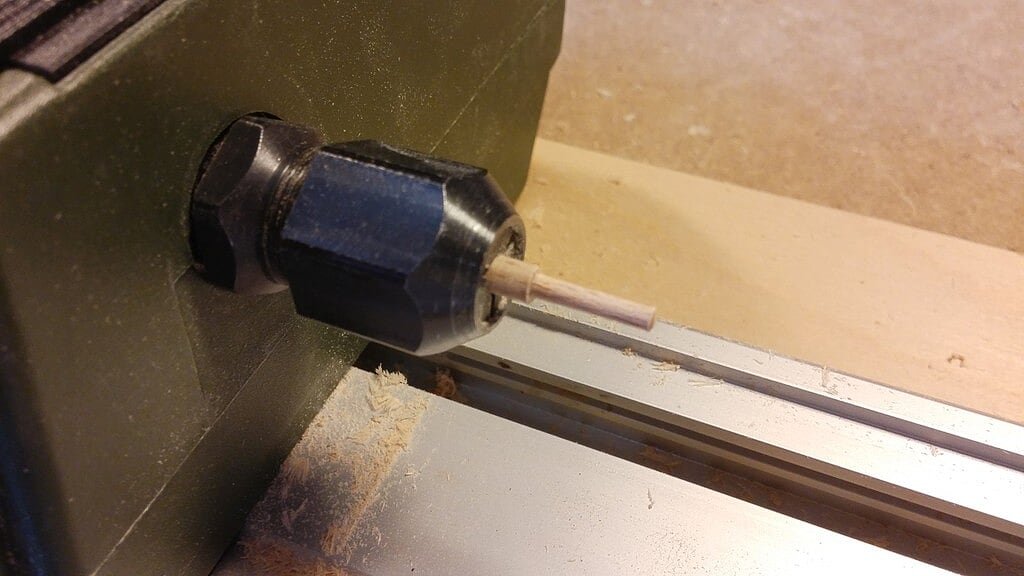
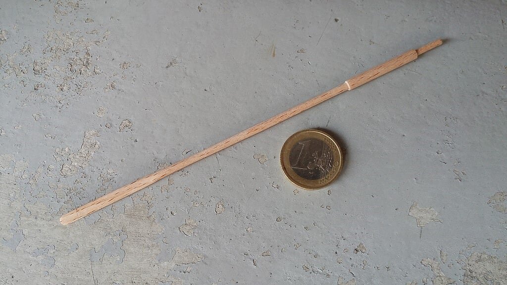
How I made the ship oars with my wood mini latheSome days ago I was asked to prepare a tutorial about the method I used to prepare the 30+ oars of the Gokstad Viking ship. During the session I build the last five oars still needed I took, after each important step, an image of the work done. This in order to make (I hope) easy to understand how I worked and the correct usage of the lathe for this task.
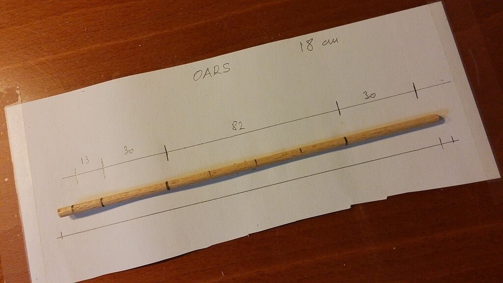
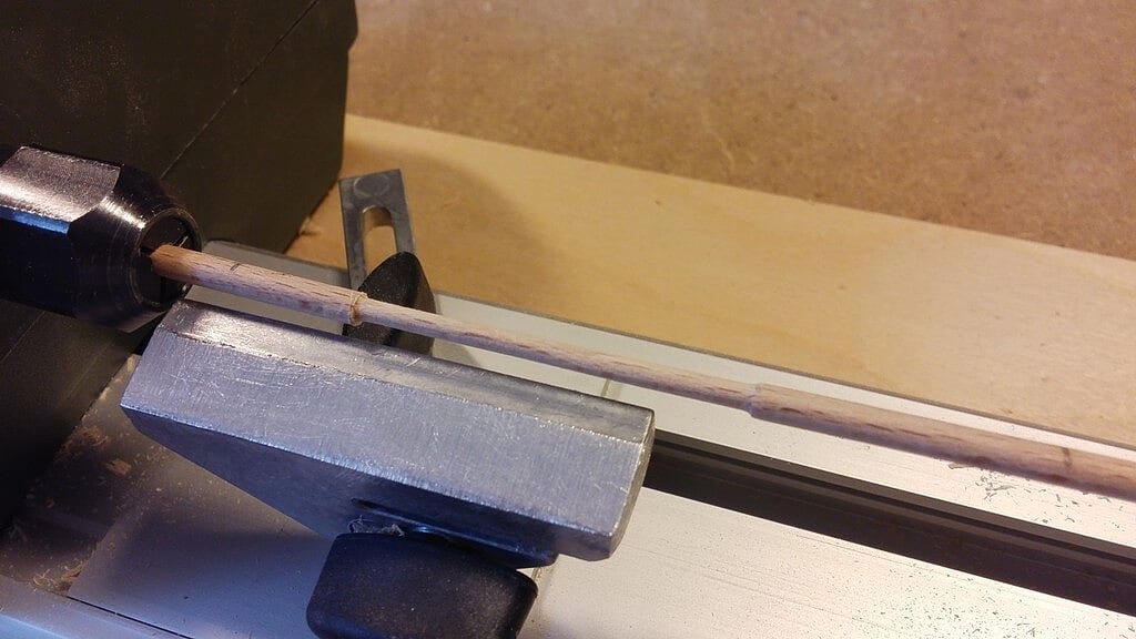
Image 01 shows the raw material I used to build the oar: a rod of beechwood with diameter +/- 4mm. The total length of each rod is in my case 18mm circa and each oar has four segments of 13mm (handle, +/- 1.5-1.7mm diameter), 30mm (not to work on), 82mm (to be reduced at 2.5mm diameter), and the remaining (blade, not to work on for the moment). Each segment is marked on the rod with a pencil before starting to work on the lathe.
01 Tornio/10_zpslvyqlcxx.jpg
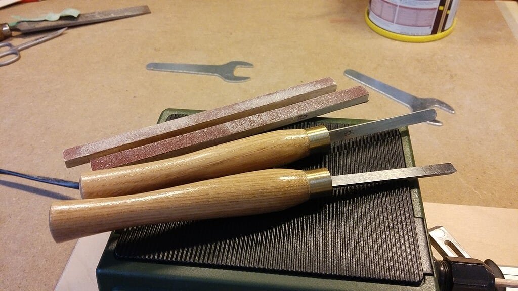
The tools used for this task: mini sanding blocks of different grade, chisels of different shapes: everyone will find the better suitable for him or for the task.
02 Tornio/15_zpswkv2wz7r.jpg
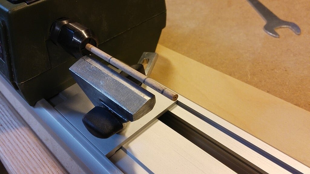
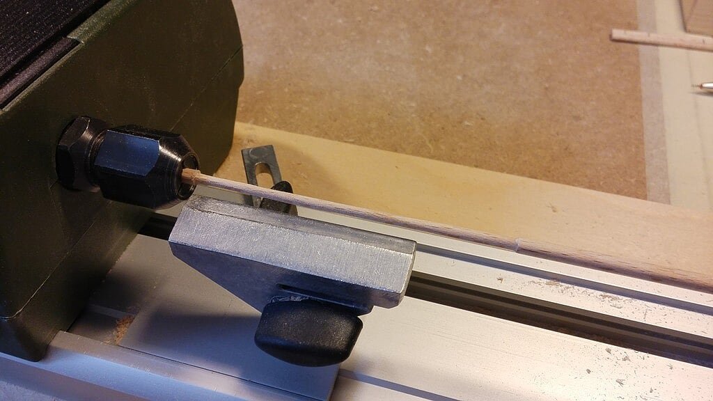
Insert the rod into the lathe clamp after having previously drilled a small hole on the tip close to the handle side. Clamp the rod 20mm after the end of the 13+30mm markers. Block the stable tool support as close as possible to the rod.
03 Tornio/20_zps0cdgbgg3.jpg
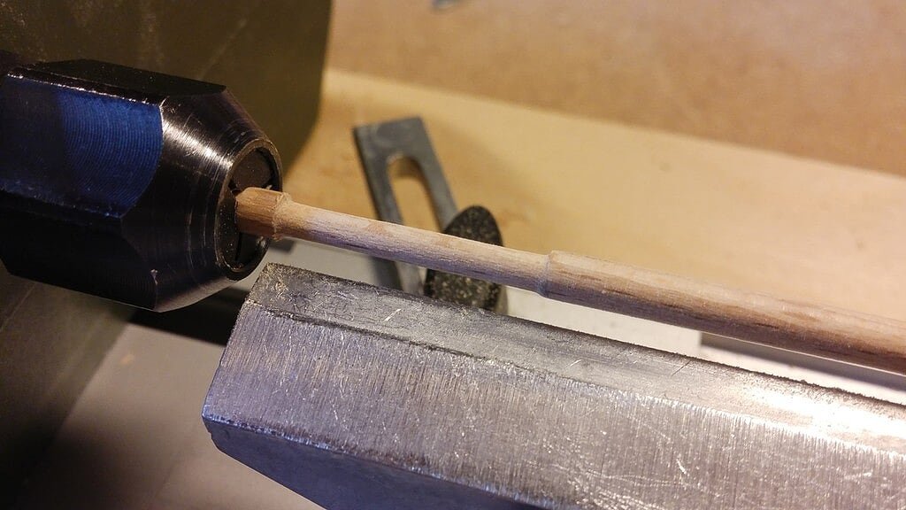
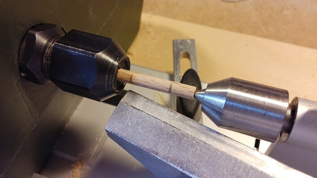
Position the tailstock with the quill travel, center the small hole on the tip and block it.
04 Tornio/25_zpsfgbeqfhn.jpg
Power on the lathe and reduce the diameter of the rod as shown below with your preferred tool. Personally I use first the chisel and later the sanding blocks to refine.
05 Tornio/30_zpsw25jxosg.jpg
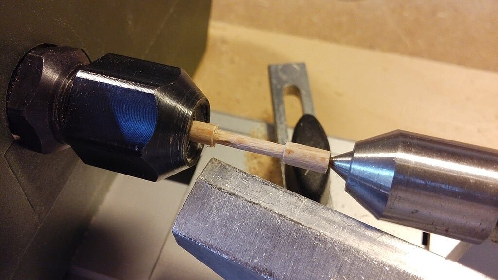
Poweroff the lathe and extract another 2mm rod from the lathe and clamp it again . .
06 Tornio/35_zpsrwk9niuu.jpg
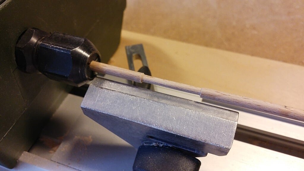
Power on the lathe and restart the diameter reduction for the next 20mm segment . .
07 Tornio/40_zpsoypuqveo.jpg
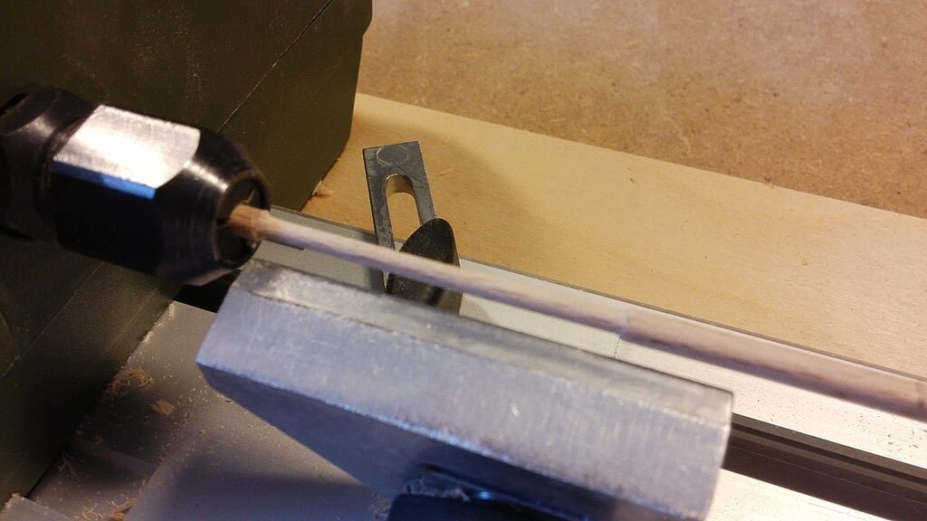
Repeat the steps until you reach the end of the 82mm. segment. The reason I proceeded working only of 20mm segments is related to the flexibility of the reduced diameter area (about 2.5mm). If you work on longer segments you risk to break the rod and the complete work done is then lost.
08 Tornio/45_zpswnjneuau.jpg
09 Tornio/50_zpsj5xn71tv.jpg
At this point insert the rod into the lathe, close to the oar handle. Clamp the rod and position the tailstock again.
10 Tornio/55_zpsmgdzlrdj.jpg
Lathe the oar handle. The handle should have a diameter of 1.5-1.7mm.
11 Tornio/60_zpsuryuj1gr.jpg
Cut the excess tip, now no more useful and refine with sanding block.
12 Tornio/65_zpsfiqoqsl2.jpg
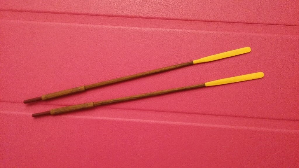
Extract the oar from the lathe; now this task is over and it remains only to shape the blade . .
13 Tornio/70_zpsgirr6tfm.jpg
All the oars are finished . . although the blade shaped tips are still to be done . . will be a matter for next messages.
14 Tornio/20160621_163501_zpsi2myuze1.jpg
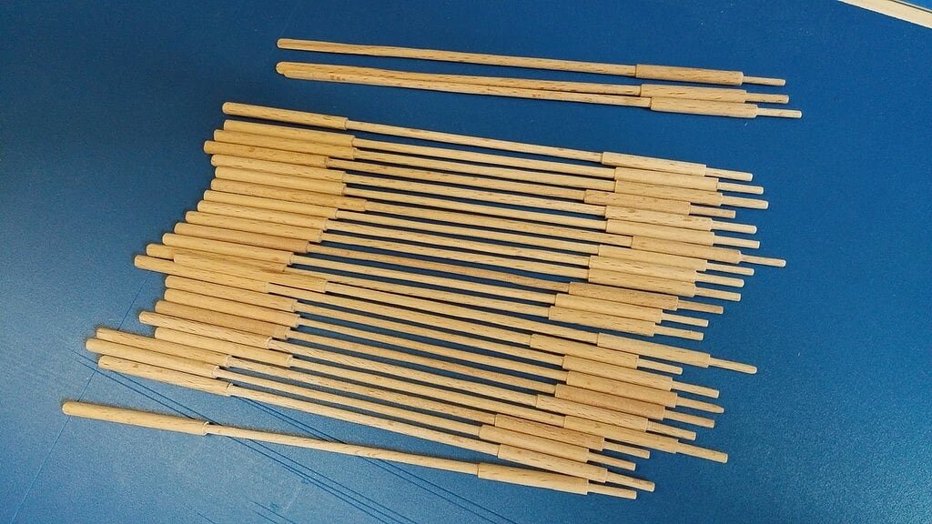
That's all for now . . to the next progress step (blade tips).
Regards, Jack.Aubrey.
-
I would greatly appreciate if you would like to describe how you made those great oars! I´m going to build the Dusek Bireme as my next model and that one has many oars. So to avoid doing the same mistakes a tutorial would be great.
Hi,
it should be a nice idea.
When I'll resume the building of the last five oars I'll try to take some photos of the entire process and then I'll try to setup something.
Unfortunately I can't take a movie (that should be probably the best) because I need someone that takes it while I'm working . . but I'm alone.
Rgds, Jack.
-
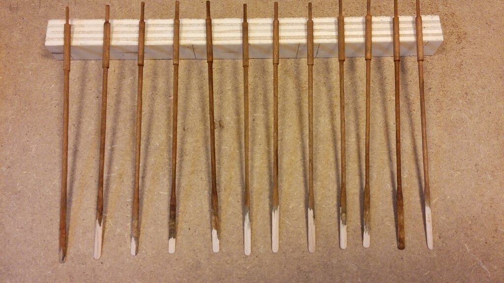
Tuesday, June 21th, 2016
About 10 days ago I posted my last message where I showed the "first oar" for this ship. The oar was made using a minilathe for wood.
Here what happened during these past 10 days:
- the first two days I was able to build only three new oars as my limited experience with the lathe led me to break many pieces while using the tool in an unsatisfactory way;
- then, slowly and mistake after mistake, I learned the right method and the correct sequence of execution and from that moment I had no more broken pieces;
- however, given the repetitive and boring nature of the task and its relative slowness, I set myself the goal to run 5 oars per session, not more.
Now it remains to prepare the last five oars and this task will be finally over . .
01 20160621_163446.jpg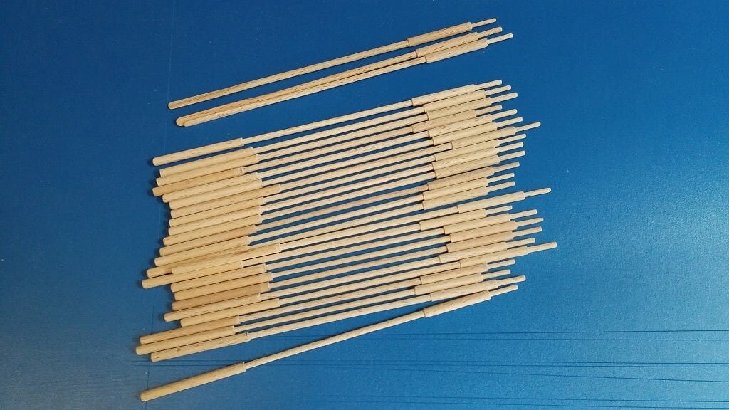
In the above picture you will notice that, apart from the three oars at the top, the tip (blade?) is not yet shaped. This will be the next step as soon as the last five will be ready.
The temptation to paint the tips with the same yellow color used for the shields is strong. Perhaps, for the rest of the oar, the obvious color should be the same tar brown of the hull but I would prefer a lighter nuance, to add more color effects at the whole model.
Cheers, Jack. -
Druxey,
I can submit a first, fast answer about your question.
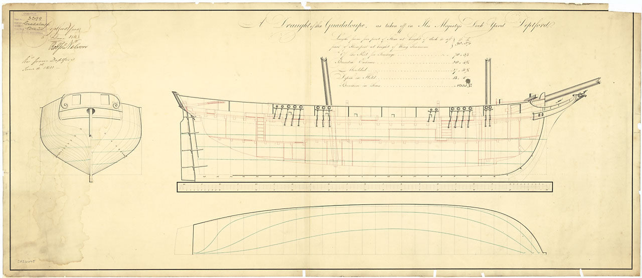
Le Nisus was captured by the RN becoming HMS Guadelupe on December 12, 1809. HMS Gaudaloupe sailed to Deptford (UK) where she underwent fitting-out from August 23, 1810 to January 23, 1811.
Now give a look to the comments after the full plan image here below: the date of the plan is June 6th, 1811. This date is after the fitting-out in the british shipyard, so this "should" mean that the plan represents the ship after its modification . . . but the sentence "prior to fitting as a 16-gun brig sloop" probably means the opposite.
Do you agree ?
But the question for me still remains 'cause the "prior to fitting as a 16-gun brig sloop" sentence is not contemporary of the plan but added in recent times by a NMM curator . . and probably may not be considered 100% true.
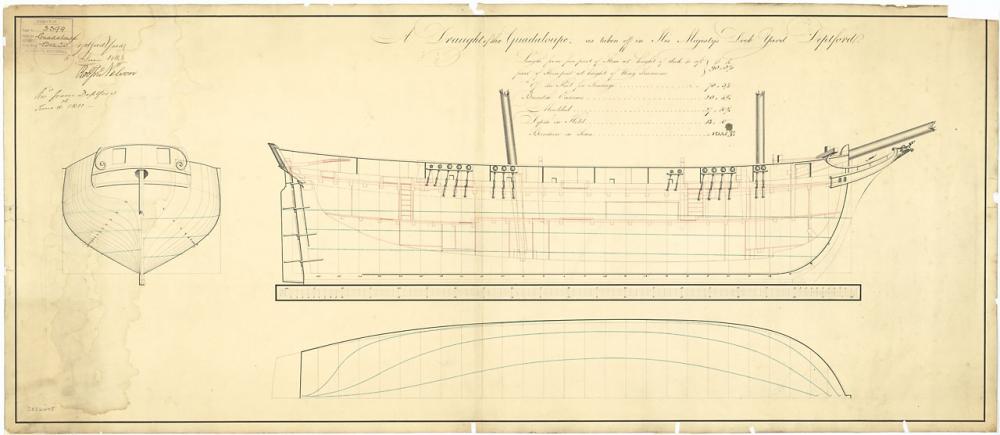
Description
Scale: 1:48. Plan showing the body plan with stern board outline, sheer lines with inboard and figurehead, and longitudinal half-breadth for Guadeloupe (captured 1809), a captured French brig, as taken off at Deptford Dockyard prior to fitting as a 16-gun brig sloop. Signed by Robert John Nelson [Master Shipwright, Deptford Dockyard, 1806-1813].
Date made
6 June 1811
Place madeEngland: London Deptford Dockyard
Credit
National Maritime Museum, Greenwich, London
Materials
black ink; green ink; red ink; paper
Measurements Sheet: 479 mm x 1103 mm
- aviaamator and mtaylor
-
2
-
Hi Druxey.Are the English plans after modification or 'as captured'?
To answer you I need to identify on the NMM plans their dates and then compare with the date of capture and of commission. Be a little patient, I need to stay on my workshop but I can't for a couple of days due to other commitments. Regards, Jack.
-
Sunday, June 12, 2016
I finally took a few pictures of the HMS Guadelupe plans I purchased at the Greenwich NMM.
The five images below proposed highlight the five areas that I have (so far) identified as main differences between this plan and the one provided by the ANCRE monograph of "Le Cygne".
But . . I forgot to take the same images of the ANCRE plans, so we'll have to wait I get pictures of them too. Now we can only visually introduce the five differences shown here below.
So please . . have some patience for a while.
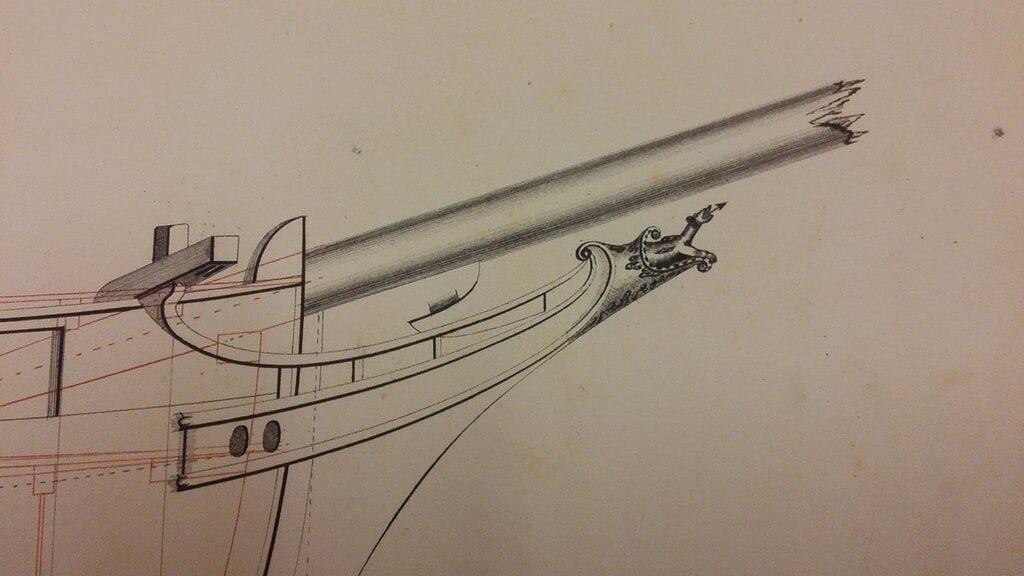
1st difference at prow where no one knew until now how it was done: the figurehead. In addition, the bow shape is different, slimmer and slender.
01 Brick%20de%2024%20Plans/20160611_114237_zpsigmpluxt.jpg
2nd Difference: the side quarter badges are totally missed.
02 Brick%20de%2024%20Plans/20160611_114302_zpskjwrajos.jpg
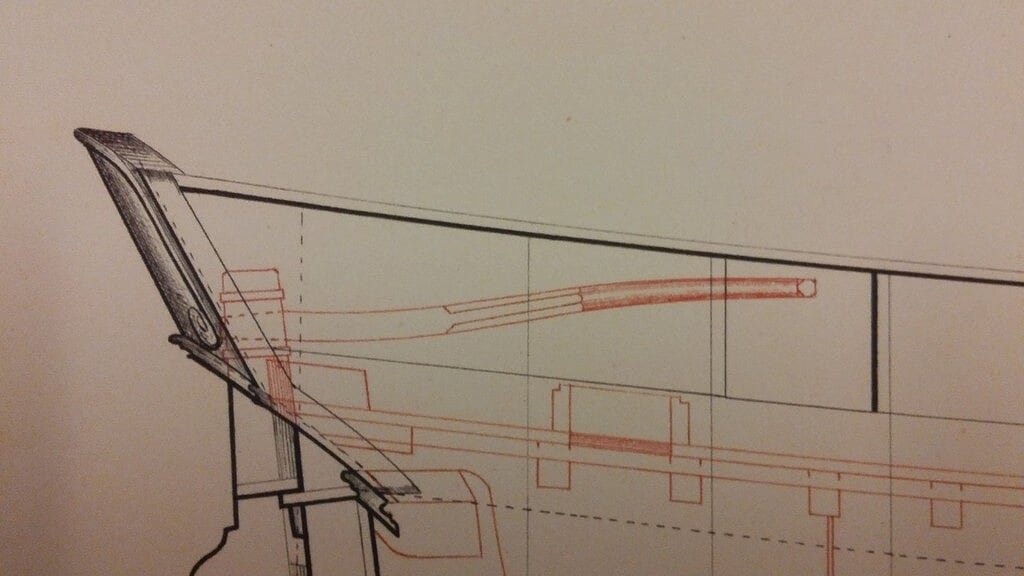
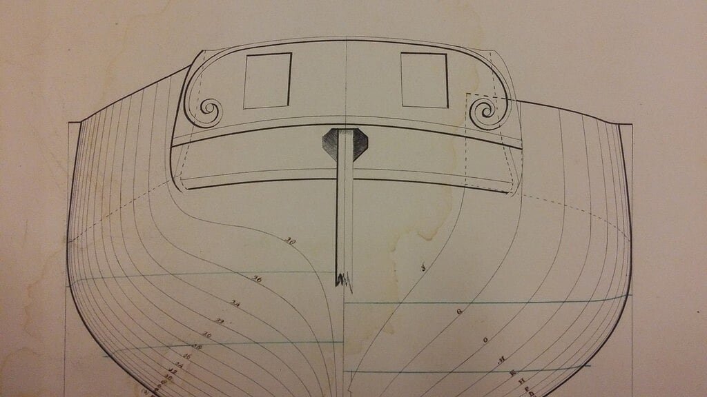
3rd difference: the profile of the transom/taffarel is different from "Le Cygne", narrower and with square gunports.
03 Brick%20de%2024%20Plans/20160611_114415_zpsqajhnadd.jpg
4th and 5th difference: the shrouds positioning of foremast and mainmast are different than "Le Cygne"".04 Brick%20de%2024%20Plans/20160611_114246_zpspkhdqmrq.jpg
05 Brick%20de%2024%20Plans/20160611_114252_zpsg8j2xzwa.jpg
But there are also other minor but still important differences.
As soon as I can spot pictures of the ANCRE plans you will probably understand better.
That all till now.
Regards, Jack. -
Sunday, June 12, 2016
After a few days of training on the usage of the mini lathe PROXXON DB250, when finally I felt ready enough, I started to build a couple of oars which equipped the Viking ship.
The starting raw material is a 3mm beech dowel. The kit provides rods of the same diameter of lime wood. I preferred to use the beechwood because during the tests the limewood sometimes broke. This problem never occurred me with a harder wood such as beech.
To lathe the handle of the oar (diameter 1.5 mm) and the main part of the oar (diameter 2mm) it takes a lot of patience and care.
Once finished with the lathe, to shape the blade I used the belt sander PROXXON BS/E, much more effective than other manual tools such as files and/or sanding blocks.
Anyway, to build an oar with this procedure I took about 30 minutes, most of them working at the lathe . . . so far so good but the problem is that I have to build 30 of them !!!!
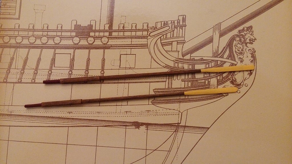
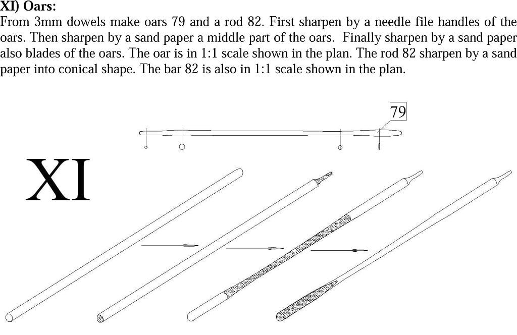
Here below a picture of what the instructions say and two photos of how I interpreted, in my own way, the shape of the oar. Once completed the oar will then be dyed with mordant, even if the idea to paint with dark red or yellow the oar blades is strong . .
Cheers, Jack.
01 Oars.jpg
02 20160611_193228.jpg
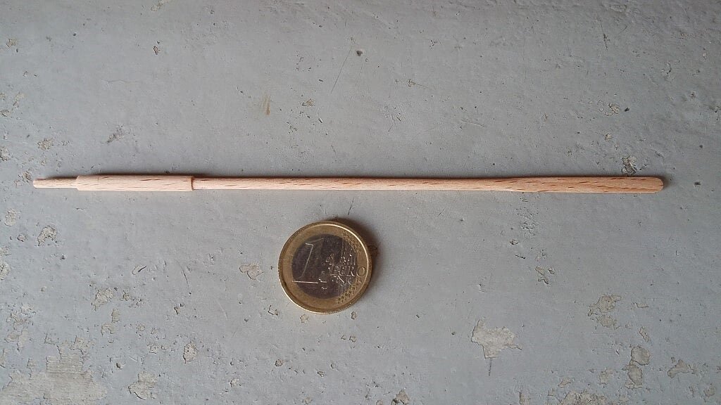
03 20160611_193155.jpg
-
-
Wednesday, June 8, 2016
It is now +/- three weeks since I went back from Tuscany and it's just few days I began to think back to shipmodeling. Two days ago I reopened the Gokstad Viking shipyard, which, if everything runs well without glitchs, could be completed in a relatively reasonable time, that is, before I'll return to Tuscany in September.
On the other side, regarding the HMS Guadeloupe, everything is still in wait state. First I need to collect my thoughts because more than six months of inactivity made me forget many things. In Tuscany, I concentrated more on the history of this ship and, having discovered the existence of an original contemporary plan available at the National Maritime Museum in Greenwich, I intrigued to buy it.
Definitely a good purchase, which clarifies many aspects regarding the appearance of this ship, which also differs in rather important points from the French project: figurehead, breakwater, main piece of the knee of the head, quarter badges, shape of the taffarel, positioning of the shrouds. It's my intention to take pictures of these details, to illustrate in deep the differences, in future posts.
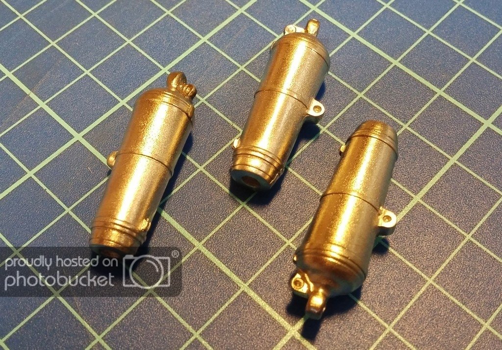
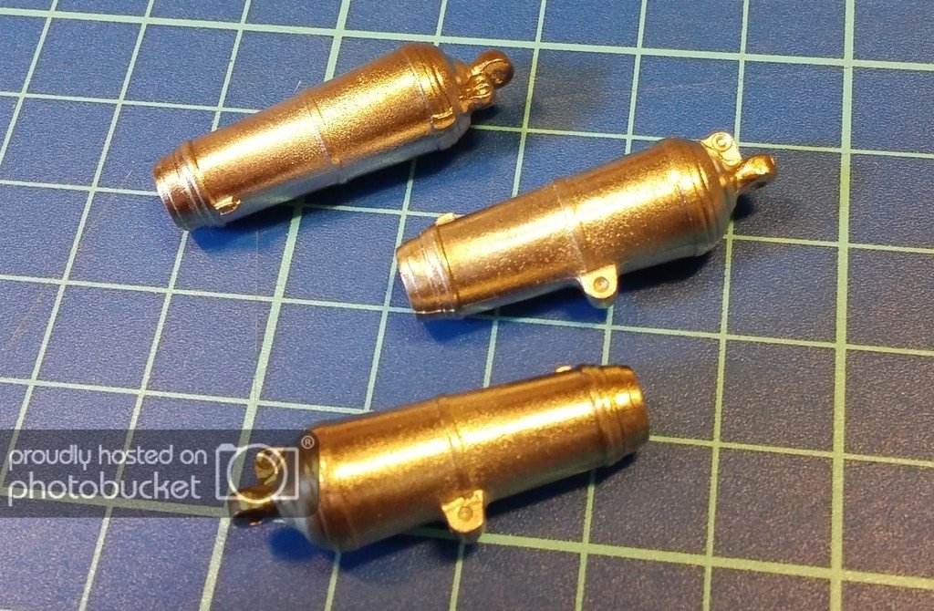
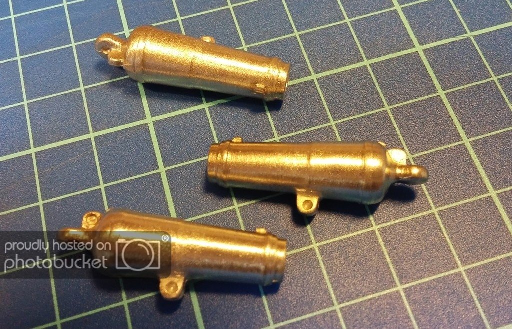
Meanwhile, thanks to the collaboration with another modeler who is building this same model (he decided to name it "Le Colibrì") it was started the realization of the ship carronades. A master of these parts was made. More in deep two of them: a) one for my friend who uses the original "Le Colibri" carronades, reproduced in detail in the ANCRE plans,
while for my model, which was armed after his capture by the Royal Navy, the master was made using a English-barrel pattern, almost similar but not equal to the french one. Thanks to researches on the internet I found the design that I needed.Finally, my friend found and contacted a company in Gazzada Schianno (VA) which set up the fusion process of the pieces needed starting from the masters. All this is the result of my friend work, I limited myself, due to my absence, to simply pick up the pieces and to pay the due amount, amount which will then be divided between us.
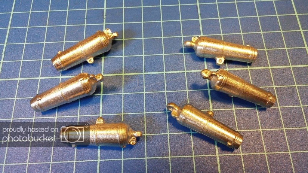
Below are some pictures of the guns barrels, both for my Guadeloupe than for Le Colibrì.
HMS Guadeloupe:
01
02
Le Colibrì:
03
04
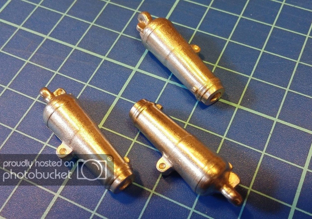
Both barrels in the same image, left the English ones . .
05
Cheers, Jack.
PS: The color of the metal, which in the pics seems almost golden, is strongly distorted by artificial light, in reality it's very similar to silver (the material used for casting is a pewter alloy, I don't remember the right name). Obviously, the pieces have to be treated to give them the classic "gun metal" color . .
-
Tuesday, June 7th, 2016
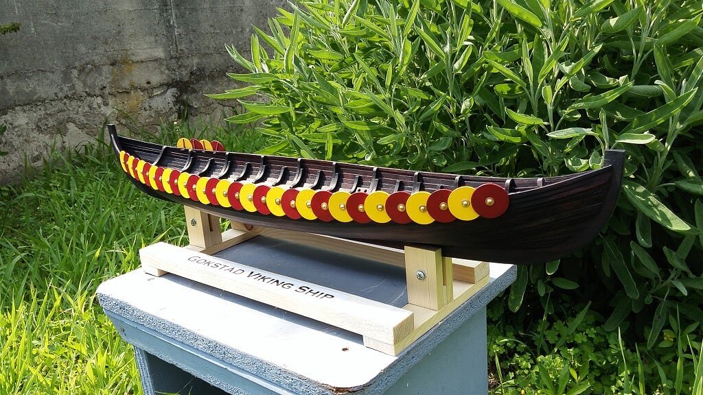
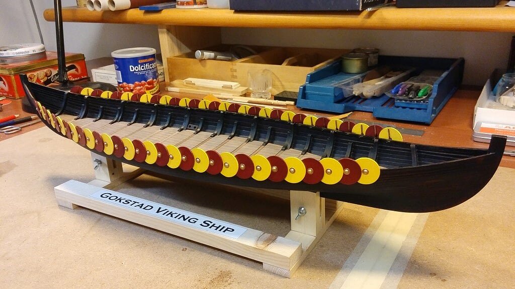
The starboard side of the ship is now over, with all its shields in place . . now it's time for the port side.
Is more beautiful the Viking ship or the sage plant in the background ?
01 20160607_160807.jpg
02 20160607_160823.jpg
03 20160607_160836.jpg
-
Monday, June 6th, 2016
QuoteIt's now coming the time to come back to my house near to Milan, after +/- six months passed in Tuscany. For this reason I'm going to close the shipyard here but, considering that the main amount of work on this model is over, I'm thinking to pack everything and to continue at home: considering what remains to do, it's reasonable to imagine the completion in a couple of months, also sharing the time with the other shipyard (HMS Guadeloupe) I'm managing there.
Most probably, my next messages will be originated from my main workshop in Milan where I think to stay until the end of August. If I'll be successful in finishing the Gokstad ship in time, my next return to Tuscany will probably coincide with the start of a brand new model.
Kind regards, Jack.Aubrey
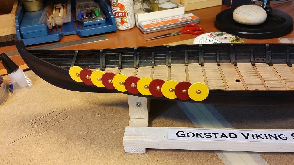
According with my previous statement, here quoted, I've resumed today this shipyard.
I came back to my house close to Milan two weeks ago but I had too many task to take care before modelling, so I can start something on the Viking ship only today.
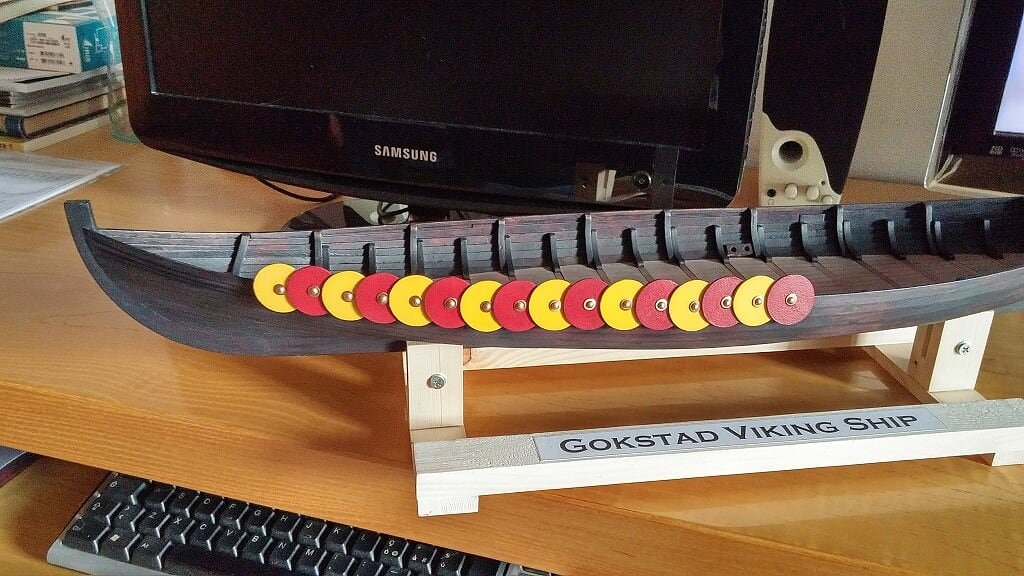
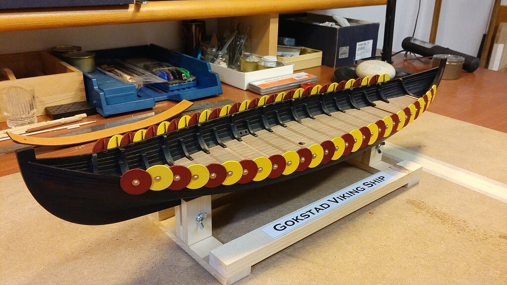
I'm installing the several shields on the sides of the ship. These shields were a typical feature of these ships. Here below two images of the work done today, just a quarter of the whole.
Regards, Jack.Aubrey.
01 20160606_160424.jpg
02 20160606_201312_HDR.jpg
-
Many thanks to all of you for your positive comments.
I believe it's the strenght of this kind of software applications, such as forums, to simplify and favour the exchange of experiences and ideas between their members. In our case modellers. Another positive effect is to encourage potential new modellers to start, being sure that they can easily find support when needed.Without the motivation coming from your suggestions I'd probably followed another method . . may be better or not, who knows.
It's now coming the time to come back to my house near to Milan, after +/- six months passed in Tuscany. For this reason I'm going to close the shipyard here but, considering that the main amount of work on this model is over, I'm thinking to pack everything and to continue at home: considering what remains to do, it's reasonable to imagine the completion in a couple of months, also sharing the time with the other shipyard (HMS Guadeloupe) I'm managing there.
Most probably, my next messages will be originated from my main workshop in Milan where I think to stay until the end of August. If I'll be successful in finishing the Gokstad ship in time, my next return to Tuscany will probably coincide with the start of a brand new model.
Kind regards, Jack.Aubrey -
Here some new images . .On the terrace, cloudy weather, no flash . .
01 20160427_142044.jpg
02 20160427_142036.jpg
03 20160427_142050.jpg
Inside home, with flash and artificial light . .
04 20160427_145749.jpg
-
-
Tuesday, April 26, 2016After a wait state of more than a week since I prepared the vinegar/steel wool solution and having not seen any significant change in color, rather discouraged, I come to the conclusion that, before archiving this experience, it would be worth to make a couple of tests . . just to understand better this strange situation.
So I took the two solutions I prepared, one with classic vinegar and the other with apple vinegar and, as instructed, I filtered them with a sieve for tea and let them decant for +/- one hour while I went to get the same timber used for the Viking ship deck.
The amazing thing is that after about an hour since I filtered the solution and thrown away the steel wool, the colour of the two solutions "suddenly" became much more dark . .
So I proceeded to brush the two solutions on the wood samples and, after a few minutes, just long enought to let the wood dry, I realized that the solution was properly working . . and very, very well !
Encouraged, I continued with the tests. Between the two different acid solutions there were not much differences, the one with apple vinegar gave a slightly lighter color after drying. However, both seemed too dark, although realistic, for my mind.
I then diluited a part of the solution (the one with the classic vinega) with water in proportion 1 to 1 and made another test: slightly lighter result but still too dark . .
Another dilution with water and another test. I repeated this process for 6-7 times always adding water.
At the end I found the concentration that was working for me: say about 1 part of the original solution, and 9-10 parts of water. With these proportions I got a color that I felt was fine for the type of timber used. So, at this point, I decided to do the "real" work on the ship deck. The result can be seen in the two images below. The images, especially the colours, do not give totally the idea of the result: with natural light the weathering is more evidently highlighted.
Among other things, I noticed that the samples used in the tests over time tend to darken further, so what you see may change slightly tomorrow, presenting itself a few darker pattern. We'll see. I still have an additional option, if necessary: a second coat of the liquid, which will darken even more the wood, highlighting the gray tone. But I prefer to wait until tomorrow to decide . . just to see the stabilized result.
Finally, after this satisfactory result (at least for me), I want to thank all the people who participated at this discussion.
Greetings, Jack.
01 20160426_123151.jpg
02 20160426_123203.jpg


Gokstad Viking Ship by jack.aubrey - FINISHED - Dusek Ship Kits - 1:35 Scale
in - Kit subjects built Up to and including 1500 AD
Posted · Edited by jack.aubrey
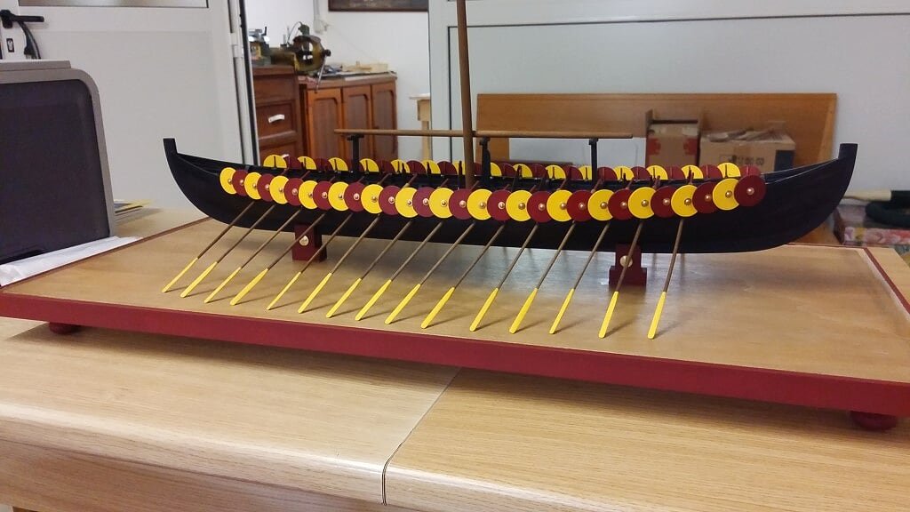
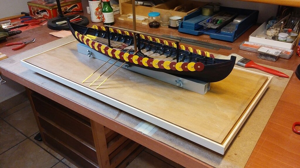
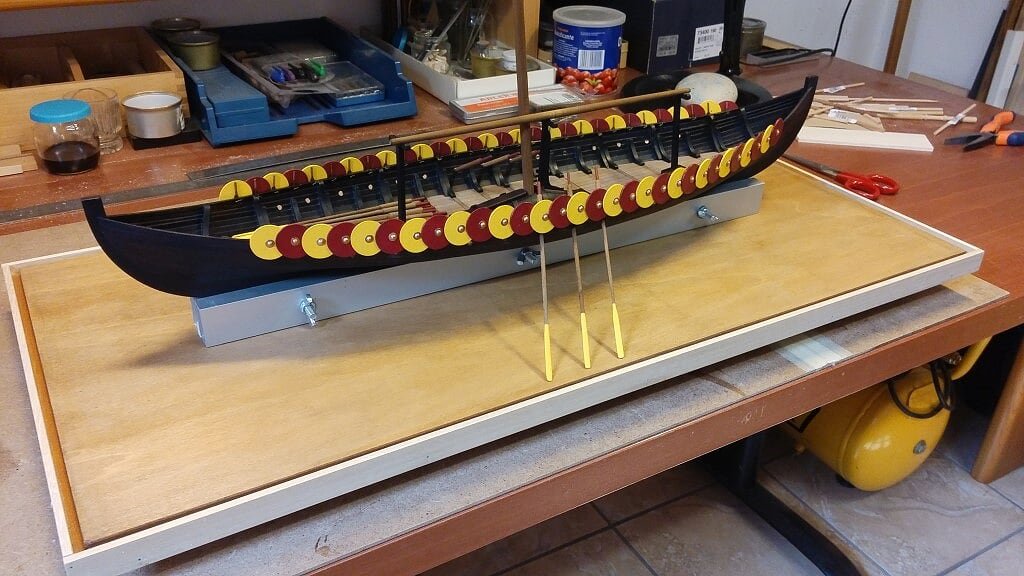
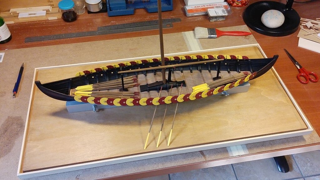
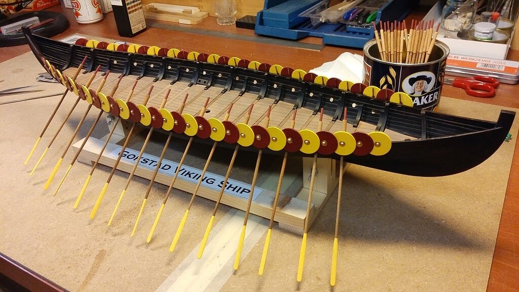
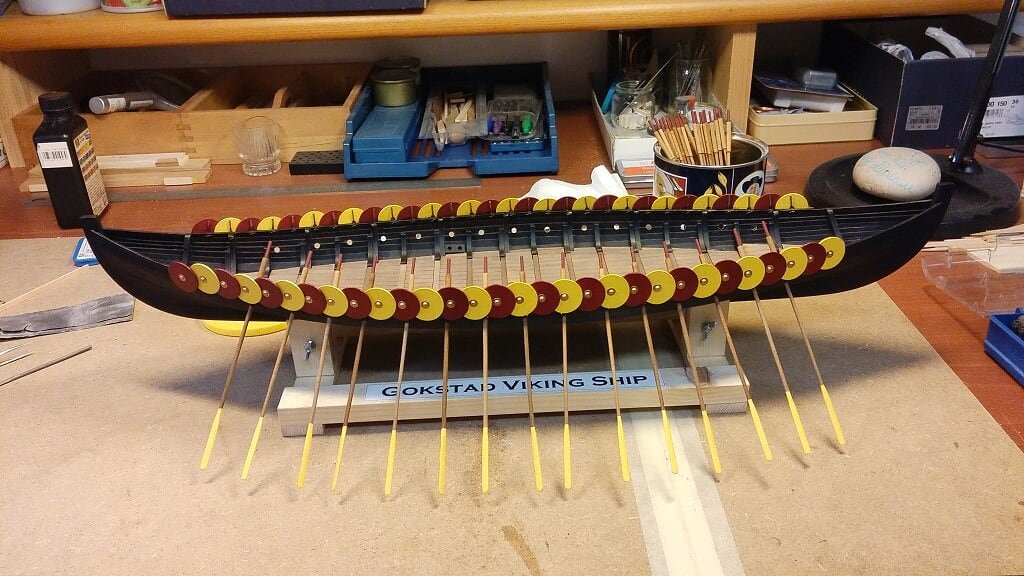
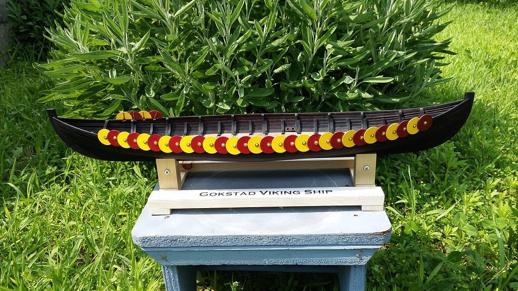
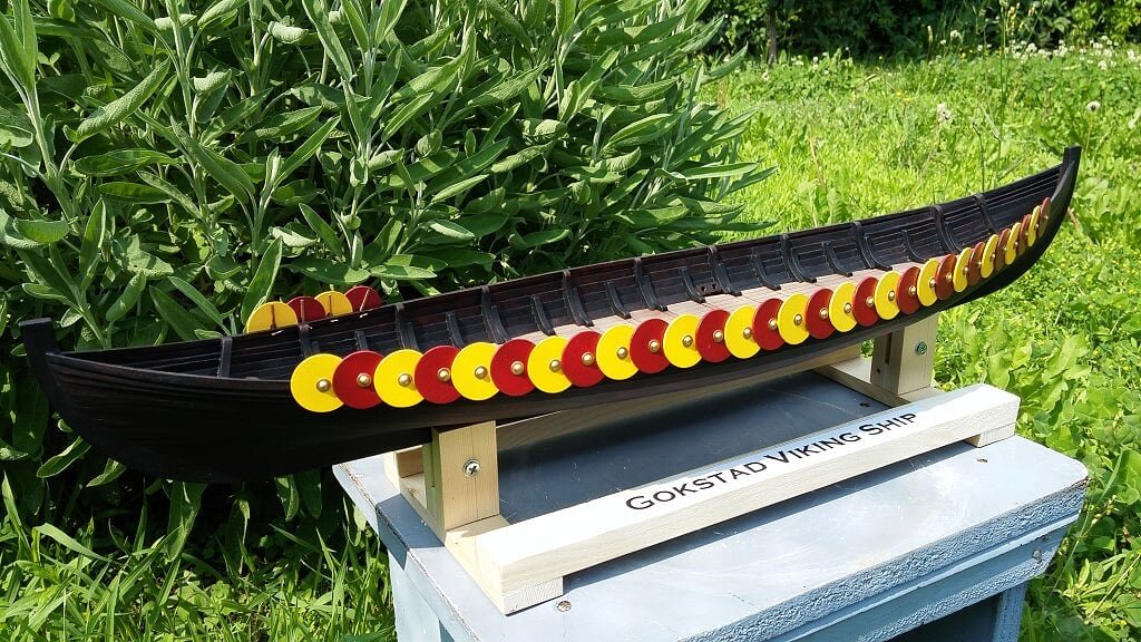
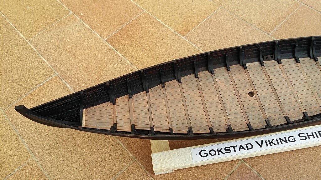
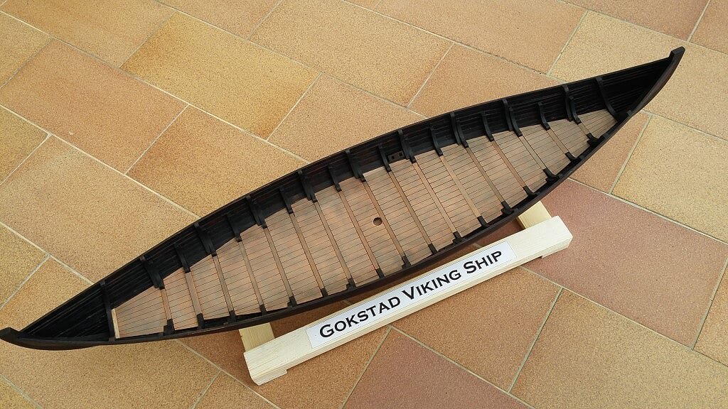
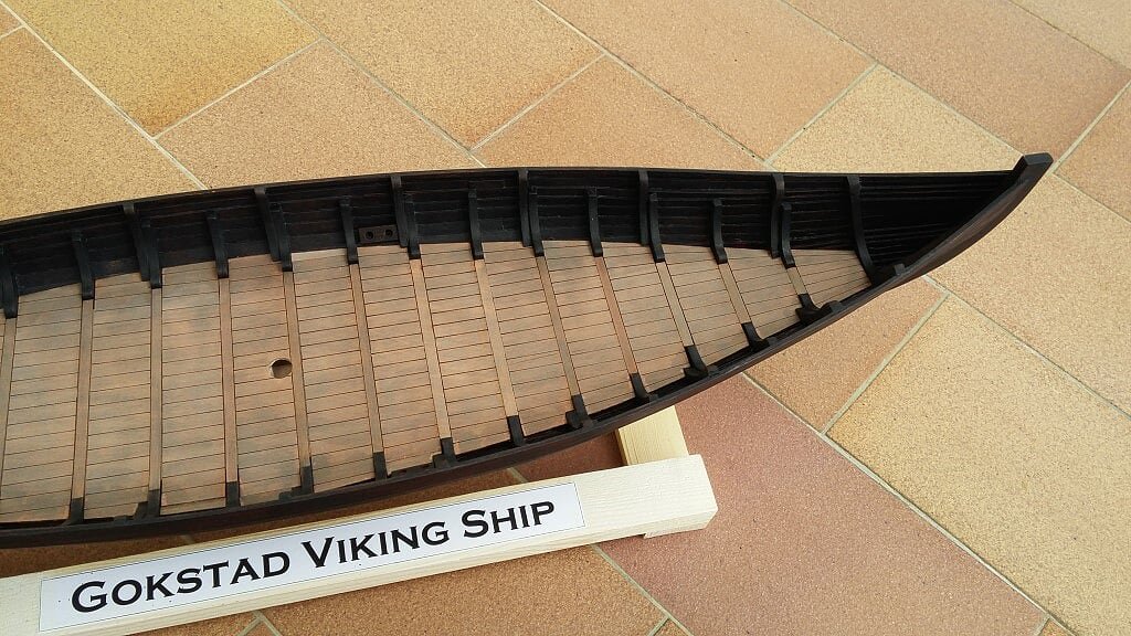
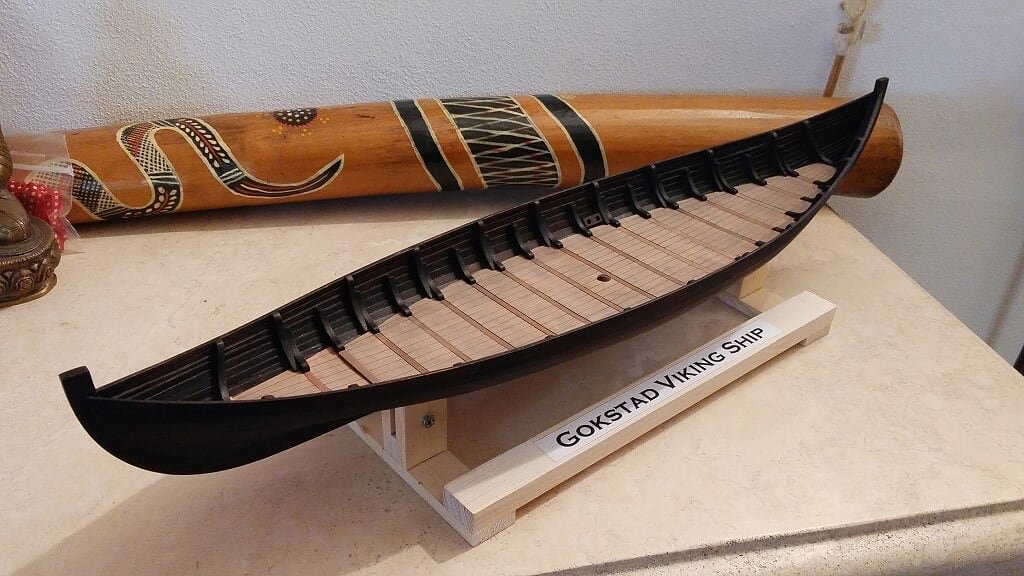
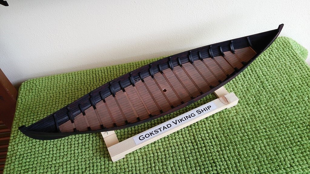
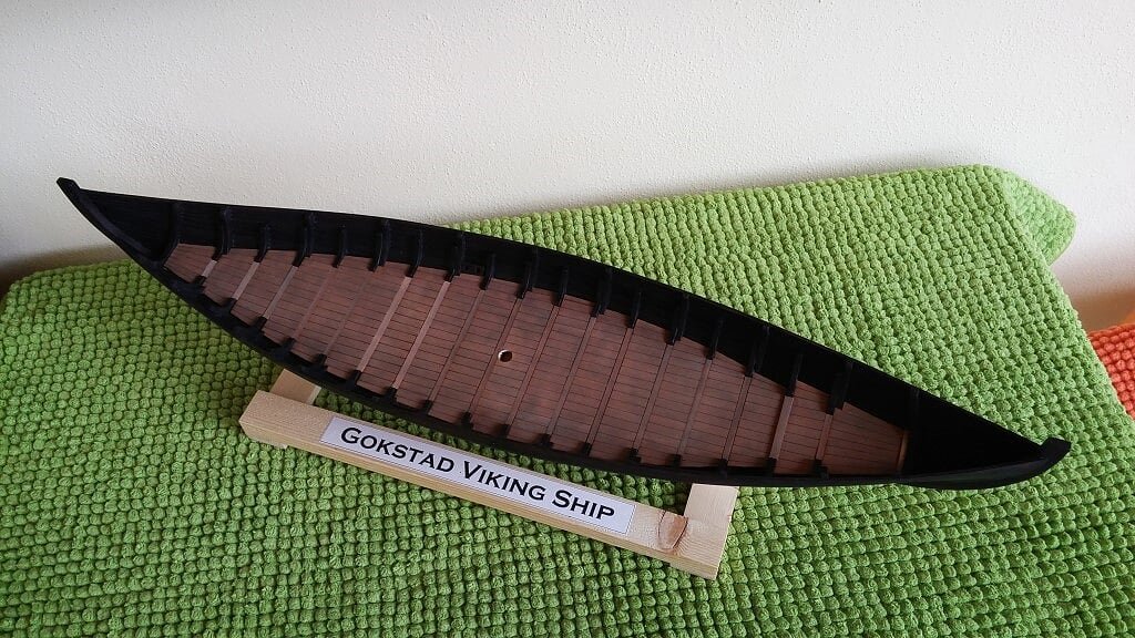
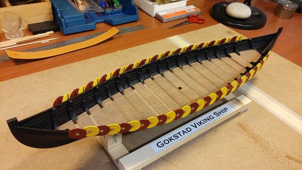
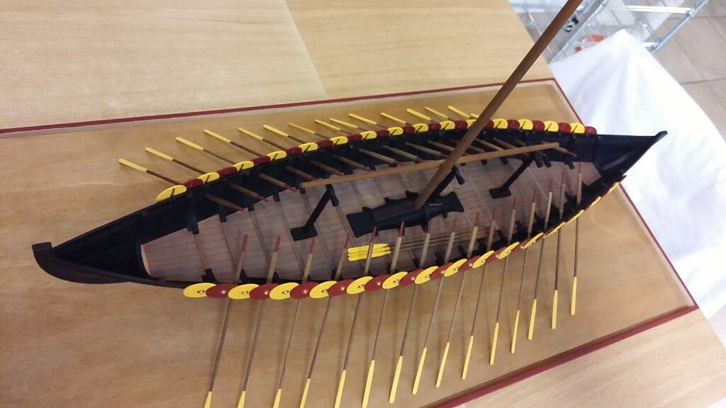
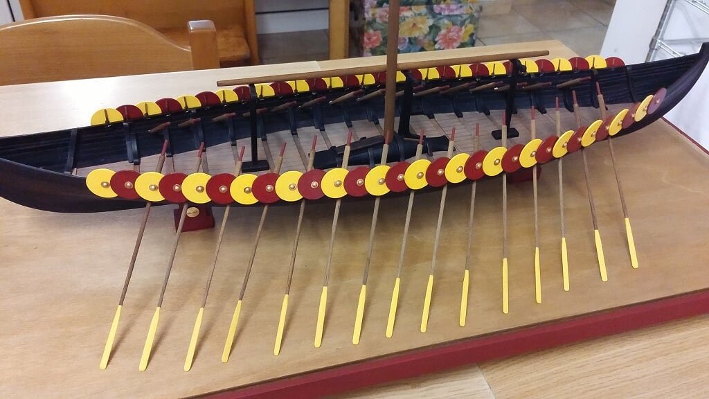
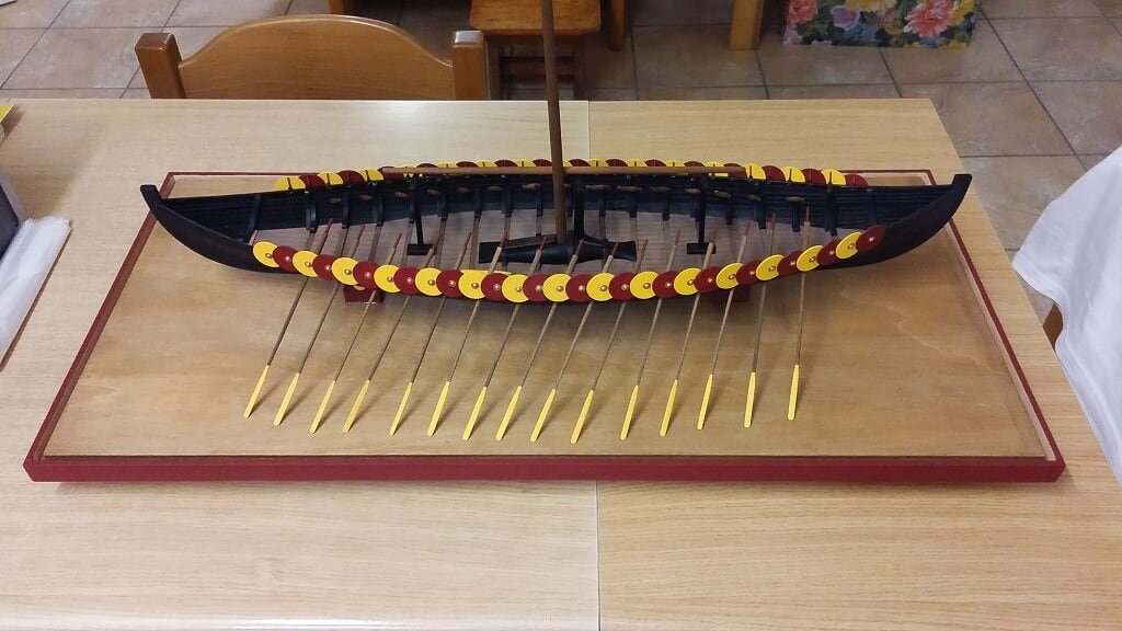
A batch of images of the model installed in its case, with all the oars shown. The base of the case is almost completed, except for one thing which will be discussed later. Till now I'll focus on definitely fixing the pieces located on the deck and to finish the seats for the oarsmen.
With respect of the element mentioned above, I have found that if I don't find an elegant way to keep held the oars, they tend to move easily from their original place. So I'm thinking at a kind of guidance with joints where inserting the blades of the oars. Obviously it must be a minimal and simple structure, which must not attract the attention of a hypothetical observer, other the whole may be disturbed.
Finally I think one or more plates with the model name and more.
01 20160724_113743.jpg
02 20160724_113755.jpg
03 20160724_113735.jpg
04 20160724_113748.jpg
05 20160724_113727.jpg
06 20160724_113705.jpg
07 20160724_113718.jpg
08 20160724_113711.jpg
09 20160724_113643.jpg
10 20160724_113651.jpg