


Landlubber Mike
-
Posts
4,467 -
Joined
-
Last visited
Content Type
Profiles
Forums
Gallery
Events
Posts posted by Landlubber Mike
-
-
Hey Daniel, thanks so much for the kind words. This was a lot of fun. You're right about the photo-etched parts - in some ways they make things easier, but in others, they make things more difficult, particularly if you end up breaking them like I did
 If I had to do it again, I would use wood (or possibly brass rod, though brass is a bit heavy), and leave the use of photo-etched parts for small detail pieces.
I can see this being addicting - I thought I would do the kit to check the "build a ship in a bottle" item off my bucket list, but I've found myself thinking about future SIBs. Looking at the links on your blog didn't help! Relative to larger sized models, the SIBs are relatively inexpensive and not as time consuming for sure. And no rigging of cannons with 2mm blocks!
Just out of curiosity, where do you source your bottles? Antique bottles would be interesting, but I would think that the glass can be cloudy or otherwise discolored. I have some tequila that was gifted to me and is in interesting bottles, so at least I could have fun "sourcing" the bottles that way.
-
-
After seeing your models, I think I'm inspired to try them out again. Take care my friend, I'll keep a look out for your updates.
- mattsayers148, Omega1234 and IgorSky
-
 3
3
-
Yes, you are certainly dealing with a small amount of volume!
If you can pull off the sea, I think it would be a really nice touch to the model. For my Hannah, I tried building up the sea around the pedestal base the best I could. I wanted to make it look like the ship was sitting in the sea. It's very tricky to do that though. If there is a next model, I'm thinking of maybe using a plug to ensure the outline of the sea around the ship. I'm not sure how I would do that using the Vallejo water though. I think if I pushed the plug in, and then tried to pull it out, the material would stick to the plug and pull into the space. I probably also couldn't bake the material, as then I would never be able to remove the plug. But the Vallejo water looks beautiful once it has hardened. Something to think about if I do another ship in bottle.

-
Thank you very much guys, I appreciate the kind words.
After looking at the model this morning and going through Igor's ship-in-bottle logs, I actually think I might try another SIB some time in the future. I learned a lot going through the process, and have learned even more going through other recent logs like Igor's. Working at such small scale and in such confines is certainly a challenge, but raising the masts inside the bottle is a really cool experience. It's also relatively inexpensive, compared with working on traditional kits.
In any event, I hope this log demystifies the insertion process and encourages others to try the SIB approach out. It's a lot of fun, though at times, my wife didn't think would say I didn't sound like I was having any fun

-
Beautiful planking all around Jason, wow! That first planking can stand on its own. Can't wait to see what you do with the second planking.
-
Igor, this is really amazing work. I can't believe that I haven't seen your logs before. Your techniques would have come in really handy when I was working on my Hannah ship-in-bottle.
The details you are adding really make for a special model. And to think this is all at 1:600 scale, wow!
- mattsayers148 and Mfelinger
-
2
-
-
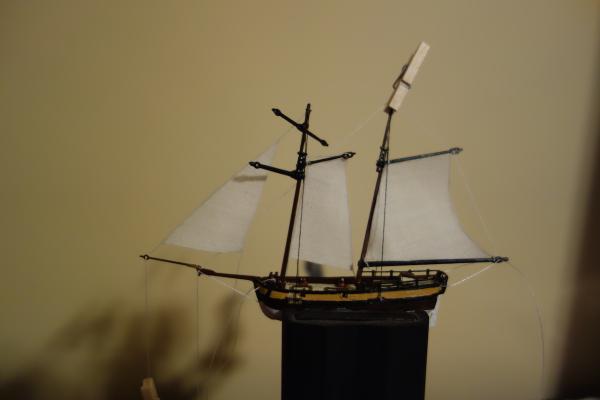
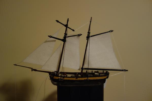
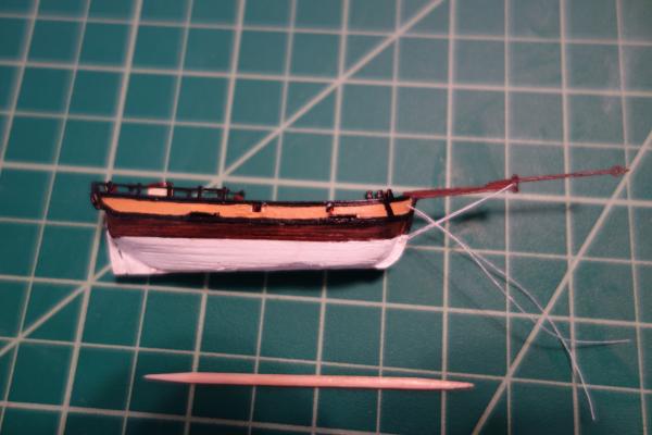
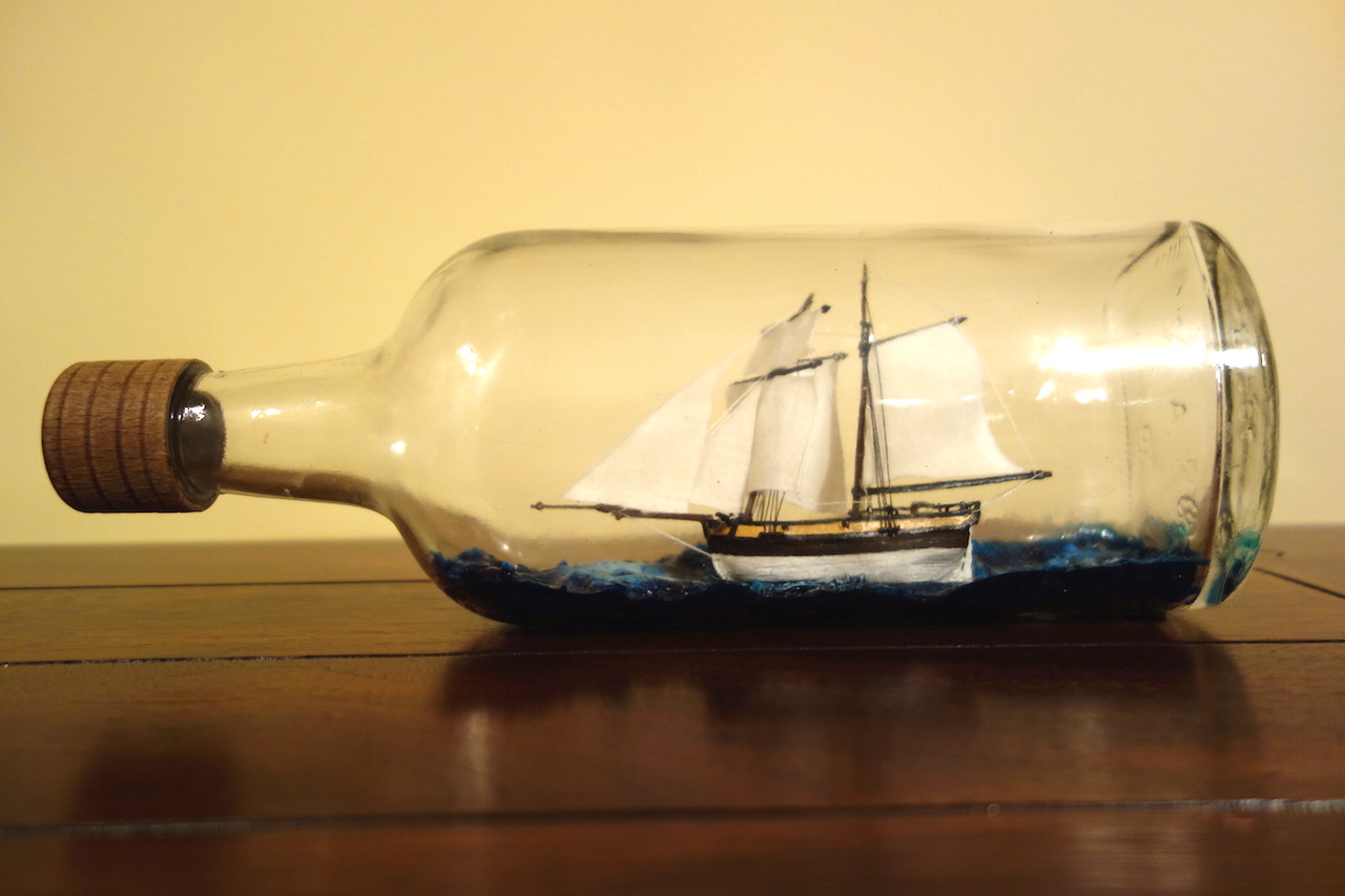
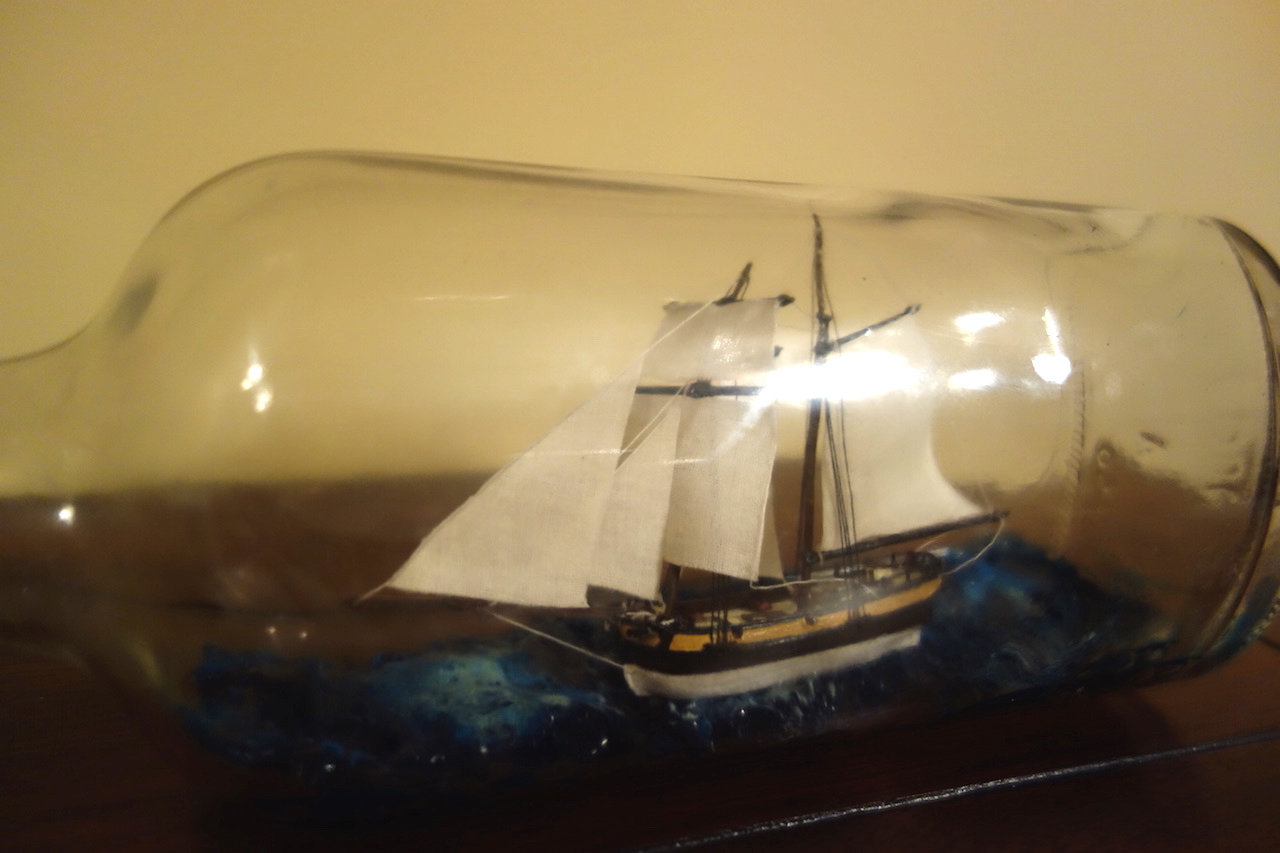
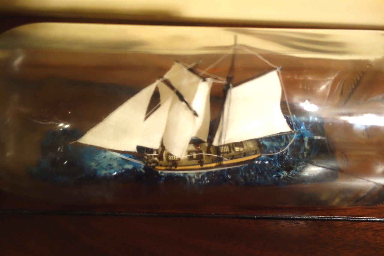
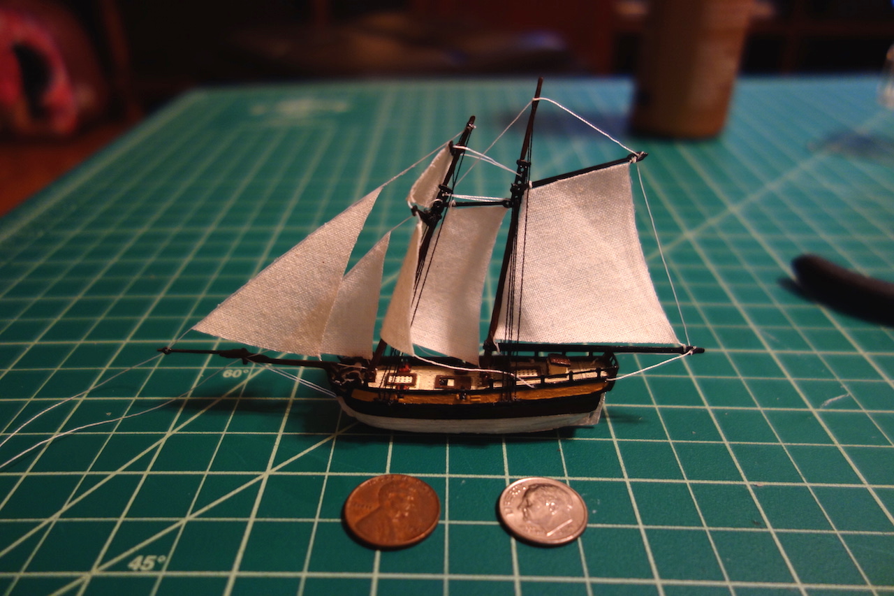
And here is the final product!

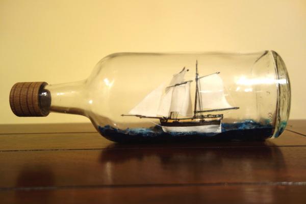
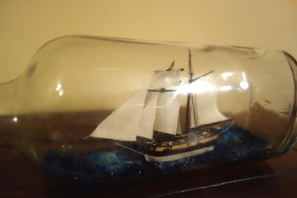
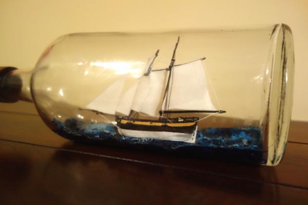

Overall, this was a very nice kit to build. It's a good introduction to ship-in-a-bottle modeling. I'm not sure if I will do any others in the future, but if I did, I think I would go fully scratch. The photo etch pieces on this model were great, but you bend them a few too many times and you are in trouble. If I had to do it over, I would also have filed more of the bottom off so that the ship would have appeared to be sitting lower in the sea. Filing off the keel was very helpful in this regard, but I think the model could have been improved if I filed another 2mm or so off the bottom.
Hmm, I do have a nice bottle of tequila that might be fun to add a model to...or at least drink while I'm thinking about it...

- Rao A.L.G., CraigVT, Griffon and 13 others
-
16
-
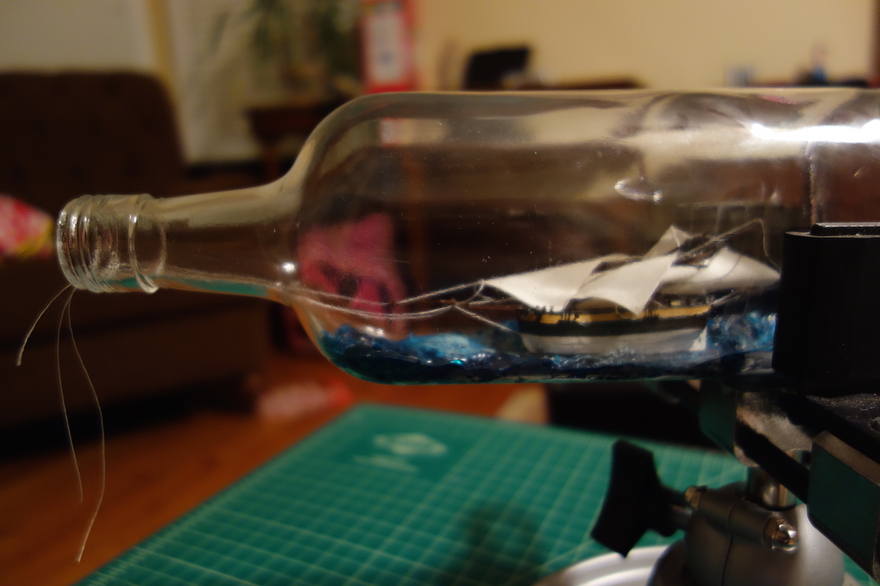
Insertion into bottle
At this point, I have the sea in the bottle and the ship is done. Next up, getting it into the bottle.
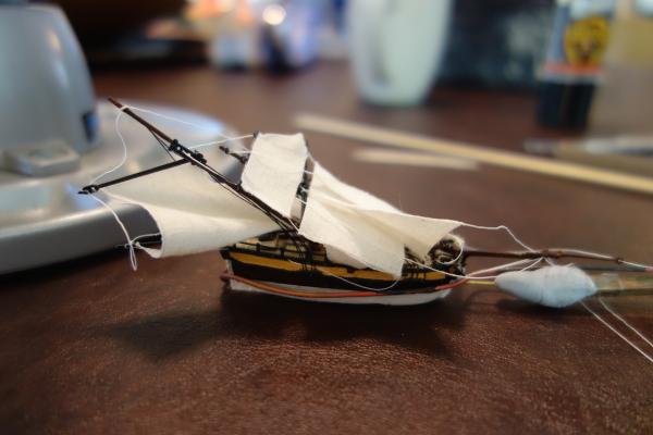
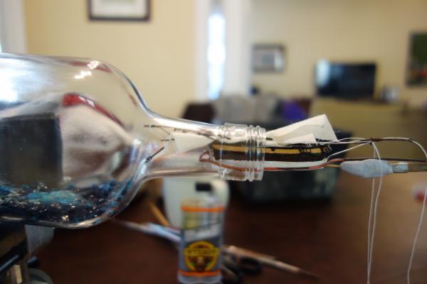
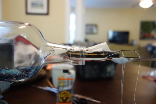
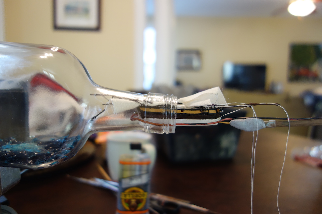
This stage was very stressful. The diameter of the opening to the bottle is less than an American quarter! So, you have to fold the masts down nice and flat to have any chance of getting it in. This process was incredibly stressful. First, I couldn't get the rear mast folded down due to the way that I ran the rigging. For some reason, the jib staysail (the inner one) was restricting the mast from fully lowering. I ended up having to cut the line from the top of the main mast, tied that line (on which the jib staysail was) to one of the spars, and ran a separate line from the top of the main mast to the exit hole.
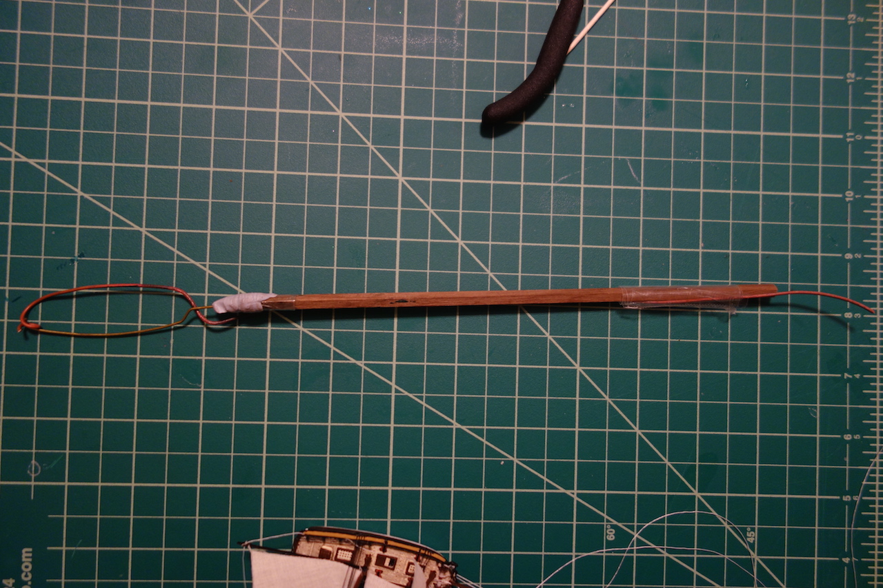
Once that issue was resolved, I tried to figure out a better tool to insert it into the bottle than the string technique the kit calls for. The model is too heavy for the string technique, which essentially involves creating a noose to go around the hull where one side is brass wire and the other, a string that completes the loop around the hull. I ended up taking a piece of annealed copper wire (which i use in my other hobby, bonsai), bent it to the same configuration as the other wire piece, and taped it to the handle. When the ship was in the bottle, I cut the tape and both sides of the tool slipped out.

The bottle opening is incredibly tight. I filed down the inside bottom edge of the bottle to help get the ship in. Because I had added the sea, I decided to file off the keel bottom. Even without the keel bottom, it was still hard to get the ship in and required heavier pressure than I thought. A lot of prayers and finger crossing as I pushed it through the bottle's neck!
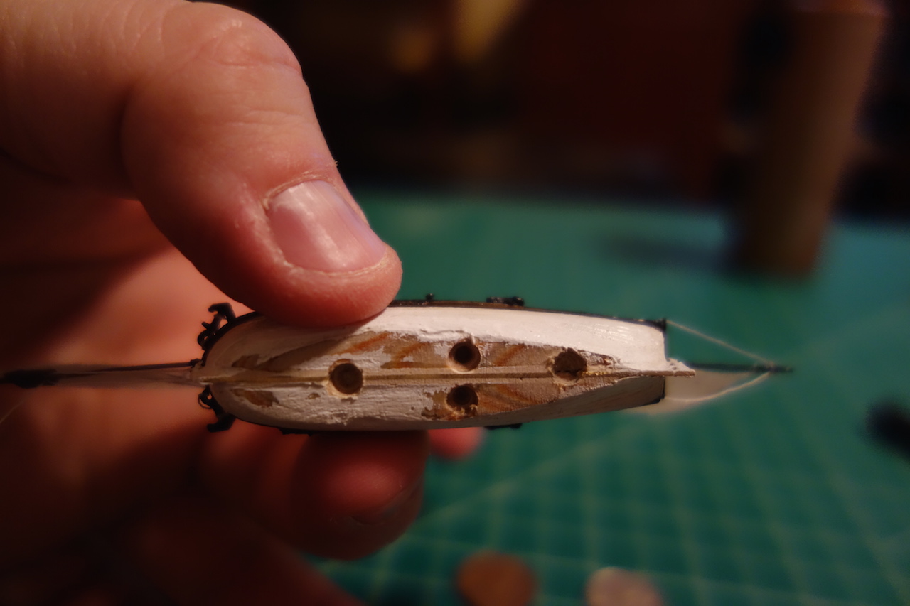
Now my goal was to insert the ship and drop it onto the pedestals. Using the pedestal base as a guide, I tried to build up the sea as much as possible outside the base. But, some of the sea got onto the base, and so I figured I would need some wiggle room with the holes in the bottom of the ship. So, I drilled larger holes to accommodate any necessary shift - since the unexpected usually should be expected. I put some 5-min epoxy into the holes and pushed the ship in.

That's where things went wrong. I apparently hadn't gotten the sea far enough from the pedestal base, so the ship couldn't sit cleanly on the pedestals. This freaked me out because the holes had the epoxy in them and I was afraid that it would leak out and get onto the sea or the sides of the bottle. So, I tilted the bottle to its side and using a long bamboo skewer, I quickly dabbed a bunch of epoxy along the pedestal bottom and sea. Thankfully, I was able to position the ship a certain way where it was able to sit on the front post, and lean against one of the middle posts at the back of the bottle. Another nerve-wracking experience, but it went without a hitch.
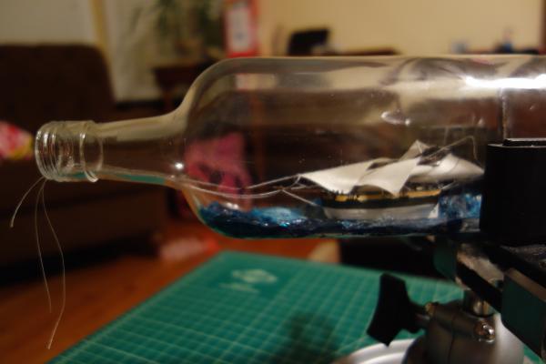
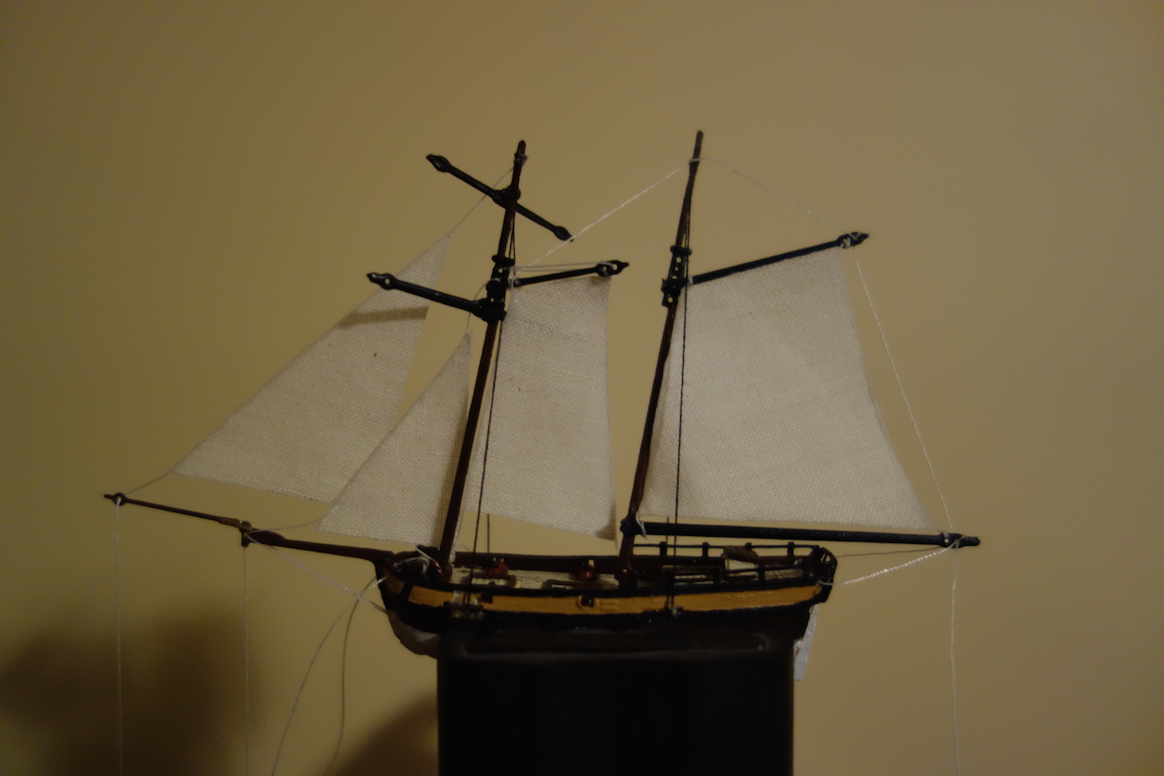
With the ship in the bottle, I raised the masts. I had one problem where the main mast was bent pretty bad. I'm not sure if this was because of the insertion, or that it came about when the masts were raised and the lines pulled taut. I was really worried that bending it back would cause it to snap. Using two putty knives with extended handles, i was able to straighten it out and again, the modeling gods were with me and it didn't snap. I had to do a couple of touch ups of glue and paint (against, stressful while the model is in bottle), but it worked out. After all the touchups and arranging the sails the way I would like to see them, I cut the cords using the blade that came with the kit (pictured below), glued the cap on and affixed the felt circles to the bottle's bottom.
[picture of tool to come]
-
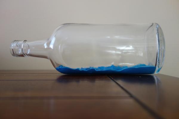
Adding "sea" into the bottle
The kit has you glue a small base with four small posts in it into the bottle. If I remember correctly, there was a decorative wood base, plus a brass photo-etch on top. I ended up just using the wood base with the posts glued onto it, and glued it to the center of the bottle while it waited for the sea. My goal was to sit the ship on the base, but build up the sea around it so that it looked like the boat was actually in the water. I had some difficulties as you can see later.
This part was the most complicated part of the build. I've seen all different methods and materials. Some use clay which is inserted like a snake and then heated so that it melts and evens out. I've also seen where others have used painter's caulk, which is somehow colored and then inserted the bottle using something similar to the method in which decorative icing is applied to a cake.
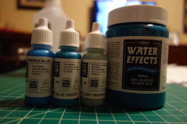
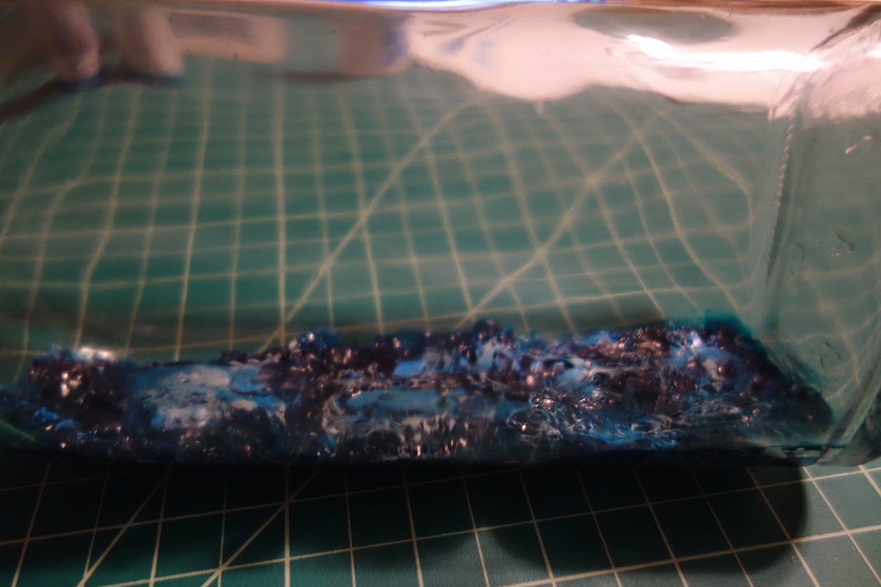
I decided to go a different way. The clay to me looks pretty fake, and is usually too blue for my tastes. I considered using Realistic Water or something similar, but decided not to (I think it was because to use it right, people usually paint the floor first, and then drop the realistic water on top - that would be almost impossible to do for a ship in a bottle). I eventually came across Vallejo's "Water Effects" - as you can see in the picture below, I picked the Atlantic Blue.
The Vallejo Water Effects has the consistency of yogurt. It was a real pain in the *insert body part of choice* to get it into the bottle. I ended up using a small putty knife to drop it into the bottle. The trickiest part was getting it evenly close to the neck of the bottle. Of course, I would accidentally touch the glass and then have to try and get it off - not as easy as it sounds!
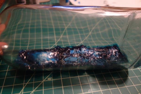
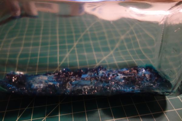
I also noticed that the stuff forever to dry inside the bottle. The first layer I applied in 2012 was dry. But the stuff I applied in early February of this year was still wet 3 weeks later! I found that it dried when heated. As you can see in the pictures below, the material out of the jar is like a french blue, then when dry, it darkens to a deeper, dark blue. So, I tried it in the oven. At 250, it didn't seem to do the trick. Finally when I got to 325, it changed to dark blue almost immediately. The problem though is that at that temperature, it started bubbling in the bottle, and I ended up with a few "pops" where there was material all over the glass sides. What a pain! It also smells a bit when it is baked, so when I removed the bottle, I sat it next to an exhaust fan while it cooled off.
Once done, I used the Vallejo paints in the post above to add some colors and highlights to the water. Used a dry brushing technique starting with the darker colors and going towards the lighter colors. I also bought a foam/snow effects bottle from Vallejo to simulate the white caps, but it was very stark white and I think went on a little thicker for volume. The light green-blue color gave me the effect I wanted, so I stopped there. Again, tricky near the neck of the bottle, and I seemed to always bump the paint brush against the glass.
-
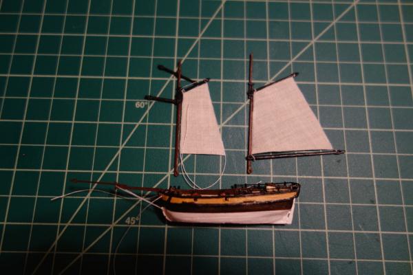
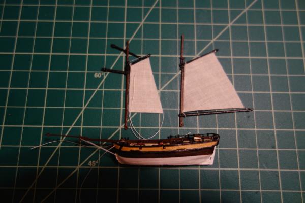
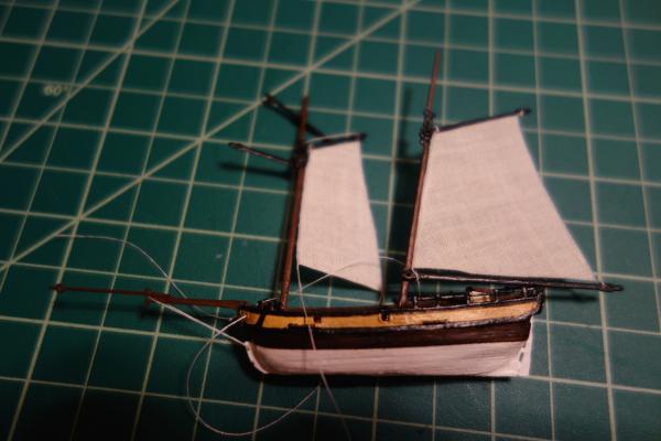
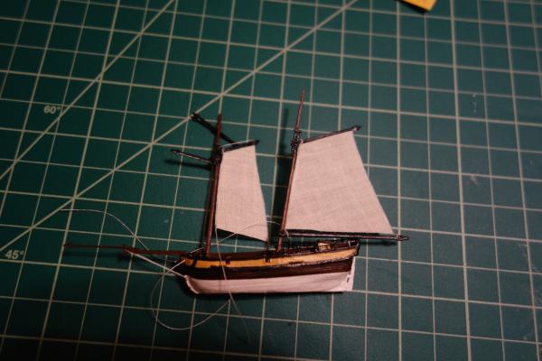
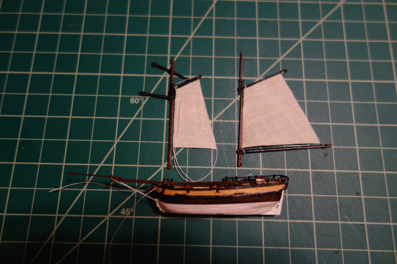
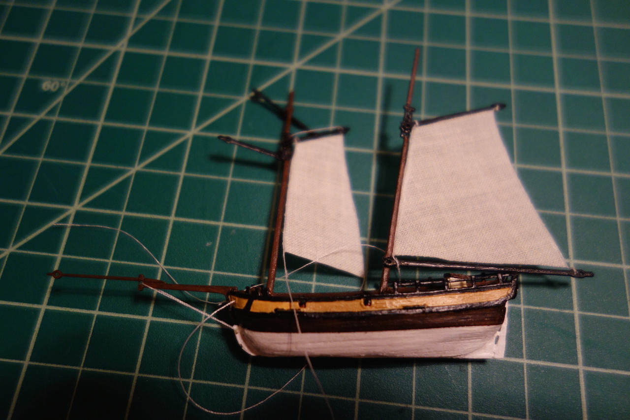
Sails
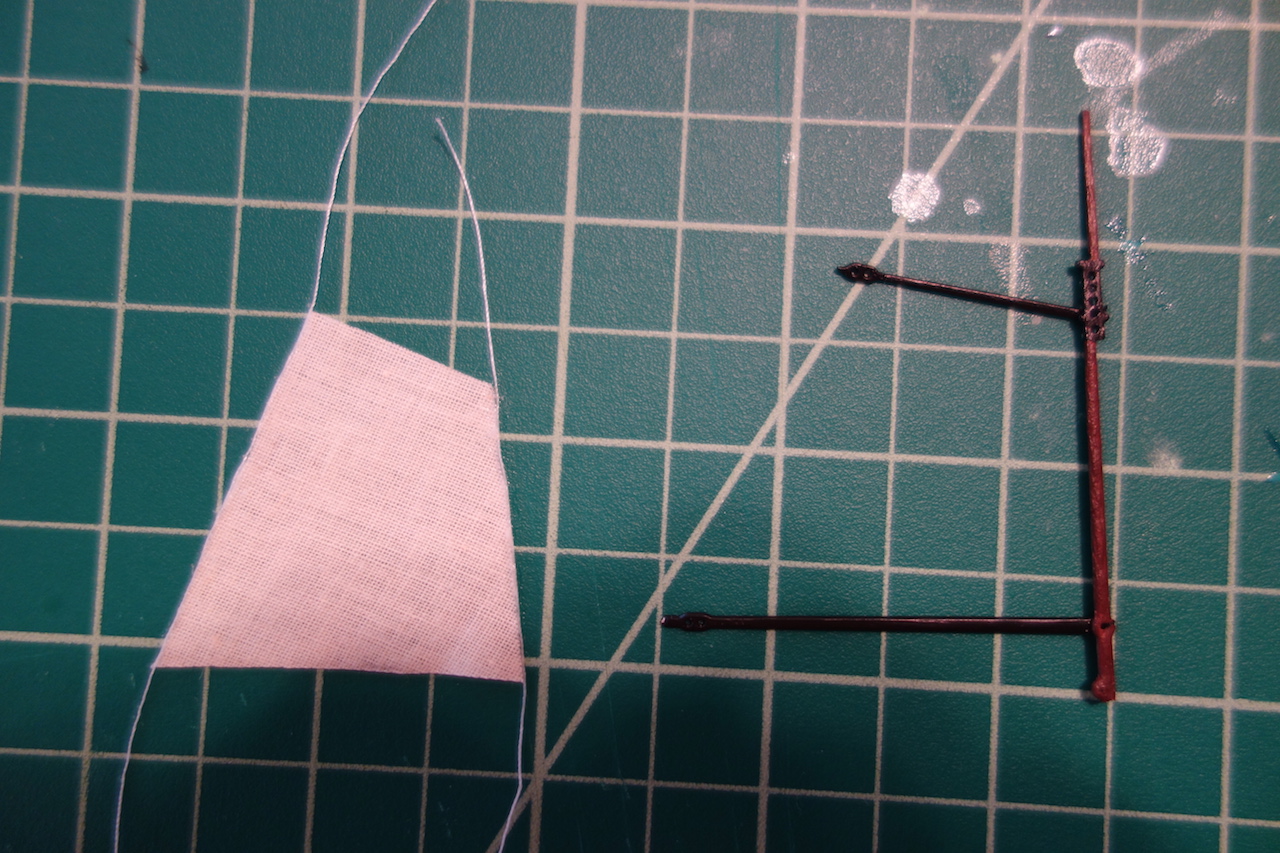
I deviated pretty substantially from the kit on the sails. First, I ended up replacing the kit sails as I didn't like the printed seams, etc. for the sails. I used some very thin fabric that I think came from Model Expo. Probably a bit thick, but it worked ok. Rather than sew the sails on, I used Aleene's fabric glue to glue the lines to the sails as appropriate.
The masts and spars are created from photo-etched parts. The parts are very nice, but be careful with the parts, particularly the masts and bowsprit. The brass holds up fairly well, but I accidentally bent the bowsprit a few times and eventually, the part just snapped. It was a real pain to glue back together - I ended up gluing it back on with CA and two thin strips of brass on either side to hold the joint better, but still snapped it another half dozen times. I was really worried that it would snap in the bottle -- and consequently would ruin the bottle as there would be no way to glue it back -- but the modeling gods were with me and it stayed firm.
The rigging plan is pretty well diagramed and explained in the kit's instructions. The kit comes with white line, but I decided to use black Gutterman sewing thread for the shrouds.


-
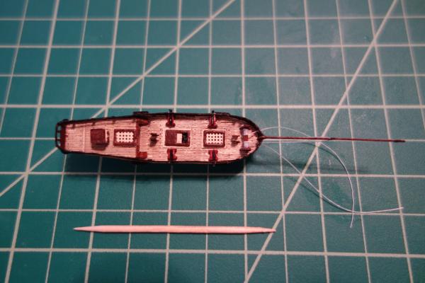
Construction of the Hull
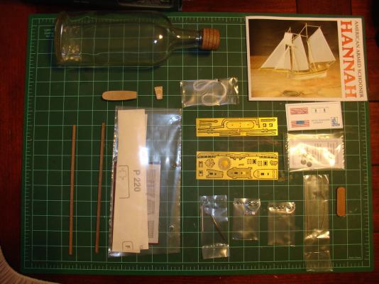
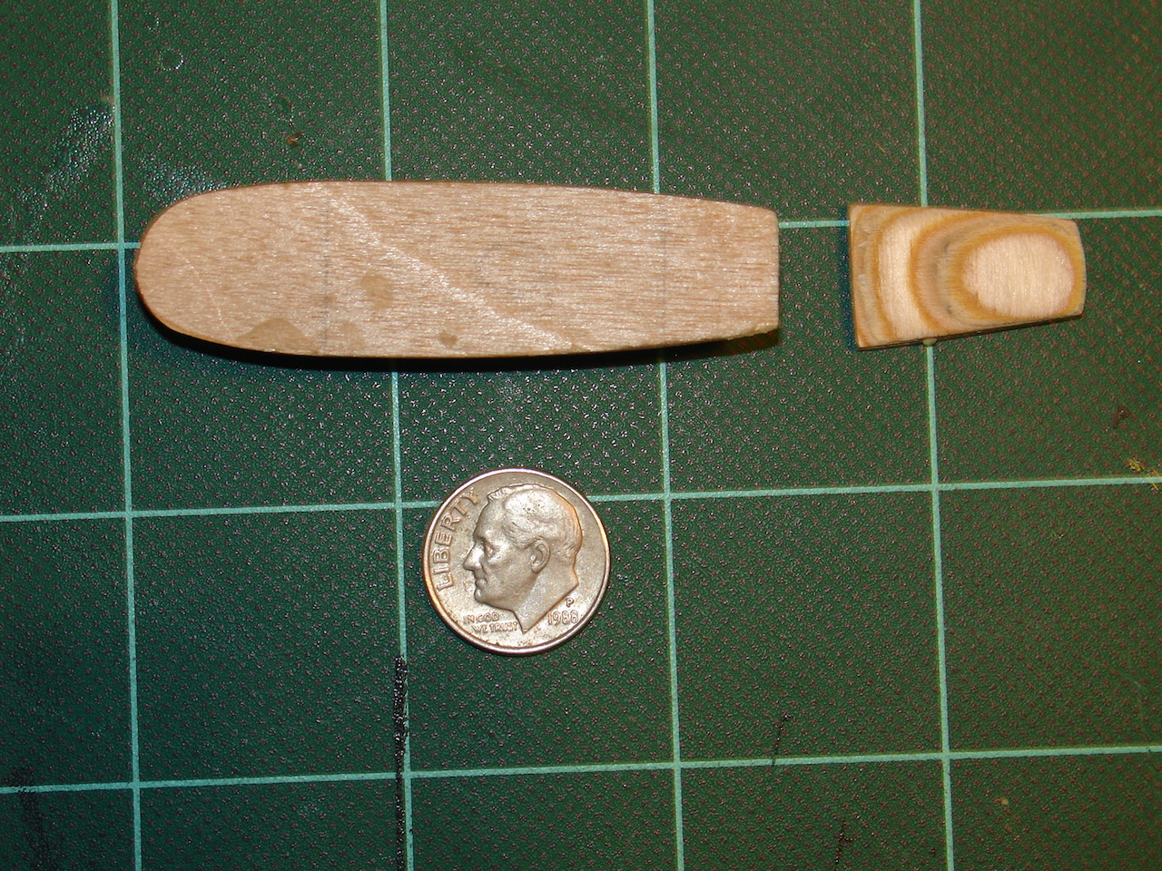
The kit is 1:300 scale, which is incredibly small. For scale, here is a picture of the hull compared to an American dime:
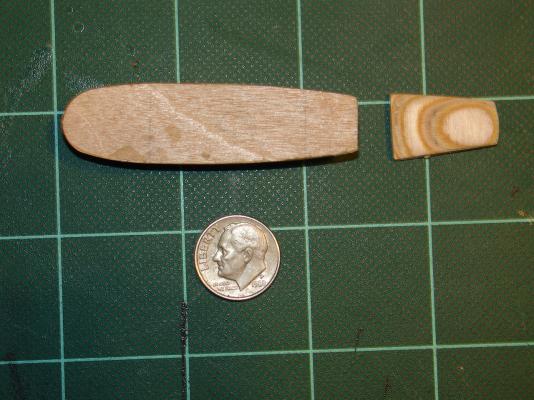
The hull is constructed by a "bread and butter" technique of layering multiple thin pieces of wood together. The deck, masts, spars, keel, hatches etc. are all photo etched parts. Some of the detail pieces like the anchors, deck house and cannons are cast metal pieces. The cast metal pieces were surprisingly very nice at such small scale.

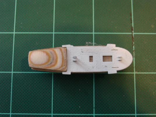
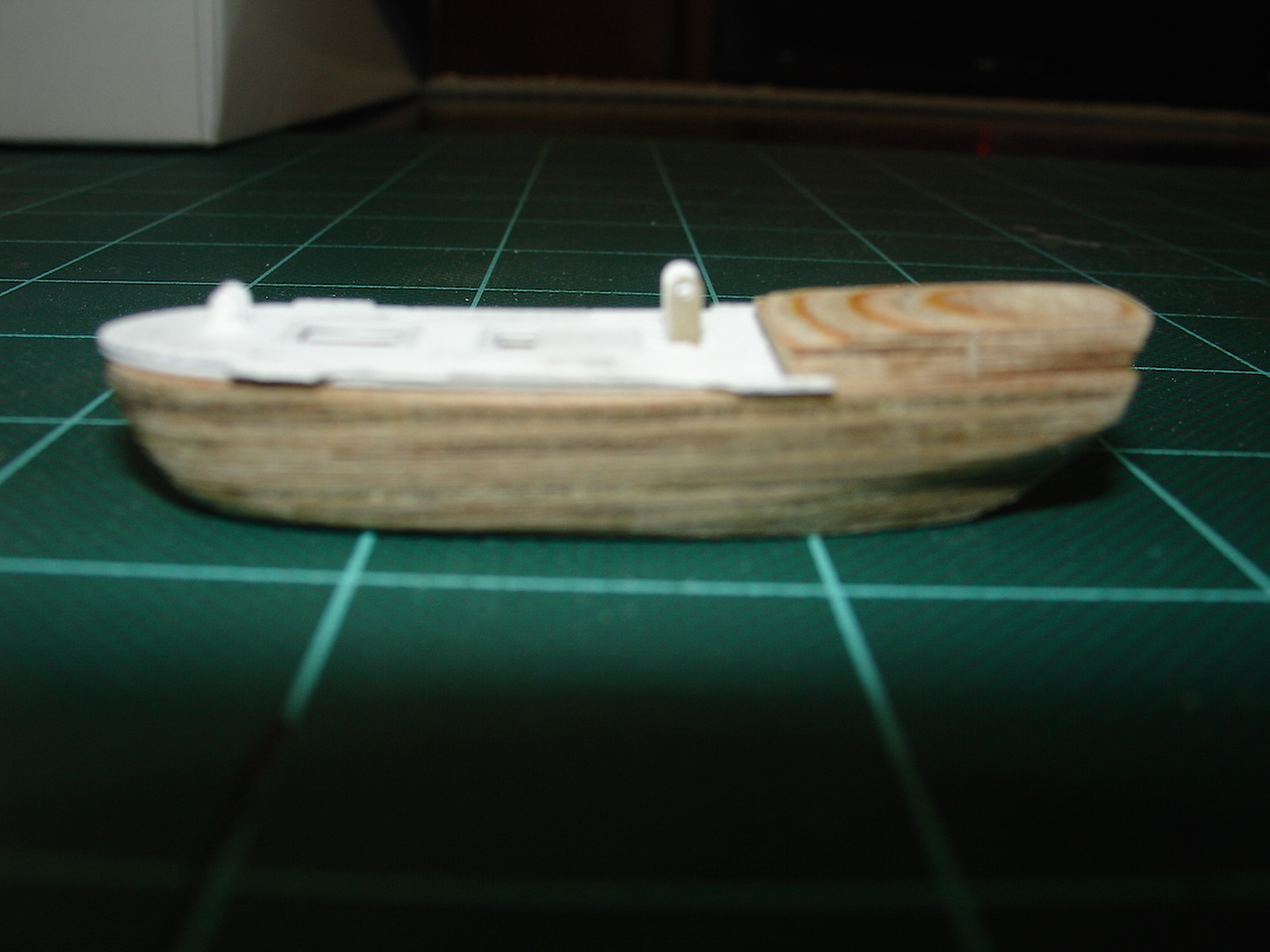
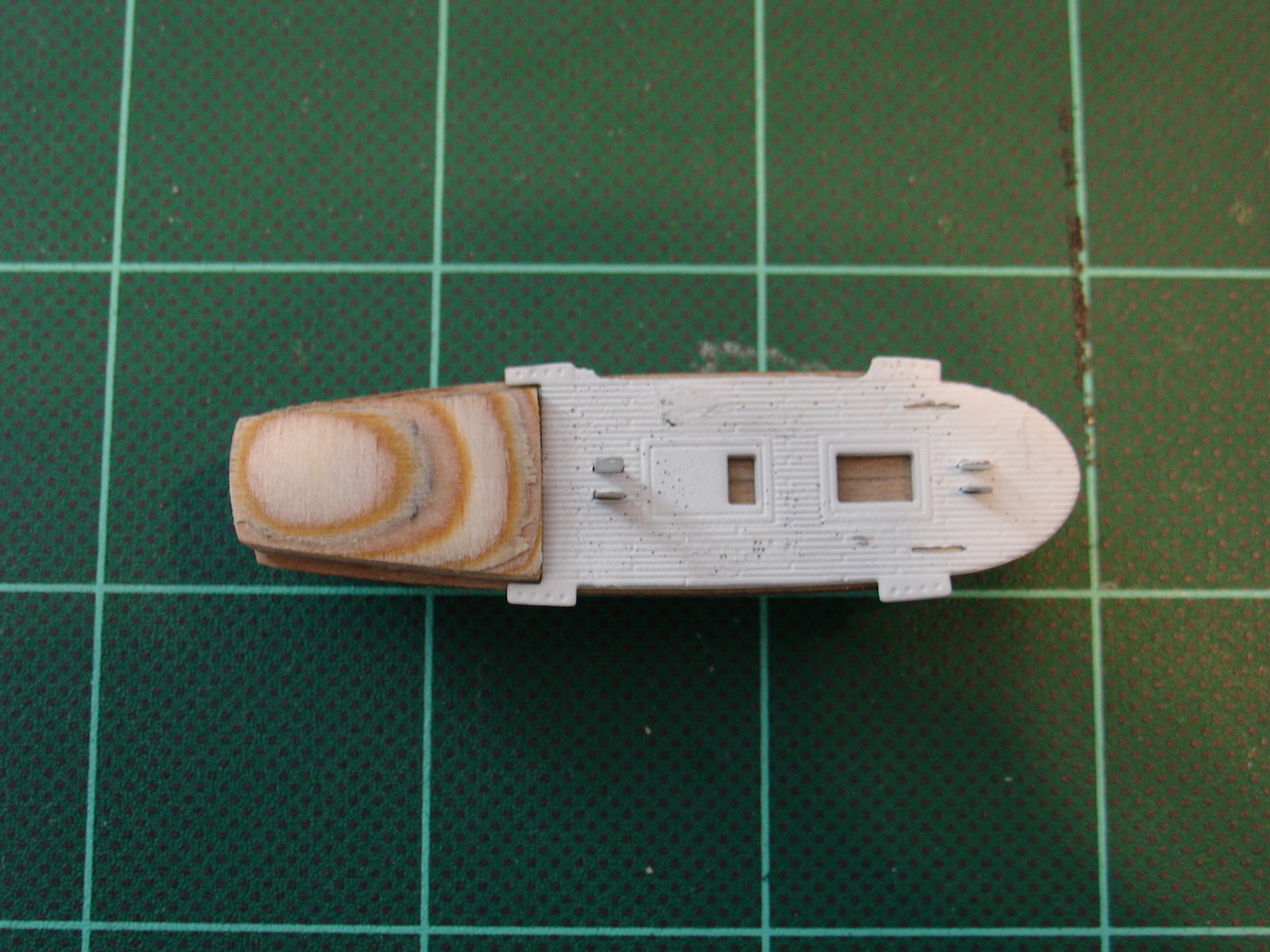
You can see that I decided to paint the ship. I used walnut stain on the wood area, and paints for the rest. Once complete, I used a matt varnish from Vallejo to seal things. I had a really rough time getting the keel around the hull. I actually had to break it into two pieces so that it fitted nice.
-
Today I finished my Hannah Ship in a Bottle kit from Amati. I picked it up on a whim off of eBay for $20 a few years ago thinking it might be a fun little project. I spent a few weeks on it during my Badger build in the summer of 2012 to give me a mental break from that model, and then the model sat for the next two and a half years. I picked it up again this year, spending the last month or so finishing it as a break from my Pegasus build. I decided not to do a build log as I went along, as frankly, I was a bit worried that I'd screw up the project and have to scrap it due to my modifications - in particular putting sea in the bottle. So, rather than potentially embarrass myself, I decided that I would post one at the end if things turned out ok. The good news is that it all worked out in the end and so here is a summary log with pictures I took along the way.
Introduction
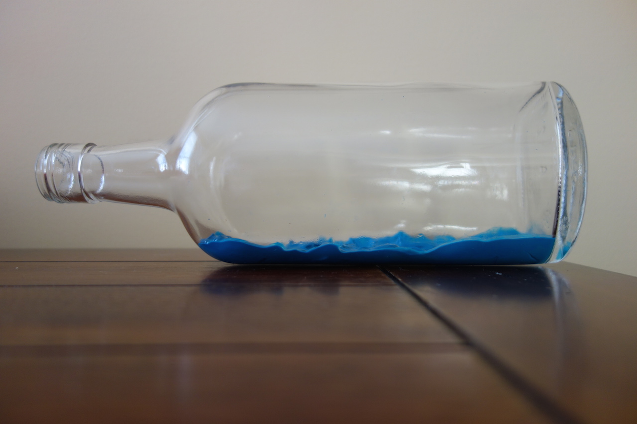
The kit is quite nice, with very nice photo etched parts, a nice bottle, and pretty good materials. The instructions are also pretty good. The folks from Amati are incredibly nice as well, as I somehow lost the keel part but they sent a new photo-etched set for free - thank you Amati!
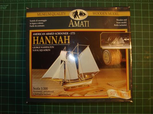
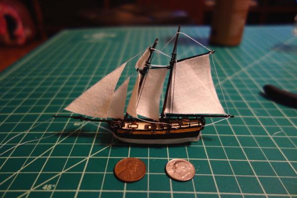
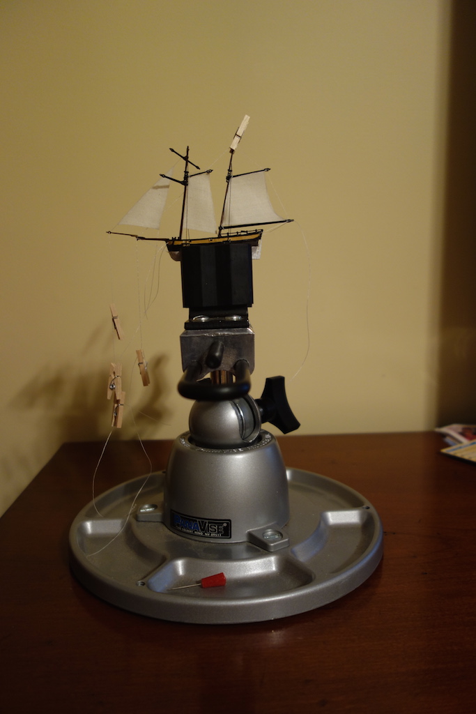
As you can see in the picture below, the kit is designed to have the ship sit in the bottle on a stand.
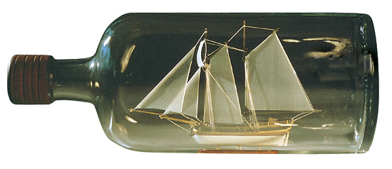
I decided that was a bit plain, and made the following modifications:
1. I painted and stained the ship, rather than leave it in brass.
2. I replaced the kit sails, which were dyed to show seams, with plain cloth. I thought the seams, etc. on the kit sails were a bit out of scale and garish for my tastes.
3. I added "sea" to the bottle.
Adding the sea really complicated the build, but I think it came out pretty nicely. The next few posts go into the construction process.
-
Hi Max,
The FWZP is an amazing kit, isn't it? The plans and cast pieces are nothing short of incredible. I too was surprised at the weight! I'm probably a good 5-10 years away from starting that kit unfortunately, as I have my current Pegasus and Lyme builds going, and also have the Charles Morgan on the shelf as well. I think once I get through those kits, I'll hopefully be ready for the FWZP

-
Hey Carl, not sure if you already got your model into the bottle or finished it. I got my model into the bottle last night and raised the masts. I need a little more time tonight to arrange the sails a little better and she will be done. It was getting late, and I didn't want to make any mistakes from being tired or otherwise rush it.
I'll try to post my log tonight, but if I can't get to it, I just wanted to pass along a couple of tidbits. The insertion process is very stressful! First, I couldn't get the rear mast folded down due to the way that I ran the rigging. For some reason, the jib staysail (the inner one) was restricting the mast from fully lowering. I ended up having to cut the line from the top of the main mast, tied that line (on which the jib staysail was) to one of the spars, and ran a separate line from the top of the main mast to the exit hole. So, make sure your masts can be fully folded down.
Once that issue was resolved, I tried to figure out a better tool to insert it into the bottle than the string technique the kit calls for. The model is too heavy for the string technique in my experience (or it needs perfect execution to work). I ended up taking a piece of annealed copper wire, bent it to the same configuration as the other metal piece, and then taped it to the handle. When the ship was in the bottle, I cut the tape and pulled out both halves of the tool.
The bottle opening is incredibly tight. I filed down the inside bottom edge of the bottle to help push it in. Even then, it required heavier pressure to insert than I was expecting. It was that tight even with the fact that I had sanded off the keel bottom since I added sea to the bottle. Once inside the bottle, I used the insertion tool and other tools to pull the masts up and position the sails. Be careful to do it slowly, and watch for any bent masts, The top of my main mast was bent somehow through the process, which was a little tricky to straighten out. The bottle is pretty narrow inside, making any tool work pretty tricky. The key I think is to make sure the ship is firmly glued to the bottom of the bottle so that you can pull the masts up.
Anyway, don't mean to scare you or anything, just wanted to make sure that you were prepared. I'll let you know when I get my log up, but otherwise, let me know if you have any questions.
-
-
Last summer, I ordered one of the Euromodel figureheads from Euromodel for my Lyme build. They were incredibly courteous, and shipped it out the same day before they went on an extended summer holiday. Impeccable service and very nice people. I am really looking forward to building the FWZP in the future (which is sitting on my shelf) in part because of their service - their kits are also beauties themselves too!
-
Beautiful work. I've always thought the Niagara was the perfect ship to add full sails to. Your work is fantastic!
-
Looks fantastic Nils. I'm glad you went with full sails - you've convinced me to try full sails on my Pegasus as well.
-
Thanks Hamilton for that link. Carl, I had the same experience with the insertion tool that the guy in the thread above had as well. I'm thinking about other alternatives like blue-tac or something else.
-
OK, OK...
In current order of likelihood, which could change tomorrow.
MS Charles W. Morgan
MS Brig Niagara
MS Brig Syren
Caldercraft Cruiser
I'd build the USS Constitution from the MS kit in a heartbeat, but even in that scale I can't imagine where I'd put the beast.
Great choices Joe. You'll definitely do a fantastic job on any of those kits for sure.
I have the Charles Morgan kit. It's a nice kit with detailed plans, and as John's build shows, it makes for a very nice model. I'm looking forward to building it one day as something different from a war ship. No fiddly cannons to deal with, but seven whaleboats and lots of interesting whaling-related items to build instead. Some of the kit's included pieces are not very well done though - I think you'll find that you'll need to scratch quite a bit, as John shows on his log. Otherwise, I think it's a great kit and it's nice that the ship is available to see up in CT. I'm planning to eventually do mine in full sail, as I think that would really make the model look magnificent if I can pull it off. I think the Niagara would be another beautiful ship to do in full sail too. The nice thing about the Niagara is that you can just buy the plans if you are planning on replacing the kit wood.
Constitution is another nice one. My wife thought my Badger at 2' or so in length was big, and raised her eyebrows when I said my current builds are around 3' long. I can only guess the reaction if I told her my next build would be 4' in length
Have you taken a look at the Euromodel kits? They are a bit pricier than the other kits you are looking at, but in terms of plans and kit components, they are really nice kits. I managed to get the Friedrich Wilhelm zu Pferde off eBay for a steal, and it's an incredible kit. What I like is that the kit plans give you enough information to add lots of extra details to your build. There are also detailed practicums that are available for free to help one along. I'm saving this kit for last after my other kits to get my skill level up to really do it justice.
Looking forward to whatever you decide!
-
Looking great Joe. You're moving along quickly but with excellent results. You're going to need to start planning your next build soon
-
Really incredible work Ian. Thank you for the tutorial. Even more impressive when considering how small these parts are!
I should have paid more attention in math class


Hannah by Landlubber Mike - FINISHED - Amati - Scale 1:300 - BOTTLE - kit bash
in - Kit build logs for subjects built from 1751 - 1800
Posted
Thanks for the kind words Hamilton. I'm looking forward to your Hannah as you already have a knack at working at small scales.
As for the 1-page build log, that probably because I didn't want to embarrass myself by posting a progress log during the build, only to fail in the end. Once the ship is in the bottle, it's not coming out. I was really worried that I would break the bowsprit off again, and when the main mast got bent, there was a lot more finger crossing and colorful language Those would have been repairs that would have been impossible to make.