Landlubber Mike
-
Posts
4,554 -
Joined
-
Last visited
Content Type
Profiles
Forums
Gallery
Events
Everything posted by Landlubber Mike
-
 Very nice work Martin. I like the use of the specialty wood - it gives a nice red color
- 467 replies
-
- 1
-

-
- fly
- victory models
- (and 1 more)
-
The golden mean sounds like a good one. I'm trying to use as much of the kit as possible too, but it seems like I find more stuff to replace. I just placed an order with Jeff at Hobbymill for the Pegasus and for some supplemental wood for my Unicorn, and the cost does add up (thankfully, I've paid significantly below retail for these kits). I think once I finish the kits on my shelf, I'm going to move towards buying good plans and go into scratch building. My Unicorn is almost looking like a complete scratch build outside of using the kit bulkheads
-
Hi Martin, I believe that I bought the General Finishes stains from Woodcraft (online). They have lots of different shades, as you can see here: http://generalfinishes.com/retail-wood-finishing-products My best success for the black was using the "stain", rather than the "dye stain." Maybe I needed to stir the dye stain a little more. They have some interesting colors for ship building. For example, they have a yellow that seems like it could work nicely as a yellow ochre replacement. The great thing about using stains is that you don't get that painted on texture. Some people thin down paints and paint 20-30 coats, but I'd rather put on one or two coats of stain and be done. I'm not sure what I want to do with the bulkheads yet. The downside of stains is that you don't get an even color across different wood types. I'm thinking of removing the bulkhead extensions, and replacing them with stained wood of the same type that I will use for my bulwark planking and cannon carriages. Still thinking about whether to do that before the hull planking, or after it.
-
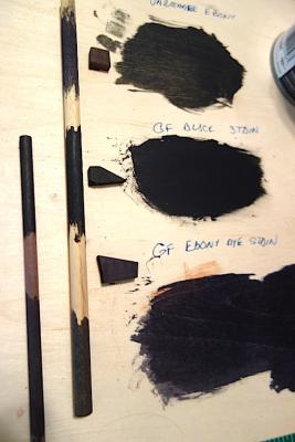
In my quest to avoid using paint, I spent a little time experimenting with some black stains and dye stains that I had samples of - Varathane 'Ebony', General Finishes 'Black" stain, and General Finishes 'Ebony' dye stain. I also have a small amount of Fieblings Leather dye, though we all know that works well to dye pear so I didn't test it. It's always hard to accurately get the full effect of color on a digital picture, but here is a picture of the test - the big board is plywood, the small pieces are scrap pear, the longer dowel is from the Corel Unicorn kit (I think beech) and the smaller dowel is from the Pegasus kit (ramin). I didn't bother to test the Varathane on the smaller dowel as it didnt have as much penetration as you can see. The results of just trying one coat are interesting. The GF black stain worked the best - very deep black that looked like the wood had been painted. The Varathane and the GF dye stain were more like your typical stain effect, where it mostly highlighted the grain. I would have thought that the GF dye stain would be the best, as GF markets the dye stains as having deeper penetration. Maybe I needed to mix it more, I'm not sure. I really like the GF black stain - you end up with a deep painted look, yet the wood texture is not hidden under a layer of paint. Just the look I'm after. In any event, I thought I would share in case others are interested in a black look without using paint.
-
In my quest to avoid using paint, I spent a little time experimenting with some black stains and dye stains that I had samples of - Varathane 'Ebony', General Finishes 'Black" stain, and General Finishes 'Ebony' dye stain. I also have a small amount of Fieblings Leather dye, though we all know that works well to dye pear so I didn't test it. It's always hard to accurately get the full effect of color on a digital picture, but here is a picture of the test - the big board is plywood, the small pieces are scrap pear, the longer dowel is from the Corel Unicorn kit (I think beech) and the smaller dowel is from the Pegasus kit (ramin). I didn't bother to test the Varathane on the smaller dowel as it didnt have as much penetration as you can see. The results of just trying one coat are interesting. The GF black stain worked the best - very deep black that looked like the wood had been painted. The Varathane and the GF dye stain were more like your typical stain effect, where it mostly highlighted the grain. I would have thought that the GF dye stain would be the best, as GF markets the dye stains as having deeper penetration. Maybe I needed to mix it more, I'm not sure. I really like the GF black stain - you end up with a deep painted look, yet the wood texture is not hidden under a layer of paint. Just the look I'm after. In any event, I thought I would share in case others are interested in a black look without using paint.

-
Hey Jason, thanks very much. I definitely could adjust the stem by lowering the seat a bit for the figurehead. I need to take a closer look at it, but it might be a crest or shield or insignia or some type. It might be a bit tricky to lower the seat, but I think it could work. Or, I could just build another stem
-
Thanks SpyGlass. The barrels do seem a bit on the shorter side. The test carriages that I stained didn't take the stain too well. I might try a sanding sealer (I think that's what it's called) for better results.
-
Really gorgeous work Mark. I was just going through your galleries - you are very skilled, thank you for sharing!
-
Thanks John and Ian! I'm not sure what I want to do with the quarterdeck guns. I haven't found much info on the 3-pounder guns - I assume they are just smaller versions of cannons on carriages? I bought from CMB some smaller Caldercraft cannons and carriages, along with smaller versions of the Corel cannons, which might work. With the tiller on the quarterdeck, I imagine that the 3-pounders would be placed somewhere along the first three or four portholes. The fourth porthole might be a bit dicey with the mizzen mast almost in the line of the portholes.
-
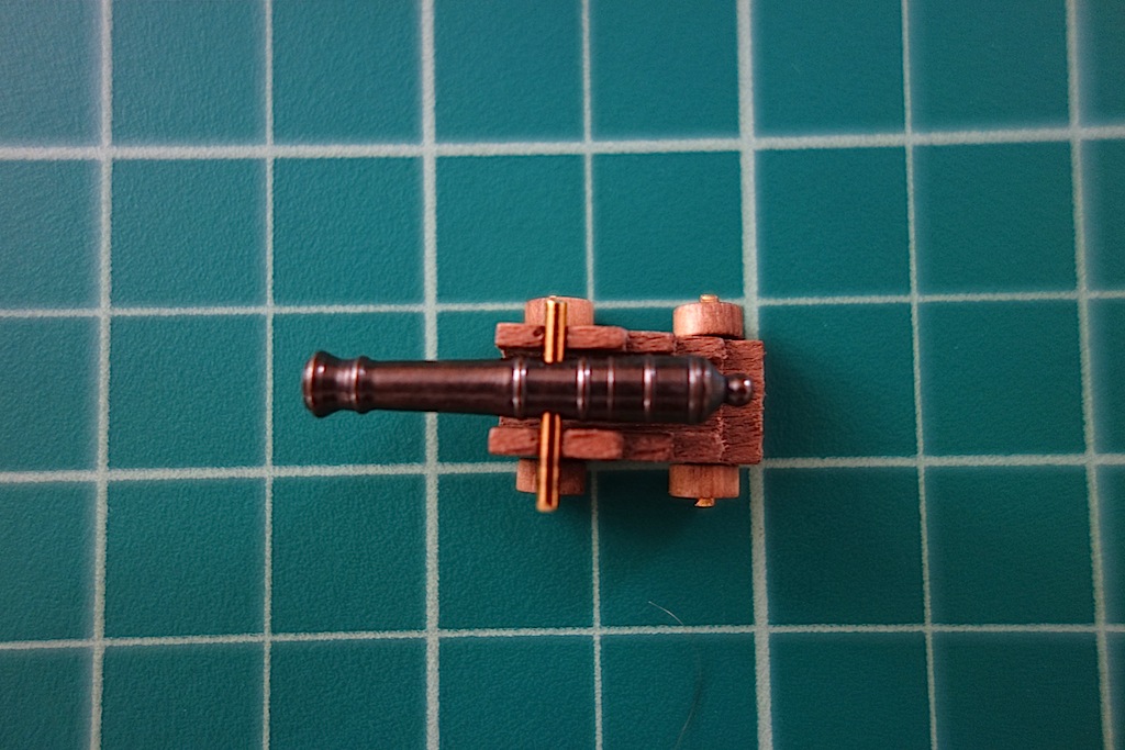
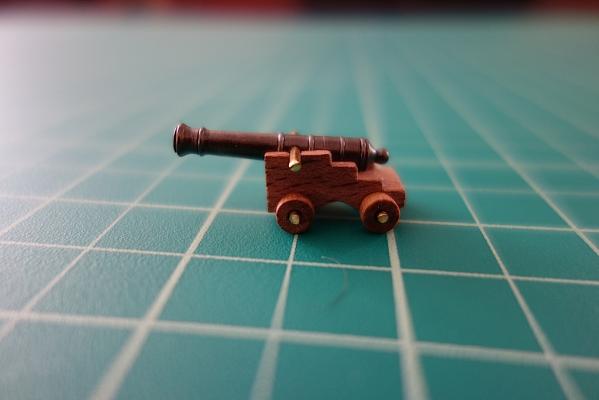
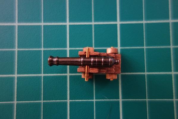
I've been playing around with the upper deck template, and put together a cannon just so that I can make sure that the upper deck sits correctly. On this kit, the bulkhead extensions have notches in them to mark the upper and lower edge of the cannon ports. While dry fitting, the upper deck template seems to be at the right height at the front and rear of the ship as the gun fits right through the middle of the framed section, but the middle seems a bit too high. I have to figure out whether this means that I need to file down the middle bulkheads so the deck template sits lower, or whether I need to run the frames at a different height from the bulkhead notches. I think this will depend on whether the bulkheads are at the right height or not. It could all just be a matter of filing the edges of the deck template so that it fits a little flatter. Unlike the vast majority of the kit that I am scratching, I have been planning on using the kit's cannon carriages as they are in one solid piece (so not as much construction) and seem to be very clean parts. I plan on using red stain on them as in my earlier pictures, and using walnut for the the bulwarks and similarly staining them. In taking a look at the test cannon, it seems like the cascable sits a bit more forward on the carriage than I would have thought. I took a look at the guns on my Badger, and the cannon cascabels are pretty much in the same location. But, in looking at other pictures, the cascabel is at the very end of the carriage or even extends beyond it. Here are some pictures: I'm curious if others have a strong reaction on the accuracy of the cannons. In some respects I'm not too concerned as most of the cannons will be hidden, even at the waist when I add the small boats. I'm also not planning on adding the 9-pounders to the quarterdeck, as the ship originally started out with 24 9-pounder guns on the upper deck, and only later (in 1756) were the four 3-pounders added to the quarterdeck. Instead, I will add the tiller and maybe some swivel guns to the quarterdeck.
-
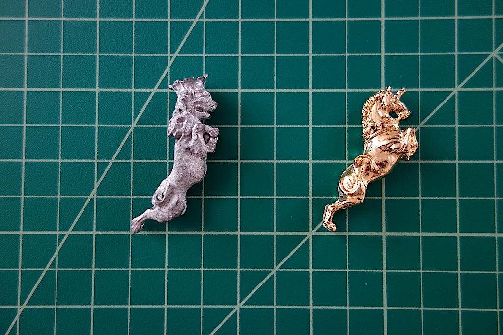
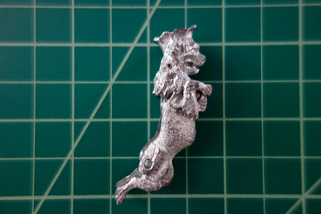
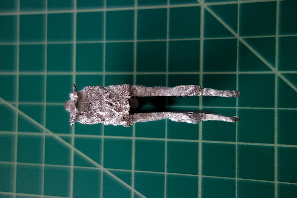
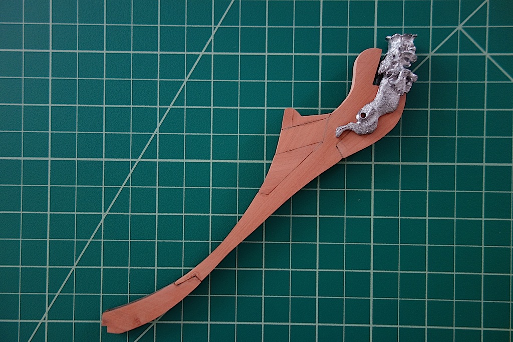
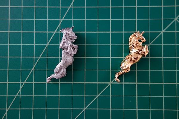
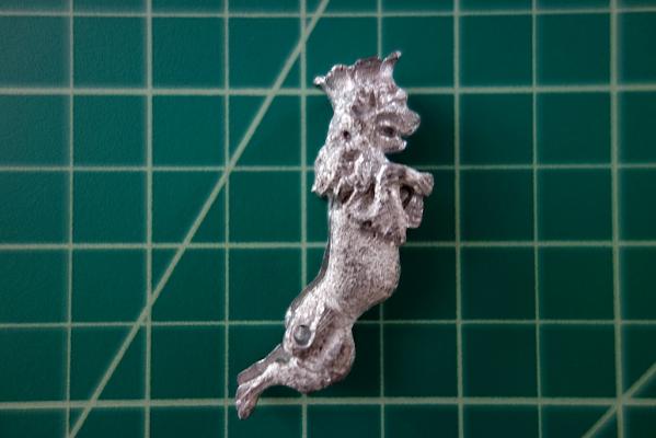
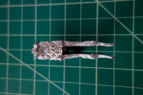
One other difference between the two ships is the figureheads - the Lyme's is a lion. I might try scratching a figurehead, but in the event that I fail at producing a good enough one, I searched around for a suitable figurehead as a backup. It was a bit hard to find one that was the appropriate size and style, but I ended up ordering the Mordaunt figurehead from Euromodel. They were kind enough to let me order one even though I didn't meet the minimum order requirement on their website. And to boot, I got to correspond with Peter on here who lives in Australia and helps out on customer service - a really nice fellow who has been kind enough to post his practicums on the Euromodel website. Well, the figurehead arrived today and looks like it will work perfectly! I will likely need to tweak the stem a bit and maybe the figurehead a tad as the lion is holding something between its paws that I might consider removing (and a crown as well, that I might think about removing), but overall, it looks like it will work out very nicely. Most importantly, the figurehead comes with a cut out in the back and bottom to slot it onto the stem. The cut out is 5mm wide, so it fits my 5mm stem perfectly. The problem with the Unicorn figurehead is that in some areas, the figurehead is 5mm or less in width, making it harder, if not impossible, to cut a slot to fit it onto the stem. So, the kit's instructions have you simply glue it to the front end of the stem, which is not really correct as figureheads sat on or straddled the stem. It's rare that things work out so nicely like that, so I'm very happy right now. Here are some pictures showing the details of the figurehead relative to the Unicorn's figurehead (minus half a horn!), and also a test fit on the stem. The figurehead should actually sit a little lower, but the thing between the lion's paws is preventing it from moving further down. But, this gives a good idea of what the figurehead will look like.

-
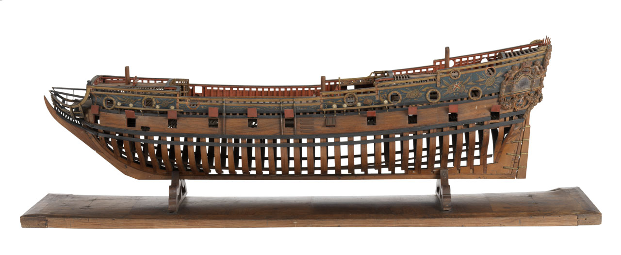
So, I made the decision to build the ship as the HMS Lyme, the sister ship to the Unicorn of the Lyme Class (the Unicorn and the Lyme were the only two of the class). Although I liked the idea of building a beakhead ship, I decided on the Lyme for a few reasons. I liked the shape of the galleries of the Lyme, which have less of the cathedral look than the Unicorn (and I think they would be easier to scratch build), and I liked the transom decorations a little more. The fact that I have the NMM plans also makes me more likely (hopefully!) to build a more accurate model. Finally, building the Lyme with the full plans helps me to avoid some of the issues associated with the Corel kit - namely, the fact that the first bulkhead is too far back as Ian pointed out, and what to do on the quarterdeck rails, or lack thereof. Of course, another good reason is that I think I will have the only Lyme out there, and so my work won't be compared as easily to the really good work of Ian, John, ZyXuz, Olly, Peter, etc. - or at least I can always use the excuse that I'm building the Lyme and not the Unicorn
-
Hi Frank, hope you are feeling better. Really gorgeous work. Is the lighter wood you used for the upper hull planking from the kit? I have a Corel Unicorn kit that I'm working on where I'm going to go with pear for the hull planking, but in seeing your pictures, I'm going to have to save those planking strips in my kit (if my kit came with them) for another build
-
Where is a good place to buy from? - moved by moderator
Landlubber Mike replied to wdretired's topic in Wood ship model kits
It might help knowing what ships you're thinking of. I've bought directly from Caldercraft and Model Expo before with no problems whatsoever. I also have ordered parts from Cornwall Model Boats in the UK, and have had a very good experience with them as well. -
Hey Ian, welcome back. Thanks for all the tips on the small boats. Interestingly, the AOTS Pandora shows the ship with five small boats - a 28' pinnace, a 24' launch, two 22' yawls and an 18' jolly boat. Going from port to starboard, the ships sat three abreast in the following order: (1) 24' launch with 22' yawl nested inside; (2) 28' pinnace; and (3) 22' yawl with 18' jolly boat nested inside. Looking at B.E.'s log, if I scratched 5 small boats I would probably be looking at an extra five years to my build The other issue is that having three small boats abreast like that substantially covers the entire area of the waist, so one would not be able to see all the details.
-
Work Table Light needed
Landlubber Mike replied to bear's topic in Modeling tools and Workshop Equipment
Higher quality lamps are definitely not cheap. I spent a little more money and bought Electrix brand lamps off ebay to save money (I think the 7122 and the 2246 models). One is just purely a 100 watt bulb, the other has an incandescent and circular fluorescent bulb with a built in magnifier. I really like them, and haven't found any of the clamp issues that are reported on Amazon with mine. When I did research on lamps with extending arms, the biggest complaint was that the cheap ones wont stay locked in position. To me that was annoying, if not potentially dangerous when using power equipment. -
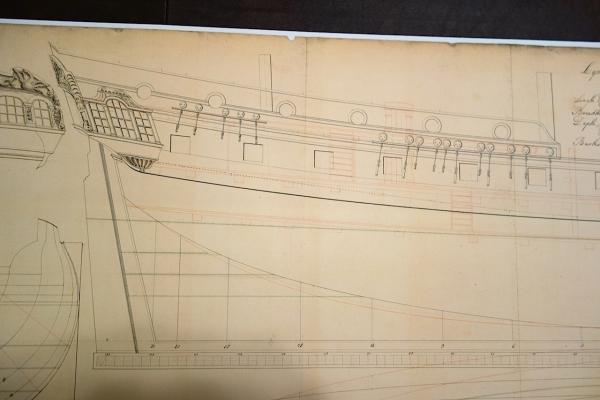
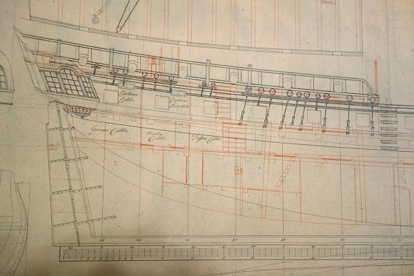
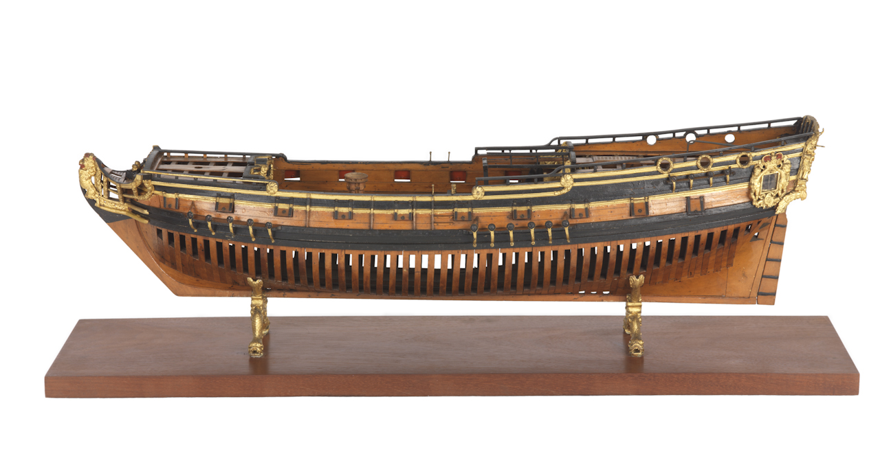
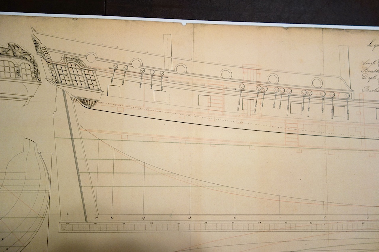
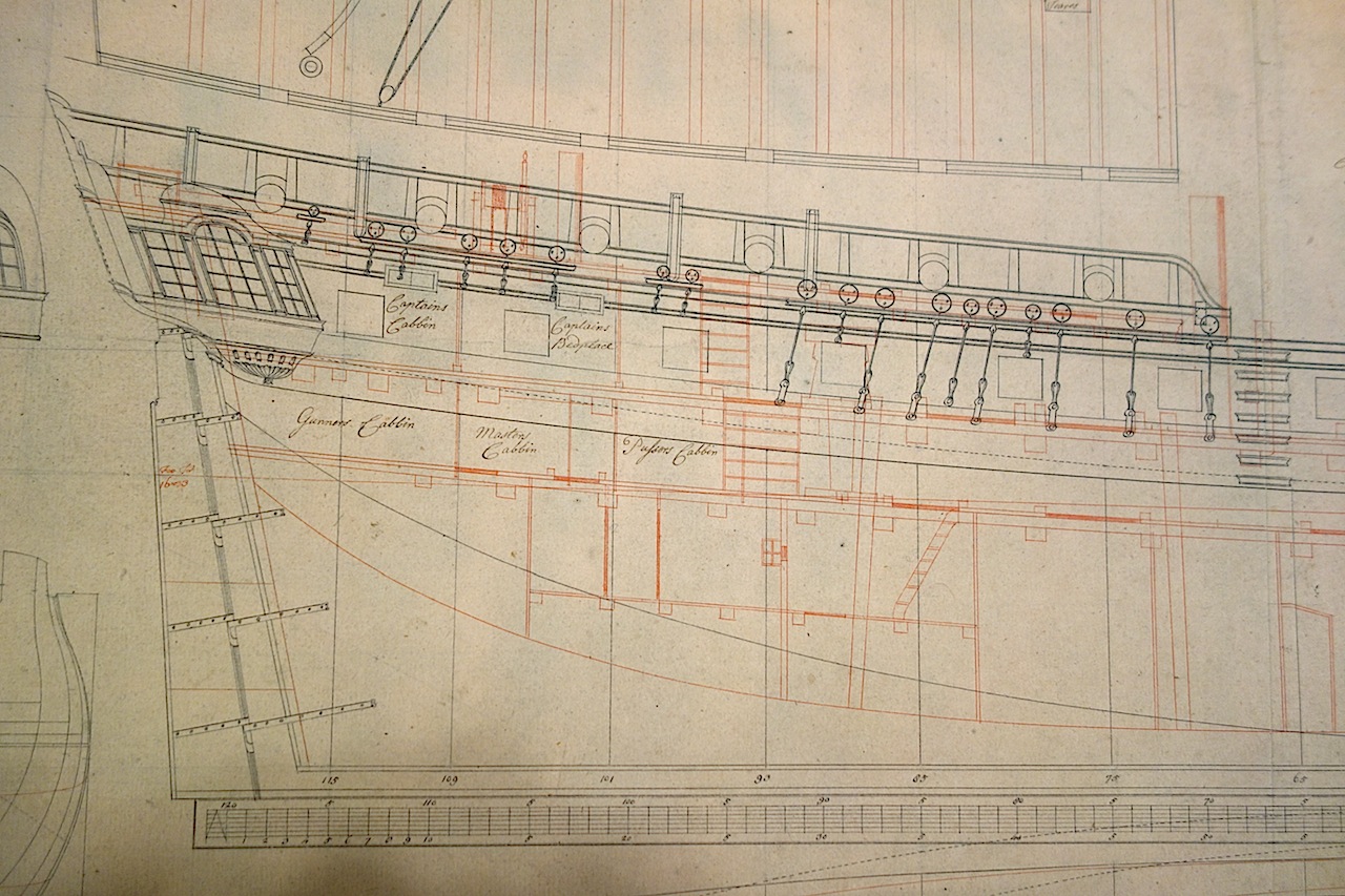
John, thanks for the very kind words. The Chapman plans may seem a little confusing and wrong, but I have a feeling he might have been accurate. His other drawings are very complete, showing railings (see the ship above the Unicorn) where there were railings. It makes me think that there may not have been any railings on the Unicorn, as Chapman likely would have added them. I think what you see is a solid bulwark extending all the way. The bulwarks are fairly high up at the fore end of the quarterdeck, and maybe there less of a need for railings. I took another look at Gardiner's "The Sailing Frigate" -- in Chapter 4 on "The 'True Frigate' 1748-1778", it sounds like the Unicorn might not have had a quarterdeck railing as it was substantially designed off of French lines at the time: "...French designers had achieved an important advance by a subtle alteration in the layout of 'two-decked' cruisers. British 24s had a heavily framed full height lower deck, necessary to fight the guns and to allow rowing with standing oarsmen . . . . By contrast, in the latest French ships the lower deck was little more than a light platform, with much reduced headroom, and the deck itself, at its lowest point, positioned just below the waterline. This compressed the height of the topside, while the forecastle and quarterdeck were unarmed and had virtually no barricades or rails to catch the wind; combined with fine lines and light framing, this made for fast and weatherly ships. . . . This formula was eventually adopted by all the major navies, and was dubbed the 'true frigate' form, in retrospect, by naval historians." (emphasis added) For the Lyme plans, I think what you see are the portholes mostly existing in the open area between the top of the solid bulwarks and top of the rails. They are almost the reverse of the Unicorn, where the porthole outer circumference opens up at the bottom, whereas the Unicorn's open at the top. The portholes were probably somewhat decorative, and were framed on either side. Here are a few ships shown in the Gardiner book from the NMM that I think exemplify what the Lyme's quarterdeck portholes might have looked like: I think I am going to go with the Lyme. The plans I have are very detailed, though I think I could use them without issue for the Unicorn. The differences as I can tell are (1) the Unicorn was a beakhead ship, (2) the Unicorn had a Unicorn figurehead while the Lyme had a lion figurehead, (3) the Unicorn's railings were a little more decorative at the ends with the curls versus more straight ends for the Lyme, (4) the Unicorn has an extra railing at the stem which seems a bit different from other ships, and (5) the rudders and shape of the lower stem are a bit different. For me, it just boils down to the fact that I like the looks of the Lyme a little more than the Unicorn the way the windows are sized and shaped, and the stern decorations. Unfortunately what I can't tell from Chapman is whether the cathedral windows were full windows, or were square windows with decorative arches at the top. The Lyme's middle window on the stern galleries is a full cathedral style window, so maybe the Unicorn actually had those windows throughout the stern?


-
Beautiful work Mobbsie. It's coming along very nicely
- 1,279 replies
-
- 1
-
-
- agamemnon
- caldercraft
- (and 1 more)
-
Thanks Ian. I was wondering about that as the bar does go to 120, which happened to match the length of the ship.
-
Yes, I'm not sure what Corel was modeling this ship off of. I'm just impressed that Ian made the call that the tiller had to be on the quarterdeck without the benefit of all these high resolution plans! The plans are probably close to three feet in width. I'm not sure of the scale unfortunately - that will make transferring dimensions to the Corel 1:75 scale a bit tricky until the scale is determined.
-
I am confused half the time with some of the lingo as well. There was a long time where I was interchanging bulwarks and bulkheads. Even worse, I just realized I have been misspelling "bowsprit" the last five years What I love about this hobby is not only the craftsmanship/building aspect, but also the learning aspect - history, technology, mechanics, etc. Your Bounty is very nice! I should probably take my own advice, but don't get overwhelmed by all you have to do - just break things up into small discrete tasks. The decision on the sails is yours alone - do you want to build a model with sails? If so, where there is a will there is a way You'll have to spend some time researching - I probably spent two months of reading and planning things out. But, I wasn't in a rush to finish the model as I got more out of the journey than the destination. In the end, I think everyone wants a model they can be proud of, so if you like ships with sails, add sails! I may be overstating, but standing rigging is fixed. It includes all the various stays to keep the masts in place and the shrouds (which are probably a form of stay). Running rigging is a working line - the lines enable one to raise and lower sails, move the spars, hoist or lower things, etc. Do you have the Lennarth Petersson book "Rigging Period Ship Models"? If you're like me and learn more from pictures than words, it is an invaluable resource to learn all the rigging that goes into a ship. The book is entirely composed of pictures, and no words. It is fantastic.
-
Mike, the Badger was my first ship. If I can do it, you can do it You don't need all the running rigging if you use furled sails. I did the clew lines, buntlines and sheets. The leech lines would be hidden I think, so I didn't bother with those. There may be another set of lines that I also didn't add. The clew lines, buntlines and sheets should be in your kit plans for the masts. The bowsprit takes a little more work with the jib sails, as you need to add jib stays and halliards. You also need chocks, a jib traveler, suitable belaying points. Take a look here - this might help: http://sailing-ships.oktett.net/square-rigging.html Good resources are Lees "Masting and Rigging" and the TFFM volume 4. I recently bought Marquardt's "Eighteenth Century" book which also looks pretty good. Hope that helps.
-
Landlubber Mike's technique for furled sails
Landlubber Mike replied to Landlubber Mike's topic in Masting, rigging and sails
Ian B, I hope it helps. I had searched but really couldn't find too many in-depth sail tutorials, so I thought I would share my approach. I think sails, furled or not, add a very nice look to the model and are well worth the extra time. I'm probably going to go with a mix of furled and unfurled sails on my next builds, as you are thinking - just be aware that if you are using full sails, there are a number of other lines that may need to be installed. If you come up with new techniques, feel free to share them on this thread - I'm always looking to improve my work. Good luck! -
Hi again John. I just posted some pictures of the NMM Lyme plans on my Unicorn log. I thought you might find these two pictures helpful, as they show the quarterdeck railing.