DONATION DRIVE - SUPPORT MSW - DO YOUR PART TO KEEP THIS GREAT FORUM GOING!
×


Landlubber Mike
-
Posts
4,541 -
Joined
-
Last visited
Content Type
Profiles
Forums
Gallery
Events
Everything posted by Landlubber Mike
-

Landlubber Mike's technique for furled sails
Landlubber Mike replied to Landlubber Mike's topic in Masting, rigging and sails
Sjors, for the fore topsail and jibsail, I installed the sail (cut to a much smaller dimension) to the related line and then furled the sails by pulling them down the line and adding the creases, etc. -
Thanks guys. Spyglass, I remember you pointing out the bitts issue. Mine is bigger than the plans also Martin, I bet I end up cutting out new bitts out of pear or redheart. If I'm replacing most of the other visible wood, I might as well go all the way and replace all the ply and walnut where visible
-
Thanks for these thoughts Spyglass. Just out of curiosity, I saw that some of the holes around the main mast match up with holes just below on the lower deck. I forget if these are for the bitts or whatnot, but are there pieces that need to extend through the holes on the upper deck down into the holes on the lower deck?
-
Thanks Chuck, that makes sense. I haven't tried spiling yet, but that's good to keep in mind about having wider planks to work with.
-
Thanks Martin - it sounds like reinforcing the upper deck makes a lot of sense. It shouldn't be too hard to cut out two or three pieces of plywood to fully close off some of the bulkheads in the middle. The big concern is to make sure you get the camber of the deck right, but I think I can figure that out. Even if I'm off by 1 or 2mm, it probably won't make much of a visible difference once the planking and deck items are on. I'm probably not going to add blocks between the bulkheads on this build. I did so on my Lyme build (see link below), as the bulkheads in that kit are plywood and have a lot of flex. The Pegasus kit uses MDF which is incredibly strong and really can't be flexed at all. http://modelshipworld.com/index.php/topic/6223-hms-lyme-1748-1760-by-landlubber-mike-kit-bash-of-corel-unicorn-scale-175/?p=220346 It might be hard to get close-ups of the extensions with the bulkheads on the model, but I can try tonight. Here are some that I posted on my log earlier (prior to sanding and finishing them). http://modelshipworld.com/index.php/topic/7267-hms-pegasus-by-landlubber-mike-amativictory-models-scale-164/?p=238373
-
Thanks for the warning Spyglass. I am planning to make the adjustments where the templates meet the bulkheads, rather than the middle. The two-piece upper deck templates are fairly flimsy as you say. Looking at the set up now, I wonder why the middle bulkheads weren't built as full supports across the full deck. I might think about adding some supports at the middle, but I worry that I might affect the camber of the deck. I'll have to think about that a little more. When I planked the deck on my Badger, I used long thin pins along the length of the plank to keep the plank straight and butt hard against the plank next to it when gluing it down. It worked very well on that build, but I wonder if that approach might end up collapsing the deck at the center. Interestingly, the kit instructions call for you to plank the first third and the last third of the upper deck, and then leave the middle part for later. That would leave an odd planking run, which maybe is mostly covered up by all the deck items, but I still think it would look odd. I could be wrong, but I think the instructions also say to plank the templates off the model. I think it would be hard to fit the planked templates and bend them to conform to the deck camber. So, I'm planning on adding the templates, and then planking the deck in full.
-
Thanks Alistair. I was wondering about whether to plank the lower deck under that hatch. You probably can't see much with the stairs in the way, but it probably wouldn't hurt to add a few strips down there.
-
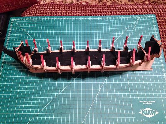
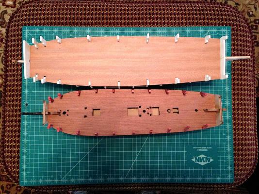
Some more steady progress. I ended up adding the bulkhead extension supports using spare plywood - I figured the extensions may experience some significant lateral forces during the fairing of the bulkheads, so hopefully the plywood supports on either side keep the extensions in place. I also ended up using the GF "black" stain to darken the lower deck and other parts of the keel. I'm not sure if that was necessary, but I thought it might help ensure that the light MDF color from the keel and bulkheads didn't pop out when looking under the quarterdeck and forecastle. Next up is to glue on the upper deck. I need to modify the pieces slightly as the two halves of the template overlap by 1-2 mm. I'm also going to start pinning the gunport templates, as I think it might take a few sessions to get the ply templates to fit the way they should.
-
Thanks Brian. I've cut some pieces for the keel of my Lyme build on the saw, but I need a lot more practice. That thing scares the crap out of me, especially having some kickback when I first started using it (which went away after I pushed out the back end of the fence a tad). I bought one of these with the 1/8" leg attachment to see if it makes things a little safer and easier. I'll post my experience with it after some trial runs. http://www.microjig.com/products/grr-ripper/index.shtml
-
Brian, I have a Byrnes saw John, thanks very much. I sorta figured that things would be case dependent.
-
Hi everyone, This might seem like a silly question, but I was wondering how people approach cutting planks from wood sheets. I ordered a bunch of sheets from Jeff at Hobbymill, which are 3" wide and I think 18-24" long. When cutting planks from those sheets, is it better to cross cut the sheet to the length of the planks I will need, and then cut the individual planks from that piece? Or should I cut planking strips from the full sheet, and then cut them individually to size? I can see the benefits of both approaches, but wasn't sure which would be the most efficient use of the wood. Thanks in advance!
-
Really nice work Nils. Your build is definitely an inspiration for my Pegasus as I go forward with my build. I agree about the rigging too. With my Badger, someone told me after building the hull that I was 2/3 of the way done. I almost felt like the rigging was equal to, or more than, the hull work -- though I did add sails to my build. It probably would have been shorter had I not in my clumsiness been constantly bumping into the spars and busting off blocks and lines
-
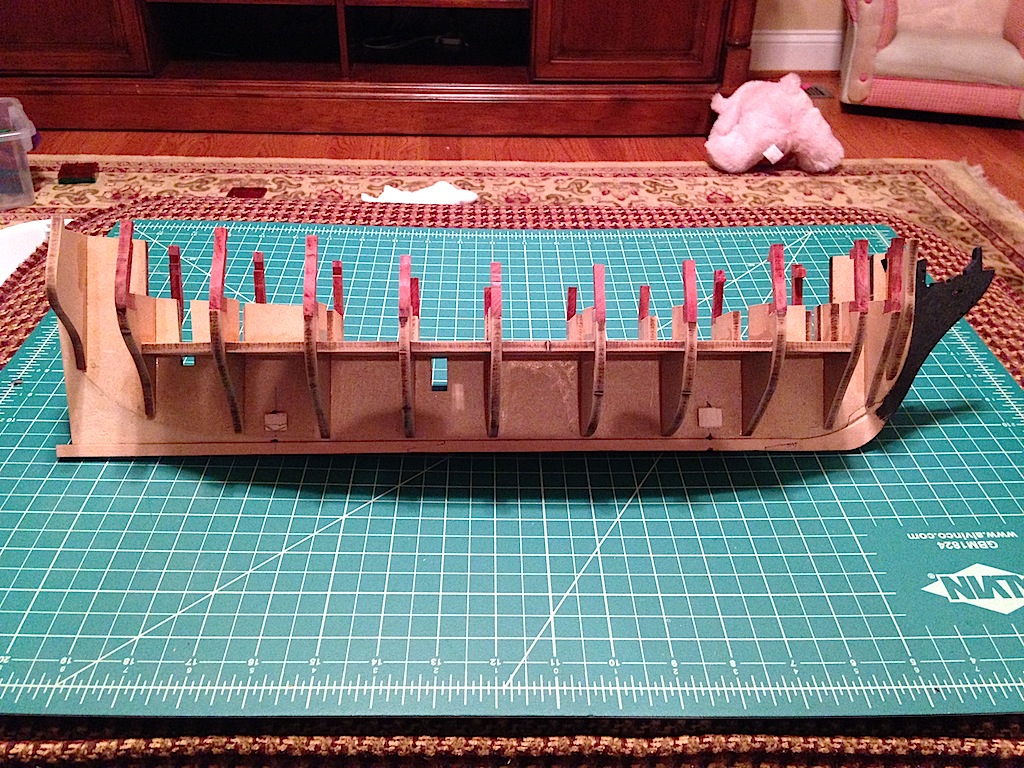
Thanks Martin - I had a similar thought about the bear, but wanted to keep my thread family rated Thanks Ian. The Unicorn is a bit longer, taller and wider even at the smaller scale as you can see in the pictures below. I should have added the stem to the Unicorn (which as you know is a beakhead ship so it probably looks a little shorter at its front at the moment), and the Pegasus will extend a little further back by an inch or two after the stern extensions are added. I dry fitted the upper decks to get a sense as to the height differential. Interestingly, I thought the Pegasus was going to be a lot smaller when I first started on the build, but it seemed to get a lot bigger once the bulkheads and stem were attached.
-
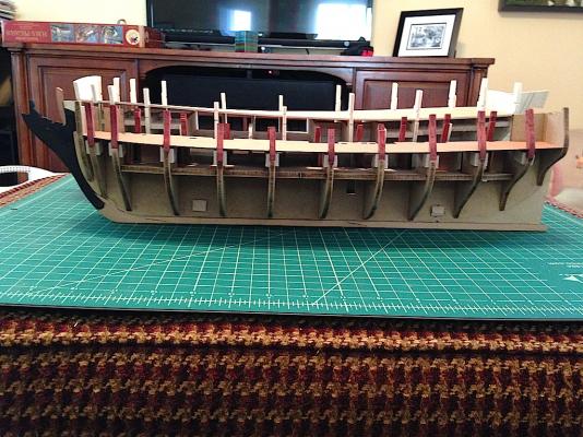
Exciting development - I now have the skeleton of the hull. And yes, that is one of my daughter's pink teddy bears in the background (too lazy to move it for the picture) I think I mentioned this before, but in terms of its "bones," this kit is very impressive. The MDF for the keel, bulkheads and lower deck is flat and very strong. Even more impressive is the fact that the fitting of the bulkheads and lower deck to the keel couldn't have been more perfect, as everything fit together like a glove. I probably didn't need to glue the assembly together it fit so well, but I did end up gluing the bulkheads and lower deck onto the keel, and then added glue into all the seams between those pieces. Other kit manufacturers could probably learn a good lesson from this kit. After dealing with all the issues on the Corel Unicorn kit, I almost felt like I was cheating in only having to cut out the pieces and stick them together without needing to check for flatness, symmetry and conformity to the plans, fit, etc. Oh, and Jeff's redheart was milled to a perfect 5mm in width. Despite the very snug fit between the 5mm bulkheads and the lower deck, the lower deck slipped over the new extensions without any issues at all. Thanks Jeff! Next up I'm planning to add plywood blocks over the bottoms of the redheart extensions to help secure the joints. I think the instructions call for one to add the upper deck template as well, so I'll be working on that. I also need to take a look at the NMM plans to see if there are any modifications to the kit that I would like to make regarding the deck layout (like converting hatches to stairways).

-
Hey guys, thanks for chiming in. It's funny, after I wrote my post, I was thinking that maybe I should have let the grain run vertically on the extensions. Really, only four of the extensions will be fully visible (the ones at the rear of the forecastle and the ones at the front of the quarterdeck). The others will still show the red color, but with limited visibility as they will be under the decks. I'm not too concerned about the integrity of the material for these pieces, as really there will be no work done on them on the visible side - but definitely, point taken as I create other pieces, thank you! Ian, I agree on keeping all the same colors. I was thinking that I might be able to use stains on different woods, but each wood comes out a slightly different color with the same stain (with the exception of black). So, I was stuck using the same wood for all the pieces. I thought I could substitute walnut on some of the pieces, but in my kit, the walnut is in a variety of shades. That meant that I could have used pear and stained it, or I could just use redheart. The nice thing about Jeff's wood is that he matches the wood in your order, so you don't end up with various shades like I found in my kit. Martin, I picked up the GF "Cranberry Red" over the weekend. I might test that out on pear for my Lyme build, though I've really liked working with, and the color/grain of, the redheart. Jeff mentioned that when redheart is exposed to sunlight, it turns an orangish color. So he recommended a sealant with a UV protectant. The guys at Woodcraft told me that those sealants break down over time anyway, so all you end up doing is delaying the inevitable. Since I'm not expecting the expose the model to direct sunlight, I'm not too worried. But, I thought that I'd pass that along.
-
Thanks for all the support. I wonder how all this "painting with wood" is going to work out in the end, but I'm a fairly stubborn person that likes a challenge, so I think I'm going to see this through to the end . . . . I've made a little more progress this week. I finished the bulkhead extensions, and did the quarterdeck and forecastle deck beams as well. I'm sure most of these items won't be visible once the two decks are added, but I figured I would go ahead and practice creating the parts, to give me a little bit of extra experience before cutting the important pieces which will be visible at bulkheads 4 and 8 (essentially, the rear of the forecastle and front of the quarterdeck, respectively). They will need some very light touch-up sanding, but otherwise they are in pretty good shape I think. The whole process wasn't too bad actually - Jeff's redheart is a pleasure to work with. I think I'm going to use redheart on my Lyme build as well. It will be a little tricky given that the bulkheads are already glued to the keel on that model, but I think I should be able to manage. One interesting thing was thinking about how I wanted the grain to run on these pieces. I didn't pay much attention to that when doing the first three extensions at the waist that will be ultimately removed anyway. But, I thought that if the grain of the bulwark planking ran from stem to stern, then it might look a little odd if the grain on the extensions ran perpendicularly. So, I went ahead and made the extensions and the deck support beams all run horizontally. In the end, it probably doesn't matter all that much, but it's probably typical of the things we obsess with in this hobby. You'll see that I also added small blocks to lock the bolts for the pedestals. I needed to cut a groove into the blocks as the nuts were a bit wider than the 5mm keel, but I think the nuts are now fully locked in. I also had to taper the rear blocks given the narrowing of the keel at that area. The exciting part now is that I will be able to glue the bulkheads into the keel, and start work on planking the deck and hull. A slight detour in replacing the bulkhead extensions, but slowly but surely things are moving along.
-
Thanks Martin. It sounds like it might make sense for me to start playing with the gunport strips before gluing down the bulkheads, just to make sure that they are sitting on the keel correctly.
-
Hi Martin, glad you got that resolved. How did you figure out that bulkheads 1 and 12 were sitting too high? I've been test fitting my bulkheads, and they seem to fit perfectly, though the first couple do require a bit of pressure to get fully seated down onto the keel. By the way, in catching up on your log I read your post about using Cranberry Red for the gun carriages. It looks really nice - I was wondering what Cranberry Red looked like. I ended up deciding to go with using Redheart for the frames, bulwark planking, carriages, etc., but staining is another very good option.
- 467 replies
-
- 1
-

-
- fly
- victory models
- (and 1 more)
-
Hi Ian, the hooks and tackle look great. For the height of the bulwark rings, maybe take a look at zu Mondfeld? If you don't have a copy of the book, you can get a preview at the following link on Google (I typed in "zu Mondfeld cannons" into the search field). It looks like your height is in the ballpark, but your picture is at a slight angle to really tell relative to zu Mondfeld. http://books.google.com/books?id=5nrXLkfLBGcC&pg=PA167&lpg=PA167&dq=zu+mondfeld+cannon&source=bl&ots=HdLqdMjksX&sig=CYhhB9IWuU-FqUDZcclLBXLCang&hl=en&sa=X&ei=khYXVOKCFK61sQSZ24GgCA&ved=0CDgQ6AEwAw#v=onepage&q=zu%20mondfeld%20cannon&f=false Hope that helps!
-
Looks great Joe, you're moving along quickly. Cannons look fantastic!
- 302 replies
-
- 1
-
-
- granado
- caldercraft
- (and 1 more)
-
Really nice work Jason. What a pain about the third bulkhead. Is it necessary? It seems that is where the hull curves in towards the stem, so maybe it is critical at that spot. Could you maybe remove it after you have the first/second layers of the outside hull planking on (sorta like the other extensions that typically are removed from the bulwarks once the exterior hull planking is on the ship)? I really like the look of the maple. The tanganyika in my Badger kit was prone to splintering and a number of the pieces were warped, but I had just enough good pieces to finish the deck. I'm switching to maple for my Pegasus though - it looks like a very nice wood.
-
Thanks very much guys! Ian, I considered using the pin method, but I think adding the plywood blocks on either side should hold everything together better. I found on my Badger that some of the pinned parts that required a lot of handling (like the spars), ended up loosening over time. To answer your question though, I think properly done, the pin method could work well. Alistair, some might say passionate, most would probably say masochistic I think you're right about the bulkhead extensions in the waist area, argh! I could have sworn that I saw some models with those extensions intact, but in looking at the instructions again, it appears that I was mistaken. Of course, those were the three bulkheads that I started with last night (as they were easier). I think at the upper deck level, only the extensions serving as supports for the quarterdeck and forecastle deck should remain. Oh well, I got a little practice in at least before doing the harder ones. The other mistake I made is in adding the plywood supports now before the bulkheads were secured to the keel. There is a 5mm thick frame that supports the upper deck that has to be inserted down on top of the bulkheads. Easy fix in that all I need to do is sand the plywood off, but another consequence of not thinking ahead
-
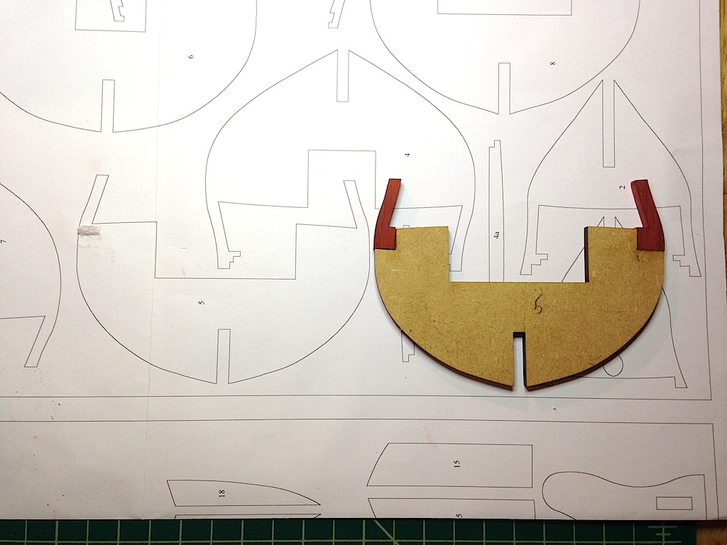
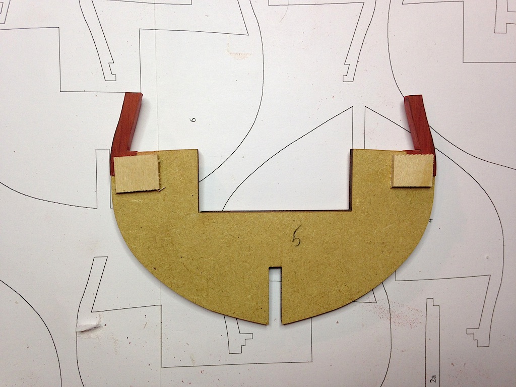
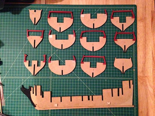
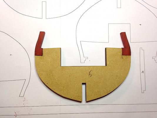
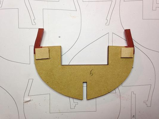
I'm back in the shipyard after a little hiatus - had an out of town vacation/family visit (where I got to slip in a quick trip to Mystic Seaport to see the Charles Morgan), and then needed some time to recover from my family Last I left off, I was trying to figure out the bulwark frame extensions and how to "paint them with wood." After a lot of thought, I came up with two possible approaches. The first was to create new bulkhead extensions out of the new wood, and glue them in place. The second was to create new extensions, but rather than replace the original extensions, I would cut a slot into the new extensions, thin down the original extensions, and then slide the new extension over the original like a sleeve. The second seemed to add a bit of work, and I wondered about the structural integrity of having the original extension thinned down, so I went with the first option. Using my scroll saw, I cut out the original extensions along with a piece from the body of the bulkhead, and used that piece to mark out the replacement extension on the new wood. After gluing on the new extensions, I went ahead and glued pieces of 3mm plywood on either side of the new wood. I figured that will give the new extensions added strength, as I worried that the sanding of the bulkheads and the planking could stress the glue joint. It seems pretty locked in now. I'll need to do a little touch up sanding, but otherwise, that's all that there was to the process. It takes a while, but I managed to knock out three bulkheads tonight. Hopefully this works out. The replacement wood that I'm using is Redheart from Jeff at Hobbymill - it's a really easy wood to work with, and reminds me a lot of Jeff's pear. The wood is very tightly grained and machines well, but does have dark streaks going through it. The streaks don't bother me, and I actually really like the look of it as a replacement for painting the bulwarks red ochre. I think after it is oiled or otherwise finished, it will give off a more textured look than if I had painted it - exactly why I'm trying to avoid paint in the first place. Unfortunately, this means I'll have to scratch the gun carriages as well.

-
Very nice work Ian. It's very hard to get the cannon blocks to be in proper scale, particularly with the hooks I've found at this scale. I think the shanks could be shortened a bit, but your cannon rigging is looking fantastic.