Landlubber Mike
-
Posts
4,547 -
Joined
-
Last visited
Content Type
Profiles
Forums
Gallery
Events
Everything posted by Landlubber Mike
-
 Hi Ian, the hooks and tackle look great. For the height of the bulwark rings, maybe take a look at zu Mondfeld? If you don't have a copy of the book, you can get a preview at the following link on Google (I typed in "zu Mondfeld cannons" into the search field). It looks like your height is in the ballpark, but your picture is at a slight angle to really tell relative to zu Mondfeld. http://books.google.com/books?id=5nrXLkfLBGcC&pg=PA167&lpg=PA167&dq=zu+mondfeld+cannon&source=bl&ots=HdLqdMjksX&sig=CYhhB9IWuU-FqUDZcclLBXLCang&hl=en&sa=X&ei=khYXVOKCFK61sQSZ24GgCA&ved=0CDgQ6AEwAw#v=onepage&q=zu%20mondfeld%20cannon&f=false Hope that helps!
 -
Looks great Joe, you're moving along quickly. Cannons look fantastic!
- 302 replies
-
- 1
-

-
- granado
- caldercraft
- (and 1 more)
-
Really nice work Jason. What a pain about the third bulkhead. Is it necessary? It seems that is where the hull curves in towards the stem, so maybe it is critical at that spot. Could you maybe remove it after you have the first/second layers of the outside hull planking on (sorta like the other extensions that typically are removed from the bulwarks once the exterior hull planking is on the ship)? I really like the look of the maple. The tanganyika in my Badger kit was prone to splintering and a number of the pieces were warped, but I had just enough good pieces to finish the deck. I'm switching to maple for my Pegasus though - it looks like a very nice wood.
-
Thanks very much guys! Ian, I considered using the pin method, but I think adding the plywood blocks on either side should hold everything together better. I found on my Badger that some of the pinned parts that required a lot of handling (like the spars), ended up loosening over time. To answer your question though, I think properly done, the pin method could work well. Alistair, some might say passionate, most would probably say masochistic I think you're right about the bulkhead extensions in the waist area, argh! I could have sworn that I saw some models with those extensions intact, but in looking at the instructions again, it appears that I was mistaken. Of course, those were the three bulkheads that I started with last night (as they were easier). I think at the upper deck level, only the extensions serving as supports for the quarterdeck and forecastle deck should remain. Oh well, I got a little practice in at least before doing the harder ones. The other mistake I made is in adding the plywood supports now before the bulkheads were secured to the keel. There is a 5mm thick frame that supports the upper deck that has to be inserted down on top of the bulkheads. Easy fix in that all I need to do is sand the plywood off, but another consequence of not thinking ahead
-
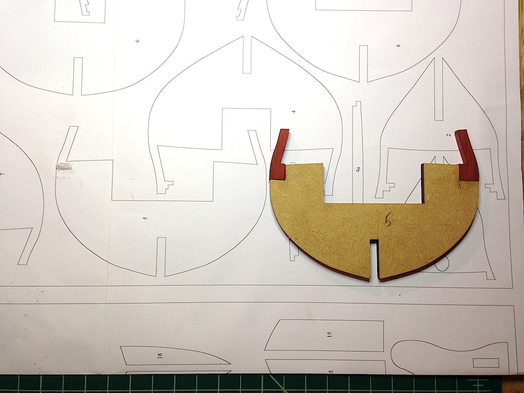
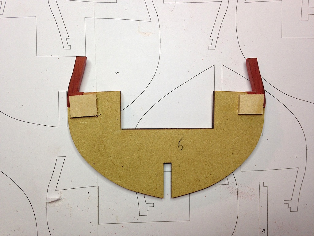
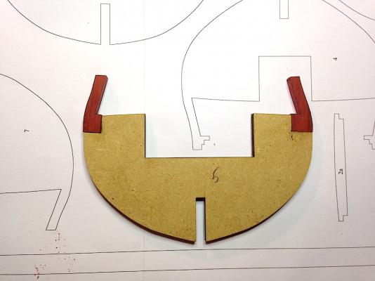
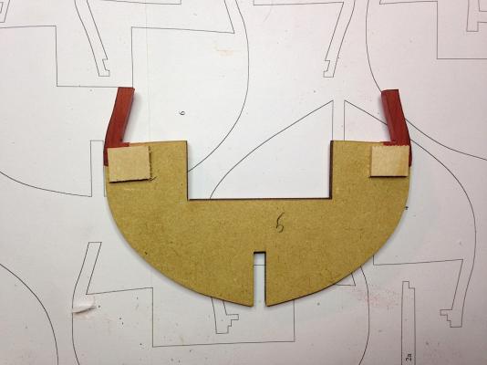
I'm back in the shipyard after a little hiatus - had an out of town vacation/family visit (where I got to slip in a quick trip to Mystic Seaport to see the Charles Morgan), and then needed some time to recover from my family Last I left off, I was trying to figure out the bulwark frame extensions and how to "paint them with wood." After a lot of thought, I came up with two possible approaches. The first was to create new bulkhead extensions out of the new wood, and glue them in place. The second was to create new extensions, but rather than replace the original extensions, I would cut a slot into the new extensions, thin down the original extensions, and then slide the new extension over the original like a sleeve. The second seemed to add a bit of work, and I wondered about the structural integrity of having the original extension thinned down, so I went with the first option. Using my scroll saw, I cut out the original extensions along with a piece from the body of the bulkhead, and used that piece to mark out the replacement extension on the new wood. After gluing on the new extensions, I went ahead and glued pieces of 3mm plywood on either side of the new wood. I figured that will give the new extensions added strength, as I worried that the sanding of the bulkheads and the planking could stress the glue joint. It seems pretty locked in now. I'll need to do a little touch up sanding, but otherwise, that's all that there was to the process. It takes a while, but I managed to knock out three bulkheads tonight. Hopefully this works out. The replacement wood that I'm using is Redheart from Jeff at Hobbymill - it's a really easy wood to work with, and reminds me a lot of Jeff's pear. The wood is very tightly grained and machines well, but does have dark streaks going through it. The streaks don't bother me, and I actually really like the look of it as a replacement for painting the bulwarks red ochre. I think after it is oiled or otherwise finished, it will give off a more textured look than if I had painted it - exactly why I'm trying to avoid paint in the first place. Unfortunately, this means I'll have to scratch the gun carriages as well.

-
Very nice work Ian. It's very hard to get the cannon blocks to be in proper scale, particularly with the hooks I've found at this scale. I think the shanks could be shortened a bit, but your cannon rigging is looking fantastic.
-
Very nice work Ian - you have a lot of creative ways to come up with jigs and templates. I'm going to have to file your caps jig for future reference, it is perfect!
-
Very nice work Joe. I really like the Polly Scale Aged White - I wish I had seen that paint color before using the Admiralty Paints "Dull White" on my Badger. Sorry about your cannon dilemma. Hope it gets resolved soon.
- 302 replies
-
- 1
-
-
- granado
- caldercraft
- (and 1 more)
-
Your Unicorn is working out very nicely Ian. Excellent job! I really like the last picture - the model looks fantastic!
-
Thanks for the picture BE, that's very helpful to see them all side by side.
-
Thanks Spyglass - I'll add some blocks which should help. Thanks for the tip on the threads. I did do that when setting the nuts, and they turn freely thankfully. I'm also planning on adding the stern post after the second planking. For the stem, using long planking pieces I thought it would be easier to start by setting the planks into the rabbet, then work them around the hull, and filing off the excess after the second planking. It didn't seem necessary to have the planks extend and get filed back at the stem as well if you have a rabbet, but I'll find out soon whether that was a good idea
-
I thought about doing it that way for that reason as well, and if I remember correctly, Bob Hunt's practicum recommends installing the stem after the first planking is installed. It didn't seem to make much difference to me if I installed the stem before the second planking or before the first, so I just went with installing it now. Plus, I wanted to get the keel pieces attached to fix the nuts in the main keel, and it just seemed more logical to add the stem so that the keel pieces were positioned correctly. I'm hoping the rabbet helps make for a clean joint between the planking and the stem, but we'll see. On my Badger I had a heck of a time with the planking at the stem, but I hadn't cut a rabbet nor had I pre-shaped the planks. This time I plan to pre-shape the planks which should help.
-
Thanks guys. I didn't sand the char fully through, but it seemed to have been fine just taking off most of it. Spyglass, that's an interesting approach on installing the stem later in the build. I'll have to think about that one for my next one. On the holding blocks, my nuts are wider than the 5mm keel, so if I added blocks on either side I would likely have to carve a groove into them. The nuts are really epoxied in - I first added epoxy to the side and bottom of the nuts, and then once they were glued in tight, I added epoxy along the exterior to further seal them in. I'm using the same stuff (Gorilla Glue 5 min epoxy) on some gardening equipment, and despite all the abuse, the epoxied parts are not going anywhere. That being said, rather than putting blocks on the sides of the nut, I was thinking about small blocks of wood above the nut inside the slot on either side of the screw path. That would help restrain the nuts from popping up, which I think is more likely than the nuts popping from side to side.
-
Quick question - the kit uses laser cut parts. I've seen some logs where the builder sands off the charred areas for the purpose of ensuring a stronger glue bond. Is that necessary? I sanded off the char on the pieces I glue to the keel thus far, but maybe I should have tested gluing them without sanding. Interesting thing is that it smells like burning wood as you sand off the char.
-
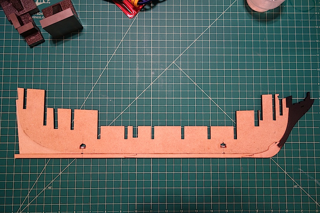
Small update on where I am now, which mostly involved preparation of the main keel. I carved the rabbet and sanded the bearding line. The MDF is interesting to work with - it was very easy to chisel the rabbet and bearding line, as the layers just flake off with little effort. Sanding on the other hand seems much more difficult than if you were to sand plywood. That should make fairing the bulkheads a real pain - I'll probably start with a sanding block, but I have a feeling that I will end up resorting to the Dremel or other power sanding tools. I also epoxied nuts into the hull for the pedestals. I'm using two-inch #6 machine screws, which seem to work very nicely with the brass pedestals I bought from Model Expo. Installing the nuts was actually easier than I expected. The only issue that I ran into is that I goofed in installing them before I added the keel pieces. It would have been a lot easier to drill the hole in one shot, but instead, I had to guess where the line was, and then ream the hole a little larger so that the screw had a clear path to the nut. All in all, it wasn't that difficult though. You'll see that I installed the stem and keel pieces at this time. I went back and forth on whether to install them now or wait until after the first or second planking, but I thought that fitting them at this stage would make it much easier to ensure that the pieces were perfectly centered on the main keel. I also decided to go with a black stem on this build, and used the General Finishes black stain that I tested earlier. I was am happy with how it looks - a deep black, yet it doesn't have the "plastic-y" feel of a painted surface. It also is easier to apply than paint, where I just used a piece of an old t-shirt to apply the stain and then wipe off the excess. I did two coats, but I probably could have gotten away with one. It's probably hard to see in the picture, but I have to add some shim pieces to the keel at the two connecting joints. The pieces fit nicely together, but there was a slight gap. I thought it would be a stronger bond to clamp the pieces at the joints, but now there is a very slight dip along the bottom of the keel at the joint. So, I'll glue a small piece at the joint and sand the keel to a straight line. I'm still debating the timing and general approach to replacing the visible bulkhead extensions with other wood. I'm itching to glue the buikheads to the keel now, but it probably is easier to take care of replacing the extensions now, while the bulkheads are off the model.

-
Really amazing work Bob. Kudos to you for sticking with this kit through the various issues. I noticed that ME's latest catalog didn't include the Essex - hopefully they have worked out all the kinks.
-
Very nice Joe. It sounds like it was a good decision to wait for Jeff's wood as opposed to working with the kit supplied strips. I haven't worked with his boxwood yet, but his pear has been a perfect wood to work with.
-
Thanks for sharing Martin. I'm curious what you think about the RB guns versus Chuck's guns. I think BE and Alistair concluded that the RB guns are probably perfect to scale, but it looked to me like Chuck's guns would be fine as well. Since you used the heartwood for the capstan, are you thinking about building the gun carriages out of heartwood as well? I was hoping to avoid that, but if I'm going to use redheart for the bulwark planking, I don't know if I can stain the gun carriages to match the redheart and don't want different shades of red on my build.
- 467 replies
-
- 1
-
-
- fly
- victory models
- (and 1 more)
-
Thanks very much my friends, I really appreciate the kind words. This hobby is amazing, but equally amazing is the meeting of many nice friends all over the world. I feel very fortunate to have stumbled into the world of ship modeling
-
Very nice work Martin. I like the use of the specialty wood - it gives a nice red color
- 467 replies
-
- 1
-
-
- fly
- victory models
- (and 1 more)
-
The golden mean sounds like a good one. I'm trying to use as much of the kit as possible too, but it seems like I find more stuff to replace. I just placed an order with Jeff at Hobbymill for the Pegasus and for some supplemental wood for my Unicorn, and the cost does add up (thankfully, I've paid significantly below retail for these kits). I think once I finish the kits on my shelf, I'm going to move towards buying good plans and go into scratch building. My Unicorn is almost looking like a complete scratch build outside of using the kit bulkheads
-
Hi Martin, I believe that I bought the General Finishes stains from Woodcraft (online). They have lots of different shades, as you can see here: http://generalfinishes.com/retail-wood-finishing-products My best success for the black was using the "stain", rather than the "dye stain." Maybe I needed to stir the dye stain a little more. They have some interesting colors for ship building. For example, they have a yellow that seems like it could work nicely as a yellow ochre replacement. The great thing about using stains is that you don't get that painted on texture. Some people thin down paints and paint 20-30 coats, but I'd rather put on one or two coats of stain and be done. I'm not sure what I want to do with the bulkheads yet. The downside of stains is that you don't get an even color across different wood types. I'm thinking of removing the bulkhead extensions, and replacing them with stained wood of the same type that I will use for my bulwark planking and cannon carriages. Still thinking about whether to do that before the hull planking, or after it.
-
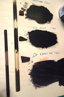
In my quest to avoid using paint, I spent a little time experimenting with some black stains and dye stains that I had samples of - Varathane 'Ebony', General Finishes 'Black" stain, and General Finishes 'Ebony' dye stain. I also have a small amount of Fieblings Leather dye, though we all know that works well to dye pear so I didn't test it. It's always hard to accurately get the full effect of color on a digital picture, but here is a picture of the test - the big board is plywood, the small pieces are scrap pear, the longer dowel is from the Corel Unicorn kit (I think beech) and the smaller dowel is from the Pegasus kit (ramin). I didn't bother to test the Varathane on the smaller dowel as it didnt have as much penetration as you can see. The results of just trying one coat are interesting. The GF black stain worked the best - very deep black that looked like the wood had been painted. The Varathane and the GF dye stain were more like your typical stain effect, where it mostly highlighted the grain. I would have thought that the GF dye stain would be the best, as GF markets the dye stains as having deeper penetration. Maybe I needed to mix it more, I'm not sure. I really like the GF black stain - you end up with a deep painted look, yet the wood texture is not hidden under a layer of paint. Just the look I'm after. In any event, I thought I would share in case others are interested in a black look without using paint.
-
In my quest to avoid using paint, I spent a little time experimenting with some black stains and dye stains that I had samples of - Varathane 'Ebony', General Finishes 'Black" stain, and General Finishes 'Ebony' dye stain. I also have a small amount of Fieblings Leather dye, though we all know that works well to dye pear so I didn't test it. It's always hard to accurately get the full effect of color on a digital picture, but here is a picture of the test - the big board is plywood, the small pieces are scrap pear, the longer dowel is from the Corel Unicorn kit (I think beech) and the smaller dowel is from the Pegasus kit (ramin). I didn't bother to test the Varathane on the smaller dowel as it didnt have as much penetration as you can see. The results of just trying one coat are interesting. The GF black stain worked the best - very deep black that looked like the wood had been painted. The Varathane and the GF dye stain were more like your typical stain effect, where it mostly highlighted the grain. I would have thought that the GF dye stain would be the best, as GF markets the dye stains as having deeper penetration. Maybe I needed to mix it more, I'm not sure. I really like the GF black stain - you end up with a deep painted look, yet the wood texture is not hidden under a layer of paint. Just the look I'm after. In any event, I thought I would share in case others are interested in a black look without using paint.

-
Hey Jason, thanks very much. I definitely could adjust the stem by lowering the seat a bit for the figurehead. I need to take a closer look at it, but it might be a crest or shield or insignia or some type. It might be a bit tricky to lower the seat, but I think it could work. Or, I could just build another stem