

Martin W
-
Posts
1,412 -
Joined
-
Last visited
Content Type
Profiles
Forums
Gallery
Events
Posts posted by Martin W
-
-
-
Really nice work, Peter, as always. When the final third of the canvas goes up, her lines will be clear in all their refinement. Can't wait!
cheers
Martin
- flyer and Mirabell61
-
 2
2
-
Hi Nils -- I've just spent a few minutes catching up, and now realize I can't catch up!! Every time I check in, there's so much detail to absorb that I'm overwhelmed. WOW!
Cheers,
Martin
- Piet, Mirabell61, Omega1234 and 1 other
-
4
-
Ahh, so that's how it's done! Terrific sails, and those details! ooh la la!
- Mirabell61 and flyer
-
2
-
Breath taking details, Nils! Peter & Greg's questions about the funnels/ventilation tubes make the whole construction all the more alive, so that it isn't just a power vessel, but an actual working ship requiring labor. Fascinating. And your period photos add to the history of the GWdG.
Fabulous --
Martin
- Mirabell61, PeteB, mtaylor and 2 others
-
5
-
There's every reason to be proud of this accomplishment, Jon. Well done, and bravissimo!
Onward!
Martin
- CaptainSteve and Jack12477
-
2
-
Hi Jon -- Those figures are a neat touch, and you did a really good job in designing & painting on their outfits. Your case makes me green. My Rattlesnake is sitting high atop a book case, and it attracts dust no matter how often I blow it off. Every time I pass the glass shop, I think about dropping in an getting prices, but still have not.
Yes, this has been a good informative log. Can't wait to see your Rattlesnake in its proud berth. And, natch, I'll be following your Connie build!
Cheers,
Martin
- CaptainSteve and Nirvana
-
2
-
-
There's a clear lesson, Brian: NEVER give your wood away. I gave a vise away once, and like you with your wood, have asked myself ever since, why? I didn't even know that guy.
Peter -- The US doesn't have a great many delicious beers, but there are a few worth drinking. Last summer in Maine I had several (and have been thinking of retiring there ever since). The bottle you spotted with your aviator eyes is a lovely IPA from the great state of Oregon. I can't say that it instills patience for details, but since my modelling space is within easy reach of the beer fridge, it certainly gets me into the room.
Thanks for checking in, and thanks to the likes!
Martin
- Landlubber Mike and flyer
-
2
-
Thanks for the encouraging words, guys, they really matter.
BE -- I have to laugh: the rails will be hidden, just as the Captain's cabin, with the bulkheads and the cherry window seat, and the manger will all be hidden (I didn't carve a tiny sheep and cow, but I thought of it). And the galley stove is mostly hidden. But all that is part of the Sport of Modelling, isn't it?

Mike -- it's always good to have you drop by. Yes, the swivel mounts will surely command viewers' focus more than that itty bitty rail. But whenever I look at my Rattlesnake, I find myself zeroing in on some detail and thinking, hmm, that's interesting -- and then I remember, Hey, I put that there! The factors guiding the little things are a kind of uneven desire for completeness (I've left lots off), but even more a curiosity about whether you can get it to work at 1/64.
Don -- Boxwood (ie, castello) is very, very nice to work with. I wish I had a huge chunk of it to carve full scale out in my workshop (where I'm currently carving an 8 inch block of cherry). I don't know of any other wood that holds lines so well.
Glad you like the pictures, Doug. You've inspired me to take some more at mid-range to show both the details and the context. I'll post them soon, when I make enough progress to post another update.
Cheers,
Martin
-
I've been asked to post a full-on shot, so here are two, just to show everything as it now is. I want to point out as well that I tidied up the place before bringing in the camera.

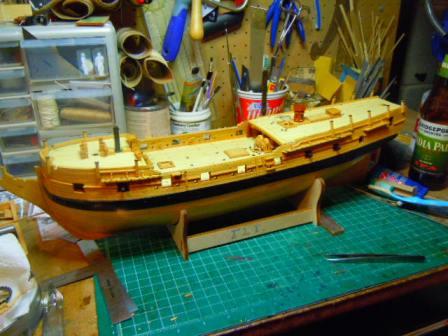
Cheers to all, and thanks for the likes, Bob & Spy!!
Martin
- rafine, Dfell, Landlubber Mike and 4 others
-
7
-
And now for that Drift Rail.
I cut a variety of scraping patterns in hopes of having each rail different. But at this scale, the patterns either failed or looked the same. (The failure has to do with the fact that I'm using a very tiny cutting disk mounted on my milling machine, and it can only cut straight lines.)
One problem I had was in figuring out the placement. I thought logic might dictate that it would line up at the same distance above the channels (which will have their own molding) that the channels lie above the lower rail. But that led to a problem like this:
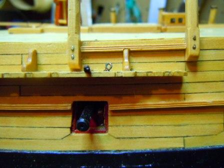
That notch is just too ugly. So I lowered it to this level:

That had the advantage of giving me the line of the plank to follow. One little challenge was to cut a piece small enough to fit between the standard and the swivel gun mount. The boxwood showed once again why it's a pleasure to work with (if the chisel is sharp
 ), and it didn't crumble at all.
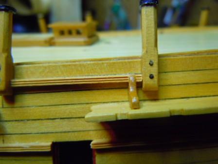
The bigger challenge comes with the actual drift. For this I cut to length the angled piece on some 1/16" thick stock, used my chisels to cut the angle itself and to trim the length down to 1/16" width to match the rest of the molding. Then I simply scraped the pattern in.

The angled joint at the bottom doesn't please me very much. The piece I originally cut before gluing on the drift broke, so I had to make a guess at the angle for the second piece. As a consequence the pattern of the molding doesn't line up, nor does the joint itself. In about 5 minutes, though, I'm going to apply a gentle stroke of the sanding stick to see if I can smooth it out a bit.
There's plenty more to be done on the drift rail, as it moves forward, and along the fo'c'sle. Since my chain saw has gone on strike, I'm not going to be cutting cedar tomorrow, so I might as well cut molding, eh?
Cheers,
Martin
- Mirabell61, maddog33, rafine and 1 other
-
4
-
-
Nice work, as always, Bob. We admirers are the beneficiaries of the "cold" snap in Florida.
I had to notice that you have one of the fine hand chisels from Lee Valley -- Congratulations! Nice tools are as much a pleasure as nice rigging line and wood. Ahh, so many pleasures!
cheers,
Martin (hedonist)
-
Well done, Mike. Setting those rails in, keeping them steady and even has to be great for developing skills in measuring and setting in. Plus, it's surely just plain gratifying to see what a a great job you've done!
Cheers,
Martin
- Eddie, popeye the sailor, Elijah and 2 others
-
5
-
Mike -- That Jet unit is a good one. I'm planning on putting one in my outdoor workshop, since my bandsaw and scrollsaw both put out a surprising amount of sawdust. Even the Byrnes produces a good quantity, so it's wise to employ redundant systems, and to clean up.
Carving is pure pleasure -- sometimes I even think it might go beyond modelling!
Cheers,
Martin
-
-
Hi Don -- That's quite a bit of progress you've made! Well done. The gunport strip looks good to me -- the test lies with seeing whether or not the guns sit in the ports at a consistent height, and yours certainly look right.
I think if my Fly had come with wooden carriages I'd have been tempted to use them, but they were ugly brass things, that even the Easter Bunny would turn away from.
Can't wait to see more!
Martin
-
Mike, I just want to say that your work so far shows your fine skills. This is an interesting ship -- I don't know anything about her history, but the shape of the bow is intriguing to say the least. I had wanted to attend the MSW convention in Mystic (I believe that was '15), but just couldn't get away, so missed a golden opportunity to see the restoration. It's exciting to visit those old vessels, you can really build an understanding of the ways elements work together.
I read your account of clearing the dust when you worked with the ebony. That's important even when working with other woods. I'll boast that I got a dust collector for Christmas, which has already made a difference in keeping my workbench clean. You can check it out here:
http://www.woodcraft.com/product/143300/shopvac-portable-air-cleaner.aspx
The ebony against the holly does look really good. Bravo!
I also agree with you that building up the bulwarks is good practice. I did that with my Rattlesnake, and learned a lot. With the Fly, it seems that a good number of details are simulated rather than actually built in.
Cheers,
Martin
- Eddie, Landlubber Mike, Elijah and 2 others
-
5
-
Thanks for checking in, guys, and thanks to those who clicked the like button.
Bob -- There's a good chance you'll be getting some kind of winter, since what hit here is moving east.
Mike -- Thanks for the compliment. Your Charles W. Morgan is looking really good, and is off to an impressive start.
BE -- Whether your steps stand the temporal test or not, they do respond to the problem of having the steps in the same place as the oar port. Part of the entertainment in modelling is worrying over these little issues and wondering if they belong just to the model or were evident in the 18th-century ship.
Today I'm off to feed my horse a pile of carrots, which she doesn't need.
Cheers,
Martin
-
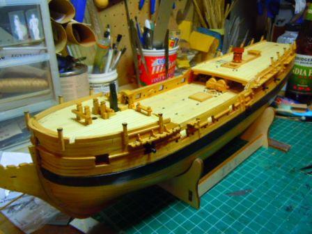
Hello everyone -- The temperature outside is about 8 degrees on the F scale, so it seems like a good time to pick up where I left off on my log some TWO MONTHS ago (
 ).
).I've been attending to details around the upper hull, and mostly the channels. I used 1/16" boxwood stock, cut to width on the Byrnes. I like the look that FFM gives the channels with the tapered section to the rear, so I used that as my model, and marked the notches for the chainplates/deadeyes from the kit-supplied channels. The kits plans don't show the eye bolts (and FFM actually describes them as swivel ring bolts, which would definitely go beyond my ability), but I determined their placement from FFM's diagrams.
Here's the fore channel and stool in place:

You can see that I followed the "controversial" suggestion in FFM (2:156-160) of adding the standards. These really do add a nice touch to the overall appearance of the build -- much like a corbel table on a handsome building. The channels in the above photo struck me as much too small, though, so I pulled them off and made some larger versions.
My procedure was simply to glue a stack of about 4 or 5 pieces of 1/16" stock cut into 7/32" squares, and then marking the rough shape I wanted on the outer layer. I cut the shape out with a jeweller's saw, filed it down close to the line, then unglued the stack. I thus achieved a kind of consistency, but I still needed to shape the individual standards to fit the angle of the bulwark and channel (and to smooth the edges).
Here's the main channel, without any polyurethane:
The length of this channel gave me some problems in placement, as I held it in place with one hand to mark the location of the holes to be drilled in the bulwark for the connecting pins. This was one of those occasions when I could really have used a third hand -- I ended up drilling too many holes, but I don't think they're terribly noticeable (don't look for them, please!).
Next came the fenders and steps. The fenders have a slight taper on the edges facing away from each other, but remain parallel on their inside, facing edges. This makes for a curious look, but interesting nonetheless.
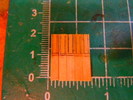
For the steps, i started with 3/32" stock cut into 6-inch strips. I passed these over a .30 inch blade on the Byrnes, first setting the blade 1/16" high and the fence at 1/32" to mark the tread. I then lowered the blade to 1/32" and set the fence to make a 1/16" wide cut. I then cut the individual steps at 1/2" lengths, and notched the sides following the same procedure that I used on the front.
Here's the result:
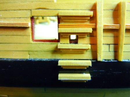
The oar port creates a problem. You can see that I notched the step above the port. And I know that Blue Ensign shortened the step below the port to accommodate the oar. I decided that the oarsman would have to defer to the officers who would use the steps, and kept my lengths consistent.
After this picture was taken, I painted the 2 steps on the wales black, which makes them almost disappear.
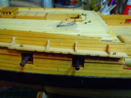
Next I started on the swivel gun mounts. The kit's mounts extend only a short way down the bulwark to allow for the photo-etched decoration. Since I'm neither applying the PE version, nor painting the decoration on, I decided to follow the NMM plans, which show the mounts extending almost all the way to the channels.
The mounts along the fo'c'sle seem odd in that they aren't high enough for a 1:64 sailor to fire the gun while standing. But that does seem to be the correct height, at least on the fo'c'sle.
Following the diagram on FFM 2: 161, I cut 3/4" lengths from 1/8" stock. I measured 1/32" in from each side to mark the bevels:
After I cut the edges down and sanded them, I filed off the bottom:
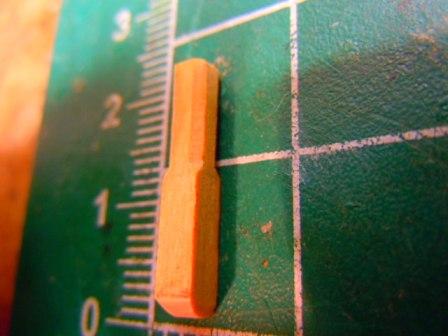
For the reinforcing loop along the top, I simply used a strip of blackened card. To attach the mounts, I cut the heads off some pins, then hammered the point over to simulate a crimped nail:

As I moved around the fo'c'sle, I found that I needed to file the inside of each mount to fit the bulwark properly. They are supposed to lean inward, but mine are pretty much on the vertical.

The temperature is set to rise up into the 40s today, but I think I'll mostly stay in the boatyard (the ground is probably too slippery to be going out and cutting cedar). Who knows, maybe I'll get a posting up sooner than March.
Cheers,
Martin
- rafine, Ryland Craze, Blue Ensign and 5 others
-
8
-
-
-
Nice, Bob, really nice. I think one reason your crowsfeet look so good is that you lined up the holes in the euphroe as evenly as could be. That was the step that continually tripped me up on my one crowsfoot effort (I didn't use a drill press).
Cheers,
Martin
- mtaylor, Red, Blue Ensign and 2 others
-
5
Granado by rafine - FINISHED - Caldercraft - 1:64
in - Kit build logs for subjects built from 1501 - 1750
Posted
Great work, Bob! I'll be elbowing the others out of the way to admire your work on Halifax!
Cheers,
Martin