
HOLIDAY DONATION DRIVE - SUPPORT MSW - DO YOUR PART TO KEEP THIS GREAT FORUM GOING!
×


Martin W
-
Posts
1,412 -
Joined
-
Last visited
Content Type
Profiles
Forums
Gallery
Events
Everything posted by Martin W
-
 I'm with Randy on that. And the stern is the absolute hardest part to plank on this ship. Almost every strake I measured twice, cut once, and dry fitted it, then when I feld happy enough to glue it, saw too late that it didn't look perfect. Sometimes I ripped the offending piece out, and sometimes I looked at my dwindling wood pile and let it go. Keep at it, Martin
 -
Onward -- I've been working on this update over the past few evenings, and am now adding it in between sessions of trying to sort out the photos. Under the heading of “Things I should have done before now” comes the holes for the futtock shrouds. These would have been much easier to cut before I attached the tops to the masts, but now I simply have to deal with it. I drilled locating holes with a small bit in a pin vise, then used a round micro burr on my Dremel to widen the hole, and switched to a square ended burr to smooth the sides of the hole and make it as straight as I could, and finished with an exacto to square the corners and clean the inside enough to allow the chain plate I’m using (from the kit) to pass through. In the process of maneuvering the Dremel around the trestle trees shrouds, I knocked off several cleats, two of which have entered the realm of the Unknown. Here’s a shot of the restored cleat: So, I decided to use the kit’s chain plates, because I just couldn’t think of how to fashion something otherwise. Right now, they’re still just hanging loose in the tops, so if anyone has a suggestion for a more eye-appealing, or more historically accurate solution, I’d love to hear it. Next it was on to the spritsail yard, attaching 4 ringbolt thimbles along the top, lifts & braces, horses and stirrups. This is also where I had to make a decision: I looked at Antscherl’s account of yard slings, and I thought of serving them, but after my earlier experience of having the served line look vastly out of scale, I decided to go with the method of seizing a loop on one side, then passing the two ends over the other side and wrapping one end forward and the other aft onto the spar, and then seizing the resulting loop, like this: – I should also point out here that the Model Shipways rigging plans show a very clear illustration of the spritsail parral that would go here. But I did not have these plans when I was working out that problem. The MS plans look as though the line is served, and maybe, in the months to come I’ll practice, practice, practice on serving line fine enough to look good at this scale. With the spritsail topsail yard, I followed pretty much the same procedure, but without the thimbles, and without stirrups for the horses. And I again followed the above procedure for hanging the yard with slings rather than with parrals. In looking at the MS plans here, I see close by another detail (Oh, had I had these plans back then), and that’s the boomkins. The boomkins seem to be where some of the running rigging from the foremast in addition to the spritsails passes. I have not installed boomkins, so it looks like I’ll be working on yet another problem of how to fit them in at a late stage (luckily, the bowsprit isn’t glued in yet). Getting back to what I did manage happily to do, I also installed a knotted footrope (ie, horse) along the length of the spritsail & jibboom, passing it through a small stirrup at the spritsail topsail. The MS plans show this footrope simply passing over the spritsail topsail yard (I think), and Hahn’s plans are confusing here, so the short stirrup is my solution to the problem of how to hang the footrope in two curves. Deciding to put off figuring out (much less actually doing & making) the traveller and its attendant rigging, I’m going back (maybe fleeing would be the more appropriate verb) to the fore and main yards, which seem a touch simpler. Here are the sizes/dimensions for the blocks & line that I’ve hit on for the Fore & Main Yards (nb: the line is Egyptian cotton and comes from Keith Jewell; I mention that because there seems to be differences among different sources): Braces: 4mm blocks, .3mm line Jeers: 7mm block, .6mm line (Jeer tyes will be .5mm) Clue Garnet: blocks 5 mm, .5mm line Topsail: blocks 5 mm, .5mm line Lifts & Sheets: 3 & 4 mm blocks, respectively, .5mm line For the horses and stirrups, I first cut 4 pieces of tarred .5 mm line about 3 or 4 inches long (these were actually scraps that looked to be about the right length to allow for a loop and then a comfortable clove hitch around the spar), and seized loops at one end with .25mm line. These will become the stirrups. Turning to the horses: I seized one end of a .5mm tarred line to the end of the yard, then put the stirrups on this line about where they belong, and tightened their loops onto the horse, then fastened the other end with a clove hitch to the spar. I let the stirrup hang down about 3/8 of an inch from the middle of the clove hitch to the bottom of the loop. I put some diluted white glue (Weldbond: it dries clear) on the knots & seizings, and let them dry. Once I had the stirrups set, I then finished off the horse by knotting its inner end with a clove hitch on the far side of the sling cleat. When all the knots had dried, I then used a small paint brush to daub diluted glue on the stirrups & horses to stiffen them in a shape that makes them look heavy. Here’s a shot of them drenched in diluted glue (I had to put my hand up, because my cheapo camera insisted on using the background as the focal point): After the horses, I attached the other blocks & lines, marking the appropriate places from the plans. Here’s the final spar: I have to thank Russ again for steering me to the MS plans, which really are helpful: not only do they show the details, but they also contain comments (and unlike the Mamoli plans, they’re in English. Once I’d figured out the configuration of the Main spar, I simply followed it for the Fore spar. Cheers for now, I need to go through my photo file. Martin


- 104 replies
-
- 1
-

-
- rattlesnake
- mamoli
- (and 1 more)
-
Hi Bob -- I just caught up here, and wanted to say your experience really shows. I'll definitely be following your build just to learn from your well honed skills. Cheers, Martin
-
It’s been a long time since I’ve added anything to my rigging log, and since I’m now away from home for a few weeks and unable to work in the shipyard, I thought I’d try to catch up. I brought the rigging plans with me, along with Antscherl’s book, Petersen’s, and Lees’. I also brought the notebook I keep primarily as a way to avoid repeating the mistakes in the future that I’m making now. So, I’m hoping to reconstruct what I managed to get done, which is still a long way from actually setting the masts in and tying everything down. One consequence of not keeping this log up to date regularly is that I’ve almost lost track of what I’ve done, since I’ve often had to go out of the sequence I’d imagined I would be following. One example is that I slowly realized (don’t know exactly when) that the fore & main masts each needed 2 jeer blocks. I used the largest blocks in my collection, 7mm, which you can see here: Because I think crows’ feet just look good, I would really like to rig them on my Rattlesnake, even though neither Mamoli nor Model Shipways shows them. I also see this as a chance to learn & practice something that maybe, just maybe I’ll do better next time. The difficulty lies with the euphroes, that tiny piece of wood that all the crows’ feet have to pass through. I don’t have a mill or drill press, and getting the holes lined up posed some issues. Here you can see my first attempt at trying to drill the holes free hand. There's just one word for that: Yecch! I assure you, gentle reader, that I really did try to get those holes all lined up and evenly spaced – what’s more, I thought I had succeeded until I was done and saw the damage. Anyone who does that kind of work probably shouldn’t be allowed around wood. But after some thought, I decided I just might be able to fashion a kind of jig to hold the little piece of wood so that the holes could be kept in line and at least somewhat evenly spaced. So I marked the spacings on a strip, then ran that strip over the ever-wonderful Byrnes saw with a blade about as wide as the euphroe. That groove (a kind of dado, I guess) I hoped would hold the drill bit steady. Results? Ok, not as perfect as I might accomplish with a drill press, but ok. The real test will come when I actually rig the crows’ feet – I should probably do a trial run first off ship before I commit myself irreversibly by putting holes in the tops. Cheers for now, Martin


-
I'm with both Bob and Janos -- Bob's tutorial has advice I've been looking for a long time. And meanwhile, I've learned about Janos' point that a rotary tool with micro burrs can do quite a bit (at LOW speed). Cheers, Martin
-
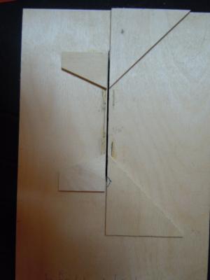
Hi again -- I thought I'd supply a photo of the jig I made. If you look closely, you'll see that in the middle, next to the slot for the saw blade, I've written 5/32" -- that's the distance between the edge of the saw blade and the little strips of wood that I glued onto the plywood base. The idea is that you put the stringer (the side of the stairs that will hold the steps) along the angled miter piece, run it over the blade, then that groove will fit on the little strip of wood. There are mirror images for the jig because one does the right side and t'other does the left. Hope that helps. All credit goes to Allan Y. Cheers, Martin NB: the Attached thumbnail listed below is not missing -- it is the photo above. M

-
Hi guys -- I think your explanation is right on the money, Brian, and I wish I'd read it back in '08 when I was putting the transom blocks in without the foresight of how they'd affect everything else. And JSGerson, I too have learned loads from Bob's practicum, more than I can say (the Ratt is only my 2nd build). In looking just now through the journal I've kept on this build (I was looking for Allan Yedlinsky's instructions for the stairs), I came across several comments of frustration over Bob's waning interest in the project -- the farther along he goes the less guidance he offers. As for Jeff Hayes, well I think it's pretty much unanimous that he's a true blue, diamond guy who can always be counted on. Ok, down to brass tacks: Here's the email Allan Yedlinsky sent me (I don't think he'll mind if I copy it -- and I'd encourage you to buy his book on the Euryalus, where he includes photos of the jig; I found that this worked brilliantly -- the difference between the Before-jig stairs and After-jig stairs is roughly that between ugly and GOOOOOD LOOKING): In general, the stiles are 1.5" to 2" thick and the treads are 1" to 1 1/2"thick for most ladders. To make ladders with different size treds requires multiple sleds. I used a single pass with a blade with a 0.020" kerf as this is 1" at 1/4" scale. I used a single pass with a blade that has a kerf of 0.028" for ladders with thicker treads. These are stock size blades, but the 0.028 is a couple thousandths smaller than it should be for 1 1/2". I doubt anyone will notice the few thousandths difference. The wire guide can still be 0.020 for both tread sizes but you need to remember to seat the stile fully against the wire so the distance between each slot is always the same. If this is not done you could enough have a variation on the distance between treads. (see attached cross section sketch) If you are building at a large or smaller scale, I would use a blade with a kerf that is a close as possible to the thickness you need. Granted some larger ladders may have had thicker treads than 1.5" but we have found no concrete info in Lavery, Steel, Longridgeor other commonly found reference books. Antscherl gives a 1" tread thickness dimension for the lower ladders but does not give a dimension for the upper ladders. He does have a scale sketch in which the treads appear to be about 2" thick, same as the thickness of the stiles on the upper ladders. If you need to make a double pass, I would do it using two sleds. The second sled would have a larger guide wire than the first and the spacing of the wire to the blade would be larger by the difference of the saw blade thickness. If you do not have the micro table saw, Longridge give a good description on cutting these by hand on page 98 of The Anatomy of Nelson's Ships. Cheers, Martin
-
BE -- I understand and sympathize with your eyesight deficiency. A stout pair of coke bottle glasses have long been a primary part of my wardrobe. And I have fallen in love with my Optivisor (and sometimes I use it while looking through the magnifier on my lamp). Cheers, Magoo -- oops, I meant Martin
-
Hi there JSGerson -- It's great to see another Rattlesnake builder!!! I, too, am working through Bob Hun'ts practicum, and so recognize many of the problems you encountered. In fact, some of them made me think that there are plenty of errors in the practicum (e.g. I found the exact same misalignment with the rudder). The several problems with the wood were also there for me -- I've been asking myself for years now how I managed to use up the wood I need for one detail for something else. And when you say the practicum goes "total bogus," well, yup, I know that experience. In fact, once I got going on the rigging, I pretty much figured out that Bob cuts every corner there that he can -- he turns away from Hahn's plan altogether and relies on the Mamoli drawing. That's when I decided to go off on my own: I bought the MS plans, which are the clearest for the rigging, and am consulting the usual other sources -- Antscherl, Lees, Petersen. (I started a log on my rigging some months ago, and haven't been very good at keeping it up. But I am going to get back to it very soon, I promise.) As for those ladders - ai yi yi, the headache they gave me!!! But I got an enormous bit of help from Alan Yedlinsky, who wrote one of the books for Seawatch -- he sent me the info on building a jig that lines up the grooves in the side parts of the stairs (can't remember what they're called), and bing bang boom, it all worked fabulously. This log is especially good, because it traces all the steps of the practicum, pointing out the warts (what, typos in Bob Hunt's practicum? what about the video link for seizing line where his hand move completely out of the frame?) as well as your own struggles. This will be a resource that plenty of folks consult. Cheers, Martin
-
Hi Brian -- your strategy with the gunports paid off well; those are clean looking. As for bumps and depressions, well my Ratt has 'em in spades, one bump for each depression. Some came about through the imcompetence of faring the bulkheads, one or two resulted from strakes giving way as I was working on another part. Y'know, that quarter light is a teaser -- Mamoli has a decoration, but some of the other sources don't show one. By the time I came to deal with it, I looked at the moulding I'd struggled with that runs just where the decoration would go, and thought, "why cut up something I'd done pretty well on to put in something I'm unsure about?" and kept it plain. The angle on that particular opening is pretty odd, so devising something that is both attractive and that keeps the line just seemed too daunting to me at the time. I'll be intrigued to see how you work it out. Cheers, Martin
-
Hi Brian -- It's good to see you're still at it. I like the comparison you draw 'tween Mam & MS. Having now bought the MS plans, I wish, oh wish I'd gotten them much much earlier, since they include a commentary ON the plans about which part does what and why and where it leads. Cheers, Martin
-
Hi BE, it's me again: I think, from reading through this, that I am beginning to understand how your attention to detail, and your fine skills have evolved. Wonderful! Martin
-
These guys are absolutely right, Brian, try out the plane, and in fact try out as much as you can, since spiling is itself something to "try out" in the sense that by doing it you'll figure it out better than reading anything. A good bit of everything we do in modelling (in my view) is simply getting the feel of doing it so that it looks right, and when you get the feel, you'll know it. Keep at it, Martin
-
Hey Brian -- Like Ferrit, I can't respond to question 1, because I didn't use the metal ports. I would imagine, though, that you could glue the planks over the metal, if you're using something that will bond wood & metal both (it's worth a try). As for question 2, again, I'm with Ferrit!!! As an additional point though, I'd suggest that when you get to the decorative rounded parts of that short rail you start with a piece of whatever stock you're using that's long enough to cover the short rail and thick enough to handle the curved decoration. I did NOT do that, and after seeing photos of other models wish I had. There's that big seam between the decoration and the rail itself, and it just won't go away. I had a hard enough time getting the decoration to fit the height and the width that I could have more easily (I imagine) carved the decoration into the end of a longer piece that I could fit in as a single unit. Cheers, Martin
-
It's looking good. Chances are that when it's all done, you'll completely forget about having to do a repair -- you'll just remember that you enjoyed the build. Cheers,\ Martin
-
Which company has the best rigging ropes?
Martin W replied to lamarvalley's topic in Masting, rigging and sails
I've bought rigging line from Keith Jewell of Modelling Timbers (UK), but when I just now check out his website to give you the link, I read that he just recently collapsed, was rushed to the hospital and will be incapacitated for some time. Keith has always given me good service, and I hope he pulls through. I've also bought some linen line from Lloyd Warner, who has an advertisement at the bottom of the MSW home page: Warner Woods West. And I bought a kit for a small hand-cranking rope walk that I found VERY easy to use. I can't say that my results are as stunning as Alex's (thanks for that link, Robert), but they did look more like Rope than just thread. Cheers, Martin -
Hi Algay from another Rattlesnake builder! Are you using the MS kit or the Mamoli? If the MS, then you can just follow the plans, going along with what both JPett (a Ratt's man if ever there was one) and Frankie say. The only somewhat tricky part will be cutting the trestle & crosstrees so that they fit your platform exactly right. And then when you glue them onto the mast, you want to make sure they're square both fore & aft and vertically (in line with the mast). That's where you want to set the mast in the ship, dry fit the trestle & cross trees on the mast -- or maybe while the glue is still a bit pliable -- and look at it from ALL directions. Good luck -- the Ratt is great ship to work on in lots of ways. Cheers, Martin
-
Oh my! Peter, I just popped in and saw what we all fear will happen. You've done some excellent work, and so that snap has to hurt. But you'll definitely work out something that is at least as good. Best, Martin
-
That sounds good, Brian, I'll be looking forward to the update. And I meant to mention earlier that I recall doing the exact same thing with the rudder that you did -- when I set it up against the stern post, I thought, hmmm, why doesn't that look as good as I thought it would? Safe rooms are fairly standard around here. Mine is reinforced concrete on all 4 walls with a concrete ceiling. And as I mentioned, the most important feature is the fridge. Oh, and I'm gettting ready to head off for a few weeks, but I thought I'd take my notes, camera, and rigging plans & books, and try to update my on build log, so you might keep a look out. Cheers, Martin
-
Reeving And Spacing Tool
Martin W replied to guitarguy687's topic in Modeling tools and Workshop Equipment
Thomas -- here's another link: http://www.castyouranchorhobby.com/item--Reeving%20Tool--43030 But after looking at Sarah's jig, I say go that route! Buying tools is always fun, but figuring out a way to make do with what you've got can be even more fun. Cheers, Martin -
Hi Brian -- you've gotten quite a bit done there! I'm liking those windows more and more, especially considering how easy you make the process look. That's a small touch, really, but one where mistakes (of which I made several BIG ones) can detract. I think the biggest problem I had, and couldn't figure out why it was a problem, was cutting out the openings of the lights along the slightly arched lined along the tops. Your strategy of using the clear plastic with the lines drawn is one that I hope I'll remember the next time, 'cause it definitely got the job done, and done very well. A missed tornado is always a relief. I spent Friday evening huddled in my safe room (which does triple duty as my boatyard and beer locker). I heard reports of a twister coming right towards us, and waited for the sirens, but they never blew, so I don't know how close it got, but at least we're still here. My wife is away for several days, and parked her car at the OKC airport, and now we're trying to find out if it still exists. Woohoo! Who sez life on the prairie ain't excitin? Cheers, Martin
-
Hey Brian (that rum was very tasty, thanks Cap'n) -- I like your lights, AND I like your use of the mylar. I struggle with 1/16" sq boxwood, cutting little tiny lap joints and came up with wood frames, but ones that don't look half, even a quarter as good as yours. And, because mine took multiple weeks to do, when they didn't quite work perfectly, I just couldn't bring myself to start over. When I made the doors for the bulkheads, though, I used the clear plastic from an egg carton for the glass. Now that looks ok, except that you can't see them anyway. Cheers Martin
-
May your birthday bring you a keen planker's eye and a steady carver's hand, mate! Martin
-
Hi JPett -- Maybe, just maybe it's time for a progress photo on your treenailing? A sure way to break up the tedium is to take a photo or two. Cheers, Martin (fellow Ratter)
-
X-Y Attachment for Dremel
Martin W replied to Martin W's topic in Modeling tools and Workshop Equipment
Well, I'm eagerly awaiting your trials with the equipment, and your review. it looks awfully versatile, and if Vanda Lay takes your advice to heart, it could possibly be the solution to the big problem of how a modeller on a budget can stock his or her shipyard. Cheers, Martin


