HOLIDAY DONATION DRIVE - SUPPORT MSW - DO YOUR PART TO KEEP THIS GREAT FORUM GOING!
×

Justin P.
-
Posts
1,008 -
Joined
Content Type
Profiles
Forums
Gallery
Events
Everything posted by Justin P.
-
 Your double-planking turned out very nice. Though it looked like the first layer looked nice too. I assume you wont be coppering over it? Other details look well executed too.
 -
Indeed! I pieced this together myself when I went back and more carefully read through some of the logs. Thanks!
-
Quality building jig
Justin P. replied to PAnderson's topic in Building, Framing, Planking and plating a ships hull and deck
I have the Model Zone slip and while its great for bulkheads, it is otherwise unwieldy and gets in the way. It really isnt suitable for steps beyond early construction of the hull. Planking and so forth, no way. I think you are better off in the end finding or designing something else. I used mine once, and would be happy to sell it but I honestly do not think it is worth what it would cost to ship - I have the big one. As for your models... dear me, now off to inspect my own wall-hangings and model shelves! -
Nevermind, I think I figured out the reference!
-
Thanks Ainars, I just caught up on your build, wow! Out of curiousity did you ever find a good resource for the well and locker mods you incorporated into your build? Ive noticed sever references to the "well mod" but havent found the right post on it. Thanks for checking in.
-
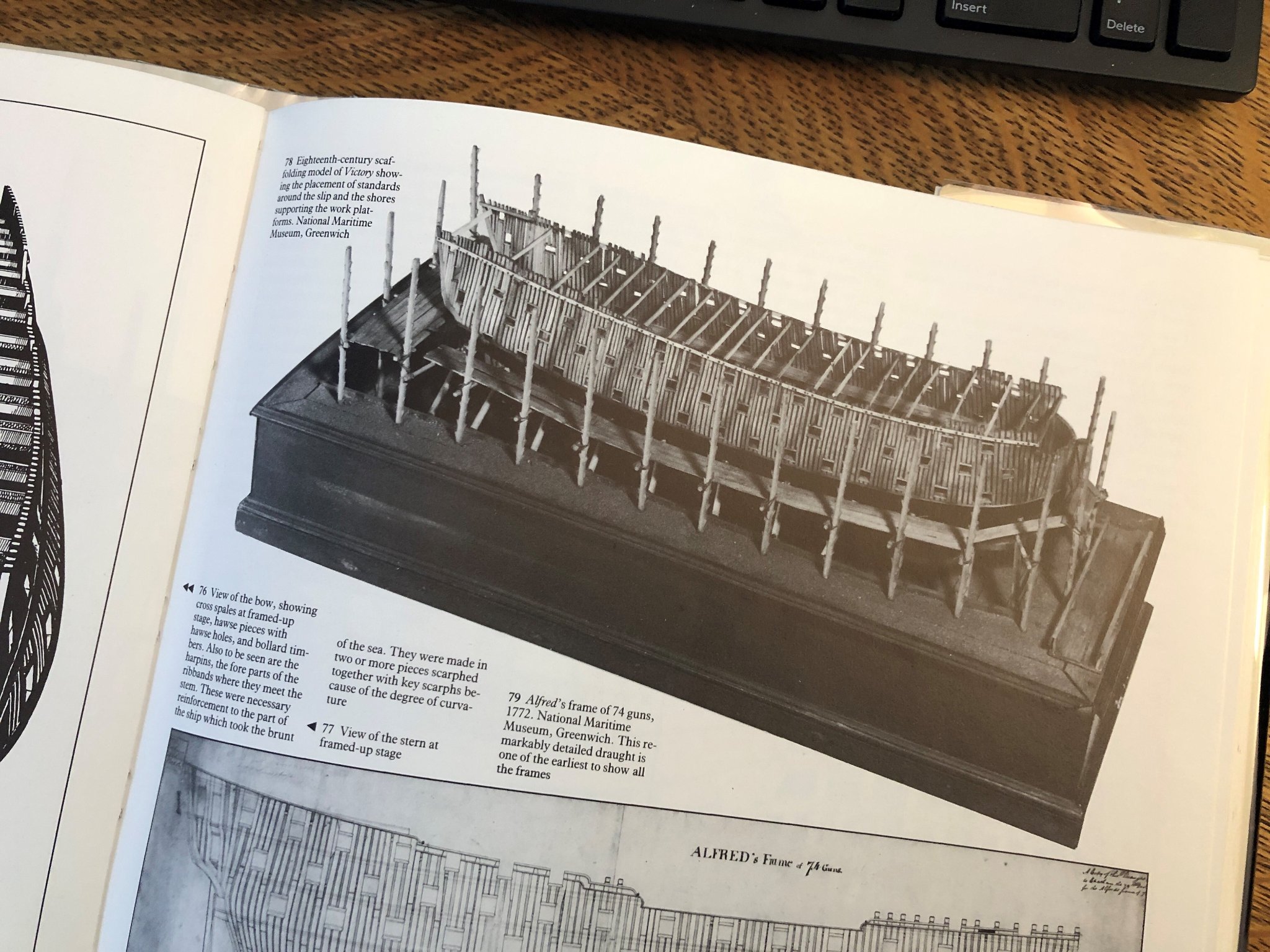
Look to Dodds & Moore - "Building the Wooden Fighting Ship" They have many examples of ships in various states of construction in dry dock, including Victory (see image).

-
Reading this is giving me an anxiety attack. I should have done this too...
-
Thats just the kind of simple solution that always seem to escape me, thank you for sharing! Ive been WAY over thinking it. Wanted to add after looking at the shared post, your coppering is superb. Just beautiful.
- 950 replies
-
- 2
-

-

-
- syren
- model shipways
- (and 1 more)
-
Looking great. Can I ask how you worked out your hull cradle? Ive been going over whether to knock one out as I dont really want to continue using a keel clamp now that my coppering is done. Did you use a template or just reckoning? Forgive me is this is covered in your build log somewhere already...
- 950 replies
-
- 1
-
-
- syren
- model shipways
- (and 1 more)
-
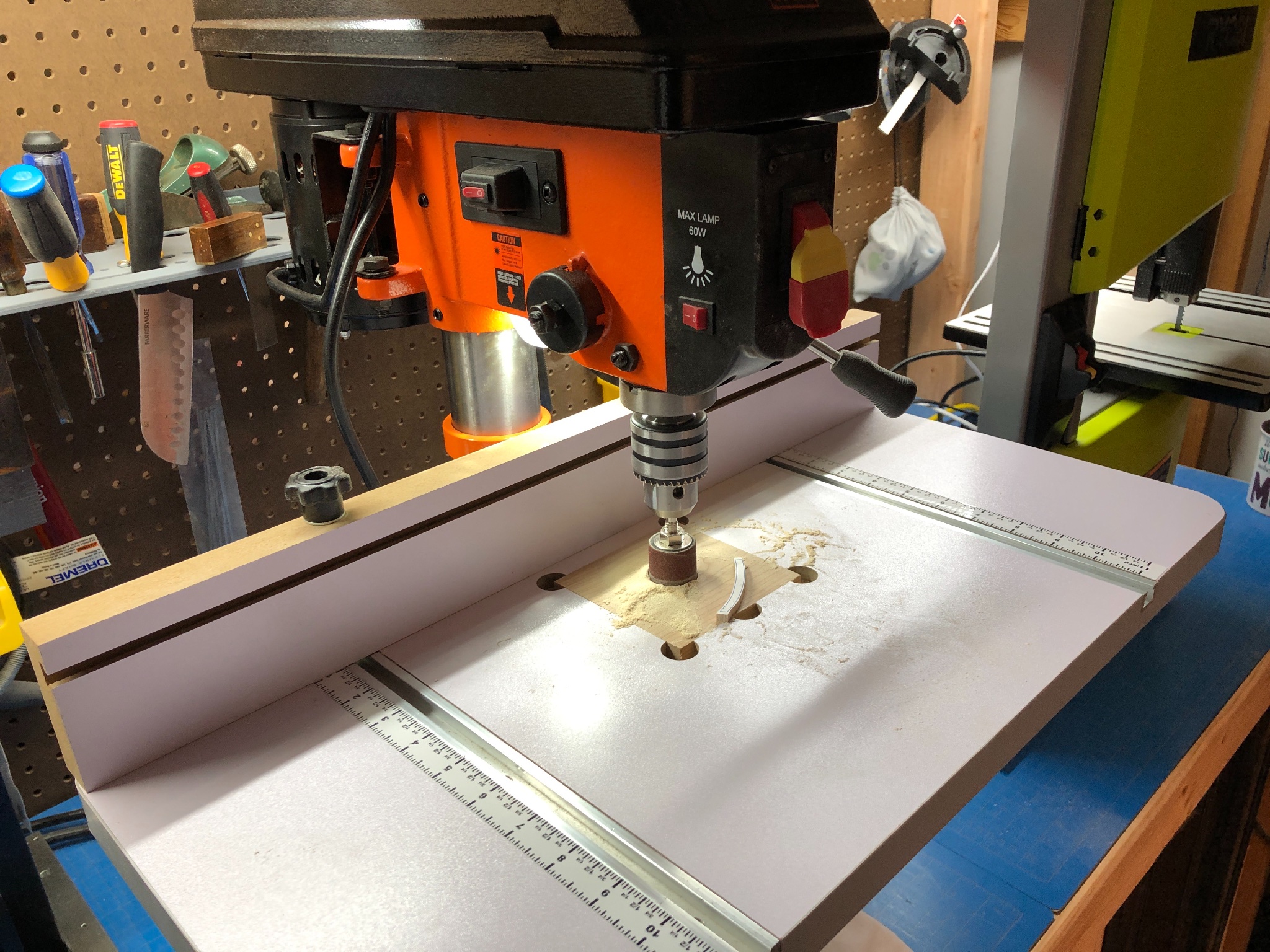
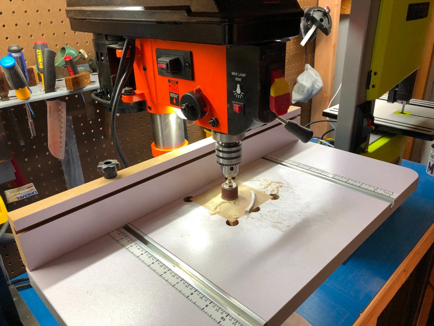
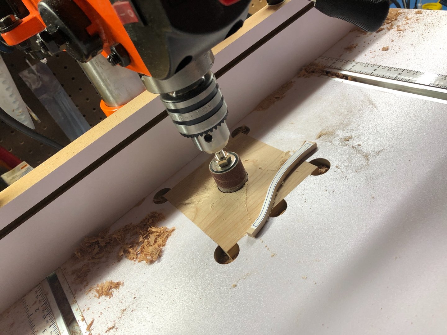
I put together a very effective setup with no oscillation using a drill press and table. Speed is variable so easy to keep in the right area to prevent burn. 120 grit or above leaves a nice finish on hardwood (to be finish sanded at the final stage by hand). The whole setup out the door cost me less than $200 and I now have a drill press. As previously mentioned the compression drums do get out of wack above about 1.5" diameter and no amount of centering seems to help. If the drum stays under 1.5" Ive had no problems at all. Adding a tilt to the table shouldn't be too hard with some thought put into the construction of the insert. I clamp a vac hose close up and all the dust gets sucked away during heavy use.
-
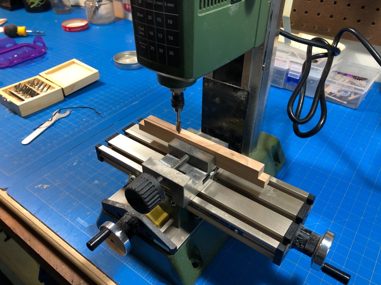
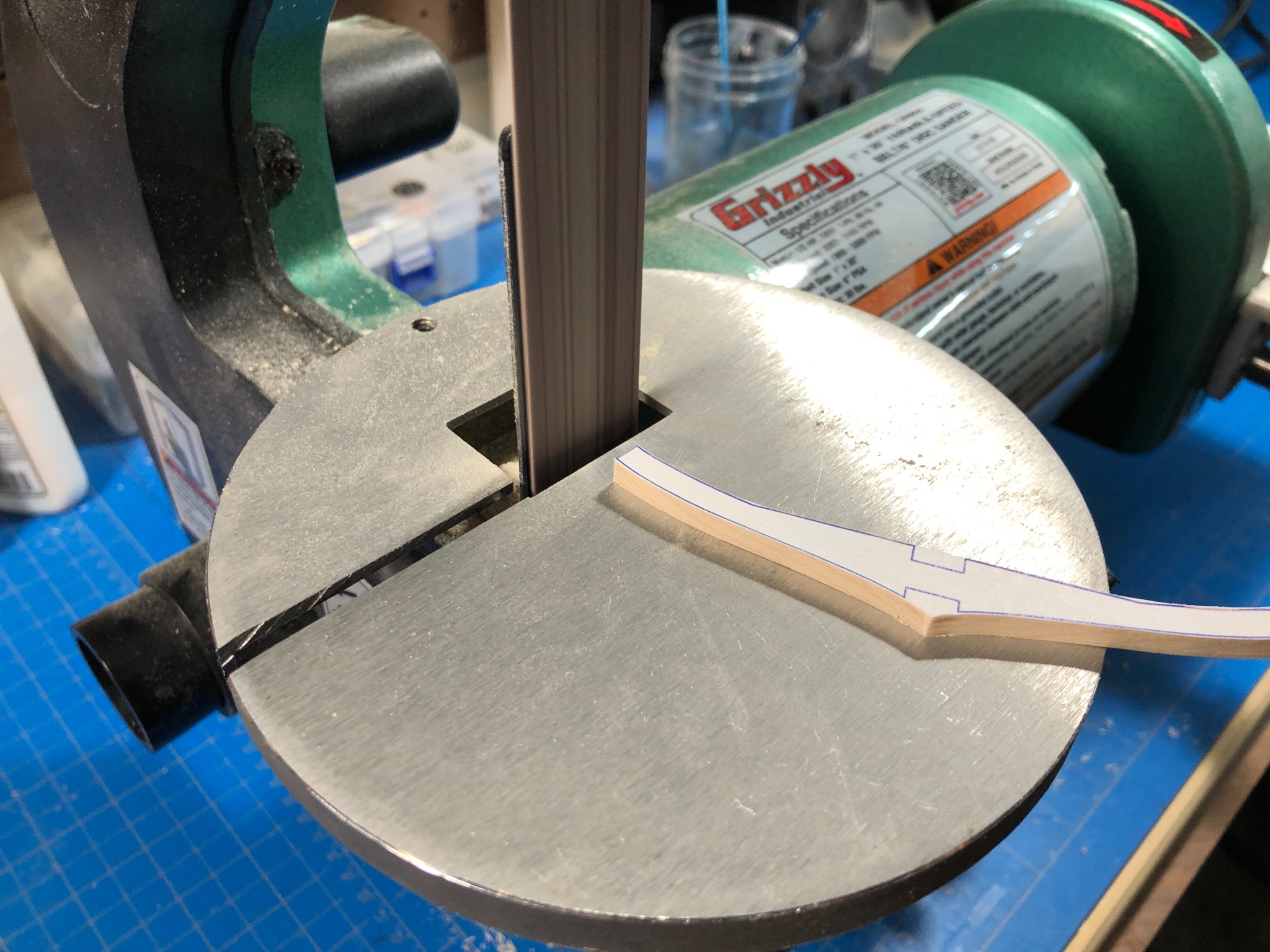
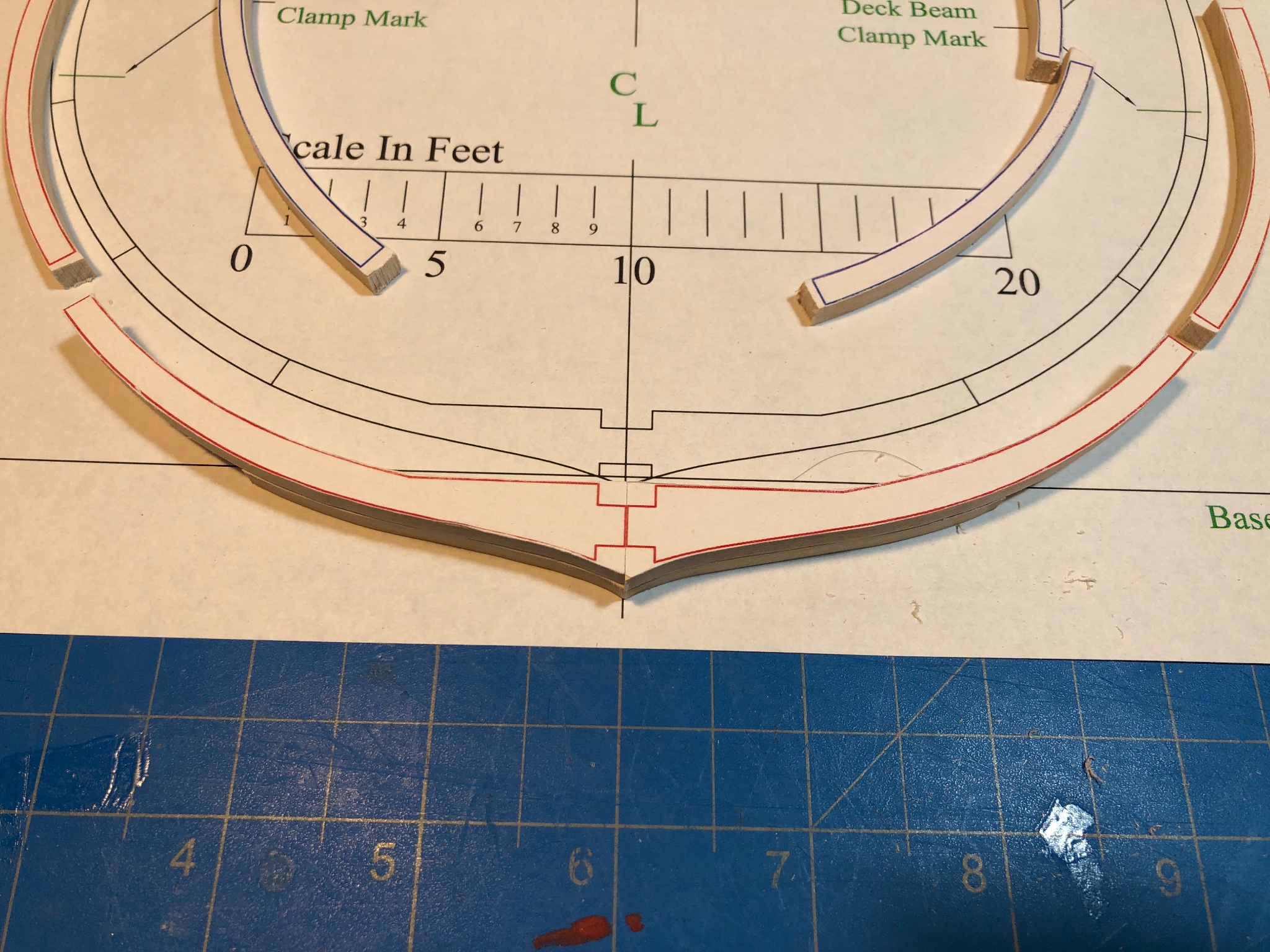
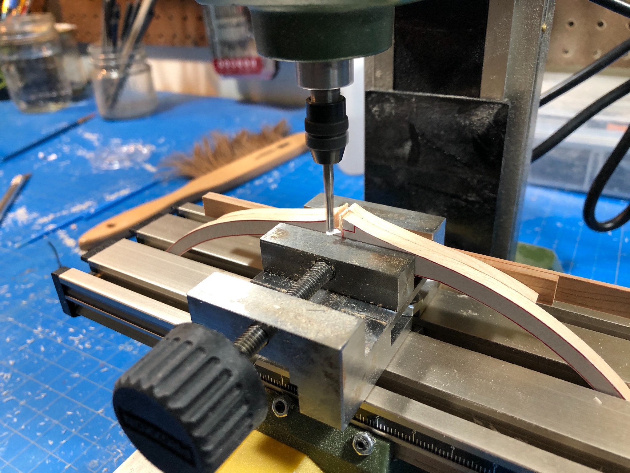
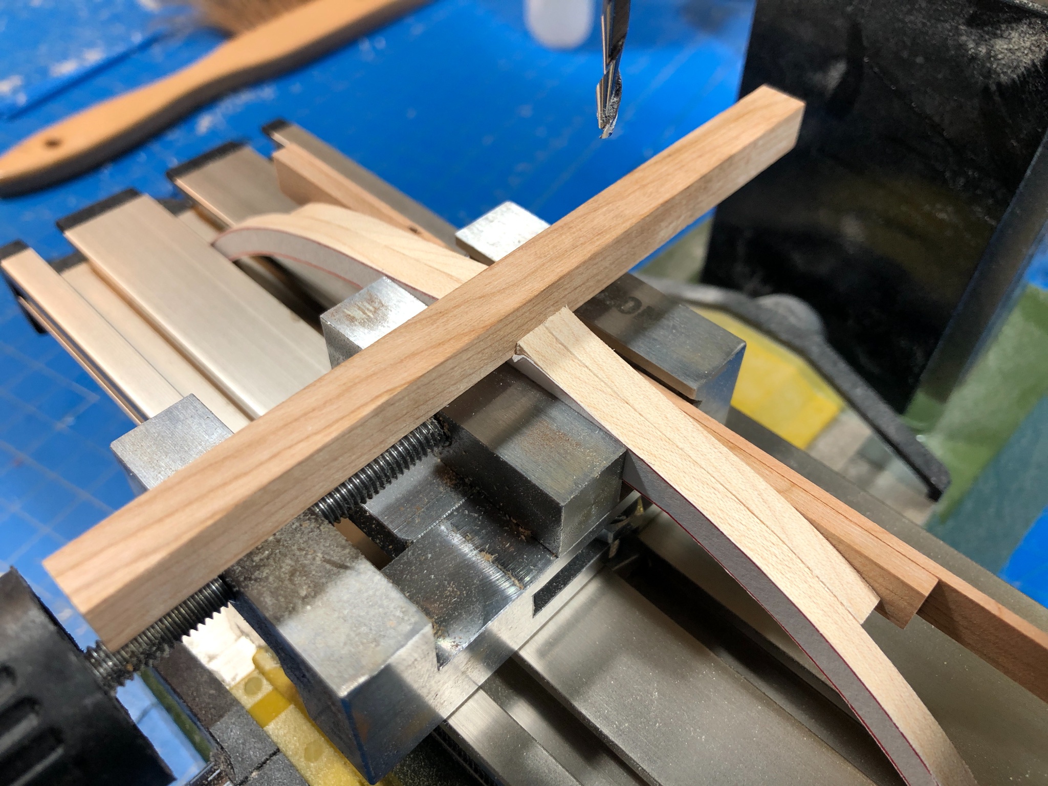
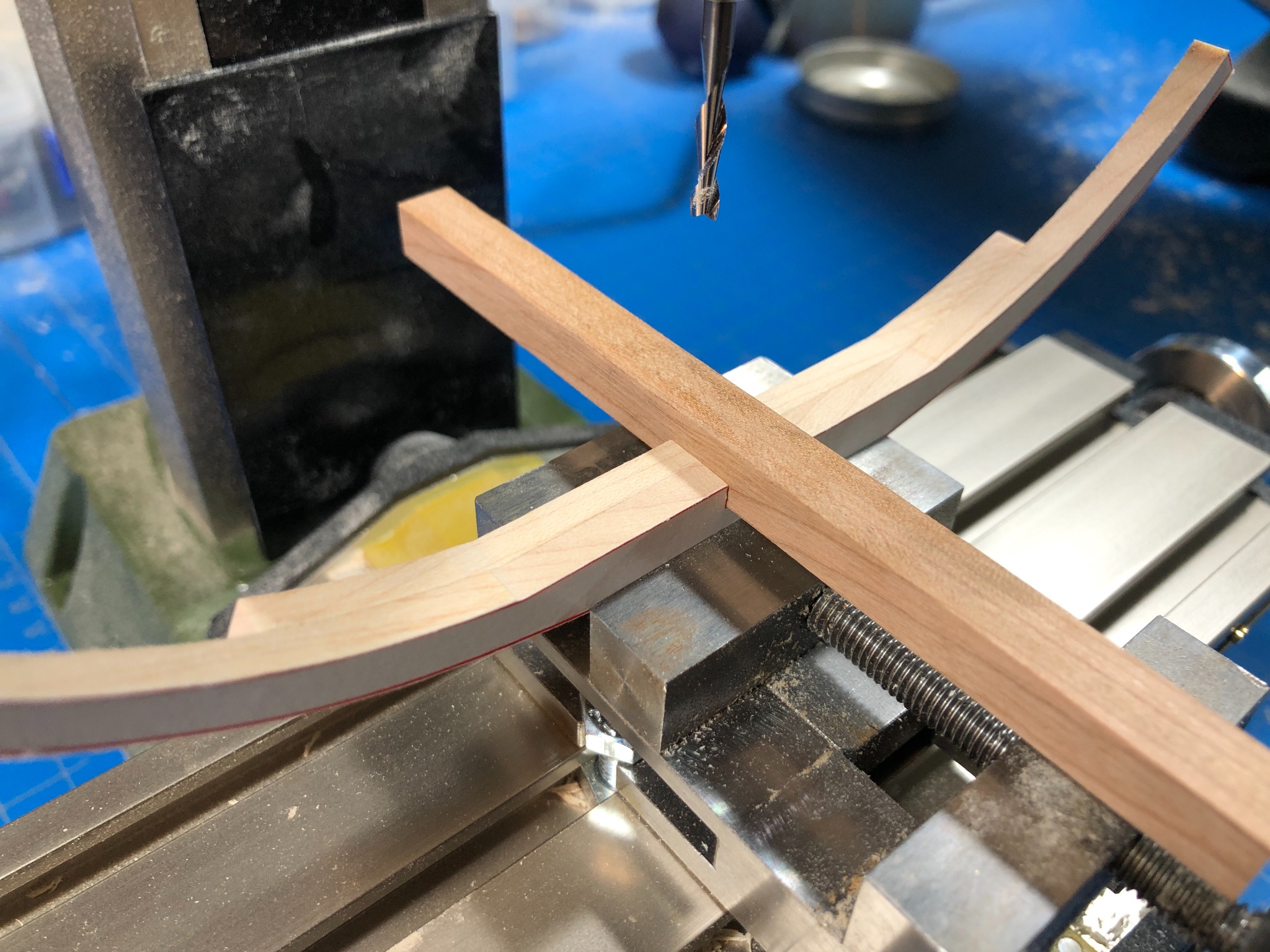
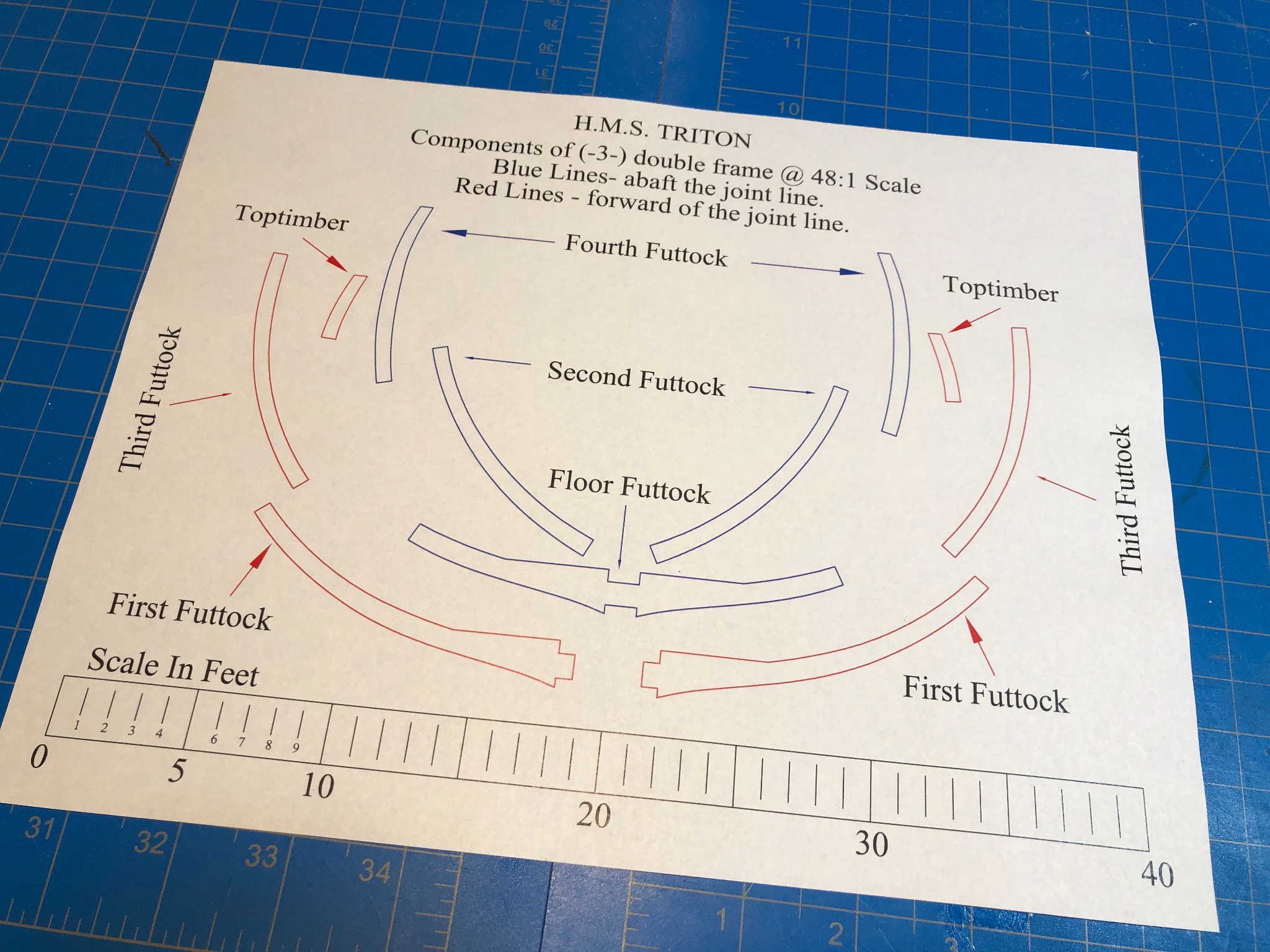
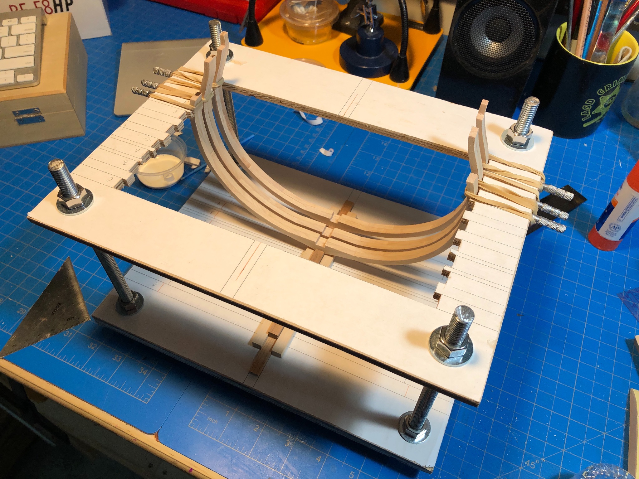
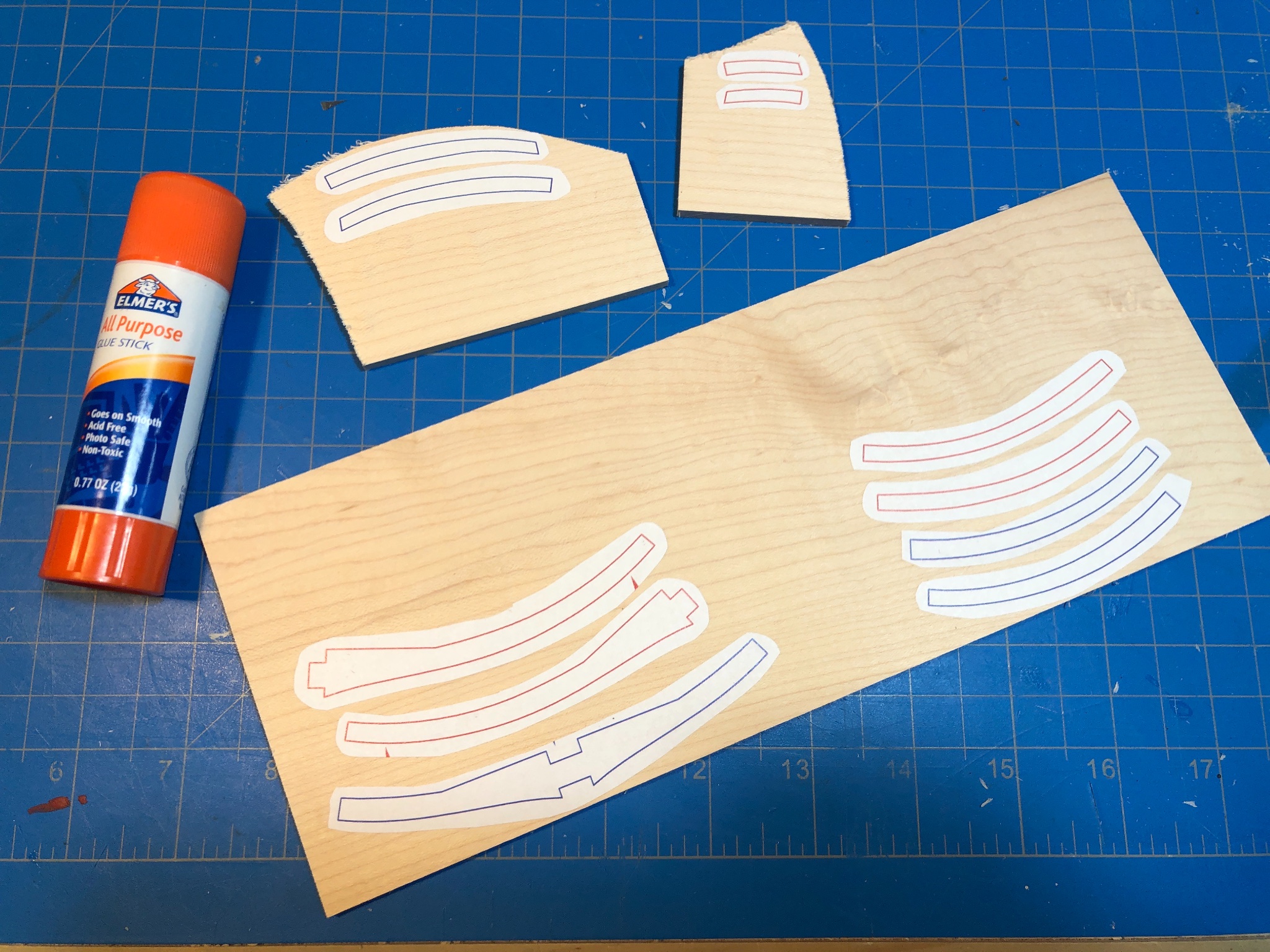
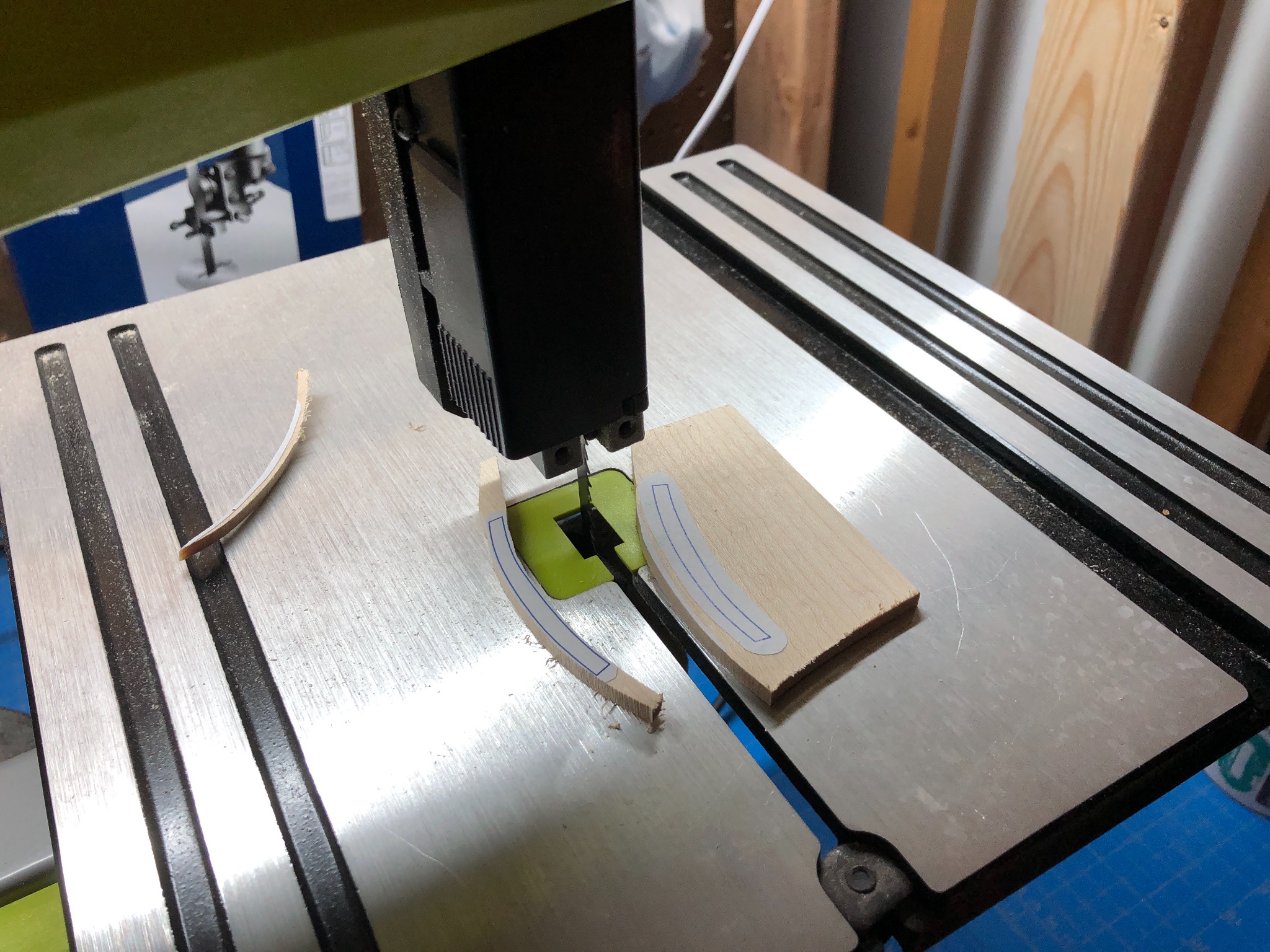
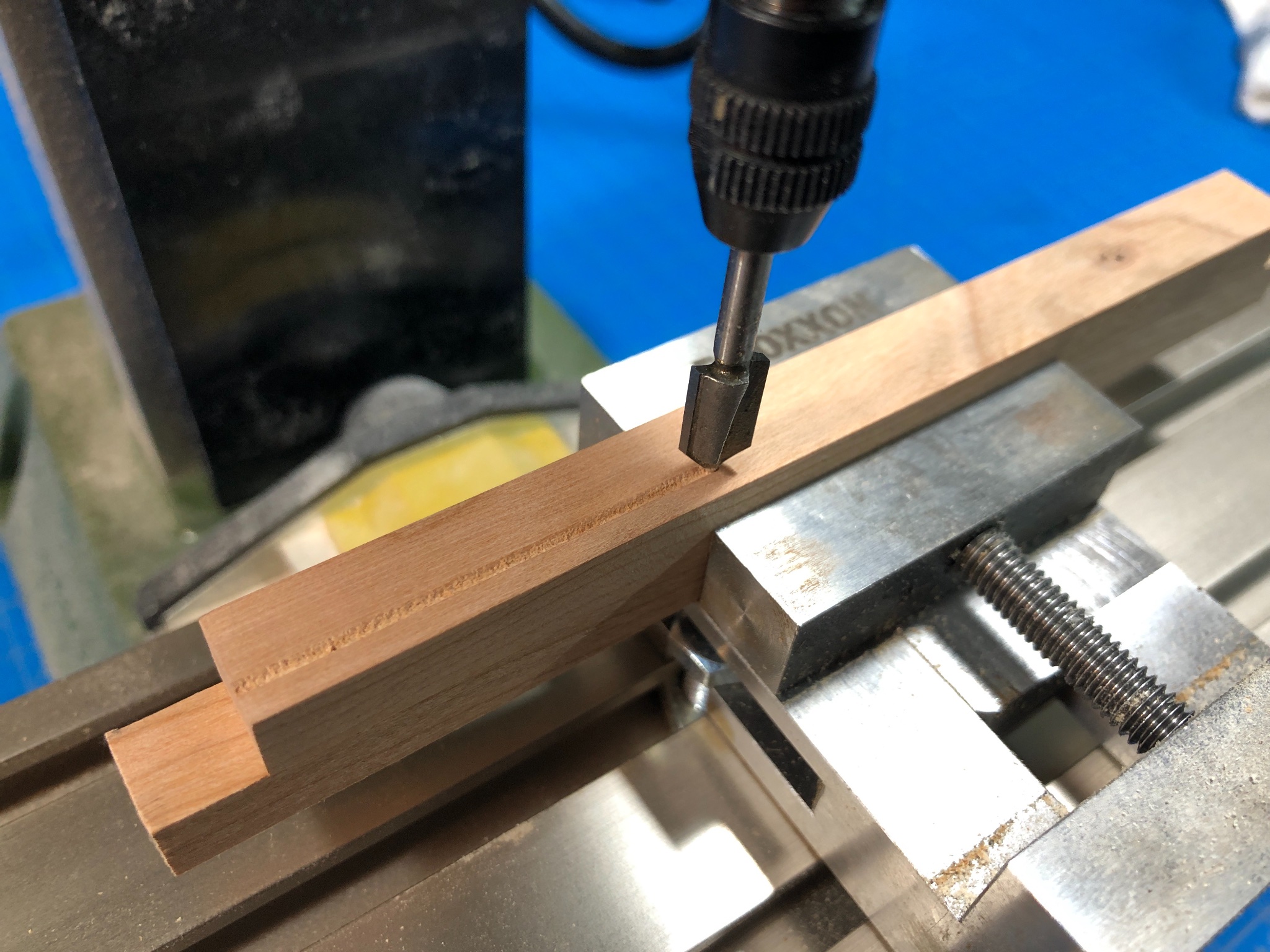
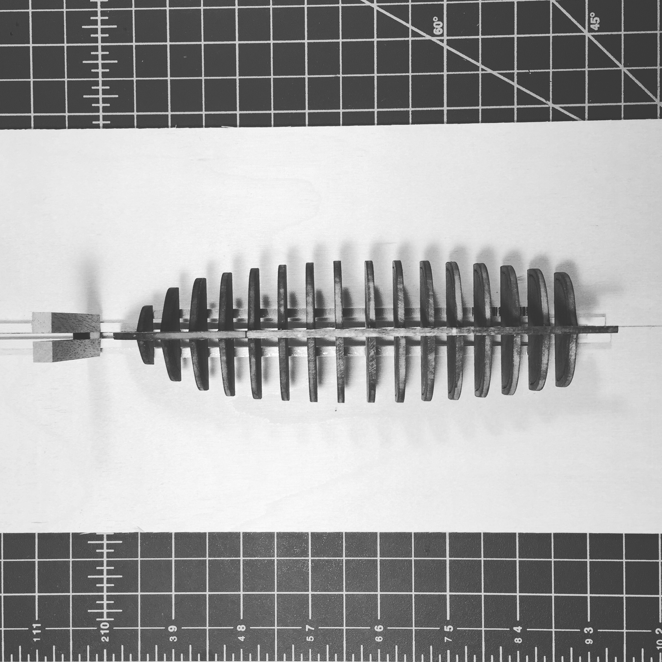
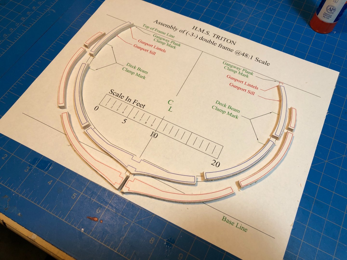
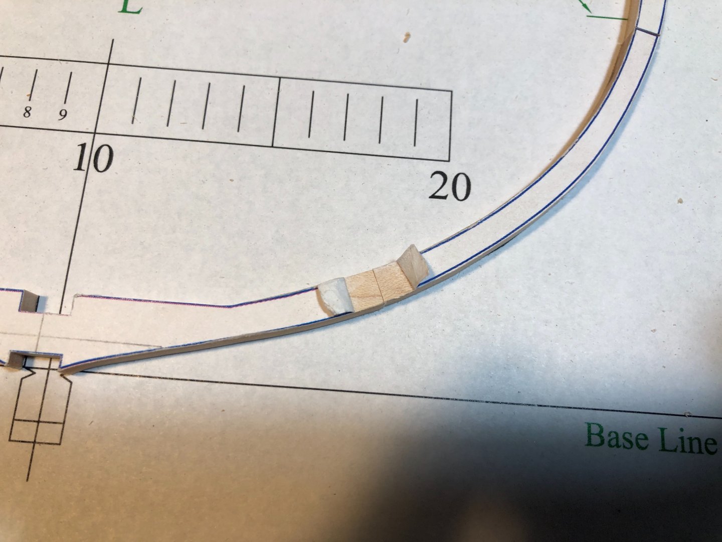
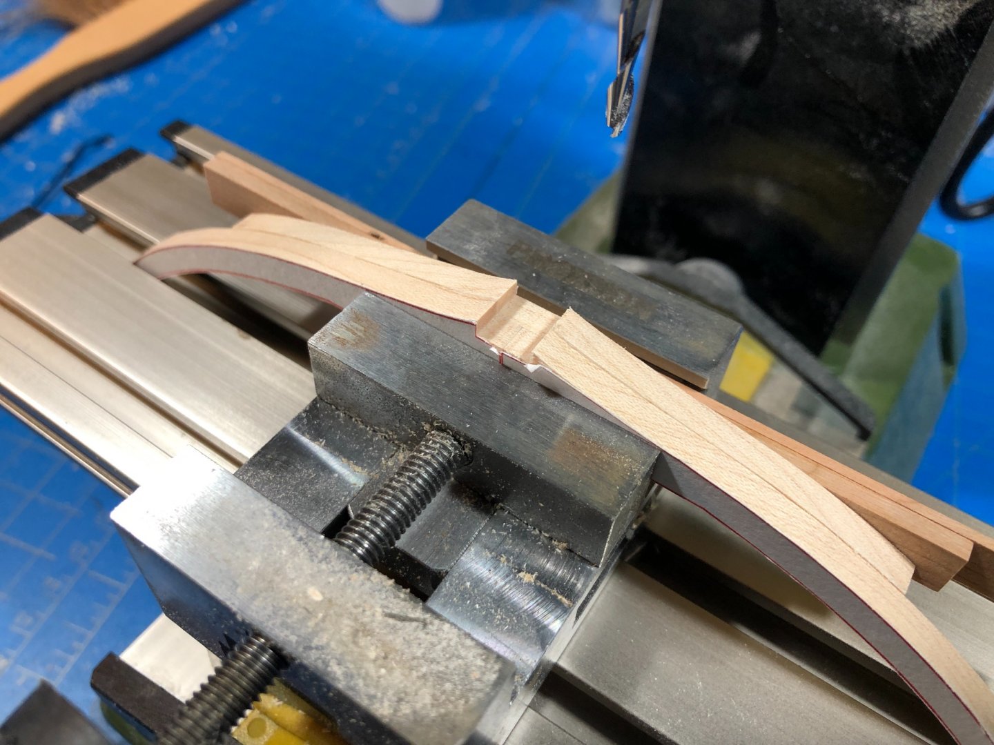
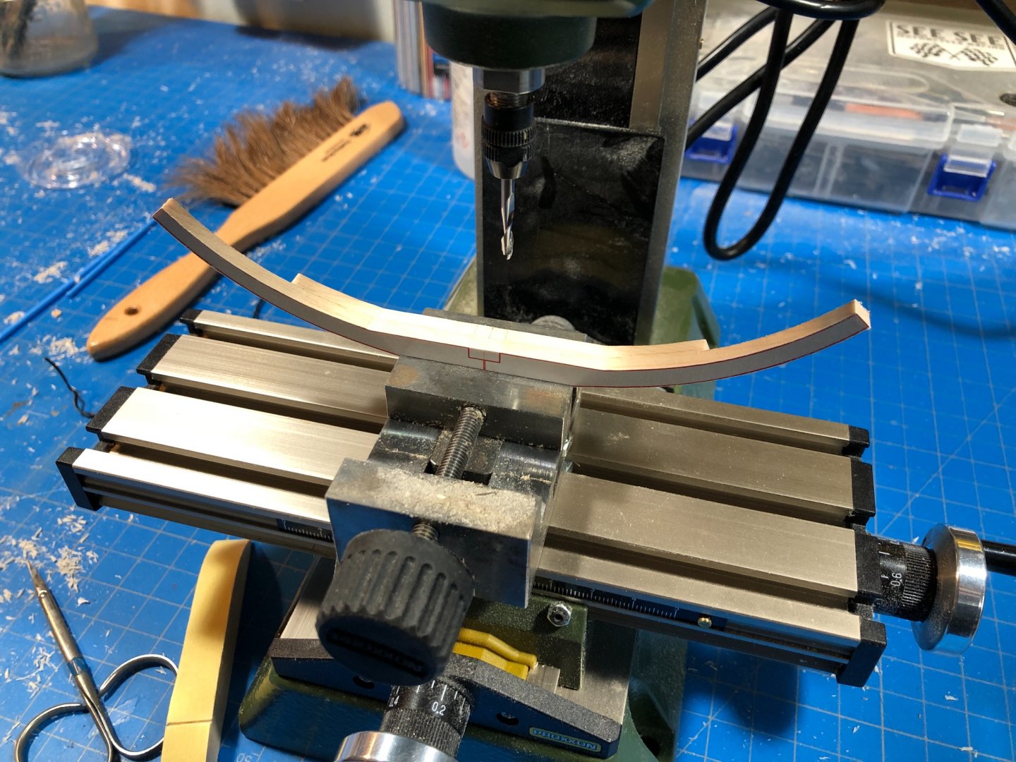
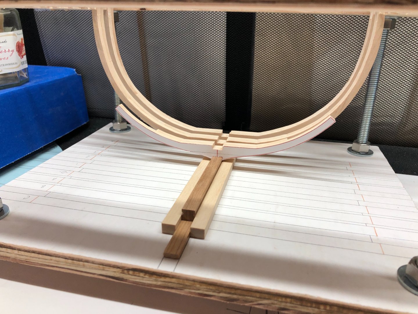
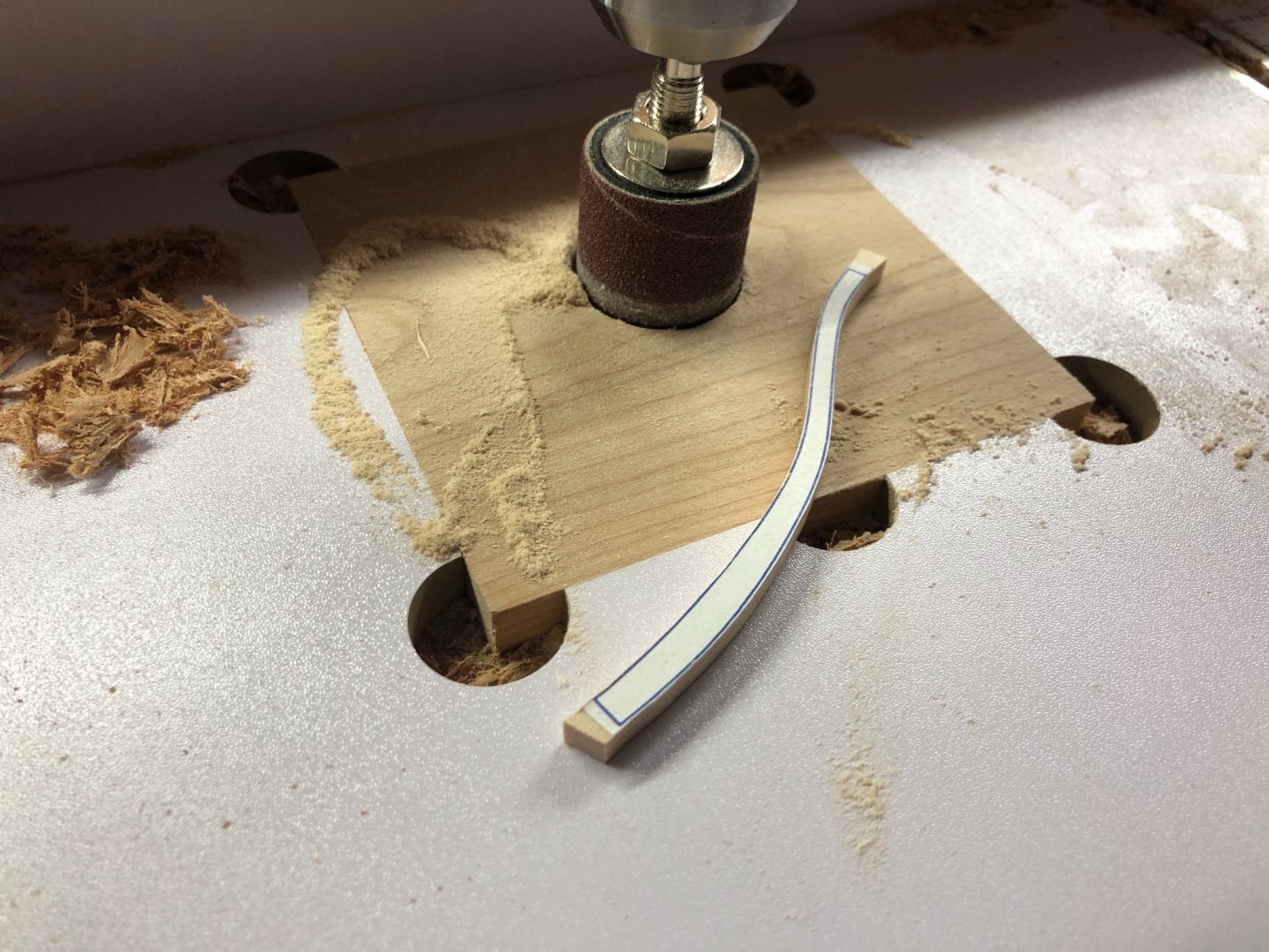
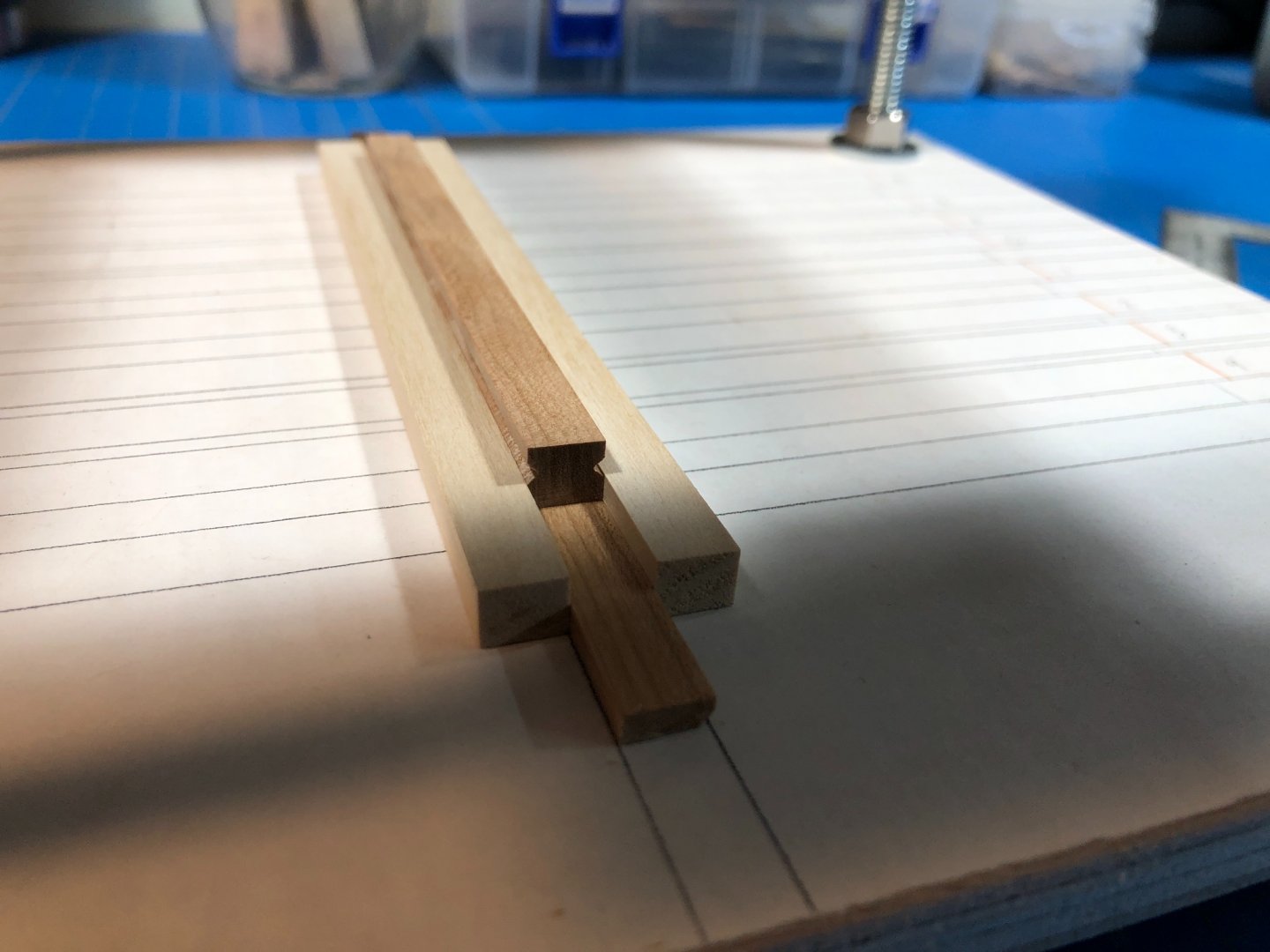
Frame construction process... So as promised I'll outline in more detail how Im constructing my frames. The reason is primarily to provide a somewhat comprehensive set-by-step for anyone thinking about starting this build. Im sure its well documented in numerous iterations by many more skilled modelers than I, but will throw my lot in in case its helpful to someone. My process is rather power-tool heavy, but I find the time I save using power-tools allows me a little extra to be thinking through and prototyping next steps. Not that Im in a hurry, but with kids, a full-time job and the honey-do list, my time in the yard must be used efficiently ;). Some of this will be repetitive, so Ill keep that bit short.. Step 1: Cutting and laying out the frame components on the chosen material. Im using Maple and Elmers Glue Stick here which Ive mentioned before as being the most reversible (I think) of the various options Ive read about. Giving myself a "handle" but mounting the components at one end of the piece keeps my fingers away from the blade. Step 2: Roughing out. I chose to cut my pieces out using a 9" Ryobi bandsaw. I find this a more pleasant experience than using a scroll saw and noticed that my paper stays firmly attached as the blade only runs downward and there is no friction pulling back upwards and lifting the paper - a problem Ive noticed others have encountered. One thing Ive noticed about these bandsaws is that they really need the time to be accurately setup otherwise they cut like a cheap power tool. They can be very good, just put the time in. I cut up to about 1-2mm from the plan line to give plenty of room for finishing to a more accurate shape. Step 3: Shaping. Im using a drum sander setup to bring the frame pieces down to their "pre-faired" shaped. Im using a 120 grit drum mounted to a drill press and take these down to just outside of the plan line. As recommended by @ChadB in his build log, it is very important to leave the ends with 3-4mm worth of material so really only focus on the outside edges during this step. Step 4: Fitting and Cutting the Floor and 1st Futtocks So once I reach this phase all the parts have been taken down to the plan line, leaving the ends long. The first two components I work on are the floor futtocks. I first use a belt sander using 400 grit, being careful to square the machine as precisely as I can and take the ends of the first futtocks down until they meet cleanly at the center when aligned over the floor futtock which sits abaft (behind) the join. Note here I have left the Keel and Keelson notches uncut. After being satisfied with the join between the first futtocks I then peel the paper off the floor futtock and join the three pieces using wood glue. Not well pictured is that Ive transferred marks of the keelson and keel notches to the top and bottom faces of the wood. I then mount this assembly into my Proxxon MF70 mill and set about cutting out the notches, with a fitting step in between using the Cherry keelson and a duplicate keel piece I cut earlier. This is followed by a final fitting in the jig to check level. Also not well pictured is an alignment mark that I use to be sure the assembly is mounted into the mill vice absolutely level. Step 5: Final Assembly. The rest of the process is pretty straightforward. I first build out the blue layer, carefully sanding the ends down and checking the fit and curvature of the frame against the plans. I use a brush with water to soften and remove each layer of paper after peeling back the ends to finalize the fit (also a trick I got from Chadb's build.) Then its just about repeating these same sanding and fitting steps for red frame components and removing all the paper. I give the whole thing a fine sanding over the face and fit into the jig for later.


-
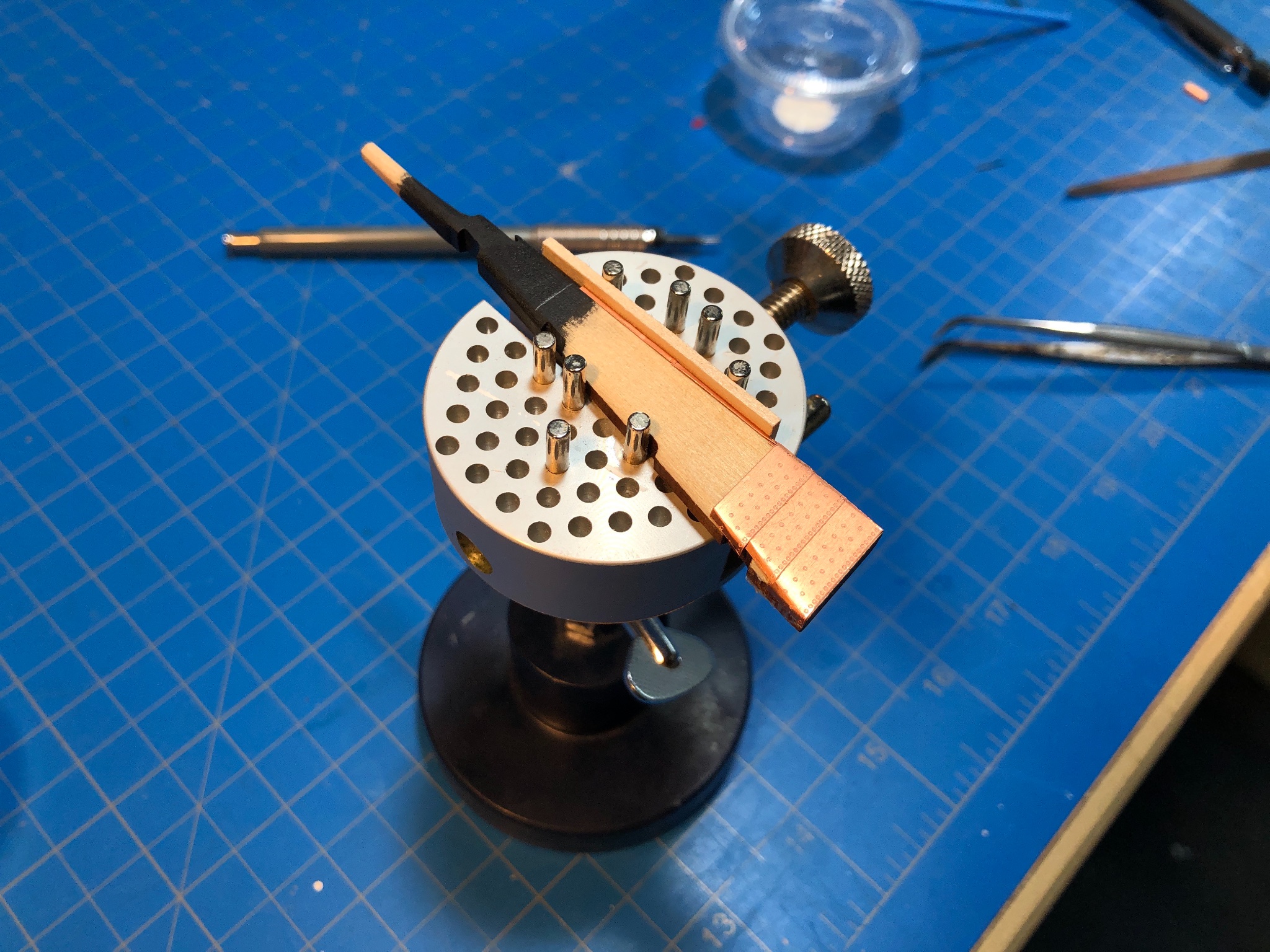
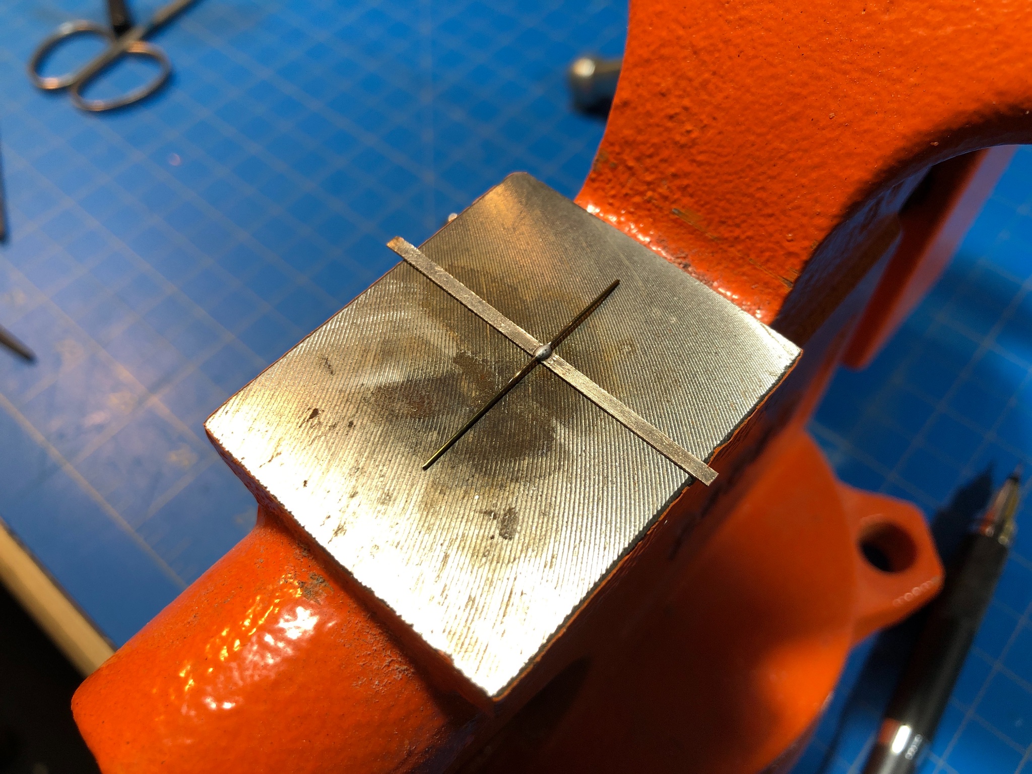
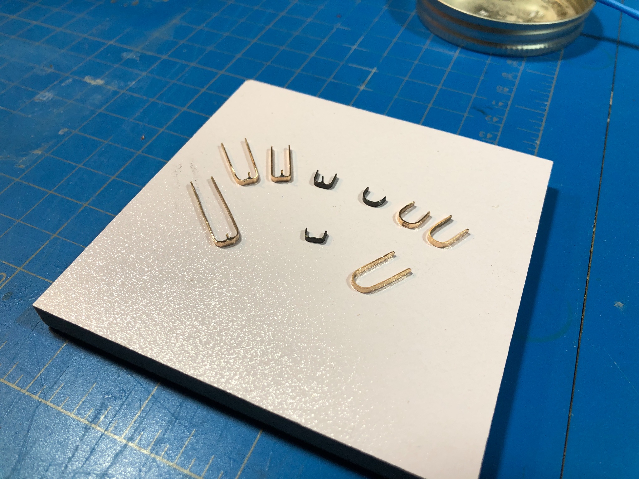
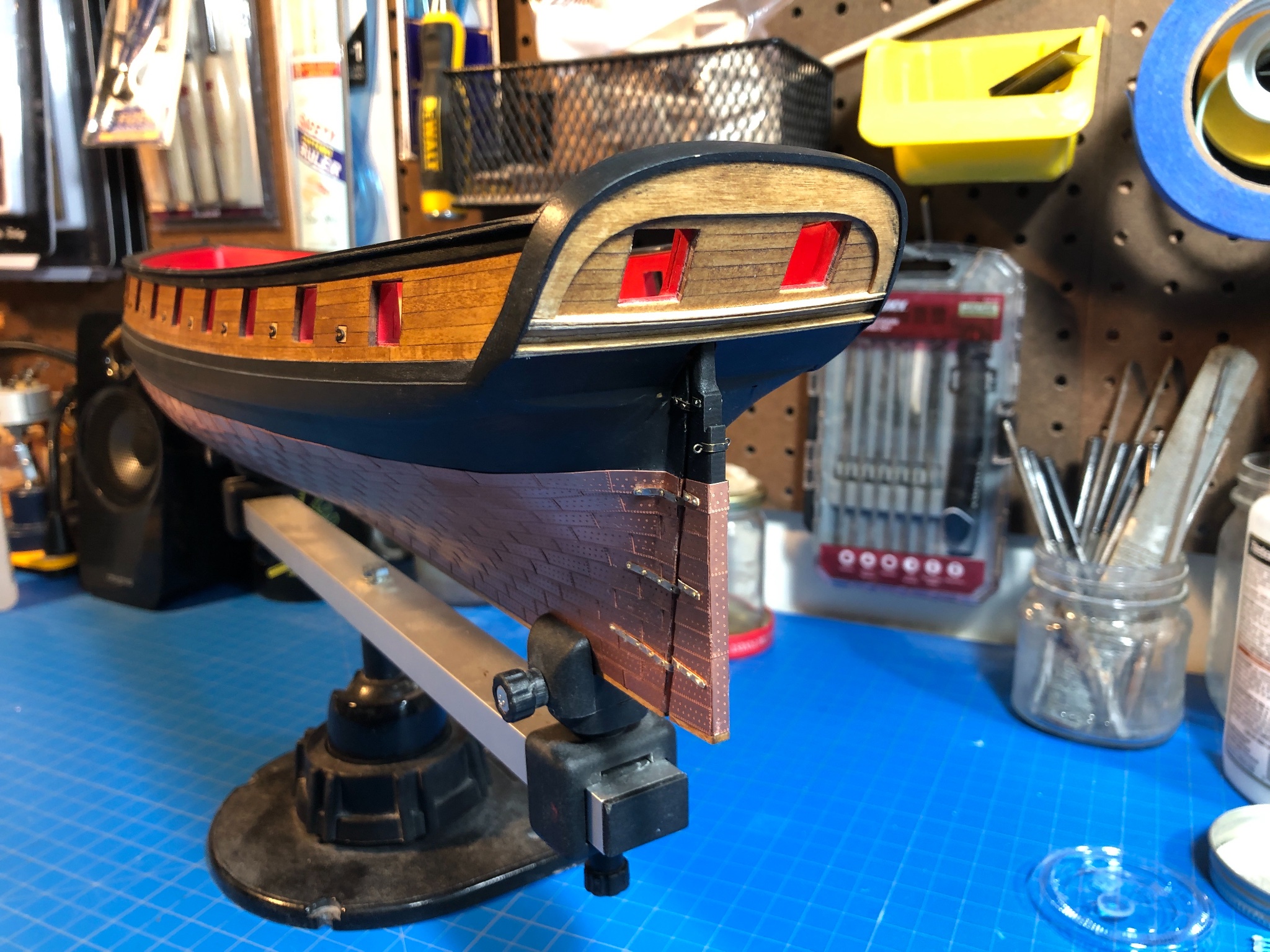
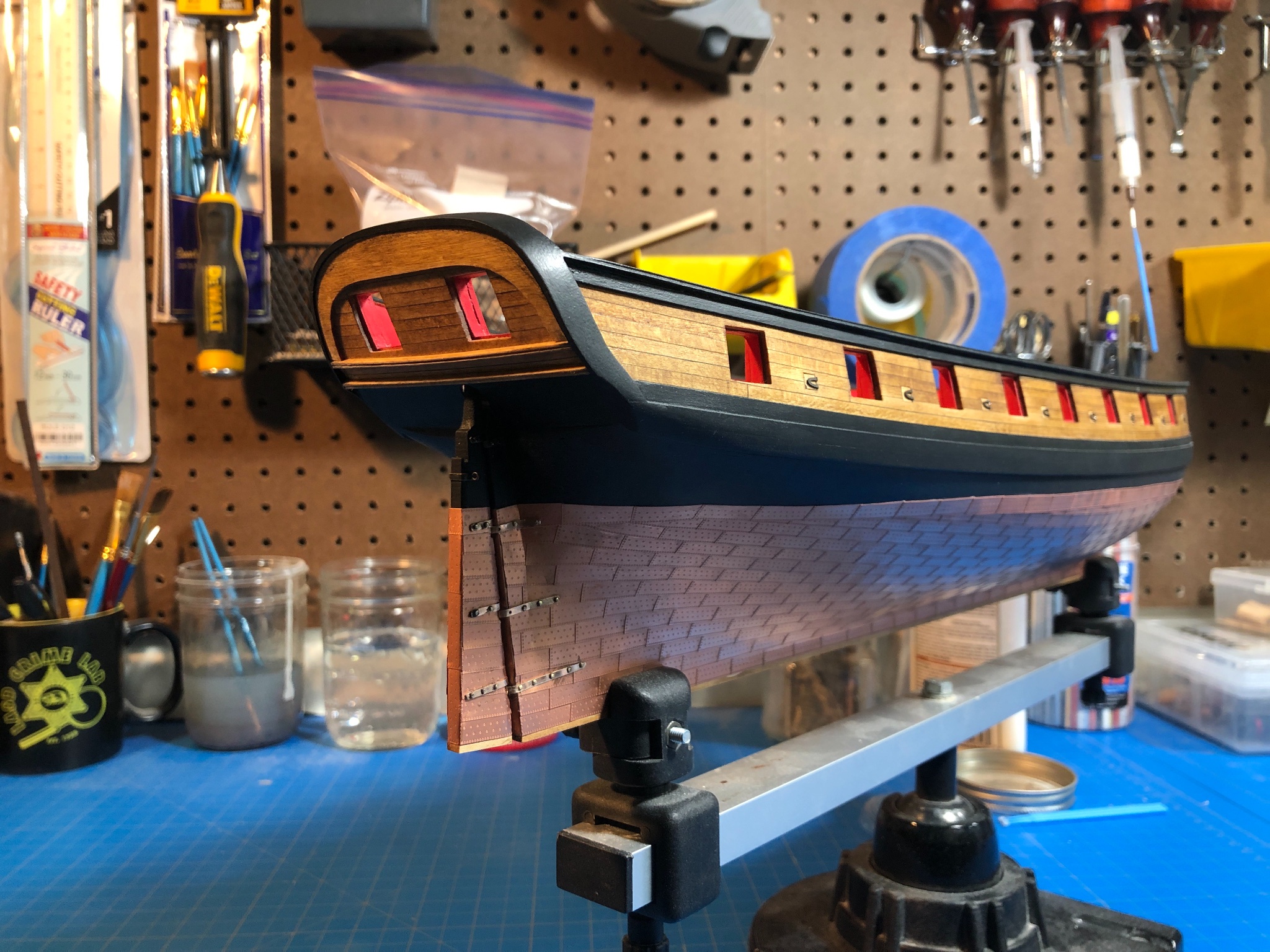
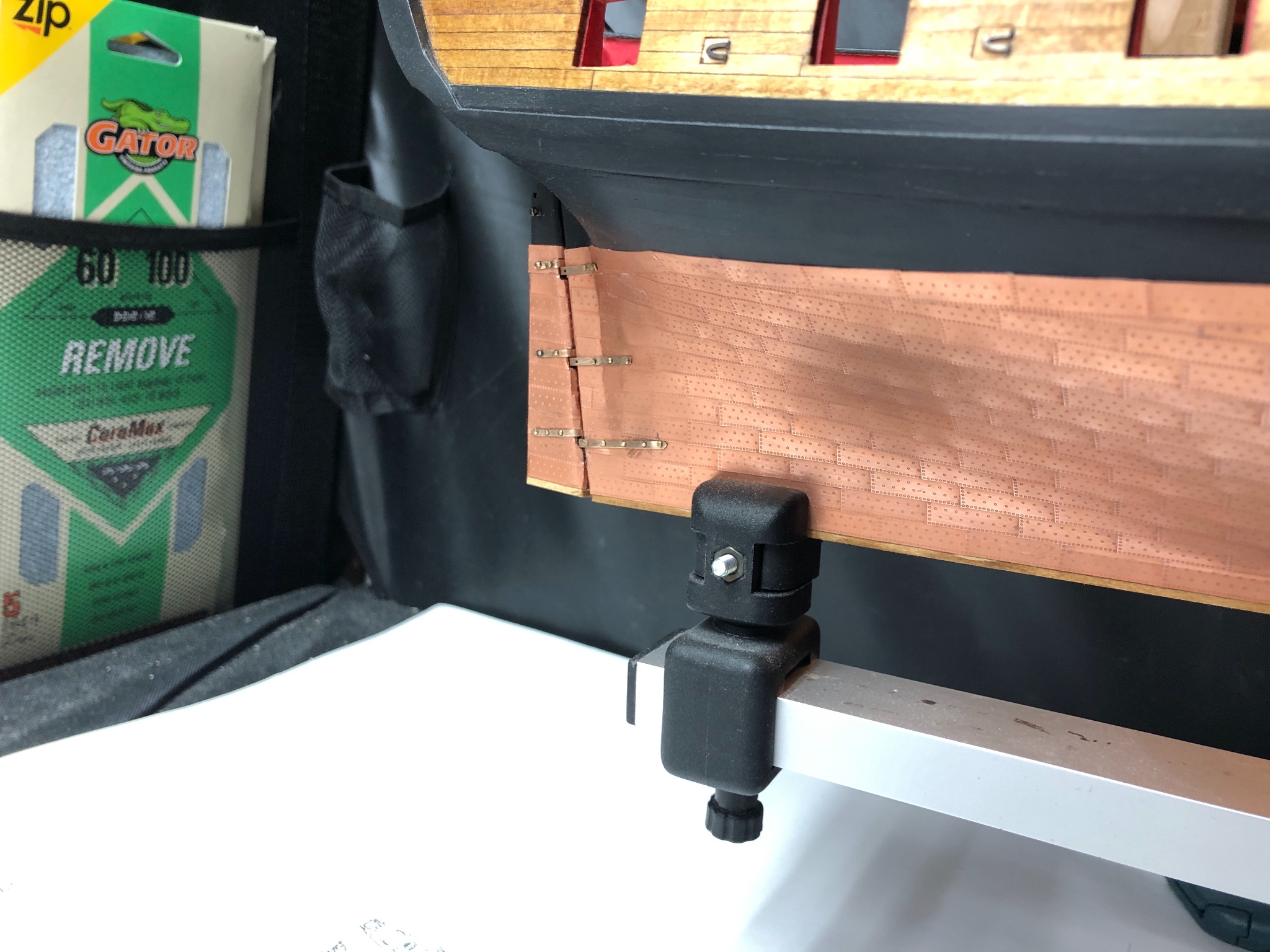
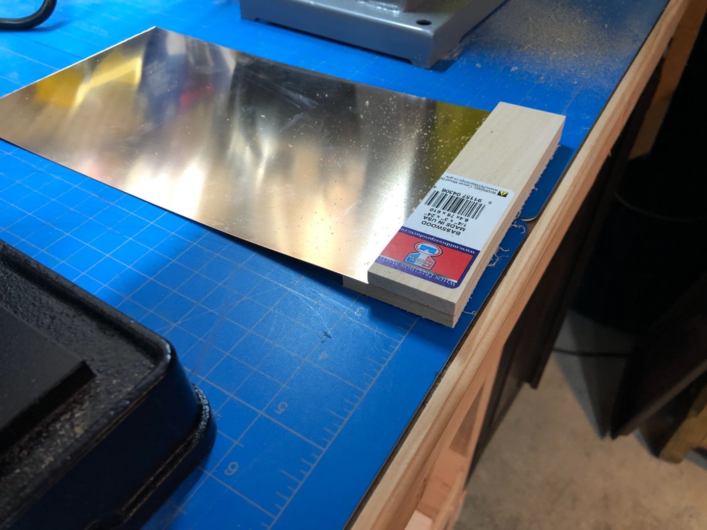
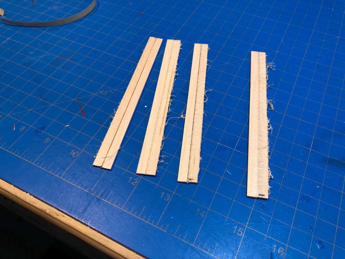
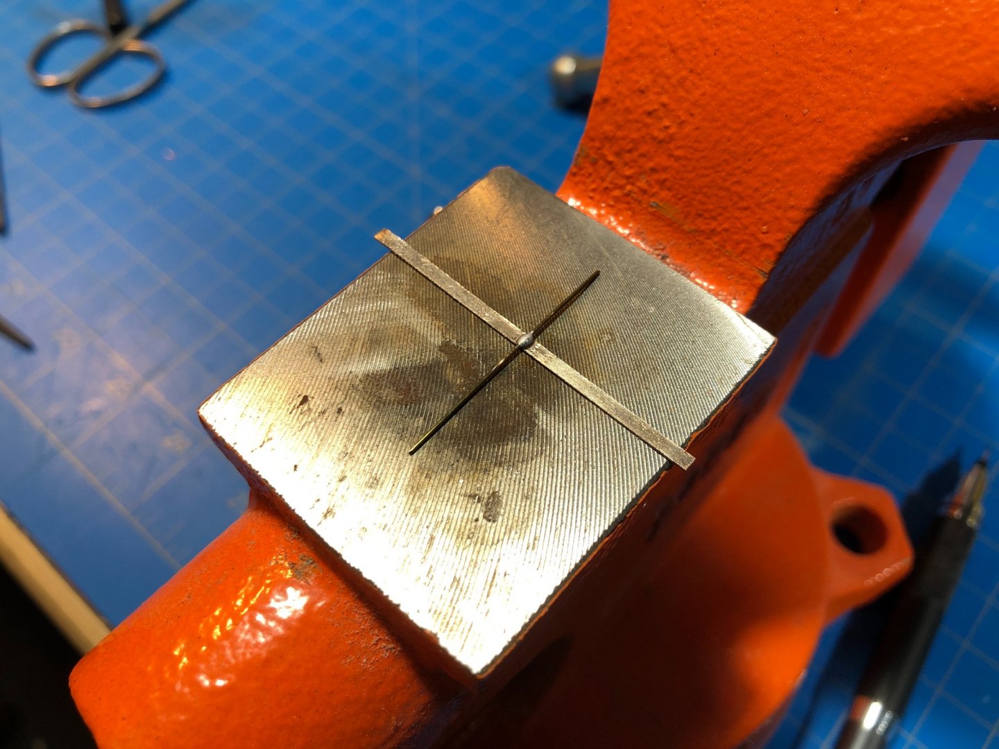
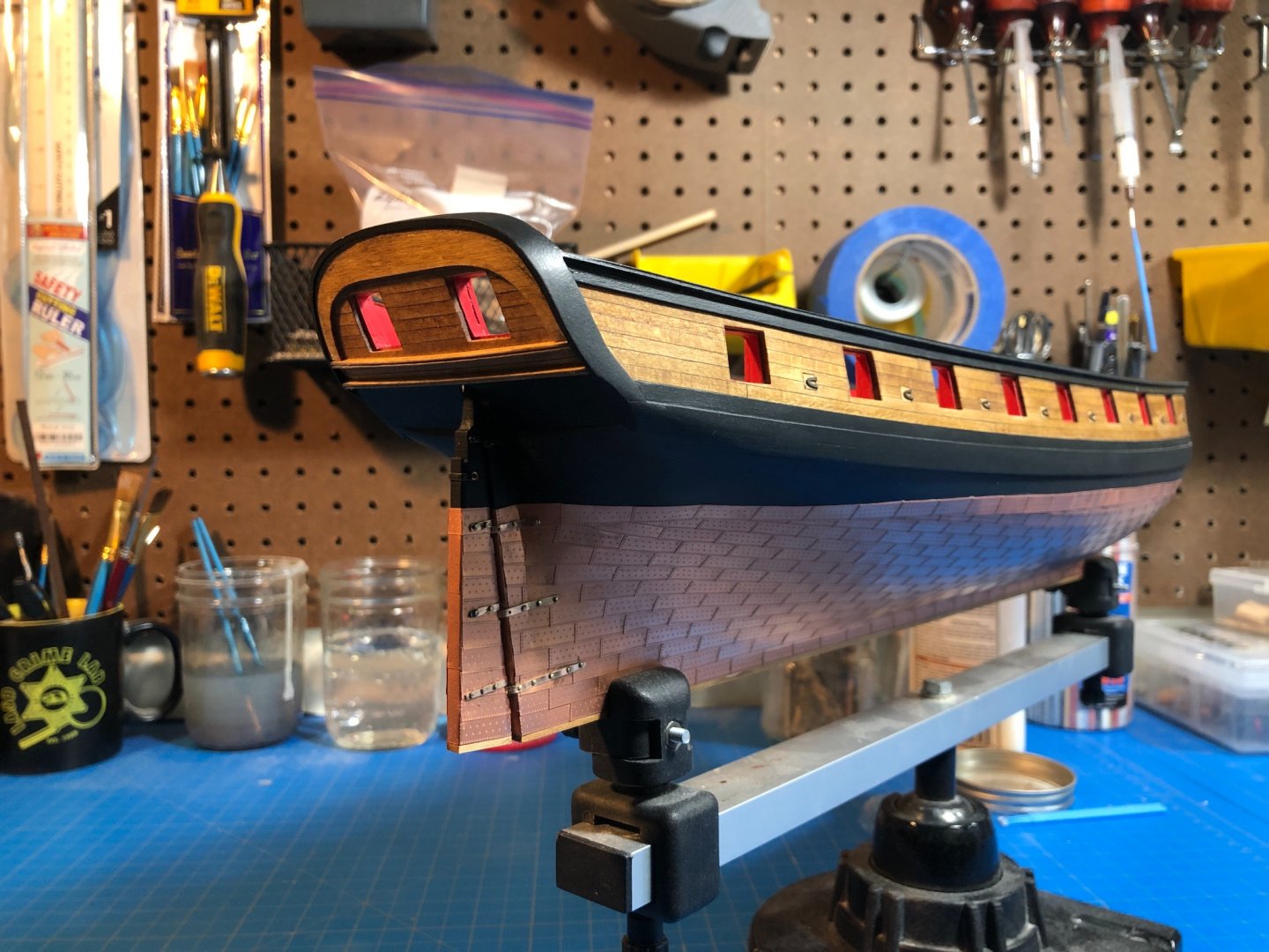
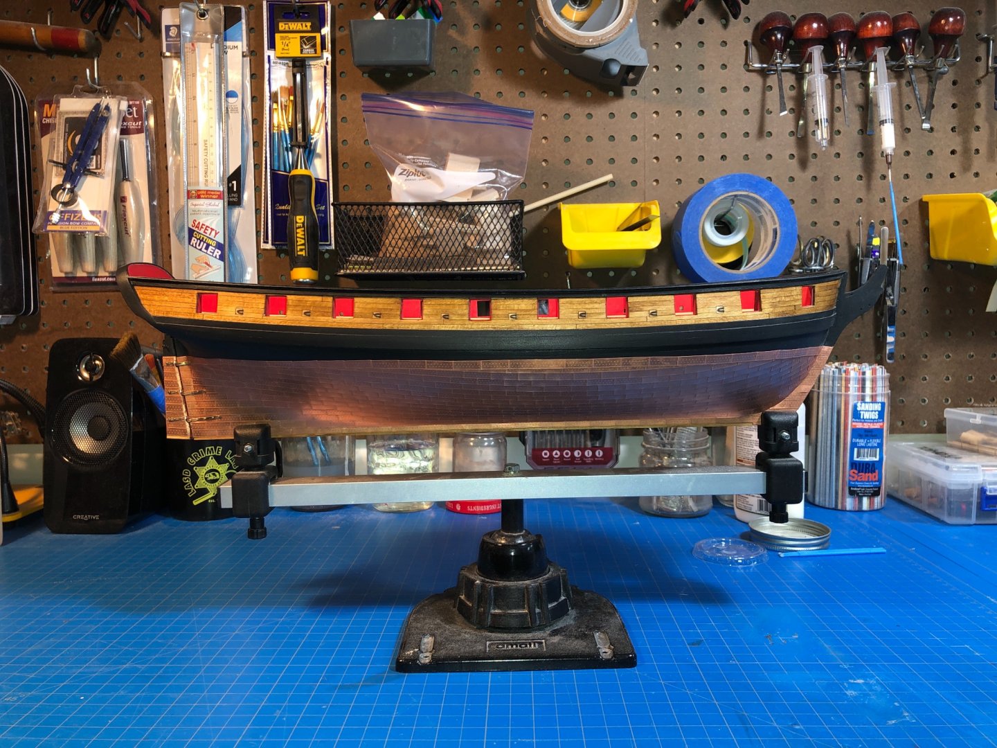
Rudder, Pintels and Gudgeons... A decent break, and nice bit of time to step away from this did the trick. I had been gearing for this bit of the build for awhile. I had decided on bronze for my lintels and gudgeons rather than the copper plated as the available options for achieving this just didn't sit right with me and I recall reading somewhere that bronze was used due to its relative compatibility with copper under the waterline. Having not worked with this material in past, I also wanted to give it a try. I sourced some 28 gauge sheet from Rio Grande at a decent price and used Patricks technique for taking it down to strips by sandwiching it between sheets of some scrap I had laying around. I was especially thankful to have recalled Patricks early discussion about this as it turns out Bronze has quite different workability and does not easily cut by hand as brass does. I had first tried just to cut it with a ruler and razor but that just didn't work at all. This method used on a power saw worked great and was very accurate. After soldering a brass wire for the pintels, filing everything down and blackening the above-waterline components I ended up with a pretty good set of hardware for the rudder. Getting everything mounted properly certainly was not a pretty affair, but it cleaned up ok. The bronze ended up with more scratches on its finish than I would have liked when it was all said and done so I need to sort out some kind of polishing situation at some point. Trying to do this after the fact is not ideal, but I think I got some tunnel vision and didn't really notice how much it was scratched up until examining it again the next day. Overall though, I really like the contrast of the bronze/copper and especially like that its not brass and I avoided trying to make the copper tape work which I think would not have worked given the finish of the Amati plates.


-
Fantastic and again, great photography! What are you using?
- 950 replies
-
- 1
-
-
- syren
- model shipways
- (and 1 more)
-
Hey Mark, thanks for dropping in and thank you very much for helping me with all the questions I had getting started.
-
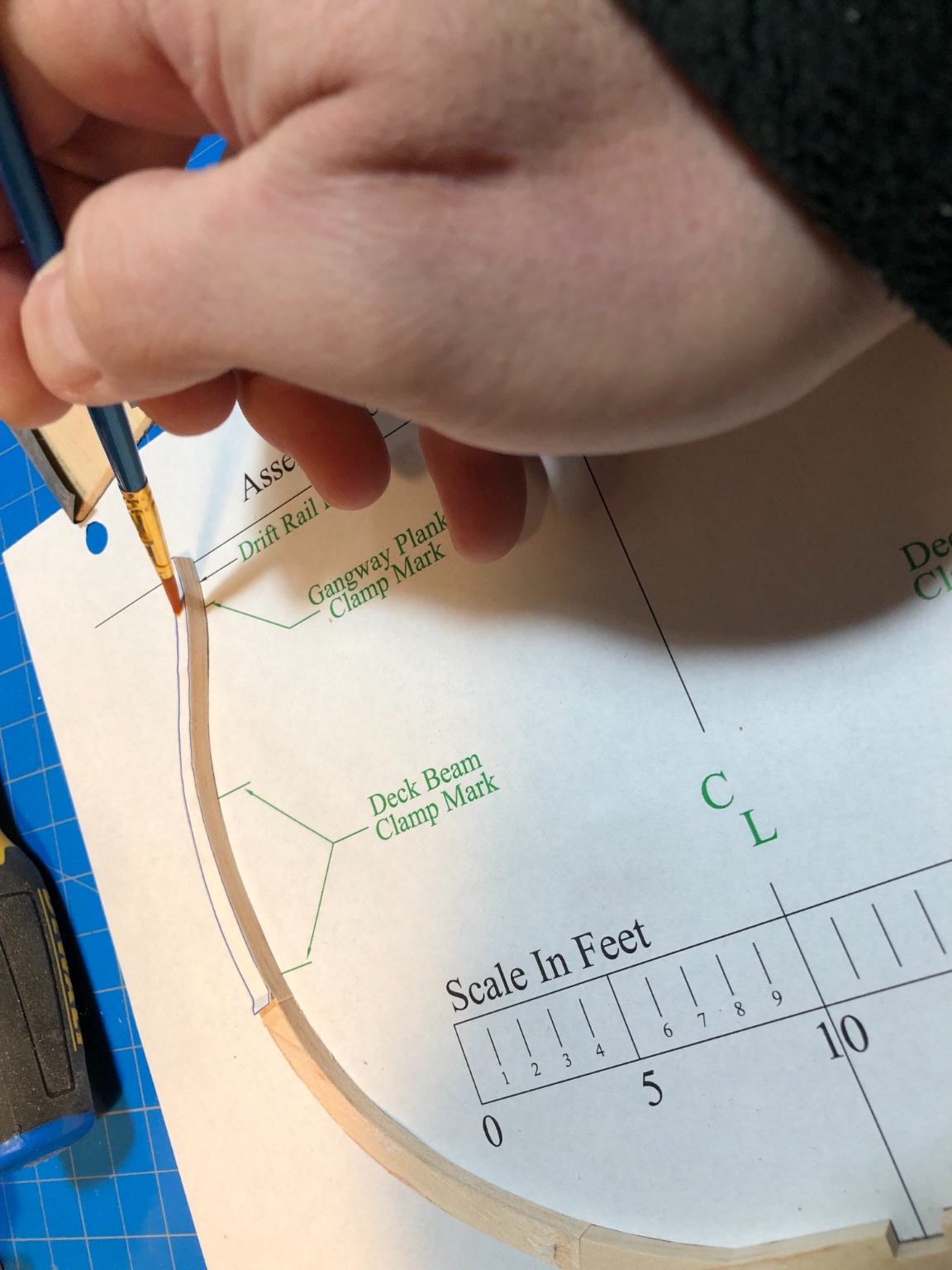
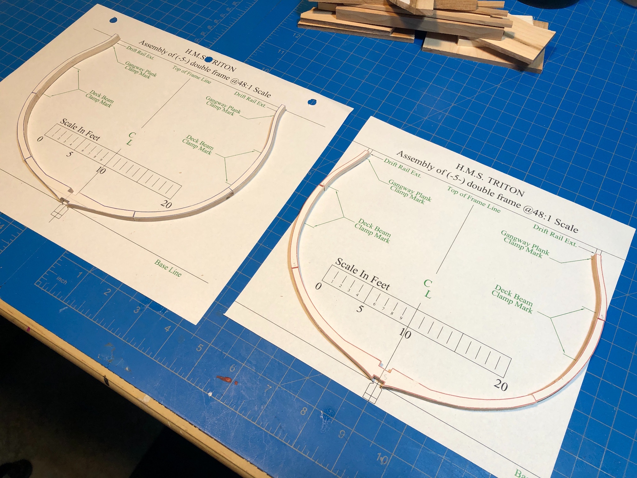
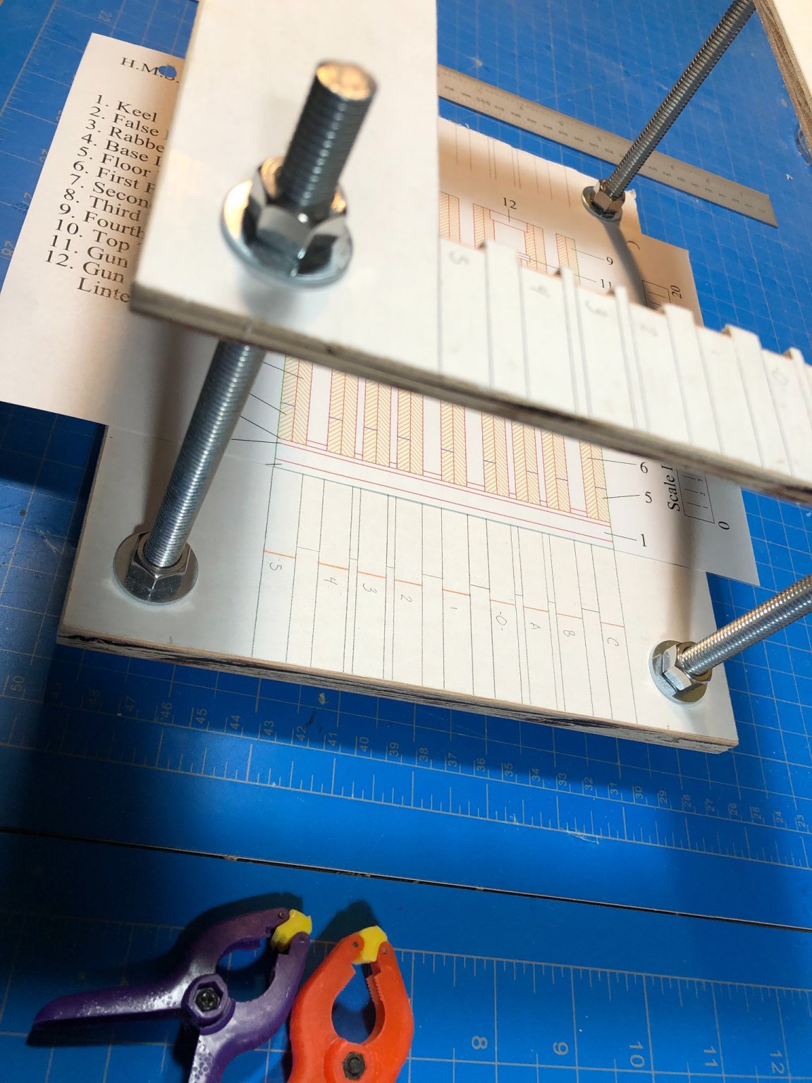
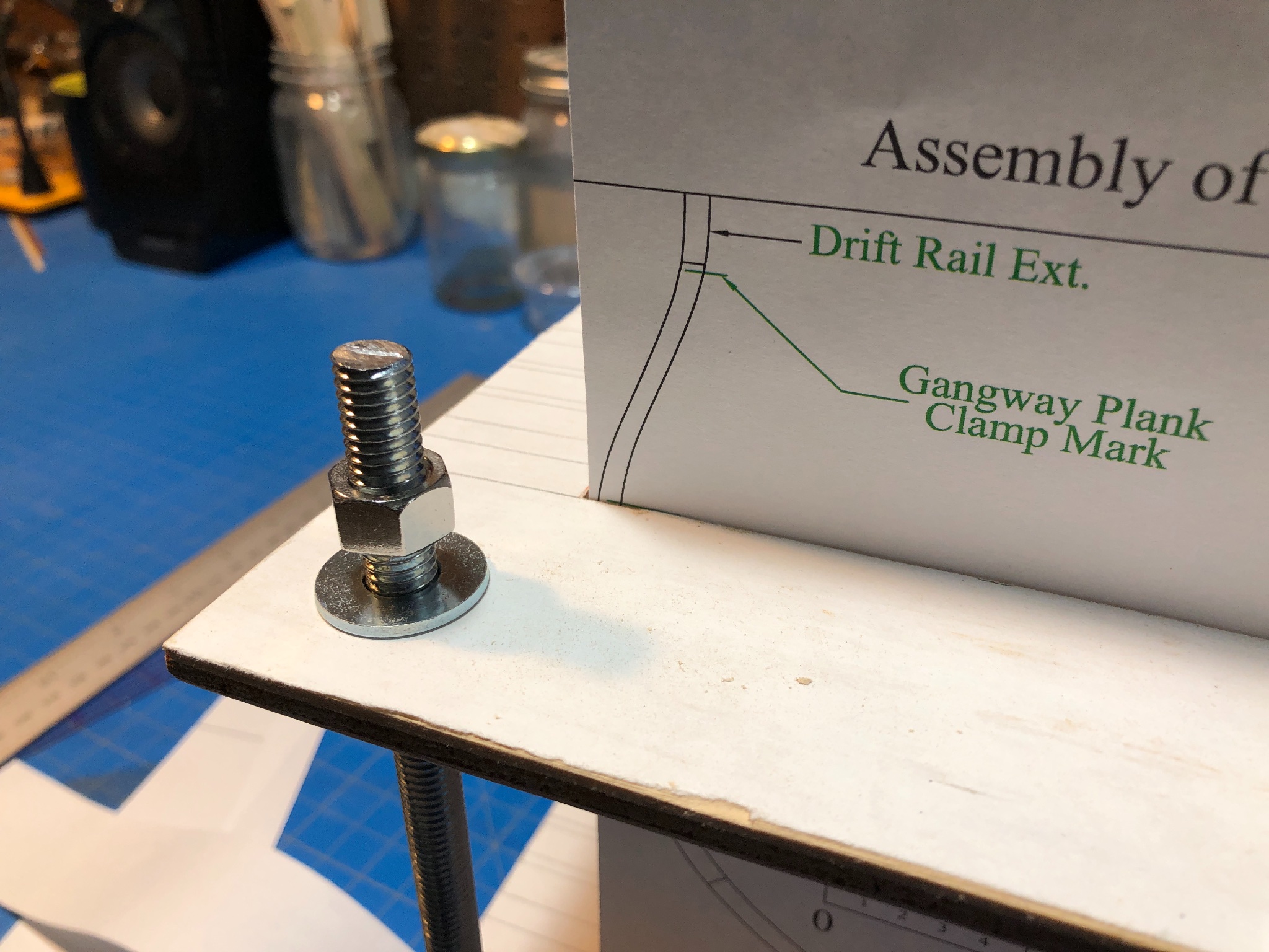
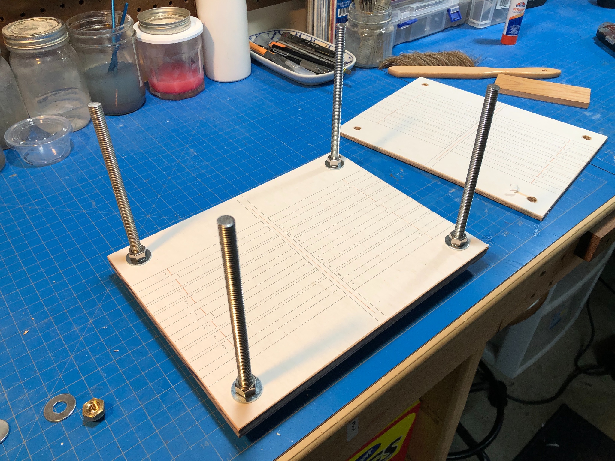
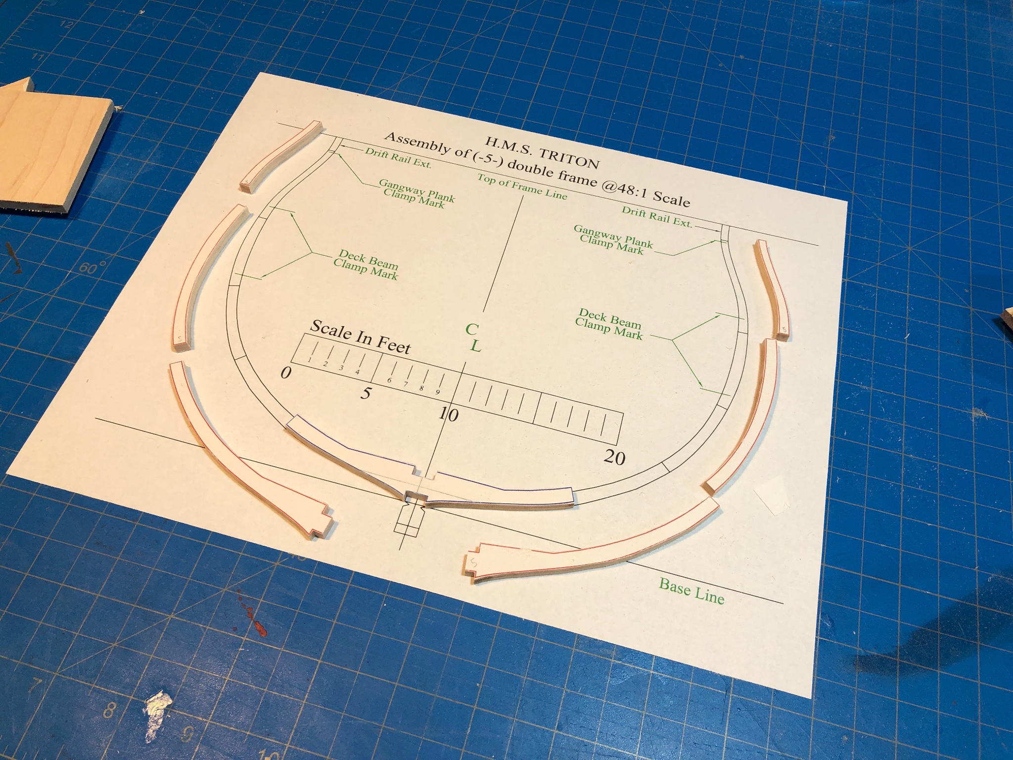
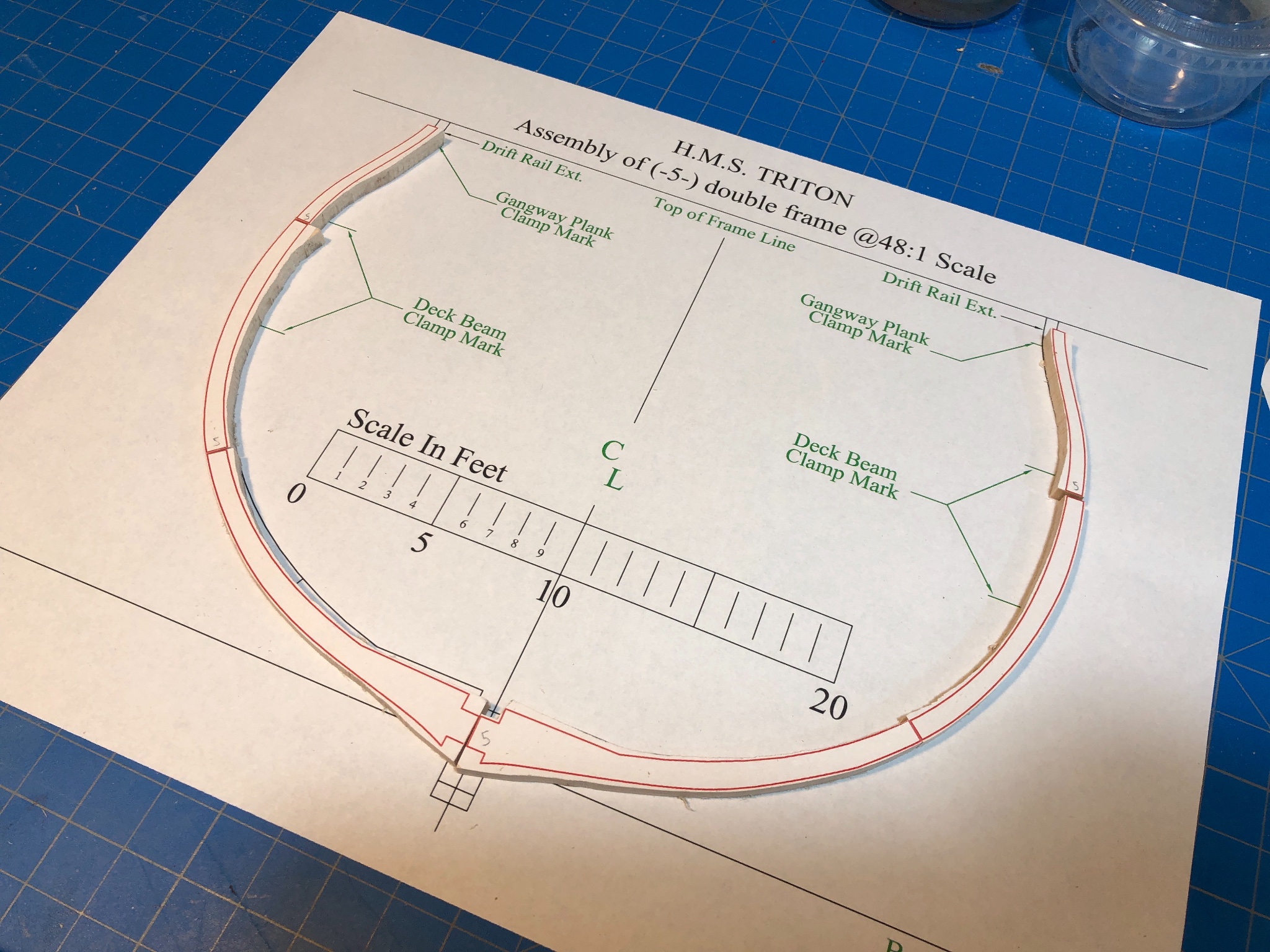
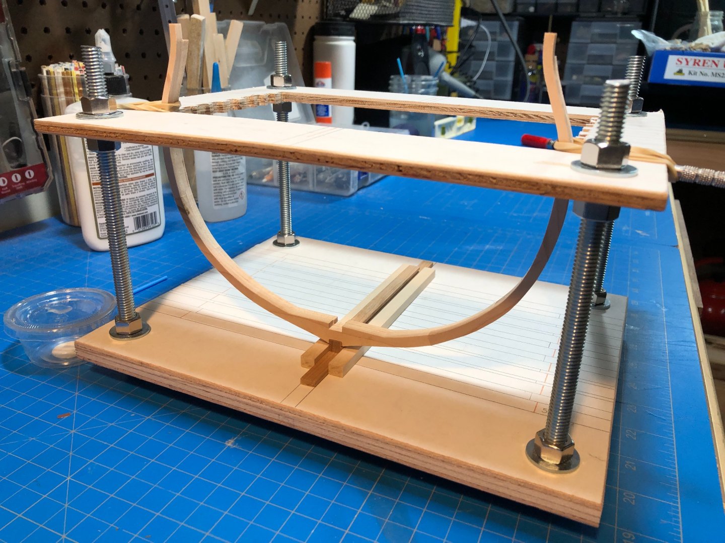
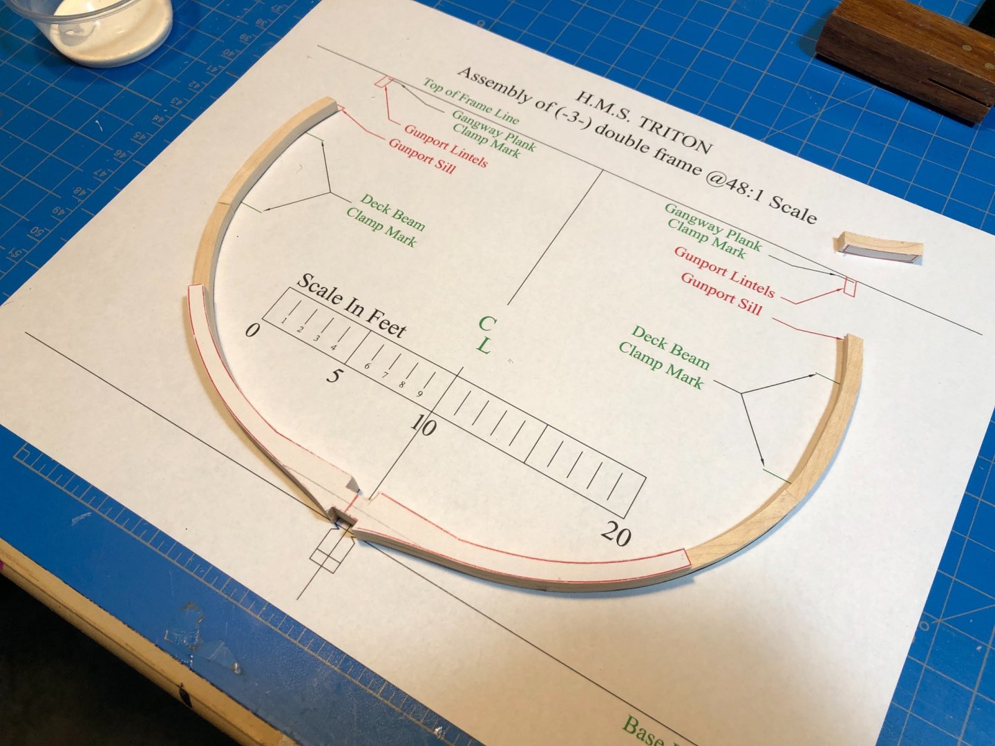
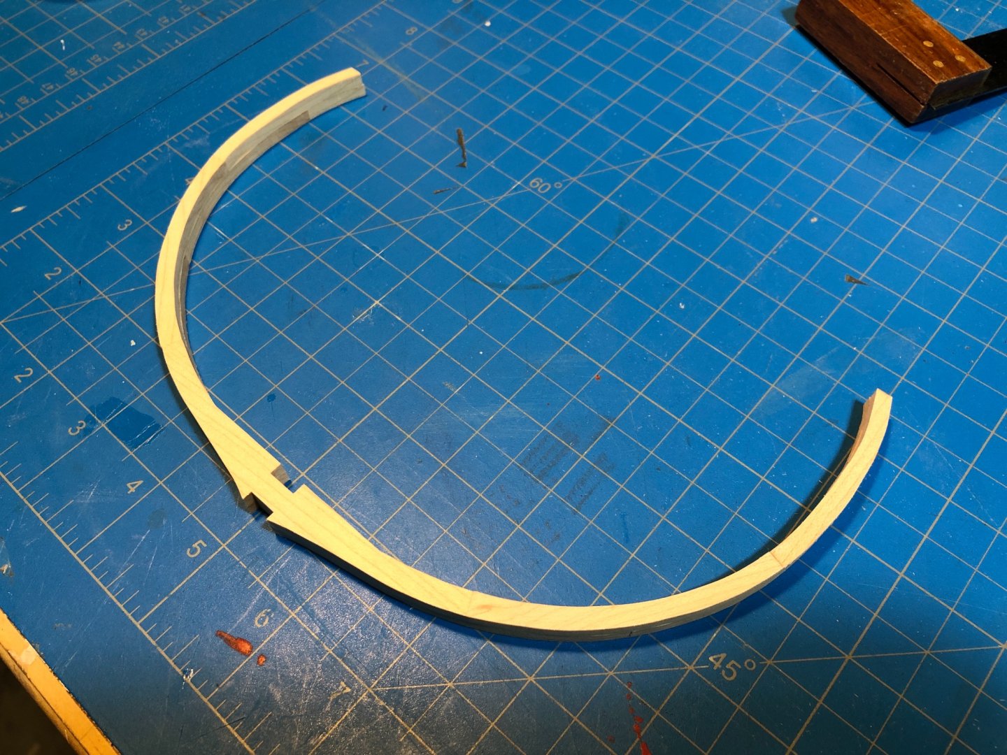
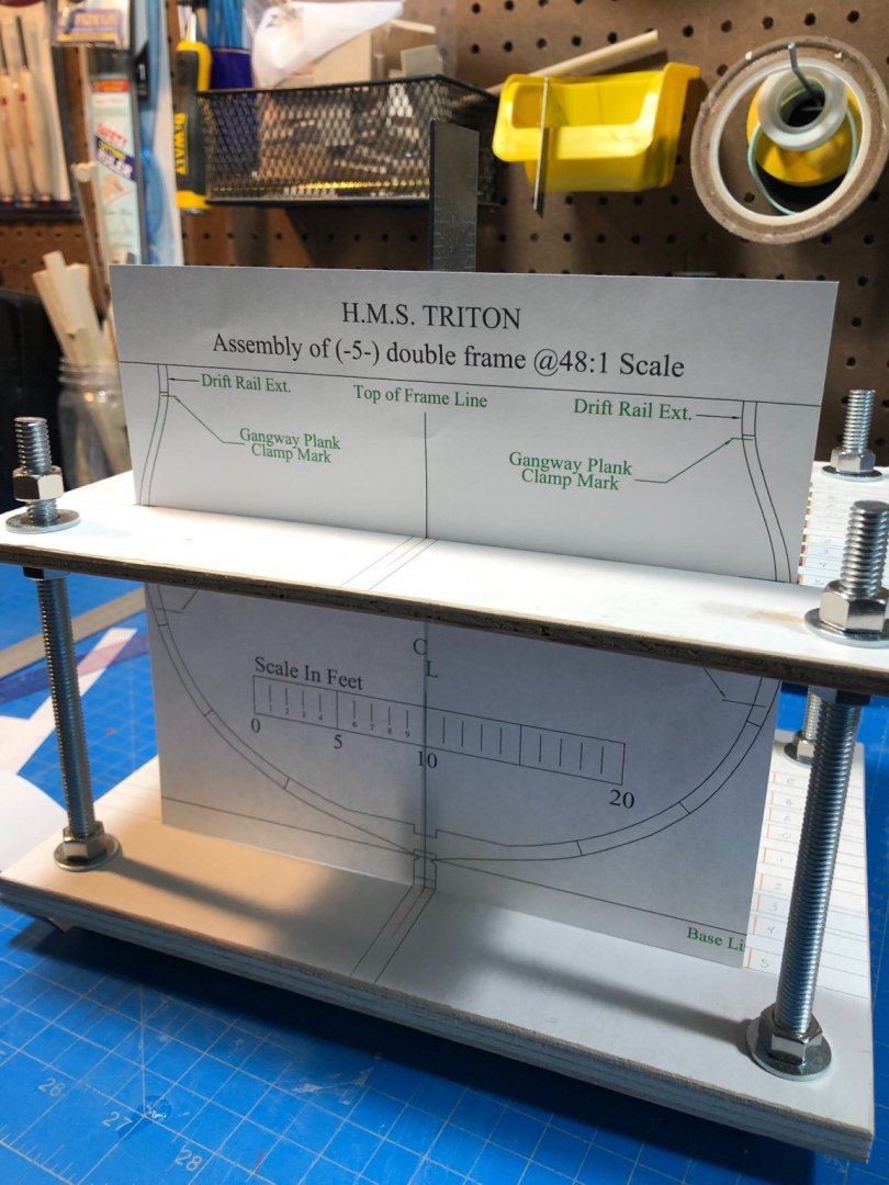
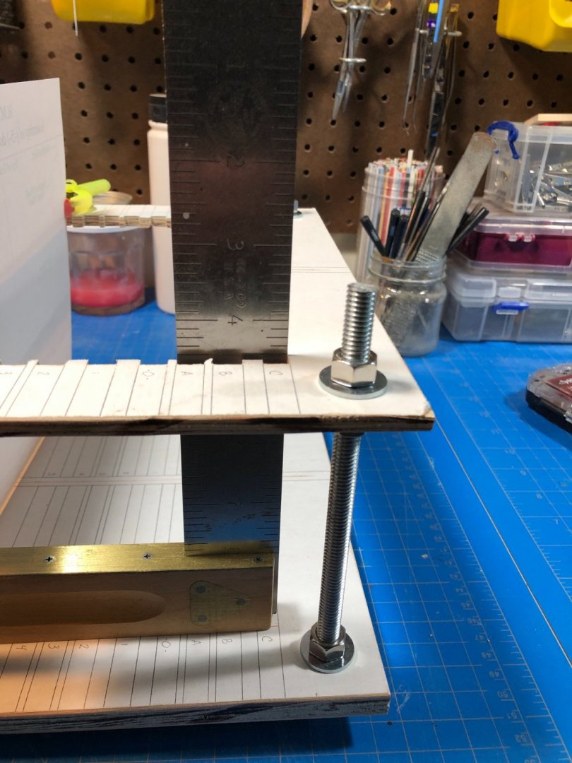
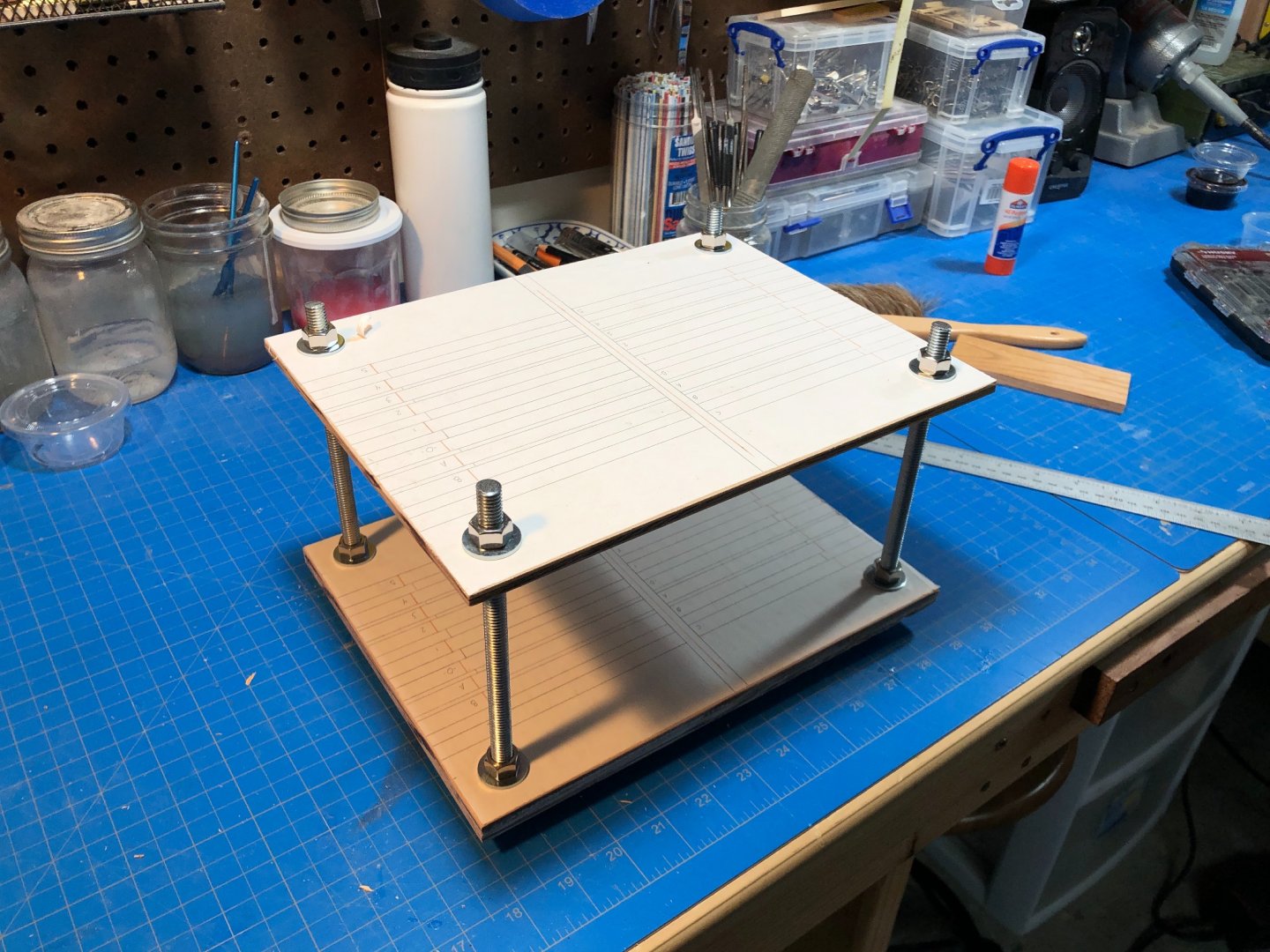
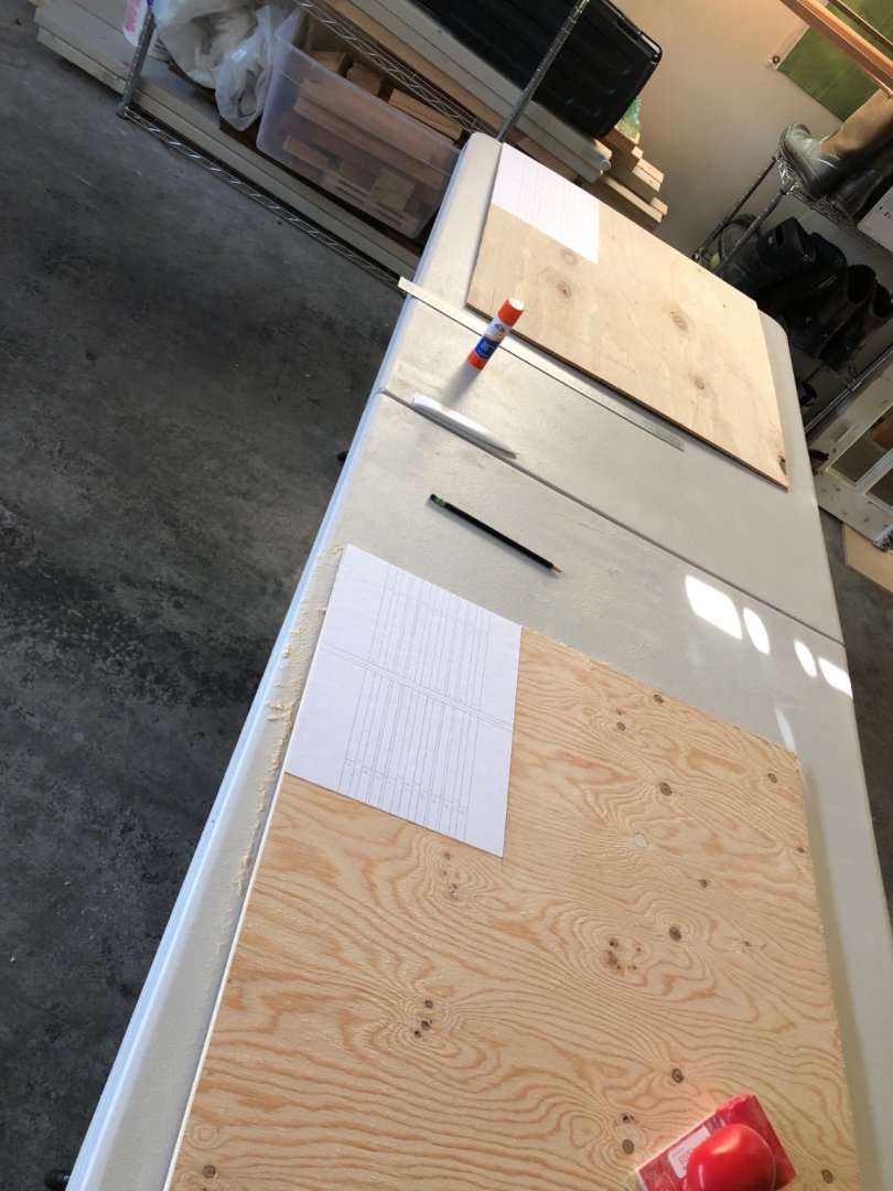
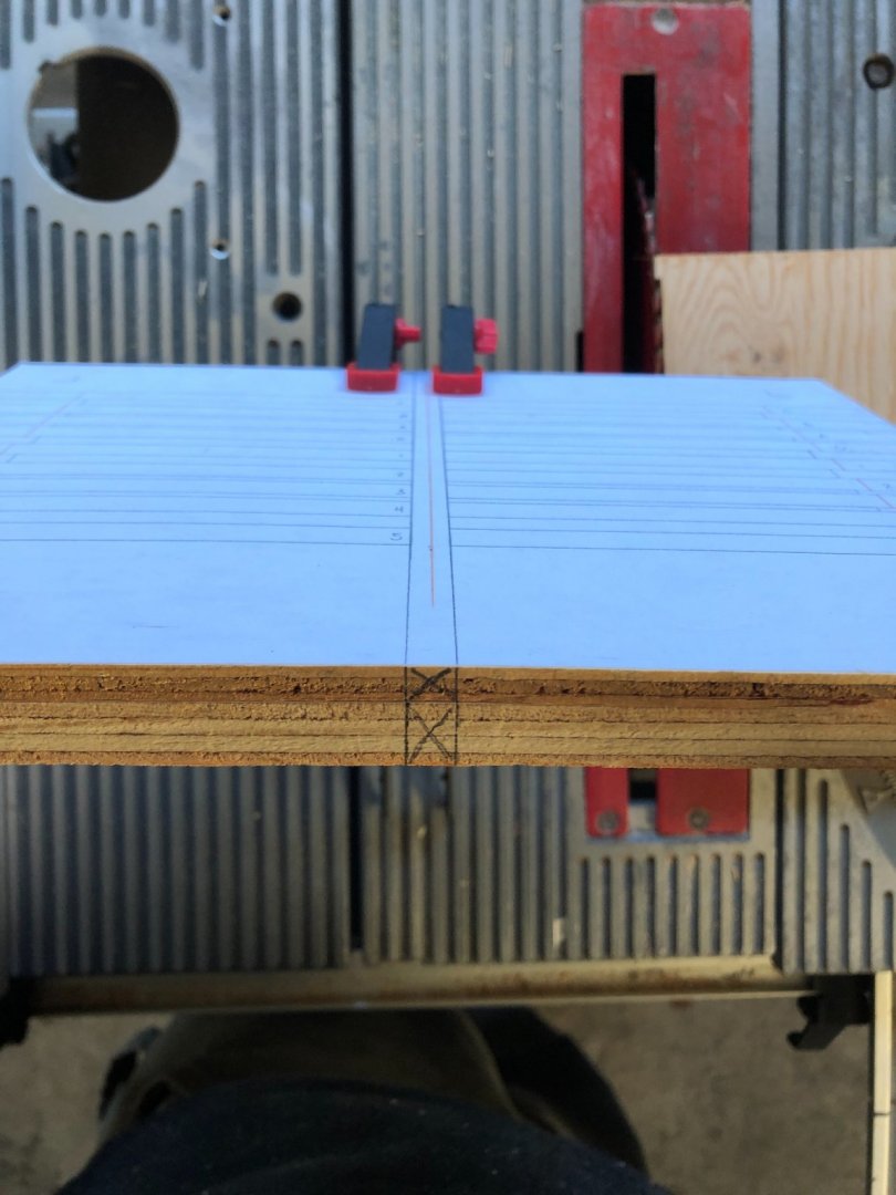
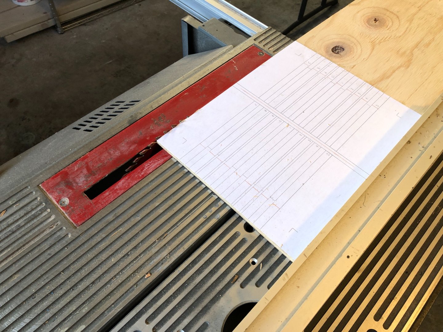
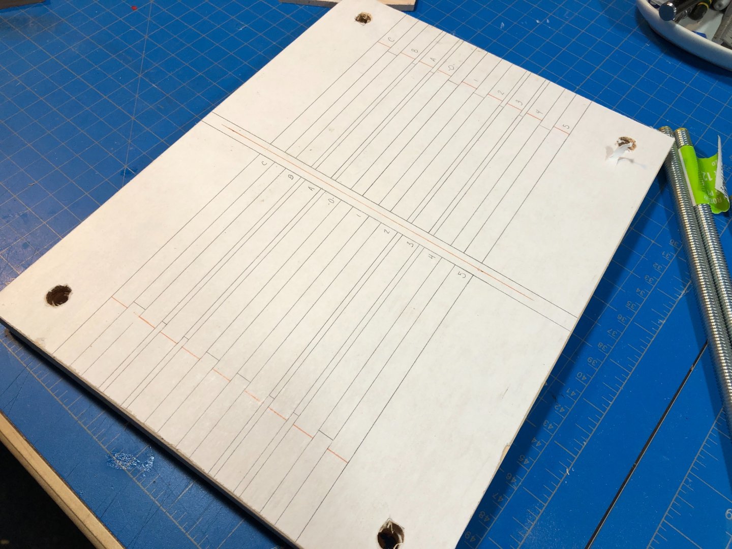
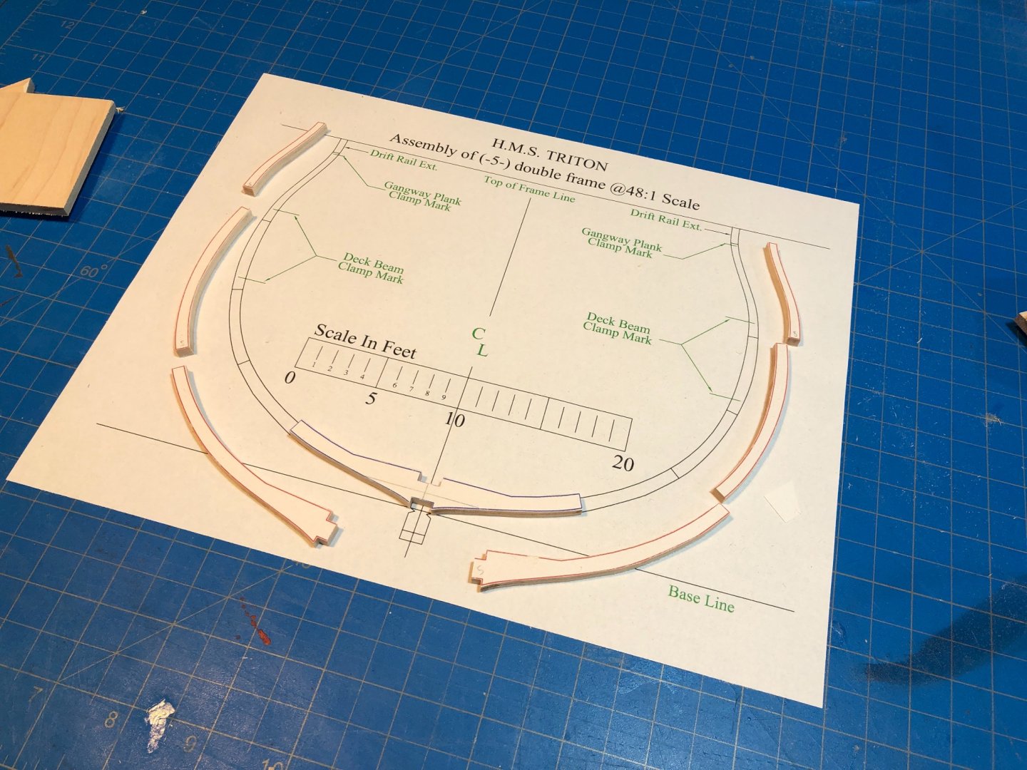
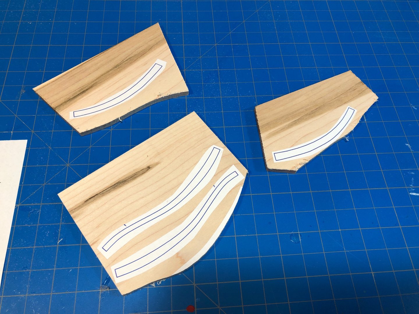
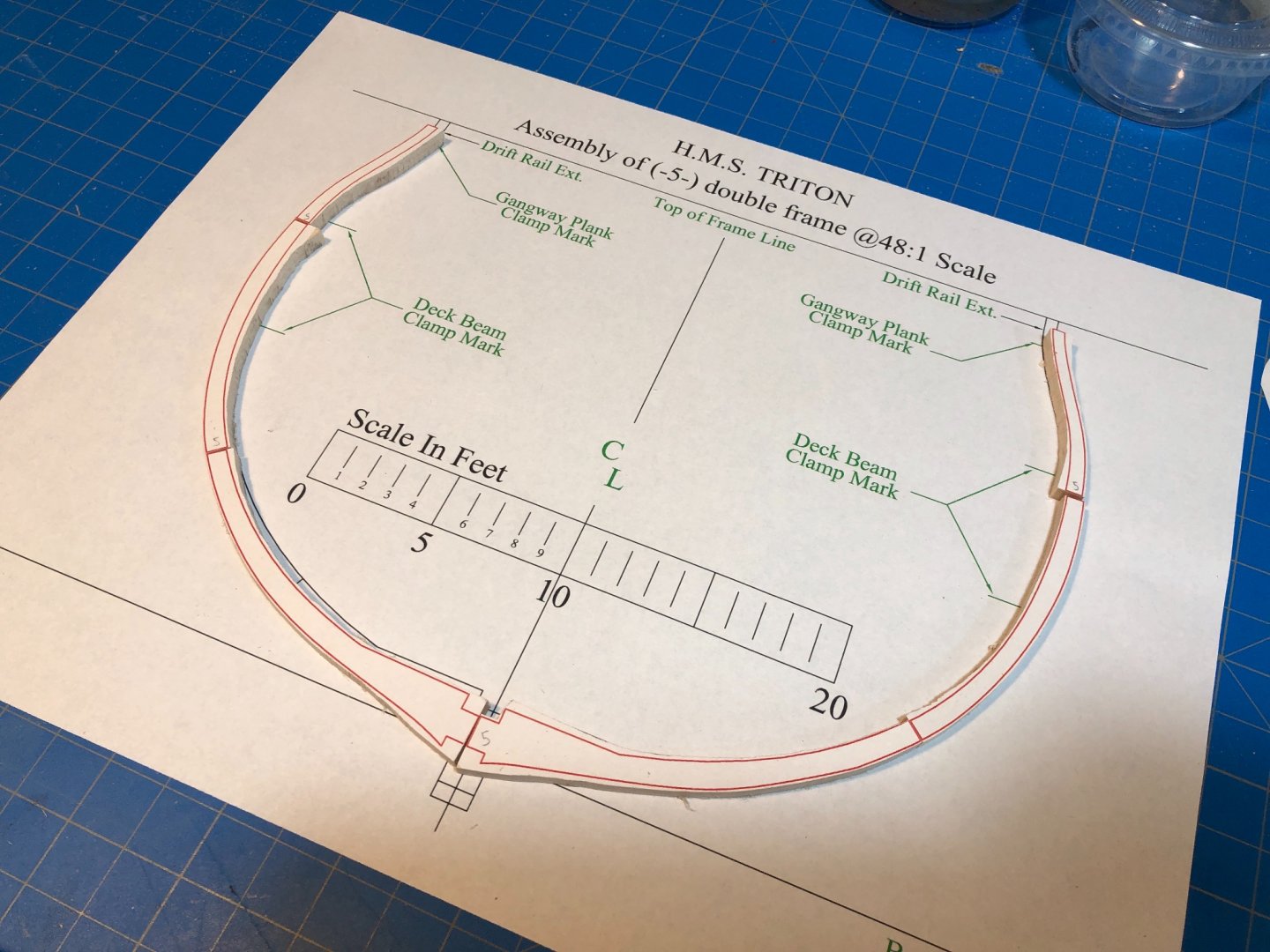
Building Jig. In the last few days I set about creating a building jig similar to other previous builders. I had thought there might be an available cross section Jig plan in the Triton downloads section as there is one for the full POF Triton build, but came up short. I experimented with trying to cut down a full size jig plan to create a cross section plan, but discovered there are a number of differences between the full build and the cross section, despite being both 1:48 scale sets of drawings. In the end I created my drawing as Im sure others have done, and went to work. If anyone would like to use my drawing for their own work, I'll attach it here. If printed at 100% on standard letter copy paper it should be accurate. Be careful to check the lines against those of the provided drawings to be sure it is scaled and printed correctly. Triton Jig Plan_1-48_Justin P.pdf Having never done this before, I did sort of invent my own process which may or may not be like how others have approached this. I wound up using a 1/4" rough ply for the top and a 1/2" rough ply for bottom. I bought a sheet of 2' x 2' of each and sanded an area marked out exactly to the dimensions of the printed drawing (8.5 x 11" copy paper). I used a plain Elmers glue stick to apply the sheets. In order to really prevent the paper deforming at this scale you really need to glue out the ply instead of the sheet - the reverse of what you might do when gluing assembly parts. I had drawn guide lines on the ply to help with laying down the sheet of paper and help ensure that I have properly glued the entire area. Using my full-size table saw I then ripped down the two sheets of ply along the edge of the copy paper. This gave me two sheets exactly 8.5 x 11" with a duplicate and well-aligned drawing mounted to each. I then drew in registration marks to each board edge marking the keel and the center frame. This was important as there was a 1-2mm of difference in the alignment, so by using the registration marks I could clamp them together just right and drill the post holes so that when assembled all the lines would be true and aligned to one another top to bottom. I drilled those holes at exactly 3/8" and used 8" x 3/8" all-thread for the posts. This provided a very secure fit, and along with the washers and nuts created a very rigid structure. I used a jig saw to cut out the meat of the top board interior and then a coping saw and files to finish the cut. I then used a combination of squares and the provided drawings to make all the necessary checks. I had set this drawing up so the the distance between the top of the bottom board and top of the top board came out to exactly the distance between the floor of the keel and the upper Deck Beam Clamp mark. Incidentally, this turns out to be roughly the same as the indicated height for the full POF jig plan. After that I positioned the keel in a jig mounted to the bottom board. The jig itself is complete and ready for frames. As for frames, Im still working out all the steps of my process. Trial and error, but Im close. My drill press/drum sander setup is finally put together and is working well. I had intended on using a 2" diameter drum but had trouble getting it to center properly causing it to wobble intolerabely. The 1" drum works perfectly though. Ive gotten all the components of my first "test" frame cut out and ready for a final fitting at the joints. This step is hand work, so will proceed much more slowly to get it right. Hard to know what the tolerances are and how falling on either side of those tolerances will effect the end result... Right: Fresh off band saw, ready for sanding. Left: After sanding on the drum. Two halves of a single frame ready for final assembly.


-
Thanks! I thought about this a long time and considered the coping saw. I even went so far as to have a go trying to cut out a frame piece and I just didn't have the patience for it, and the considering the time requirement for each and my own limited time in the shipyard I figured a power tool was the way to go for me - and if Im honest, I also wanted a reason to buy a new tool or two ;).
-
Very clean! I wish mine came out like that. Seems like no matter how hard I try I can never get my cuts or joins that clean! You've got it!
-
I totally agree, the transom took me ages to get through and even then when I thought I had finished I would come back to it another day and decide I needed to work on it some more. At one point I tore bits off and redid them. Progress is slow, but the wait is worth it!
-
That bow rigging is really bring the thing together, and your execution is fantastic. Are you using any supplemental reference materials or going by the plans and kit provided stuff only? Those masts look great too!
- 950 replies
-
- 1
-
-
- syren
- model shipways
- (and 1 more)
-
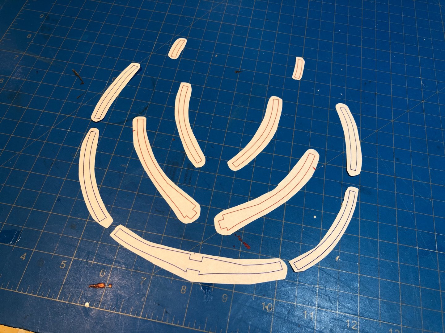
Frame Tests So today I took a crack at cutting some frame components. I am learning a lot... namely, that I need to practice a lot. I fixed the templates to the sheet with an Elmers glue stick to avoid deforming the paper and it seemed the more more easily reversible of the various options. Im trying to fit the pieces between the grain with a mind towards paying careful attention to the most fore and aft frame faces in particular. At the moment Im really just viewing this first frame assembly as a practice piece, and to work out a process and decide how I want the various tools I intend to use set up. I tested a few approaches and ultimately think the band saw was the right choice. I was able to cut within about 1-2 mm without much trouble and only had two sacrifices to the bone pile. The first set came out a little rough, but as I went I got much better. When I really nail down a process that seems more repeatable and less experimental, Ill be sure to detail it here.
-
Actually no. Im not doing any resawing at all. The Ryobi couldn't handle that type of work unless resawing very small billets. I ordered all my wood pre-milled to the thickness required by the parts laid-out in the Triton plans. There are a few parts, like the Keel and others that are stipulated at a thickness that Ocooch does not provide and so the Byrnes was required to take it down. The band-saw is for cutting out the keel parts from sheet stock. For example, a single side of a frame is 3/16" making the assembled frame a full 3/8" when complete. Therefore I ordered 4" x 24" x 3/16" Maple sheets to cut them from, make sense? See here: https://ocoochhardwoods.com/scroll-saw-lumber/ As I said in my first post, ChadB did a lot of the work going through and making a list of required dimensions, I made some species substitutions, verified the required thicknesses from the plans and ordered all the wood pre-milled. There will be minimal re-thicknessing required on my end. Most of the work will be on my Byrnes table saw and the new band saw. The drill press was added to make final sanding of the frame parts easier using a drum sander attachment (total for both < $200) and because I just wanted a drill press.
-
Indeed! I agonized over this bit for a while. I have a scroll saw that Ive never really liked using, and did a number of trial runs before ultimately deciding to go the band saw route. After trying out cutting the frames on a friends saw, I decided the band saw was definitely something I wanted for this build. I didn't invest a lot and picked up a Ryobi 9" bench-top model for about $150. Many people gripe about the quality of this level of saw, but I found that if you spend enough time learning how to properly set one up and investing in a good blade for the right purpose then a cheap band-saw can be a really good tool. The subtle scroll work required by the frames for this build is easily handled by the Ryobi, and seems to cut through the 3/16" Maple like butter. If you do end up with a bandsaw, I recommend "Band Saw Clinic by Alex Snodgrass", lauded by many as the best instructional video (on You Tube) for setting up and maintaining even the cheapest bandsaws. While the Snodgrass doesn't speak about the smaller saws, the information is just as applicable. For ordering wood, I found that lowering my standards and learning to love the more available hardwoods alleviated a lot of my anxiety Thanks for joining up early! I hope I can contribute something of value that isn't already well covered by the builders who've come before me!
-
I was recently working on the rudder, and just couldn't get behind it. I think Im getting a bit saturated on this build and need a break. Not from modeling, but perhaps from the type of modeling demanded by Syren. Ive been wanting to dip my toe into more scratch building as well, and have a project that can fit the weird time I have to model when I don't have the focus and stretches of time required by the Syren project in the coming steps. Im also waiting on some bronze sheet that will take some time, and I hate idleness. Im also not the type that can jump ahead effectively and still keep track of what Im doing. I can multitask-task several projects but have never been good at seeing projects through in a non-linear fashion. Ive been preparing for a crack at the Triton cross section group project featured elsewhere on MSW, and have created a build log to record my efforts there. Perhaps some of the skills developed as a scratch builder will benefit me as I approach the more complicated steps coming in this build. To be clear, Im not abandoning this project, just fitting something else in knowing this one may take a quite a long time and want to prevent burn-out. Stay tuned ;), rudder coming soon.
-
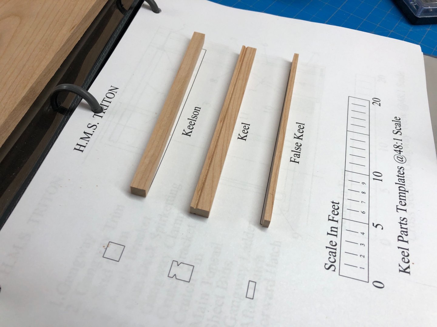
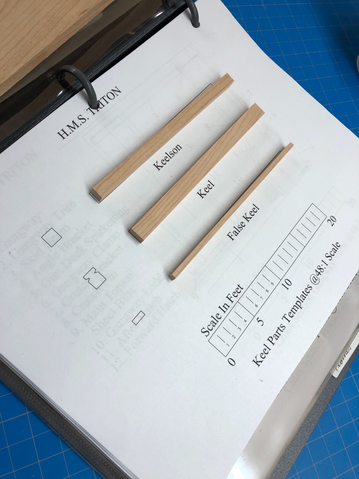
Prep. This will be my first wholly scratch built project. Im undertaking this in addition, and as as a distraction, from my longer-term project HMS Syren by Chuck Passaro and Model Shipways. Ive spent quite a lot of time looking over the various build logs, both more recent and those recovered from pre-crash MSW. I had initially wanted to experiment with the more rare woods, but after getting a sense for their availability and expense, I thought it better to stick to the more common woods for this first attempt. While I would have liked to achieve the contrasts that other builders have achieved using more exotic woods, Im hoping to achieve something similar with some subtle staining. We'll see how successful that turns out. That said, Ill be using primarily Maple for the frames and deck framing and Cherry for the keel and keel components, planking and assorted deck fittings. While some way off right now, Im also hoping to experiment with incorporating Walnut for traditionally darker features and possibly Wenge for the wales. Ive made an initial purchase through Ocooch Hardwoods utilizing the timber plan originally provided by @ChadB from his gorgeous build. Aside from my making some species substitutions, I found his plan to be immeasurably helpful in preparing my order and want to be sure he gets the credit that is due. Reading through the many later Triton builds, I think his contribution has been valuable to others as well. In addition to this other prep, Ive finally added three new titles to my library which have also been mentioned by many in the Triton cohort: Dodds and Moore, "Building the Wooden Fighting Ship" Frolich, "The Art of Ship Modeling" Goodwin, "The Construction and Fitting of the English Man-Of-War, 1650 - 1830" ...as well, I have been intending to finally invest in Antscherl's "The Fully Framed Model" series. Day One. For the first stages of this build, Ive only ordered the Maple and Cherry, in a quantity that should take me through much of the construction phases of the build and with a healthy buffer for mistakes. Ocooch does not supply wood pre-milled to the 5/16" thickness required for the Keel components, so after cutting them out from a sheet of 3/8" Cherry, I took them down with the Byrnes thickness sander. I then took the Keel and milled out the rabbet using my Proxxon MF70 and the appropriate bit. Sadly I was so focused on getting it right, that I neglected to stop and take a picture of this step (UPDATE: Photos added). Luckily, all went well here and Im excited to move on. Im not fooling myself though, I know this step is really nothing compared to the challenge of building the frames and Ive got a lot to think about. The next step is to prepare the building jig, which Im hoping to move onto in the next few days. As this is a concurrent build I suspect progress will be slow, but Im looking forward to it: