HOLIDAY DONATION DRIVE - SUPPORT MSW - DO YOUR PART TO KEEP THIS GREAT FORUM GOING! (Only 36 donations so far out of 49,000 members - C'mon guys!)
×

Justin P.
-
Posts
1,008 -
Joined
Content Type
Profiles
Forums
Gallery
Events
Everything posted by Justin P.
-
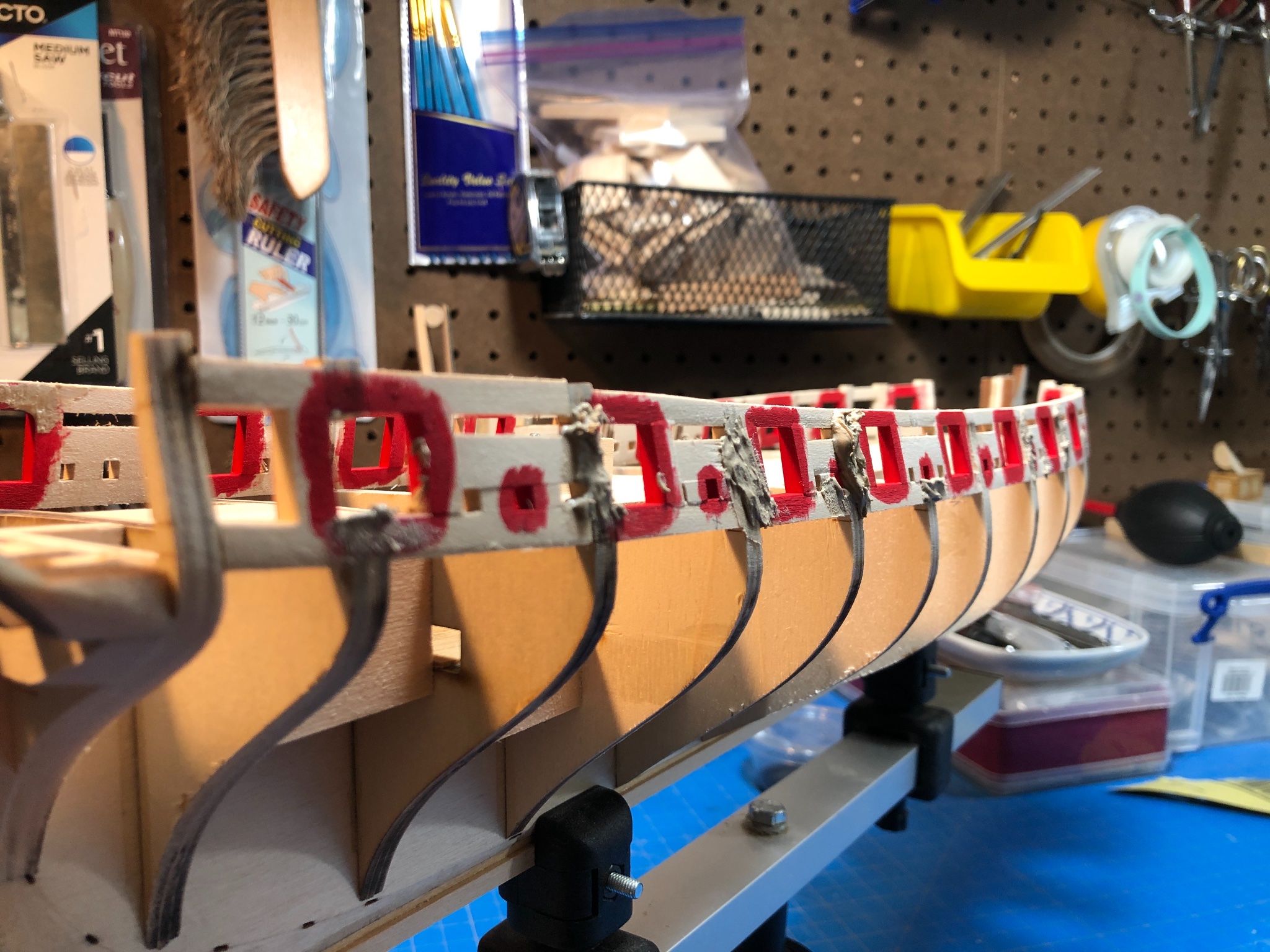
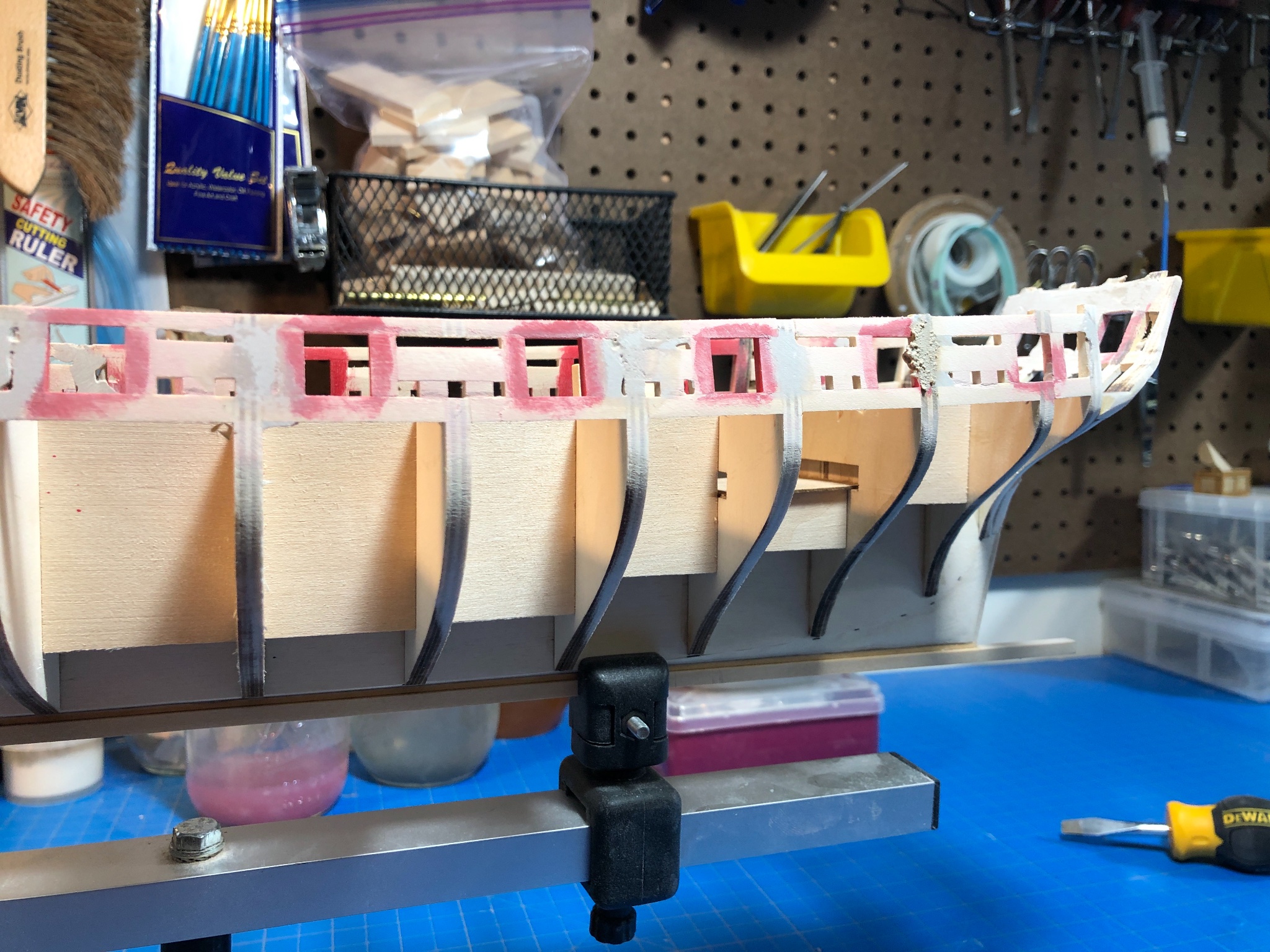
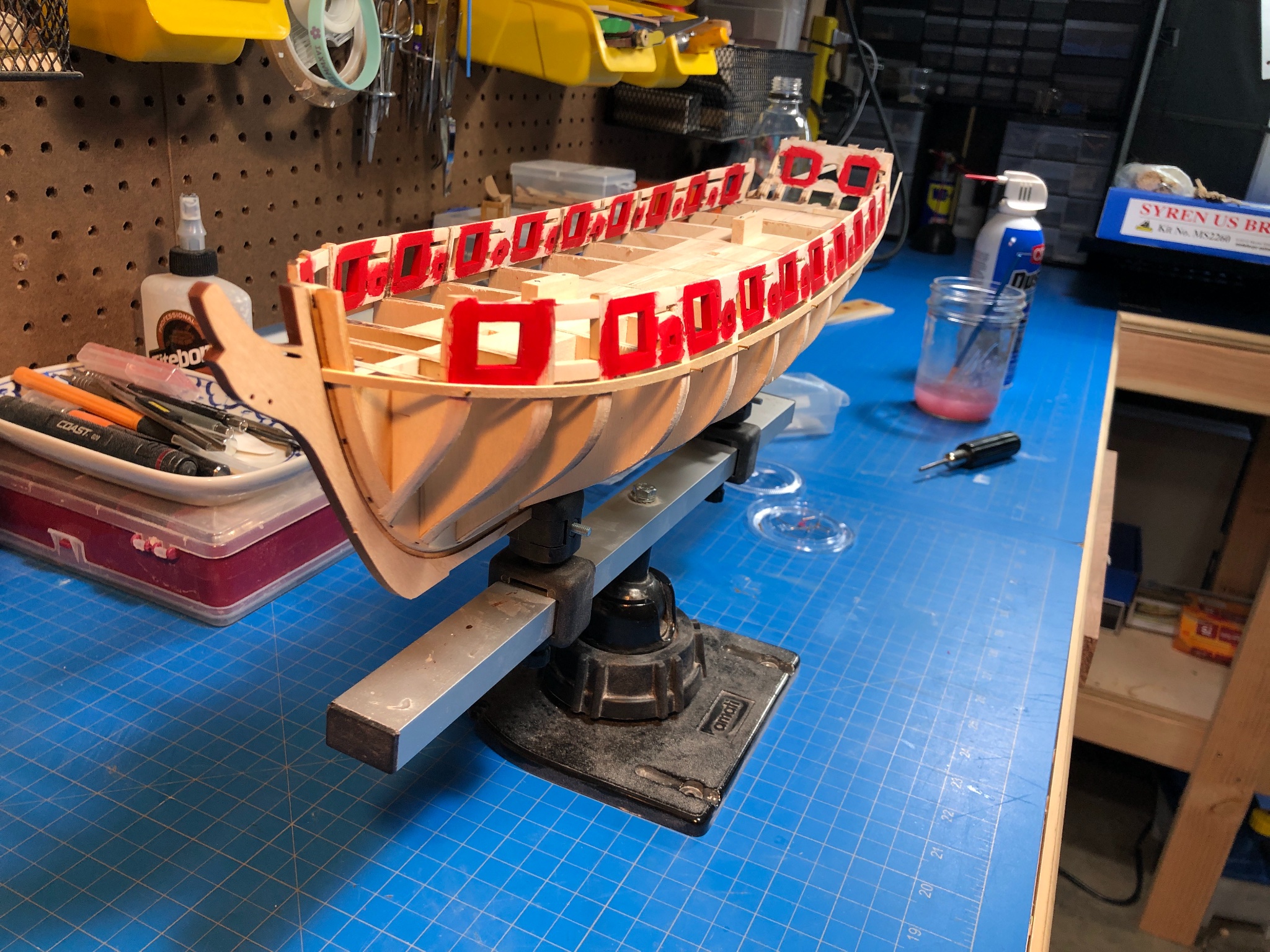
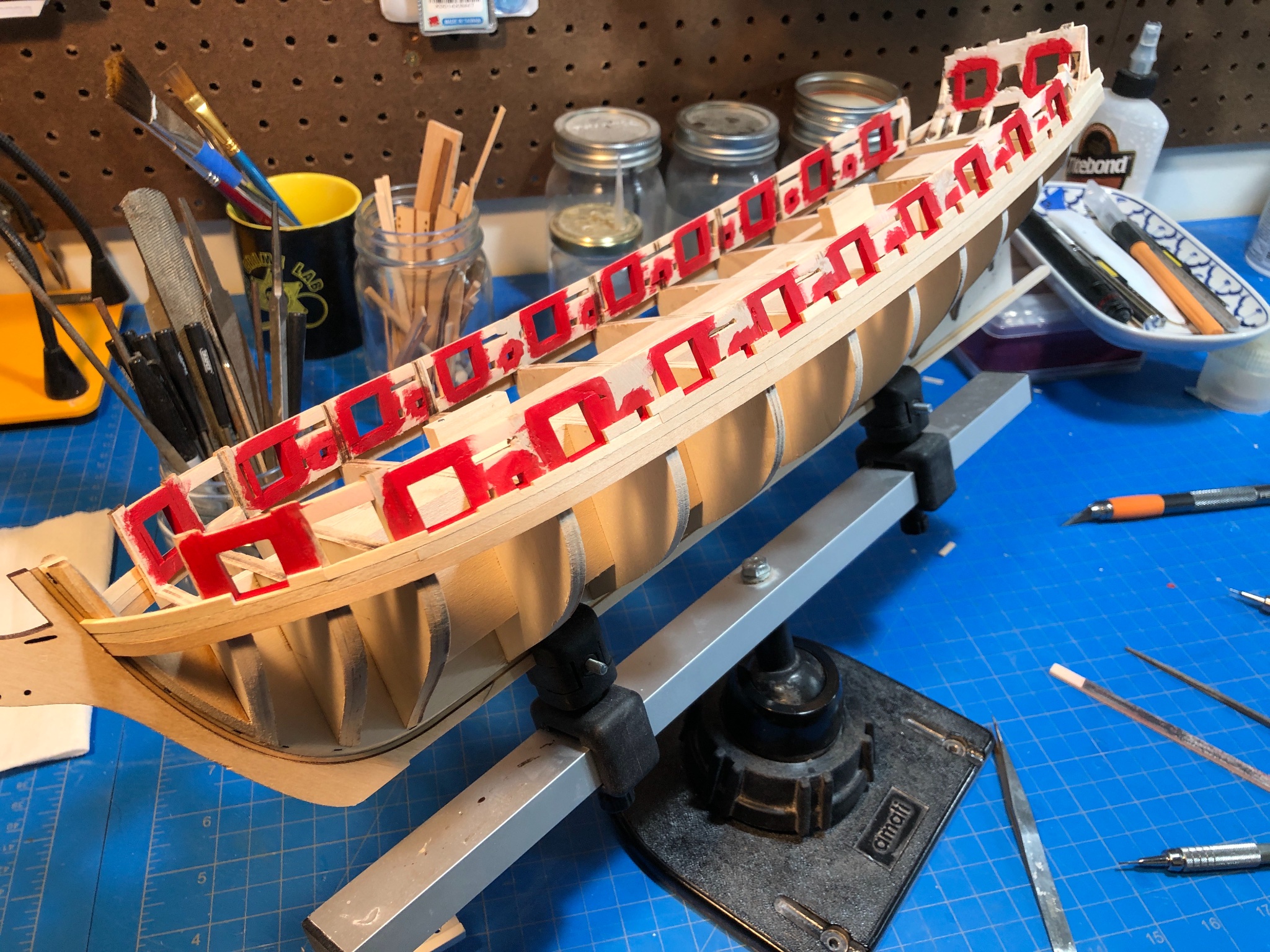
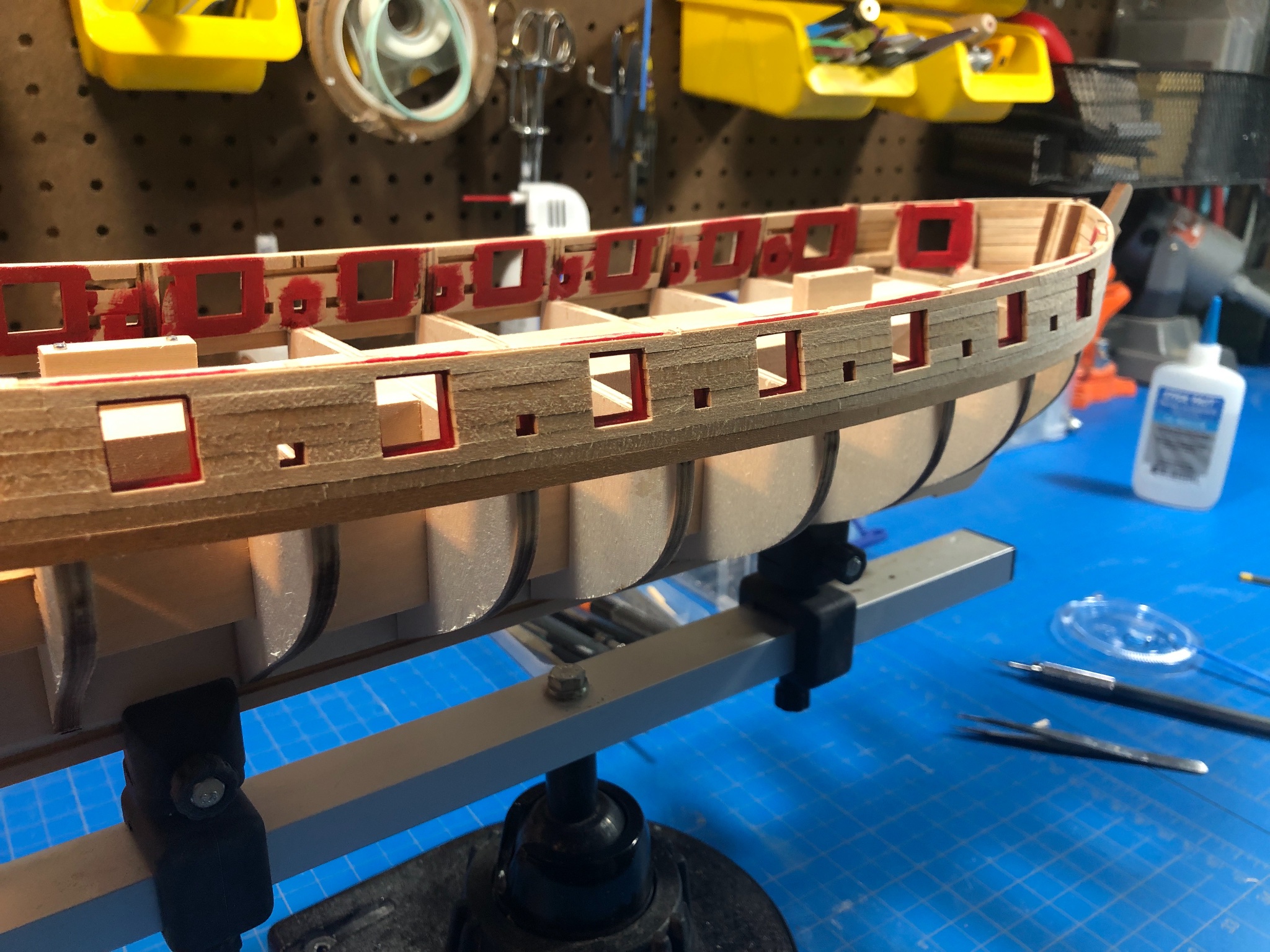
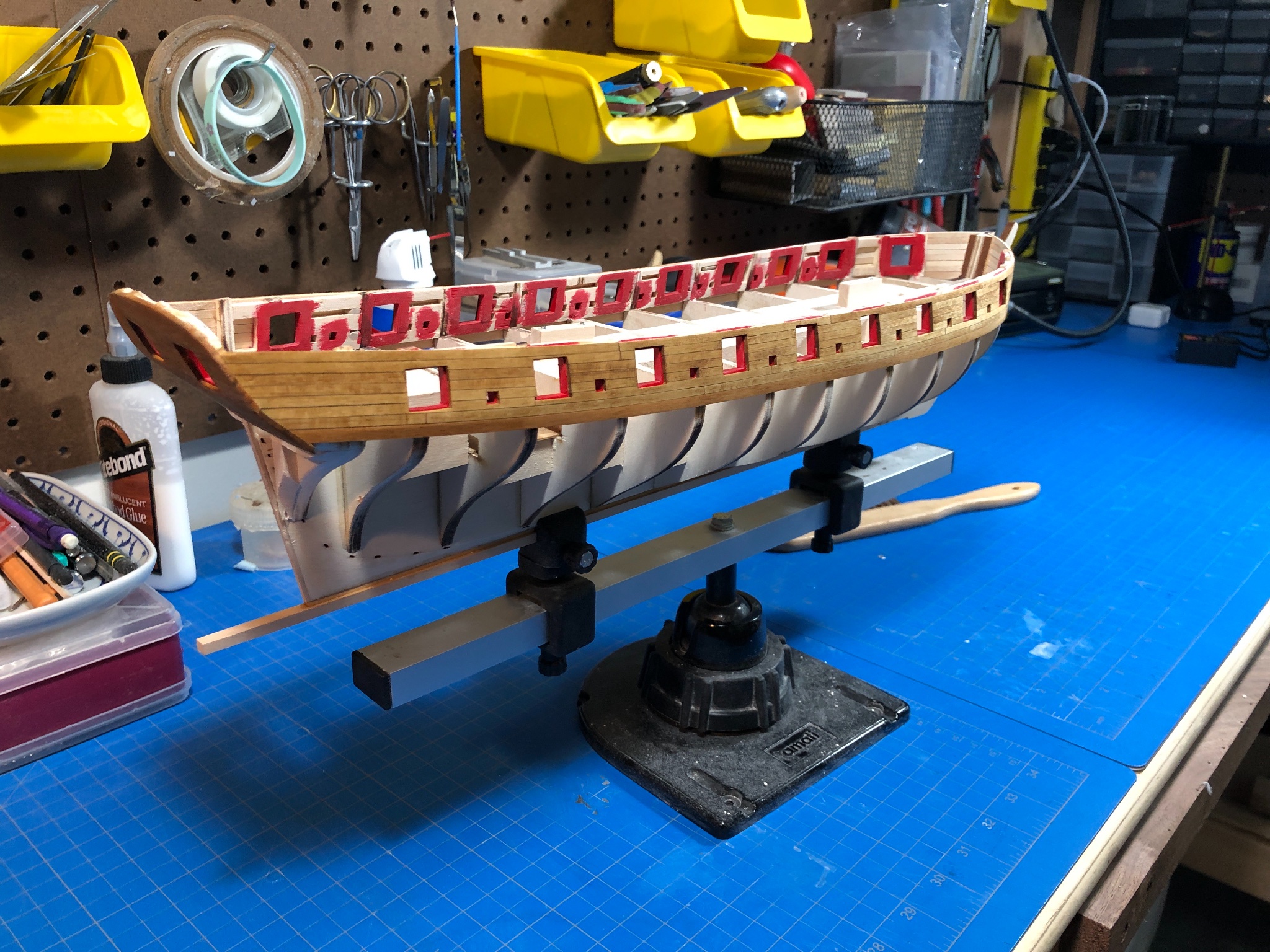
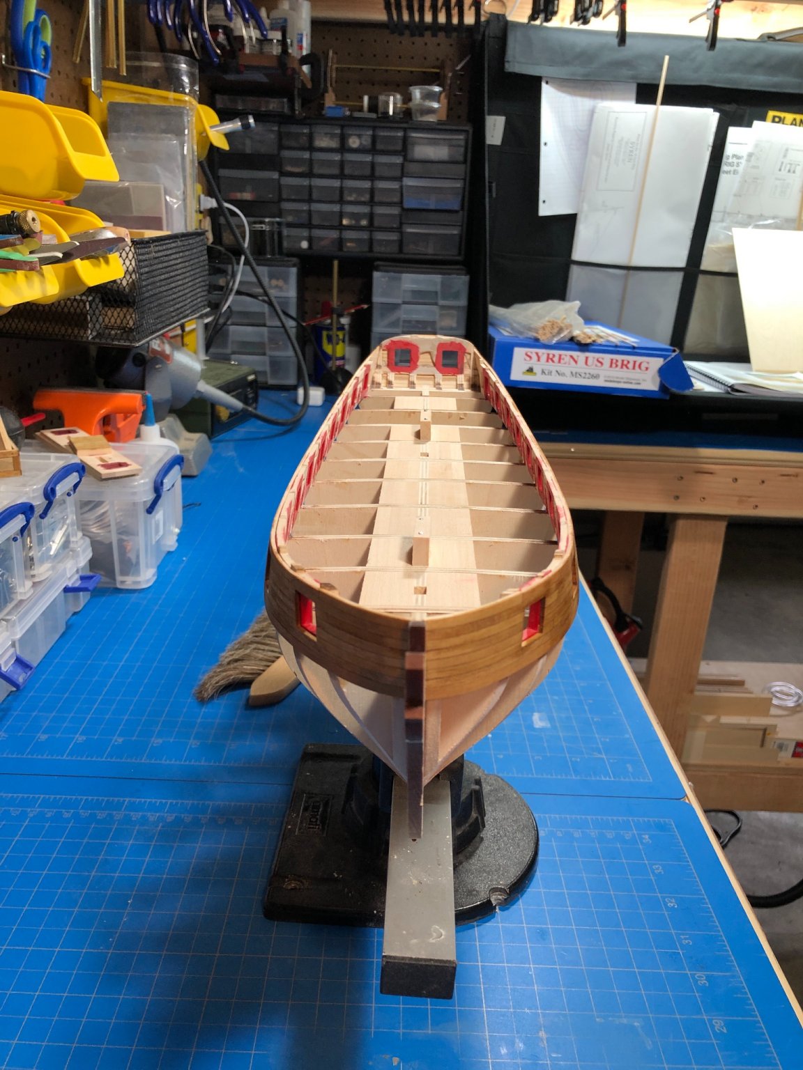
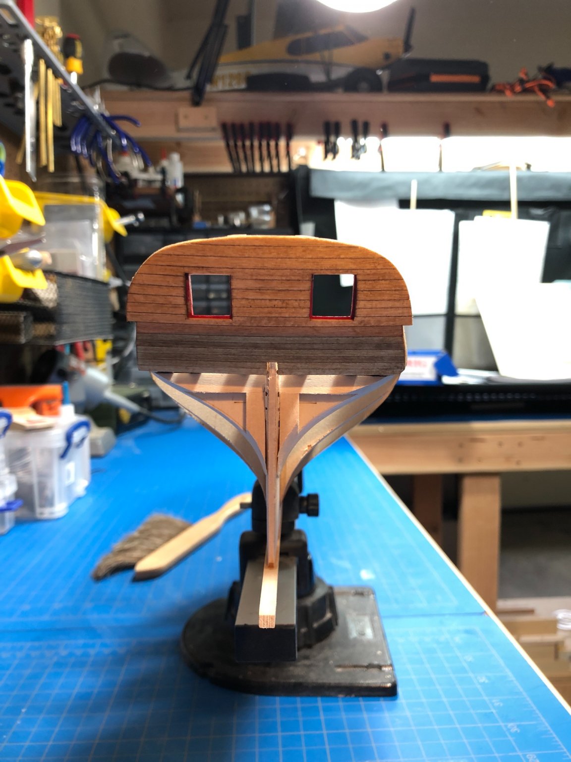
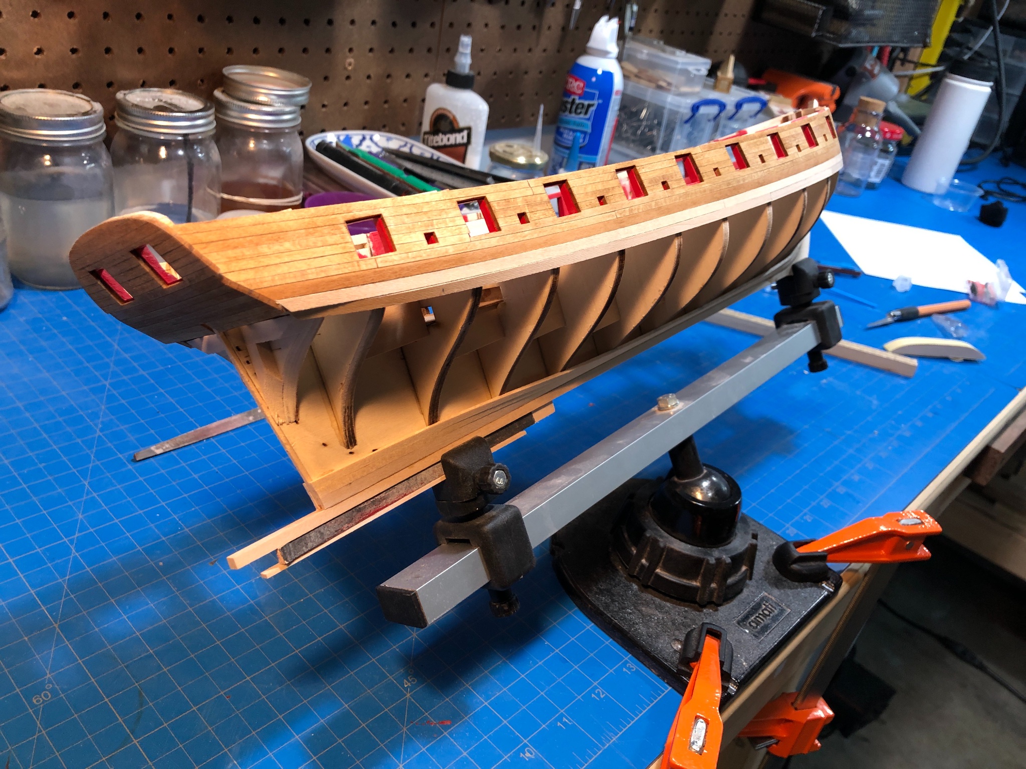
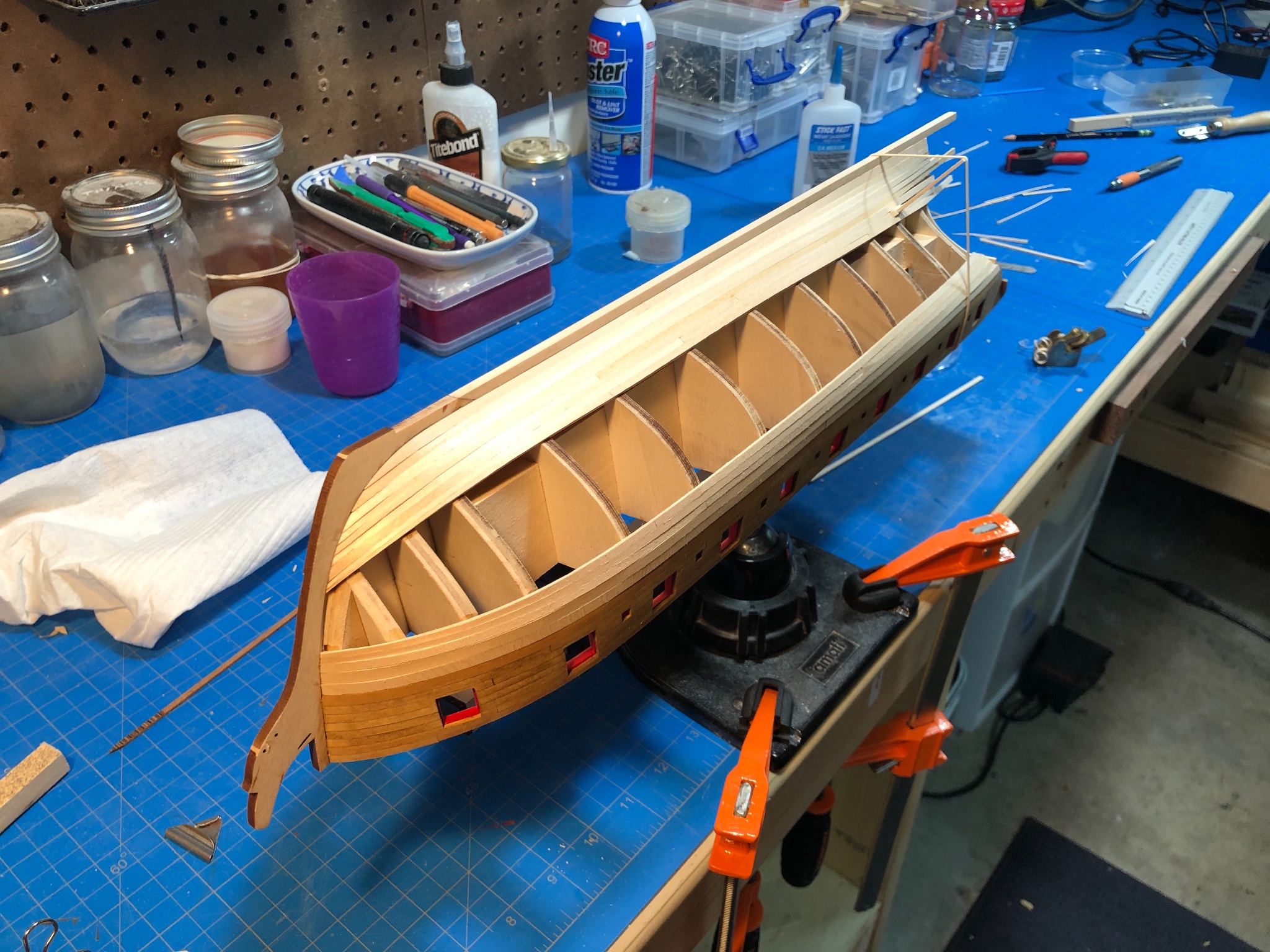
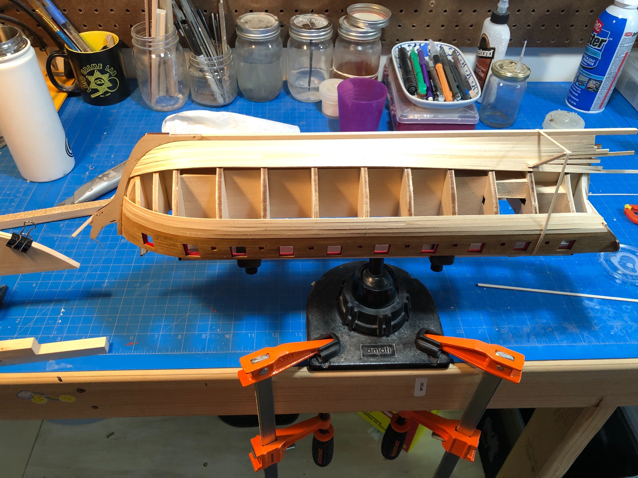
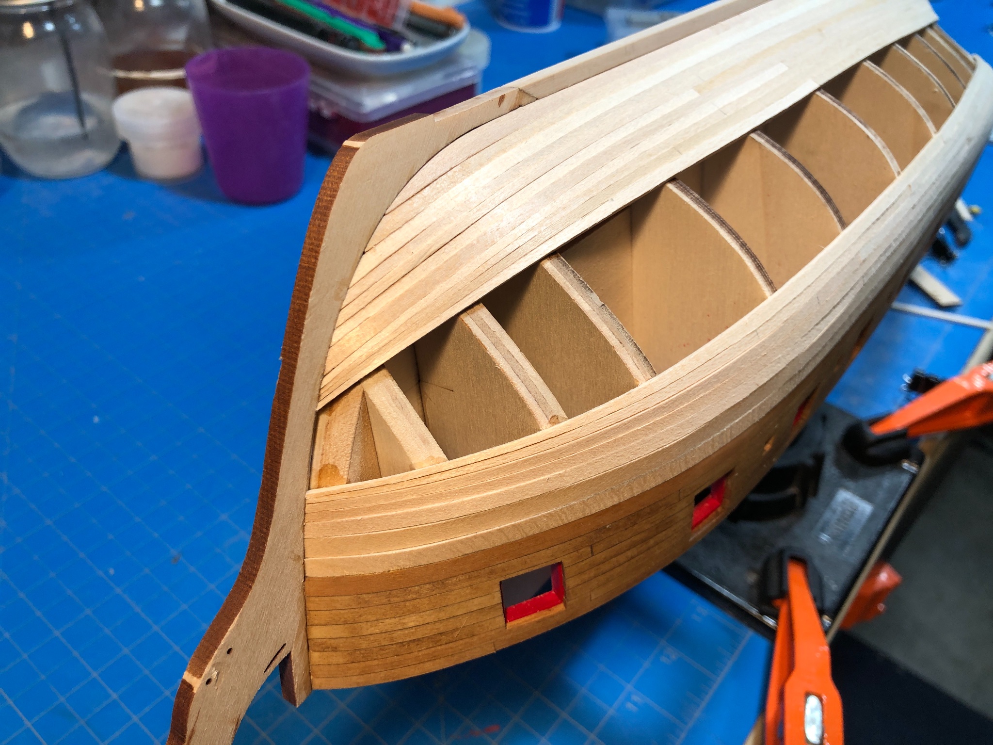
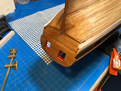
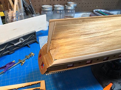
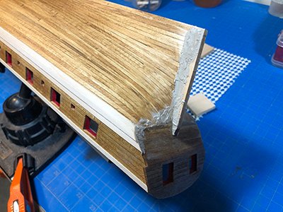
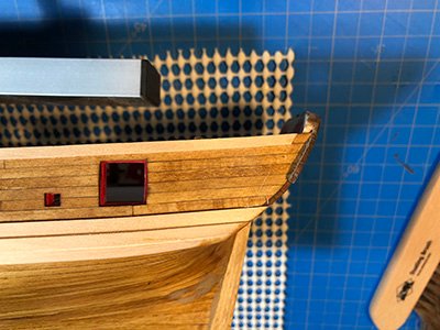
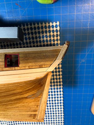
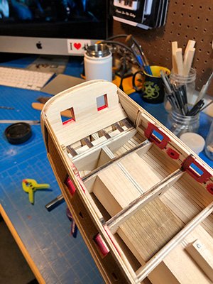
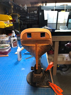
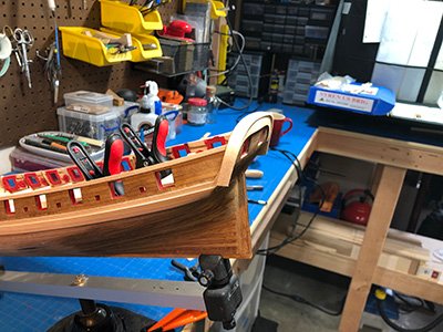
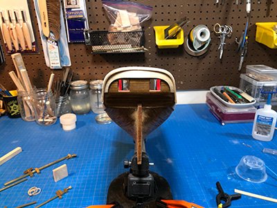
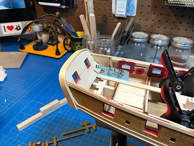
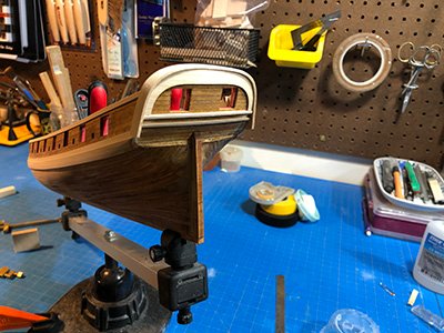
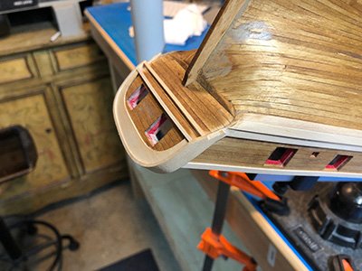
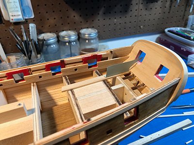
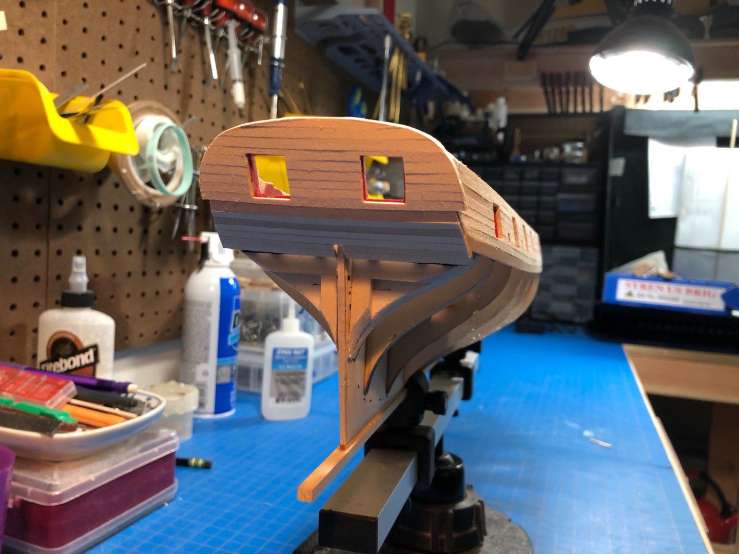
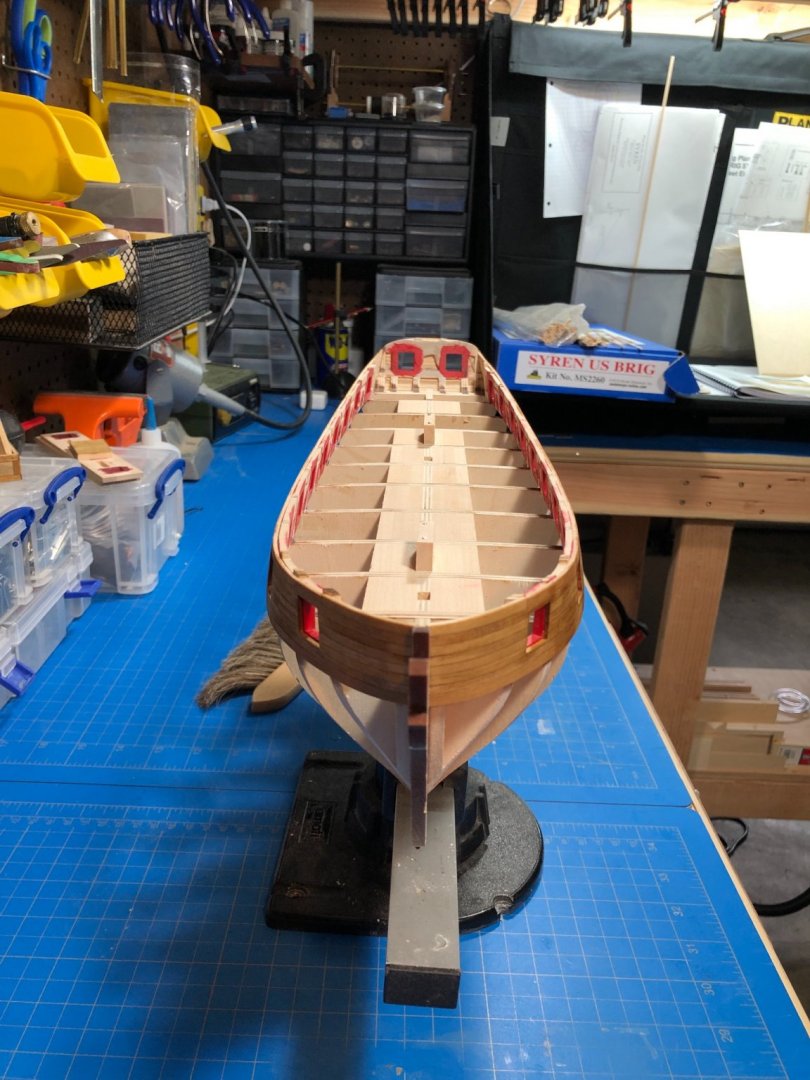
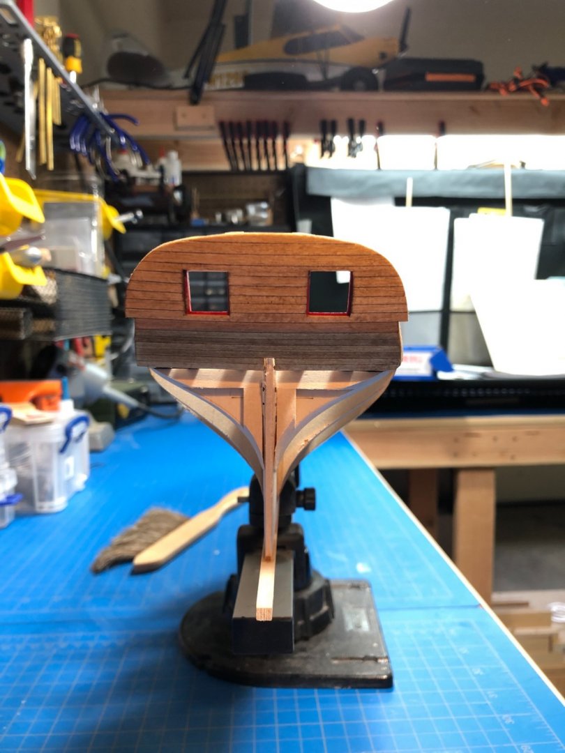
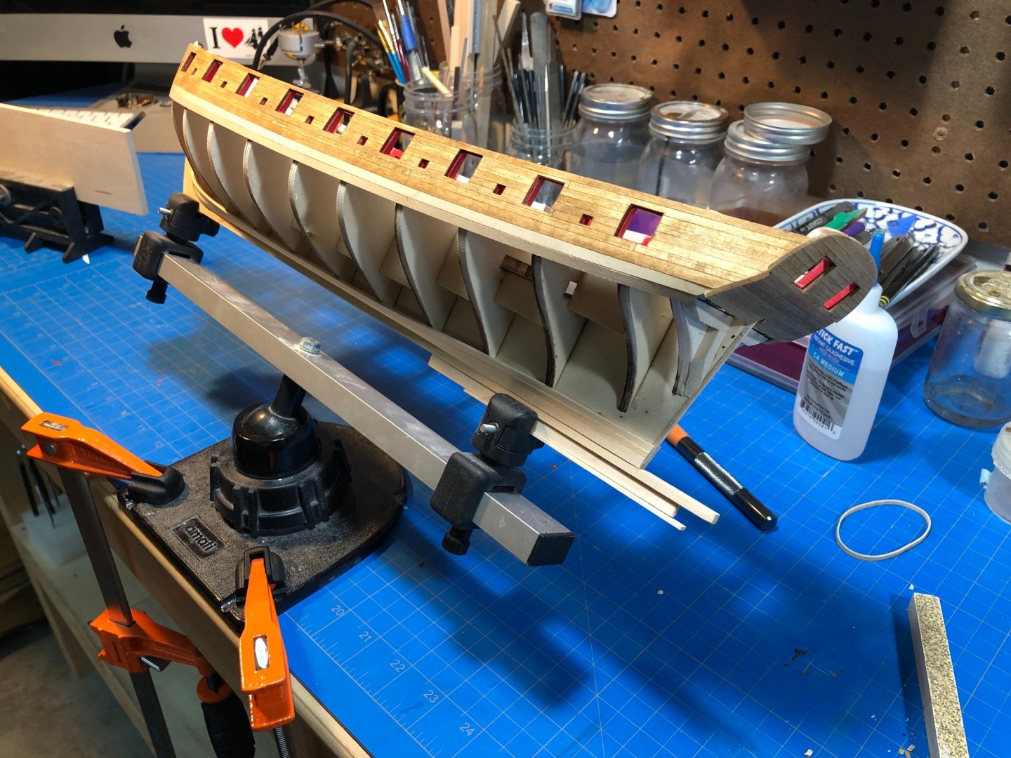
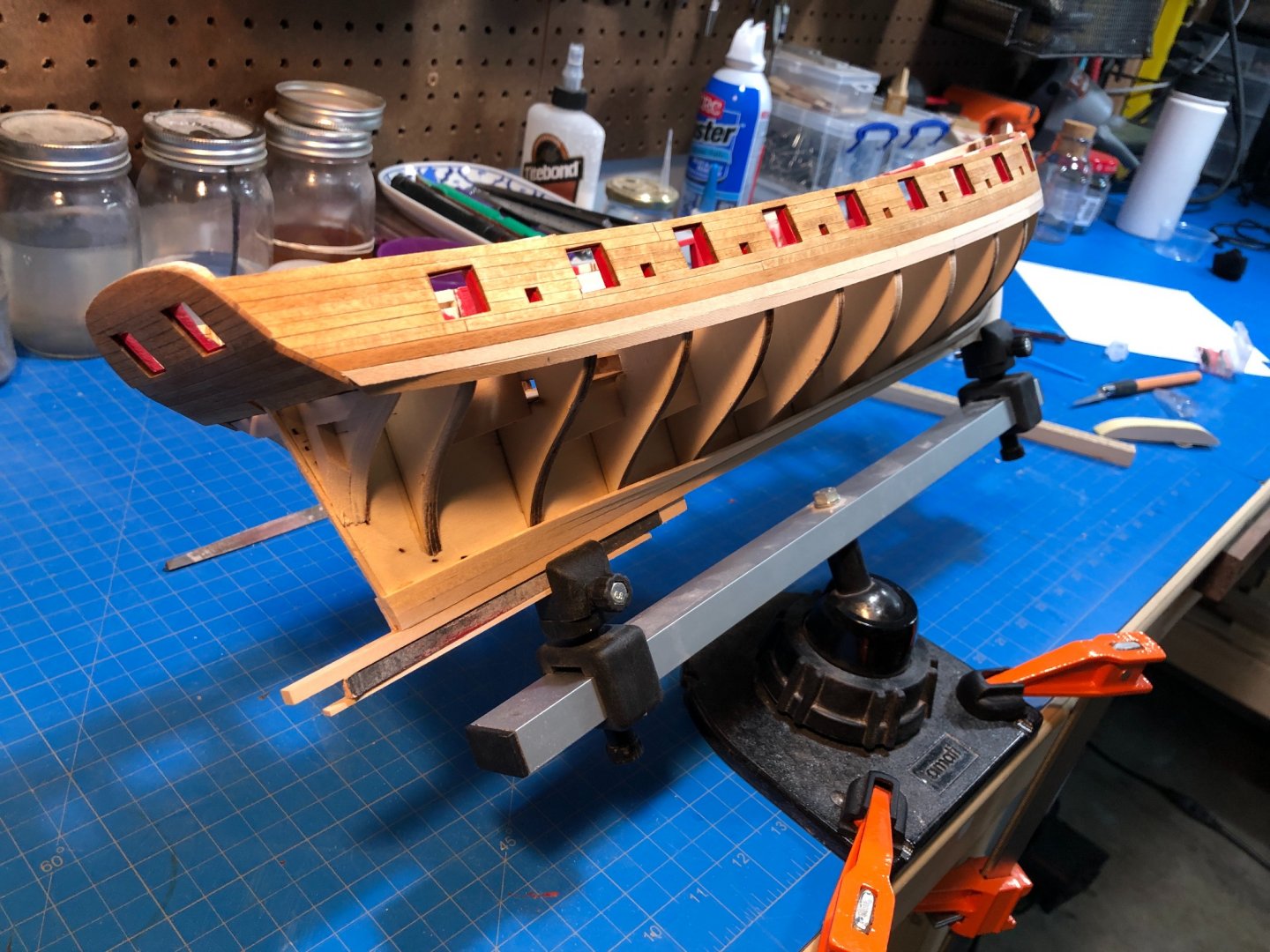
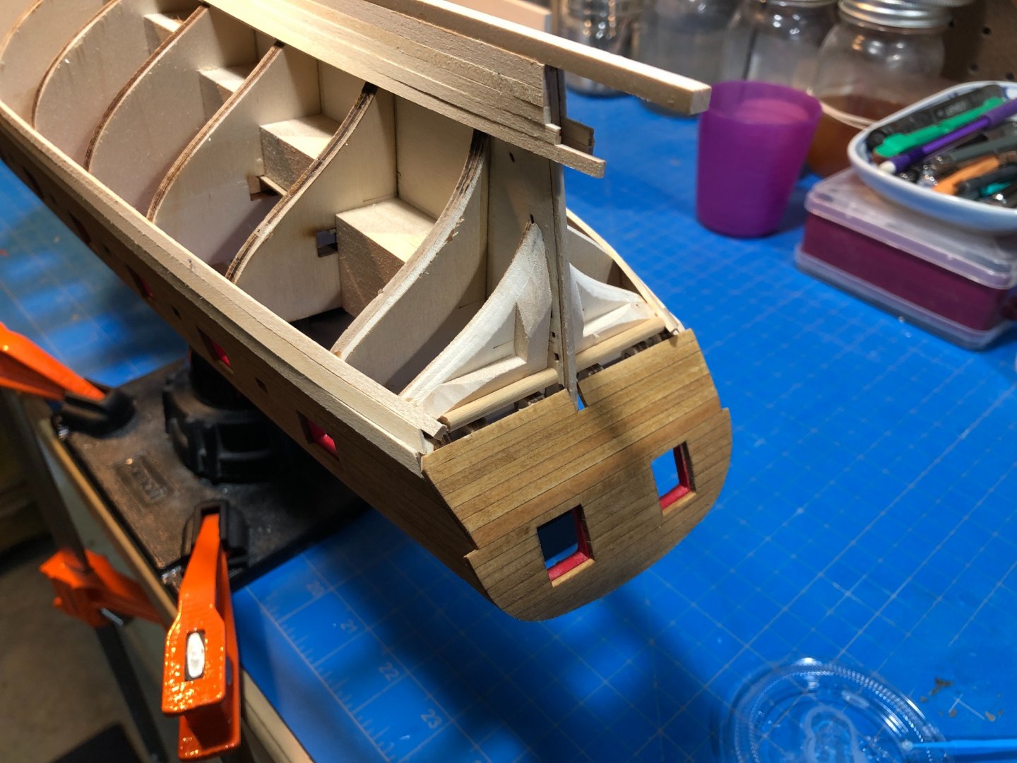
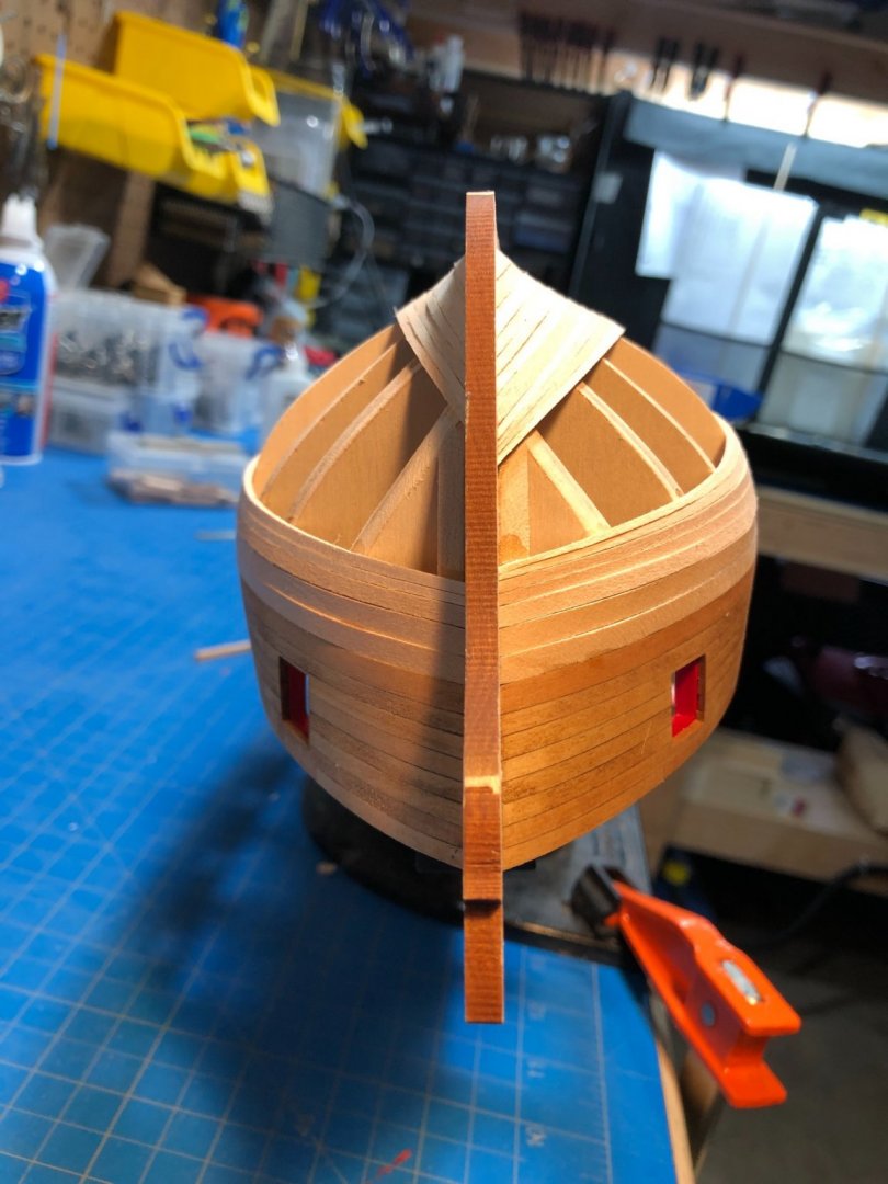
 So Ill try again here... Messing about and realizing the MSW's photo resizing feature is currently broken caused my post to disappear. My fault... was trying to figure out the photo issue and didnt take a copy of my post. Since then Ive gone and resized all my images manually to rewrite this post without it being outrageous with huge pictures! Hopefully that function is restored soon. Anyway, since my last post Ive been focusing on hull details, the stern and transom assembly. I put up the second layer of wales without much trouble, filled and finished them prior to adding the stern post and applying the same finishing protocol to it as well: Im using filler primarily on seams and joints where gaps might be unseemly or interfere with the paint job that is coming later. After finishing I started in on the first components of the transom assembly, called the fashion pieces (odd name). The above photos show them in a unfinished state, as I was preoccupied and neglected to capture the finished product. They are eventually covered by the transom cap so it doesnt really matter. It was at this stage that I added the second transom component over the gun ports outboard and planked inboard. I did not like working with the provided stock for the transom cap as it provided little wiggle room, so I cut a wider strip from some 1/16th stock I and used that to bend and shape the cap. This provided plenty of overlap in all the areas I need so that all I needed to worry about was the initial bend. I could then shape and carve away to the appropriate dimensions. It was here I double checked my with my cannon jig and noticed I added one too many planks and that my cannon jig was faulty! For an embarrassingly long time I could not figure out why my cannon wouldn't line up properly. I realized that I needed to remove the lower plank and cut off that 1/2" of wood that extended past the front wheel of gun carriage. Anyway, I also tacked on two molding pieces just temporarily so that I could shape and carve the transom cap. These will be removed and replaced with the more decorative molding pieces later. Ill leave the transom near completion but not quite finished until I take a closer look at the next few sequences. I also made the correction to my cannon jig and as can be seen above everything is lining up much better. Ive now begun the inboard planking of the gunwales and then onto sanding, sanding and hopefully some final staining and painting before moving on to the cap rail and deck work.
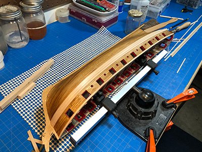
-
I literally just finished this step yesterday. I too had some trouble, I wound up cutting a wider piece and bending it over only to shape it back. Yours looks fantastic. Still finishing mine up today but hope to share by this evening. great job!
-
very crisp, looks great - must be nice feeling reaching this point in the build!
-
It really does.
-
I agree, watching your furniture and other fittings come together is a pleasure! I hope I can achieve similar success when I get there.
- 157 replies
-
- 1
-

-
- model shipways
- syren
- (and 1 more)
-
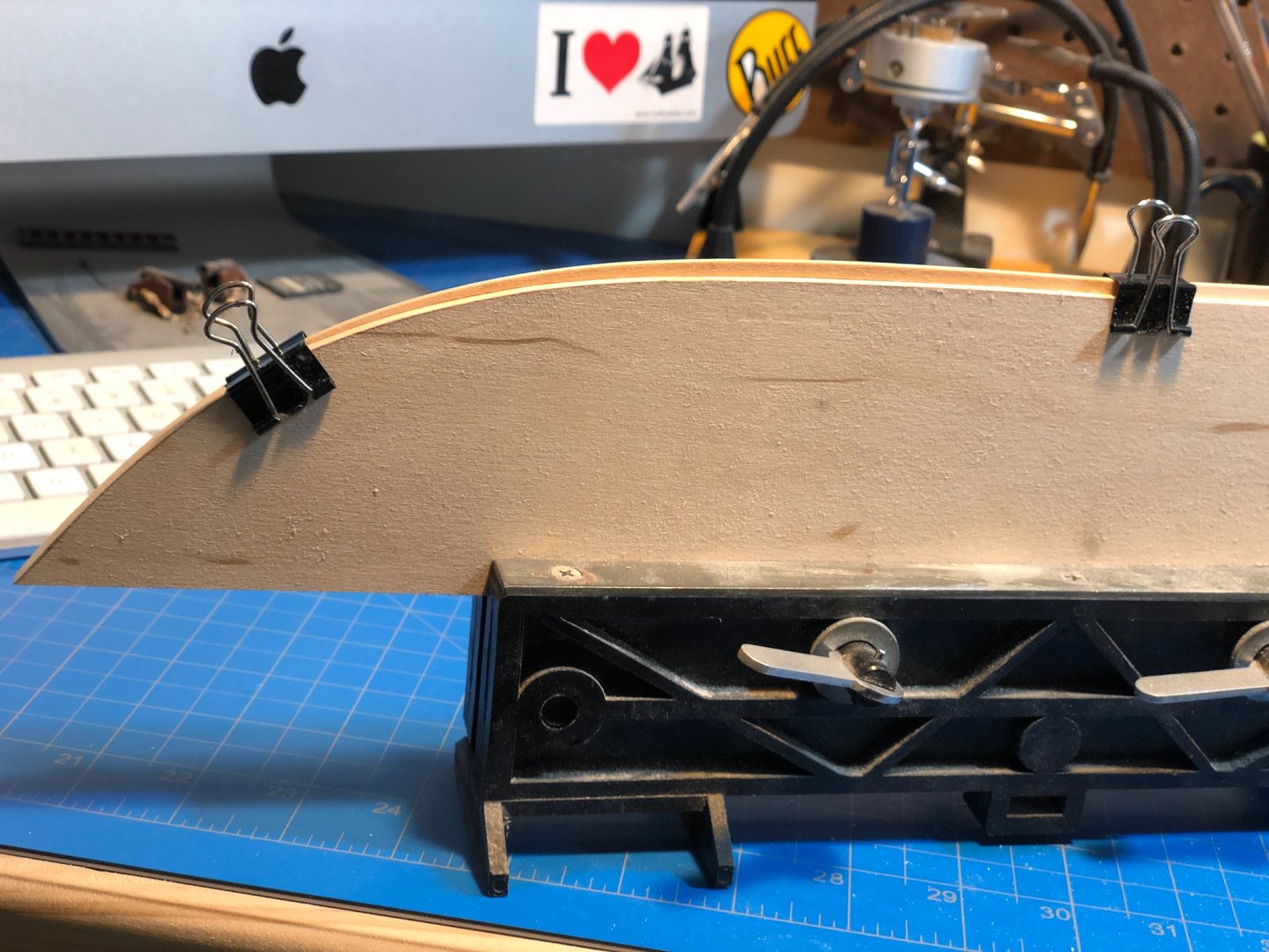
I did this with mine for a different build as well. It was really solid, I had intended to remount it to the board but then I just got busy working and haven’t moved the model since. Cutting the board larger than the model itself also provides a kind of barrier from things coming into contact accidentally.
-
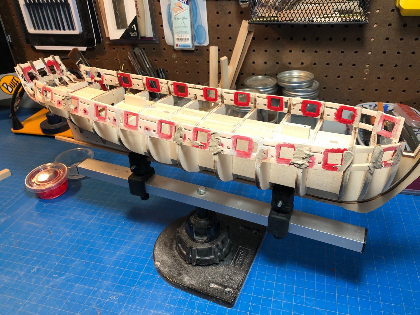
I assume the ones that do not extend are amidships? That was how mine is, and I think it is more or less intended this way. I'm not quite to the caprail step, but my assumption is that it will all come together just fine. I wouldn't worry about it, more important that your gun ports are correct and consistent dimensions. By your picture, everything looks correct. I've only just added the outer wales today, and in the below pic you can see that mine protrude at the bow and stern (click to enlarge).
-
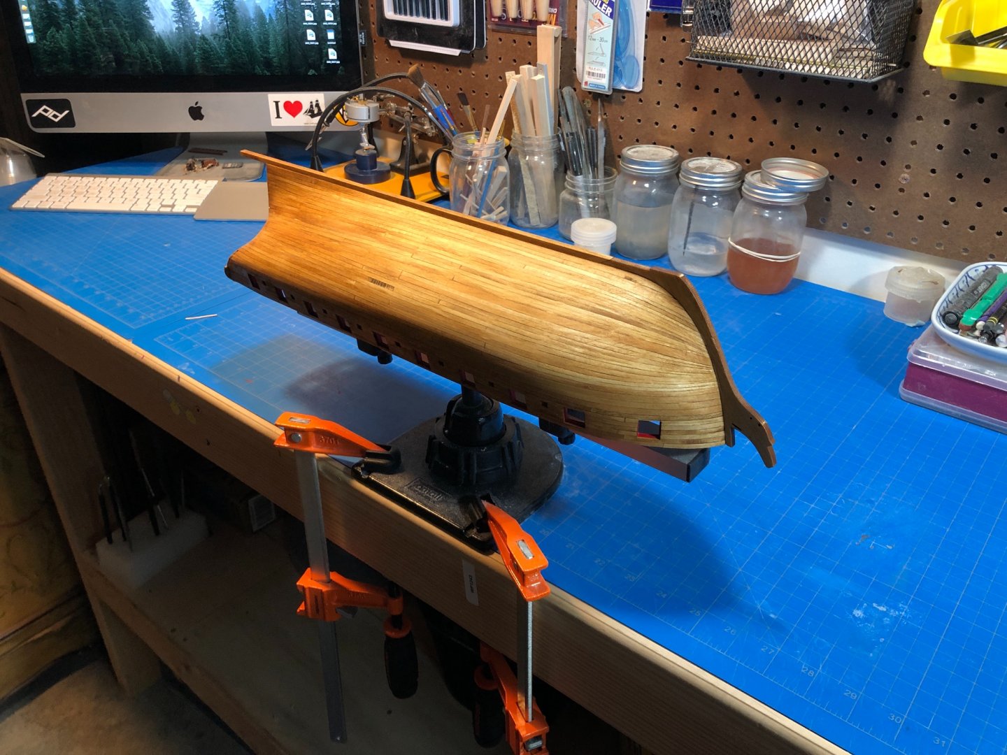
Someone might, dont give away all your secrets! ha. Seriously though, consider a keel clamp from Amati. While the single point of position you have now is useful, you will need more angles and options for clamping as you go. This has been one of my best investments and provides hundreds of useful and strong positions. Also, consider gluing a rail along the deck, and then flip and clamp to that to give another angle in your own setup. You can remove this later prior to planking the deck.
- 436 replies
-
- 1
-
-
- Syren
- Model Shipways
- (and 1 more)
-
Agreed!
-
Looks great, and am glad to help even if it wasnt asked for! Looks like a much smoother run bow to stern. It is amazing how much more rigid the thing becomes as you build in these components. Its during these steps that I found a decent sharp finger plane became very useful for removing the extra material created by the additional wood. Much more accurate (and pleasant) than using sandpaper.
- 436 replies
-
- 1
-
-
- Syren
- Model Shipways
- (and 1 more)
-
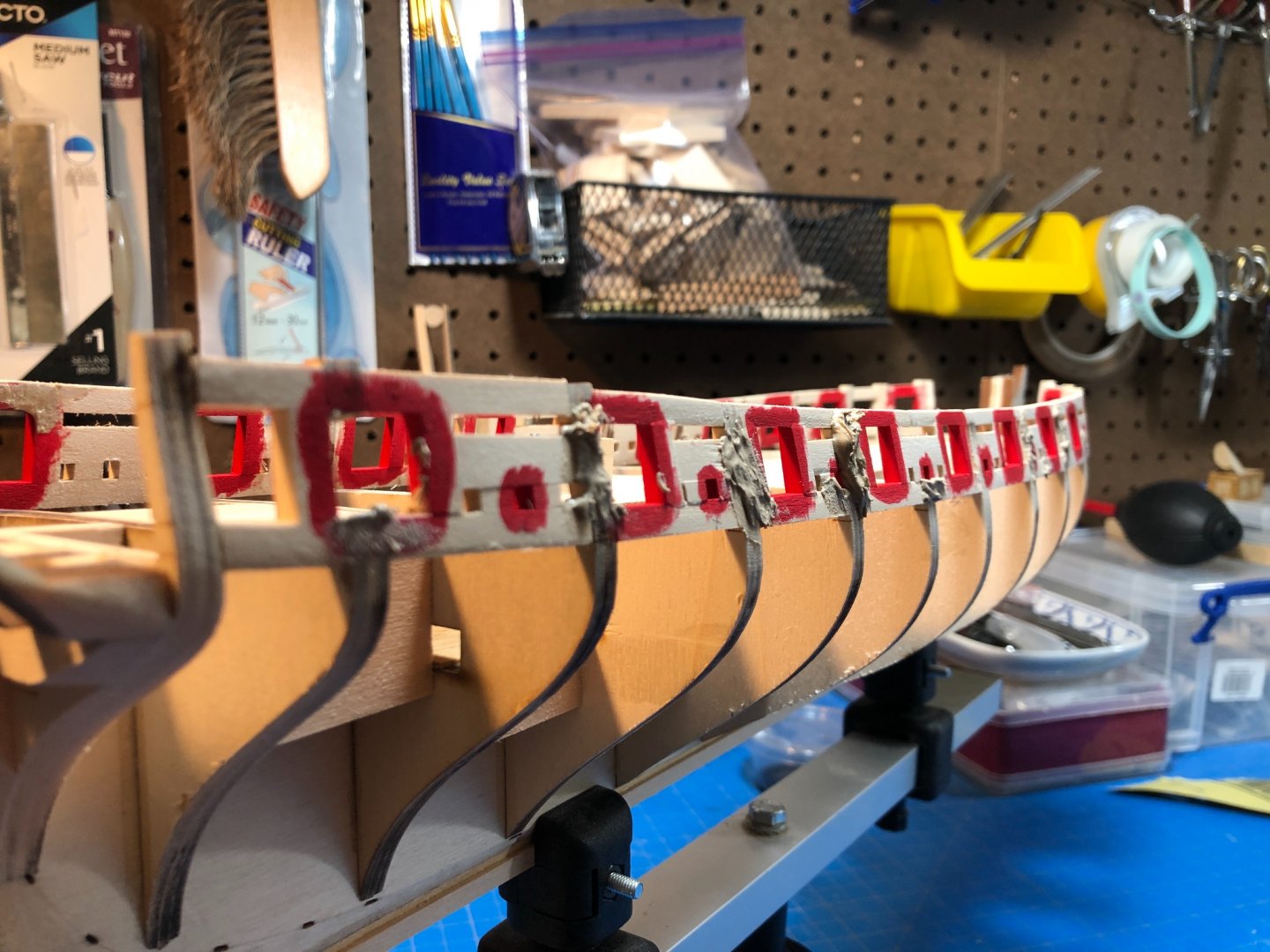
Indeed. I actually thought it was probably the camera exacerbating it, but thought might as well point it out. I think as long as those sills are level then you'll be fine. The ones that would worry me are those towards the stern which "appear" to have a downward angle toward midships. The laser marks are only guides, and really only useful if all else is aligned properly. I tend to go with a mixture of plans, guides and "reckoning." That is too say, if it looks right it likely is or vice/versa. As I don't have the laser accuracy as some of our more seasoned peers do, I rely pretty heavily on look as opposed to plan precision. I appreciate how much Chuck put into his instructions, but for me some of it just doesn't translate well to my personal ability or workflow and I end up deviating often (usually meeting the intended result one way or the other 🙂)
-
Well... thats a tough question. Shapr3d is like CAD, but is not CAD in its truest form. I seriously doubt you'll want to manage modeling an entire ship in Shapr. You can, however, model the entire ship in parts on shapr. But trying to amalgamate all those parts into a single model will likely exceed the capability of your Ipad. You could model framing, or deck construction (in parts) or handled as seperate files/projects. You could even model a hull, but its not as easy as using regular AutoCAD. Working with lines and then extracting a hull form from that is not as precise (or is not as automated). Are you trying to 3d print parts or plan a build? If you you are planning a scratch build, then this CAD is not the right choice in my opinion. If you are designing a capstan, or cannon assembly or some other small part then its great and will export to whatever 3d printer you want really well.
-
Nice progress. I think much depends on your sandpaper choice as well. I found that gator sandpaper to be noticeably more efficient than the standard brands in working with the ply and other weird grains. Also, I found the rotary tools harder and less precise, which could be my own fault. I took a 1/2 x 1/2" square dowel and cut it down to 3" long and then ground a square float plane landing float shape into it (Im also an RC pilot). This provided a square, but also non-catch shape to fair the inner bulkheads. Using the gator paper, this process did not take long at all. Also, the gunport sills seem to be running a bit squirrely, I might consider lining these up a bit better as this will become quite apparent when you eventually get your gunports planked in... they should have an even sweep and be level. I found that cutting out a 5/16" jig helped a lot to get the gunports sills and lintel spacing consistent and square. The ends of each of those pieces should be meeting up and following the same line. Looking forward to following along.
-
Very interesting! I haven't the faintest about origin, but can tell you that you have quite a treasure there! Could also be in reference to Harold Hahn - who knows?! I'm a rare book conservator and have worked in and around bindery's a long time. What I can tell you is that the Valve company likely had an in-house spiral binding machine and a stock of custom spirals with their name printed on them OR a stock of blank drafting journals pre-bound. Like a company might order pens with their name on them... Anyway, this was for employees to bind up their own notes/designs/drafts to keep in-house. This is quite common and seen in archives etc. My guess would be the author worked for M&H and took advantage of what was available at work to keep his manuscript together. Either scenario is totally plausible. Should you be desirous of some stabilization, repair work and/or consultation locally for preserving your find let me know, I can pull a name from our cohort of peer-reviewed conservators. I'm sure there is someone in your area.
-
Yes. I use it all the time. Got a question?
-
I suspect Ill join the cohort of those who've snapped one of those frames as well! If you don't mind Ill follow along!
-
Yep... that's basically what Ive decided as well.
-
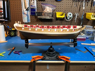
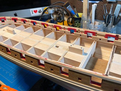
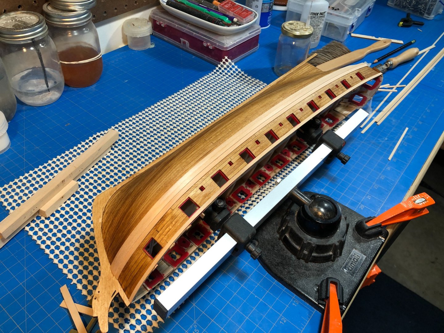
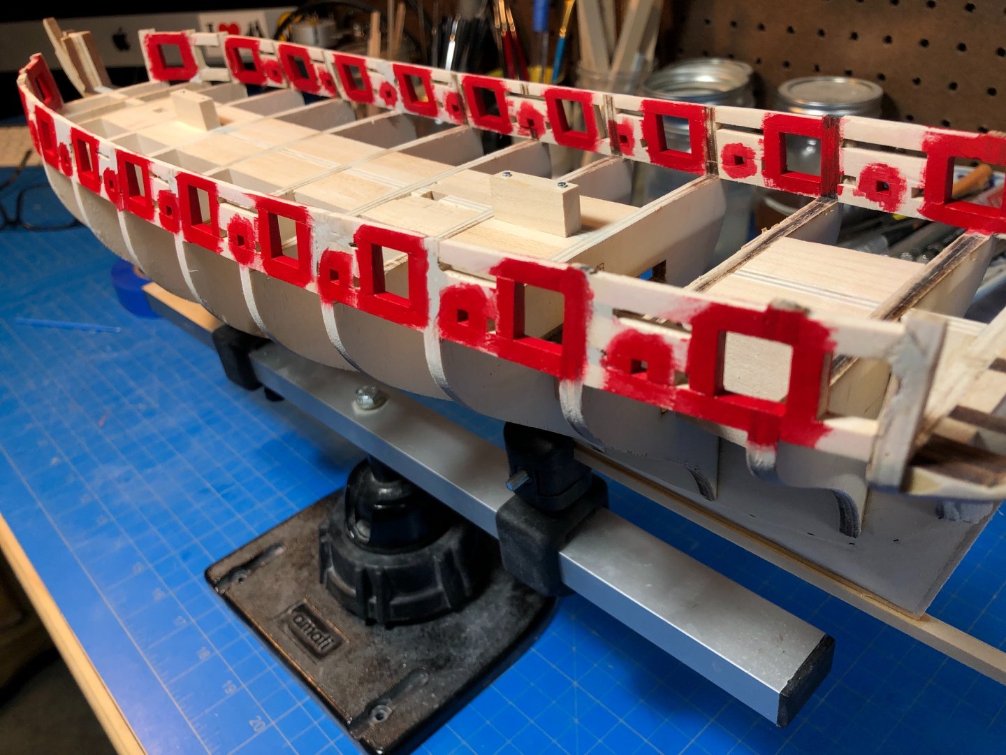
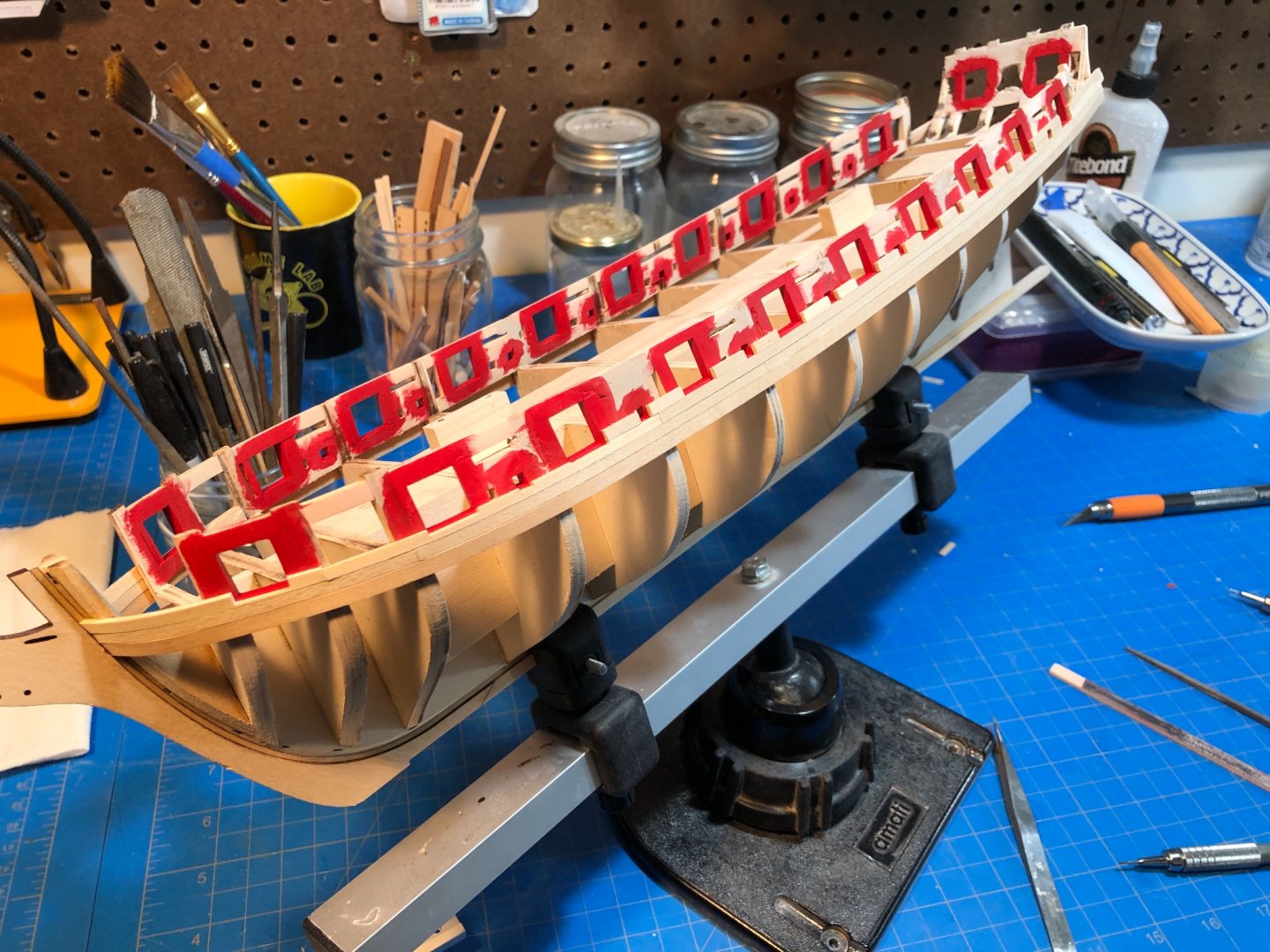
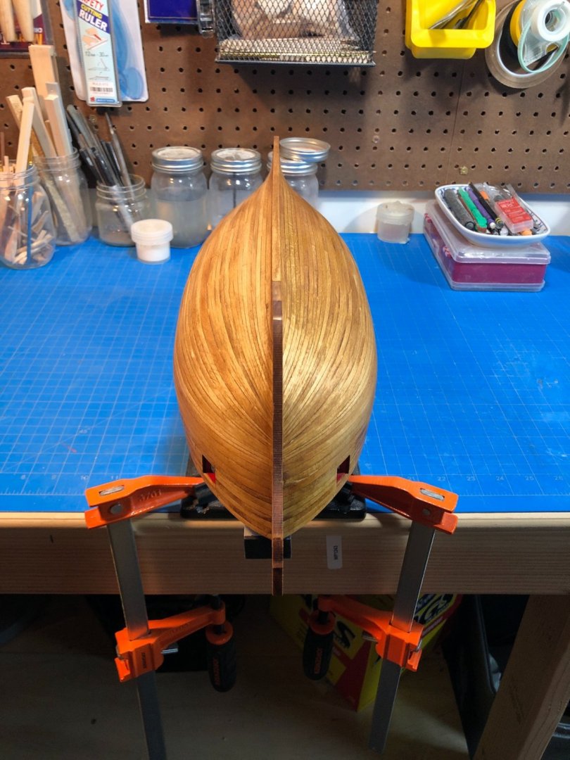
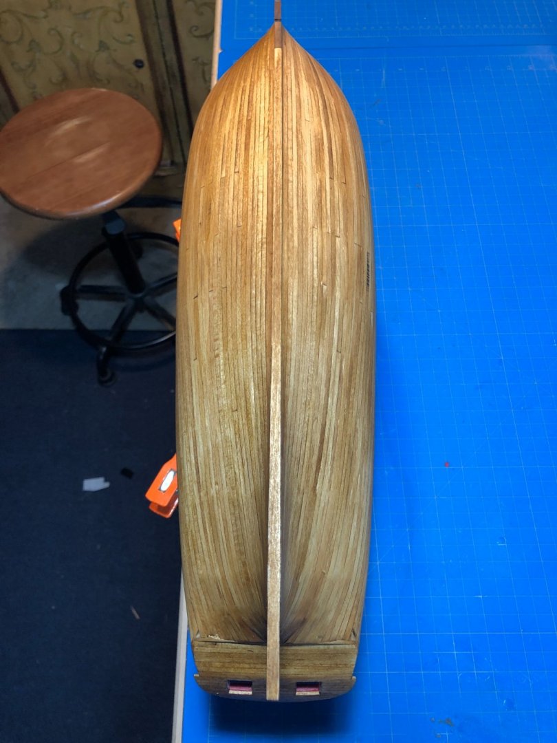
Yes... Ive been plugging away. School has started up and with COVID the kids are homeschooling, meanwhile Im also still working from home so things have been pretty hectic. The last few stages of my build have gone well. Slowly, but well. Its amazing just how much time some of these steps can take, and Ive just been chipping away as and when I get a few hours in the shipyard. Also, I may be overdoing things a bit as my patience has grown and my ability to overlook flaws has diminished. Just getting the painted gunports finished took awhile, as I really wanted them to be just so, and thus open many hours filing, filling, painting, and then in some cases going over them all again. I really look forward to a time when I can get some of these things done right the first time. The result is that my gunports are really squared up and have nice clean edges-which was the goal.. I then started in on planking in the sills and lintels. This was a pleasurable enough task, but did take a LOT of time as notching in the along the ports took a lot of trial and error until I figured out a system and tool combination that provided consistent results. I planked up both sides, sanded and then stained. I was quite pleased with how it turned out. The transom came out well, too. I opted to deviate a bit here where the upper transom calls for a single piece of laser-cut 1/16th thick sheet cut out for framing in the ports. I chose to simply plank it in as well. This may well have been a mistake, we'll see when I get there. Then began the lower hull planking saga. I think overall Im getting closer to doing it right, and farther from doing it wrong - BUT there are still a lot of problems... I mean, its better than I was expecting it to be. Ultimately this area is painted over and then coppered so Im not overly upset, and Im glad Im only gonna need a tiny bit of filler at the stern. I used a combination of tapering, tick marks, and edge-bending, with the last plank on both sides needing to a be spiling job from a piece of sheet I had laying around. I also had a bit of trouble at the transom where the planks bend upward to meet the transom and stern post. I needed a bit more support to get things to lay down properly and so had to improvise some filler and an additional plank. Of course that was not the only improvising that was required - meet the rubber-band/post clamping jig. Some other planking shots and my edge-bending jig: And here is where I am today: Yes, I stained it. Why? I have no idea. I just felt compelled, and yes I am still going to paint it black per the instructions. Next I need to add the second layer of wales just under the ports, and move onto the transom. Anyway... its coming along. As for the trunnels I agonized over in an earlier post, I decided to forgo them completely. I think at this scale they'll be a detail that will detract rather than provide to the overall piece. Thanks for watching!


-
Hey Bob! Funny you should mention it....
-
Can you confirm the entirety is Syren product?
-
Clean work, glad I discovered this build before it was over!
- 164 replies
-
- 1
-
-
- first build
- model shipways
- (and 2 more)
-
Its looking really great, I very much like how the carronades turned out. Lots of clean details, my favorite.
- 950 replies
-
- 2
-
-
- syren
- model shipways
- (and 1 more)
-
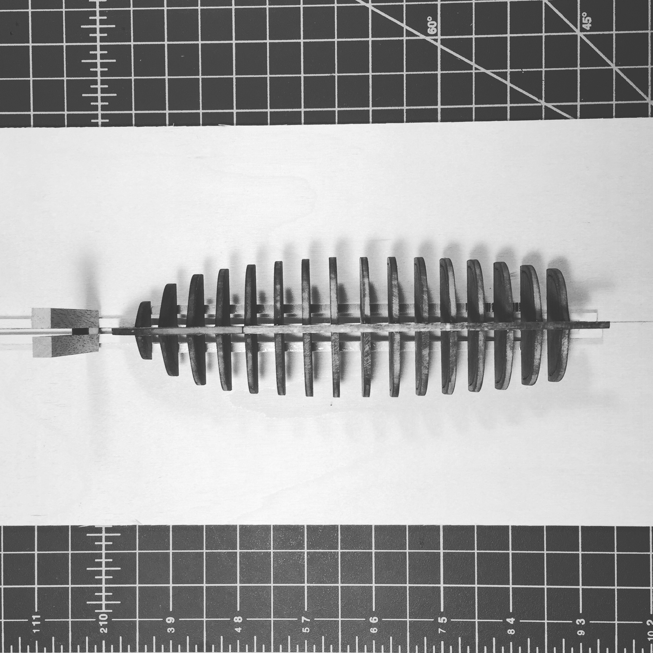
Model Machines currently sells a selection of blades that correspond (perhaps not exactly) to the above document. I buy direct from him.
-
Seems too large to be a button to me, I agree its more likely a knob or handle of some sort.
-
Cutting and shaping masts: tips on how to do it.
Justin P. replied to Peterhudson's topic in Masting, rigging and sails
I think people can sometimes get bogged down in equipment and machine tools if led to believe they are "needed" to achieve a satisfactory result. I think if your are an efficient and knowledgeable user of mills and lathes then by all means, we all do things our own way. Not knowing someones experience or skill set with mills and lathes, they wouldn't be my recommendation for something like masts and spars. I think its important to remember that perfect results from machines require a certain level of understanding and knowledge with those machines. Hand tools, in my opinion, can be a bit more forgiving even if result as not as exact. I know my scrap pile consists of far more machine mistakes than it does mistakes made by hand tools.