HOLIDAY DONATION DRIVE - SUPPORT MSW - DO YOUR PART TO KEEP THIS GREAT FORUM GOING! (Only 24 donations so far out of 49,000 members - C'mon guys!)
×

Justin P.
-
Posts
1,008 -
Joined
Content Type
Profiles
Forums
Gallery
Events
Everything posted by Justin P.
-
I looked at this system as a way to produce relief carvings at scale for ship models. In the end I wasn't convinced I would get the fidelity I wanted and skipped the deep dive. I look forward to seeing what you can do with it!
-
 Thanks Mark, Im happy with how they turned out - but like the knee's I can tell I might eventually NOT like them. I did mock them up on a smaller panel, but I wonder if my mock-up wasn't large enough to get a good feel. Ill just need to spend some time looking at them. Appreciated Matt, I am glad I went ahead and changed them out. Im not sure where my head was at when I first did them. Thanks Bob!
 -
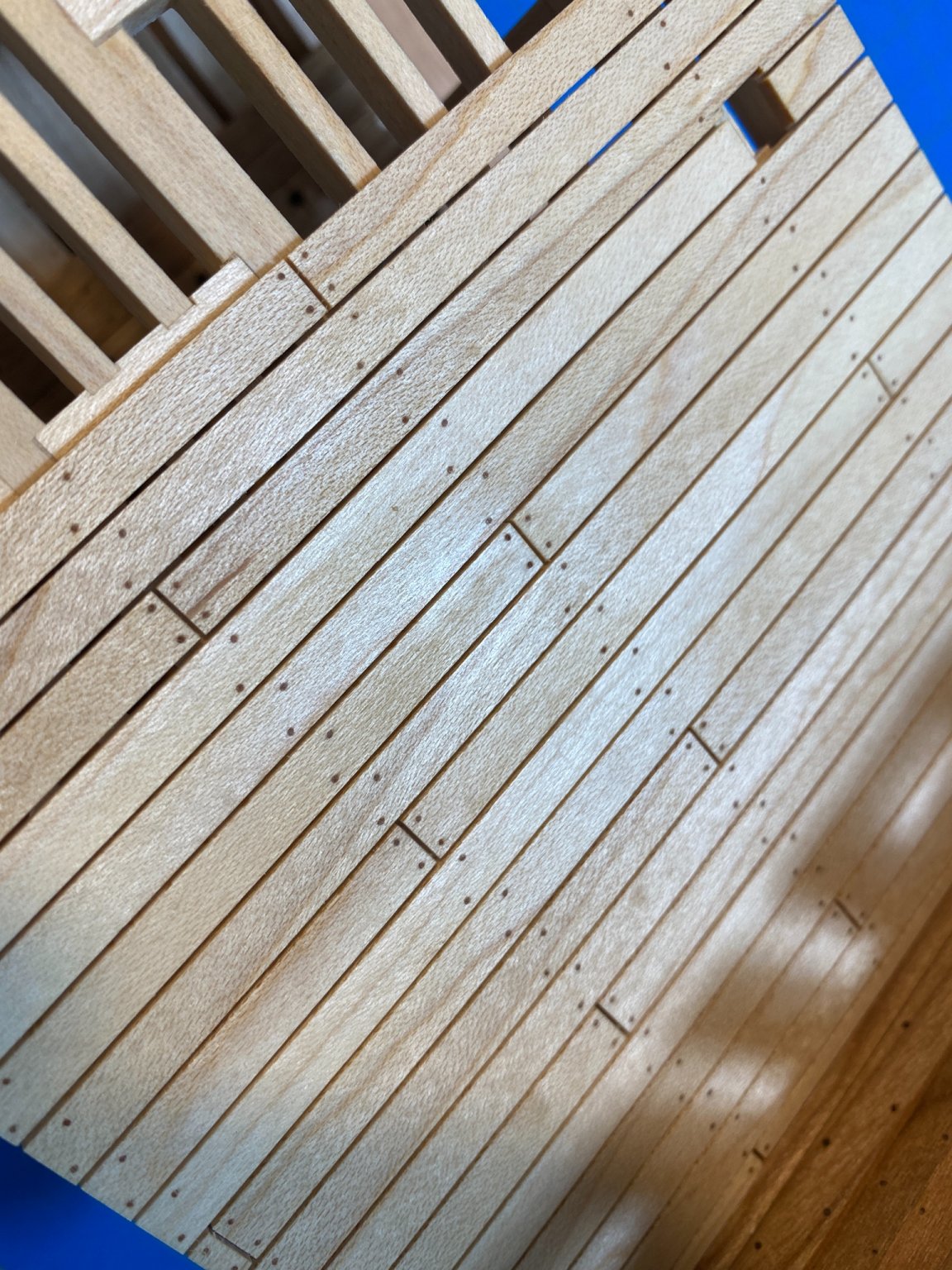
Thanks! I did use a thin brass shim for spacing (another trick purloined from Chadb's build). The putty caulking does give a great impression and provides a nice level of detail.
-
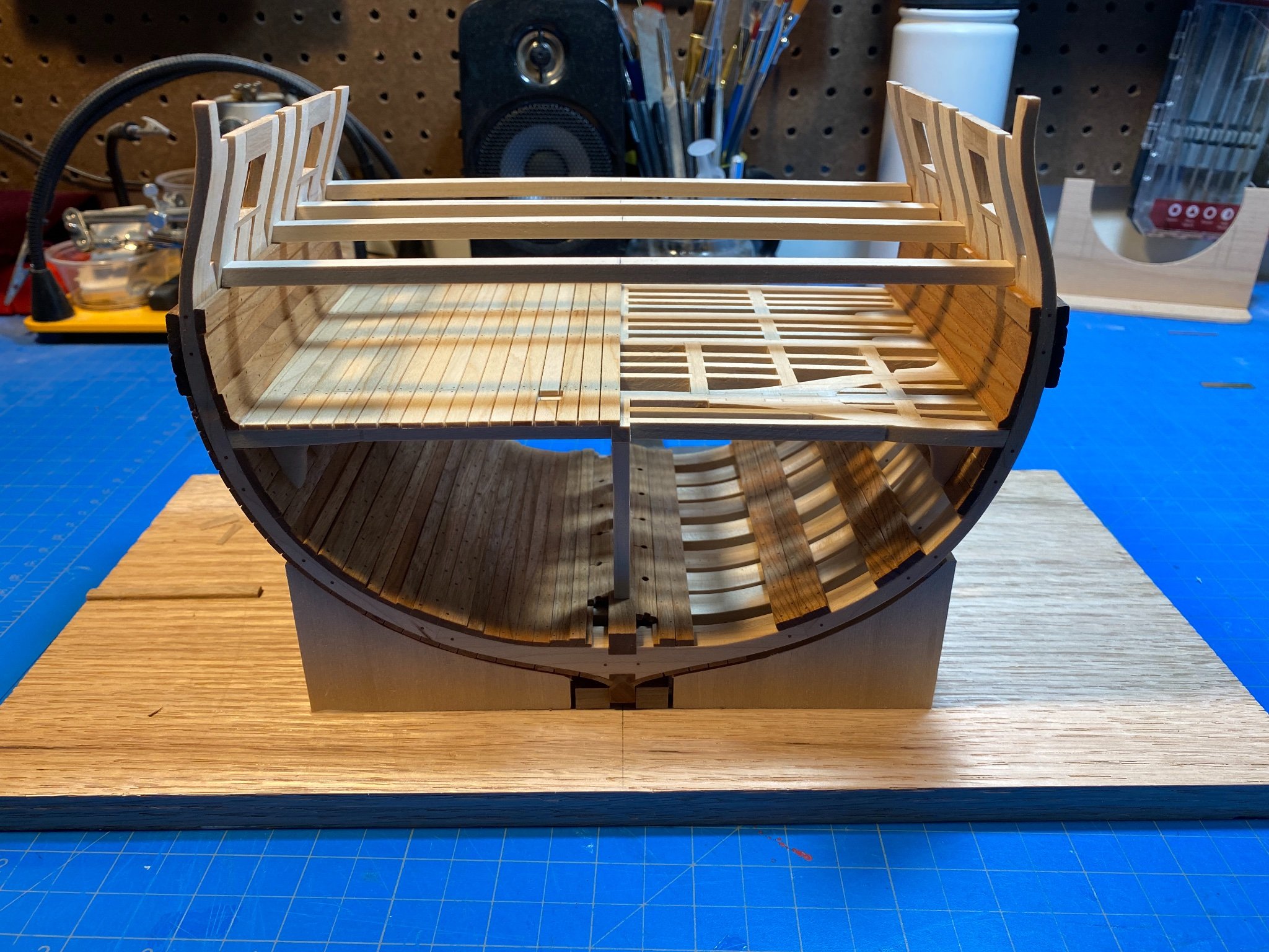
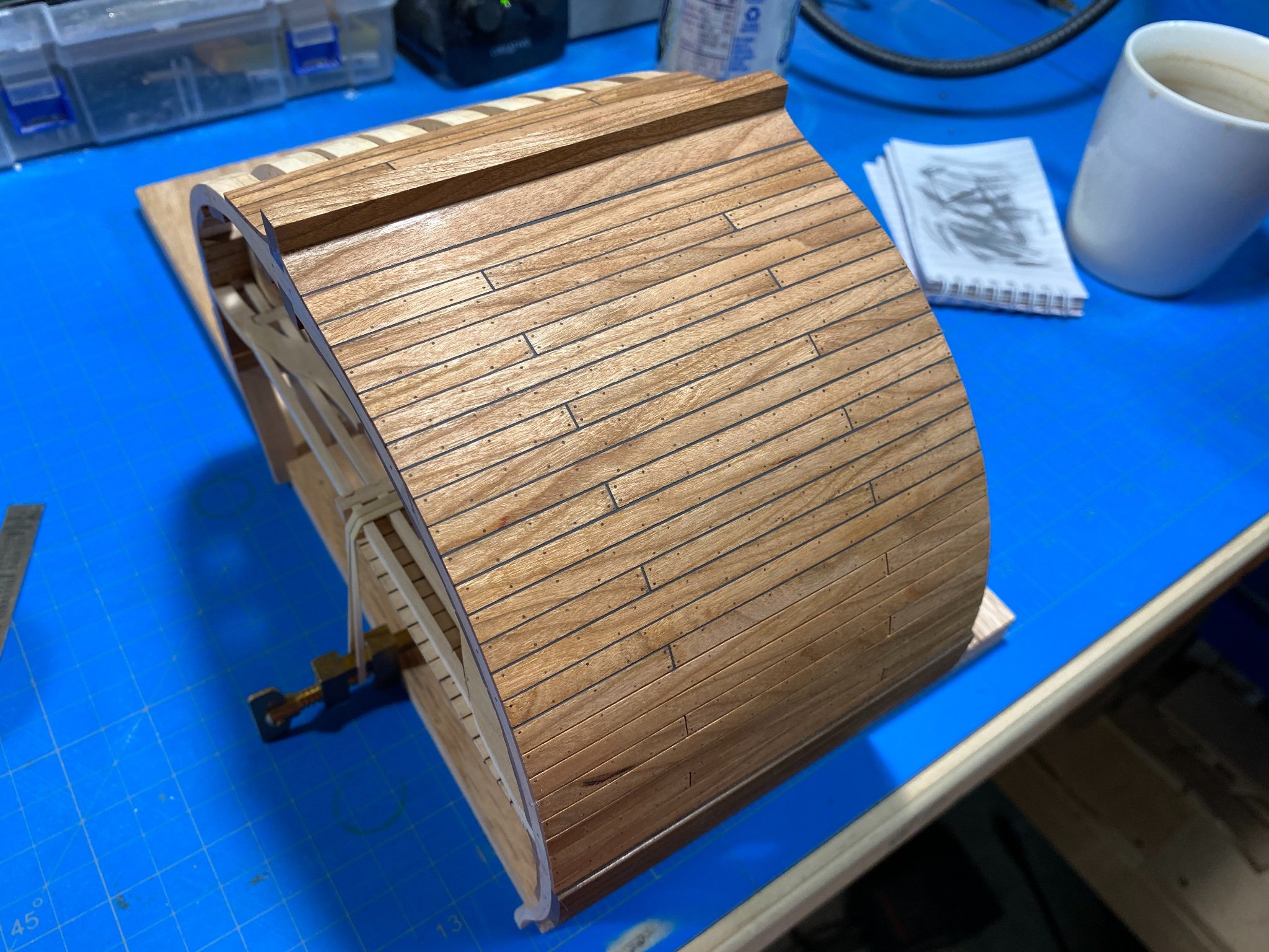
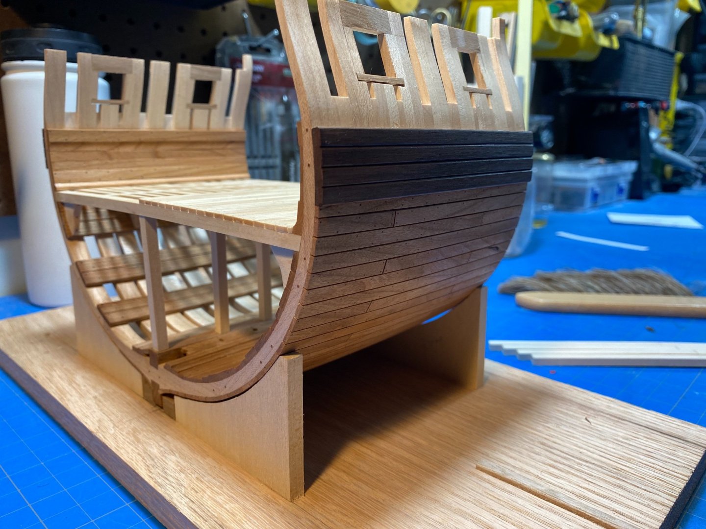
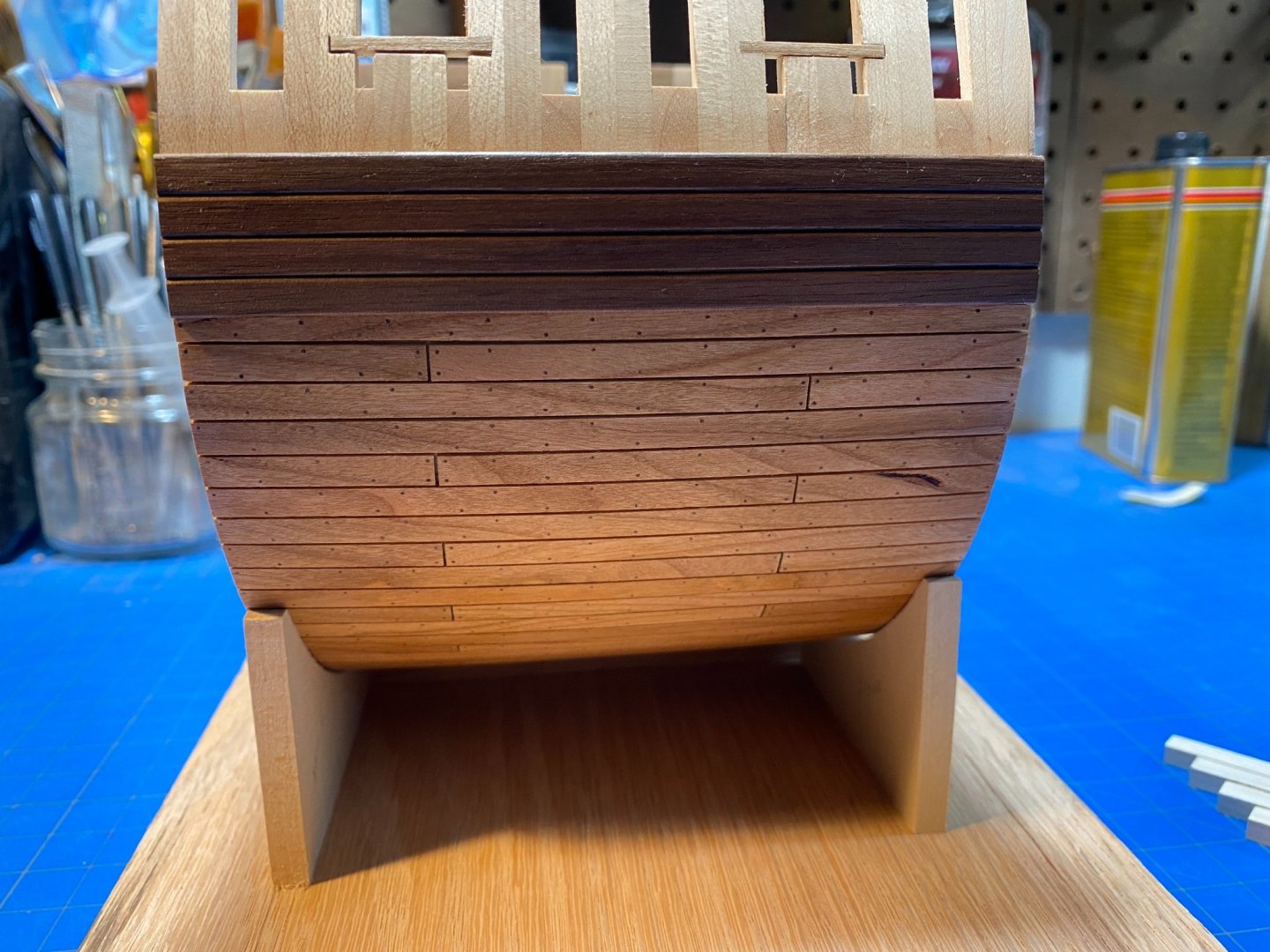
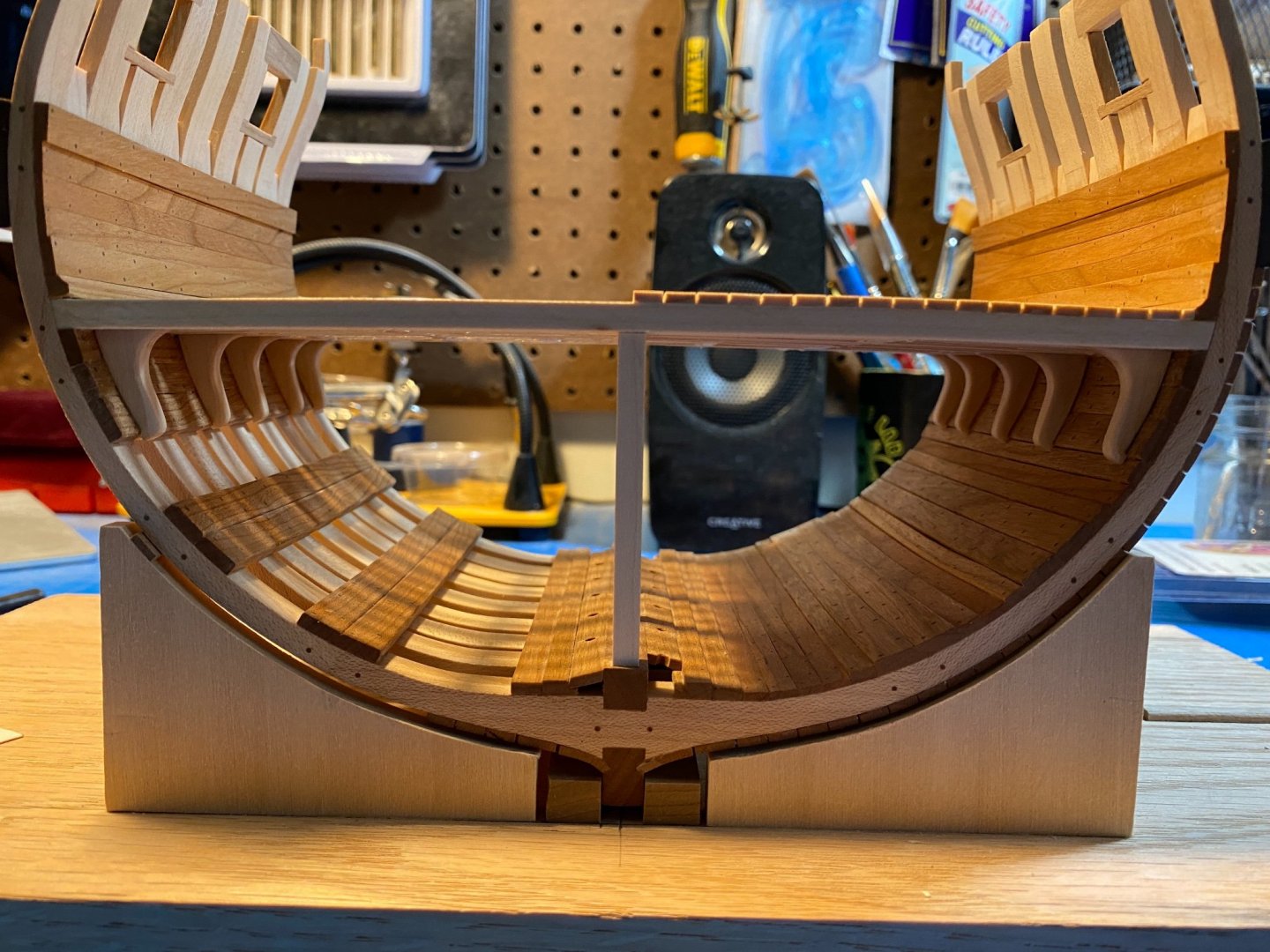
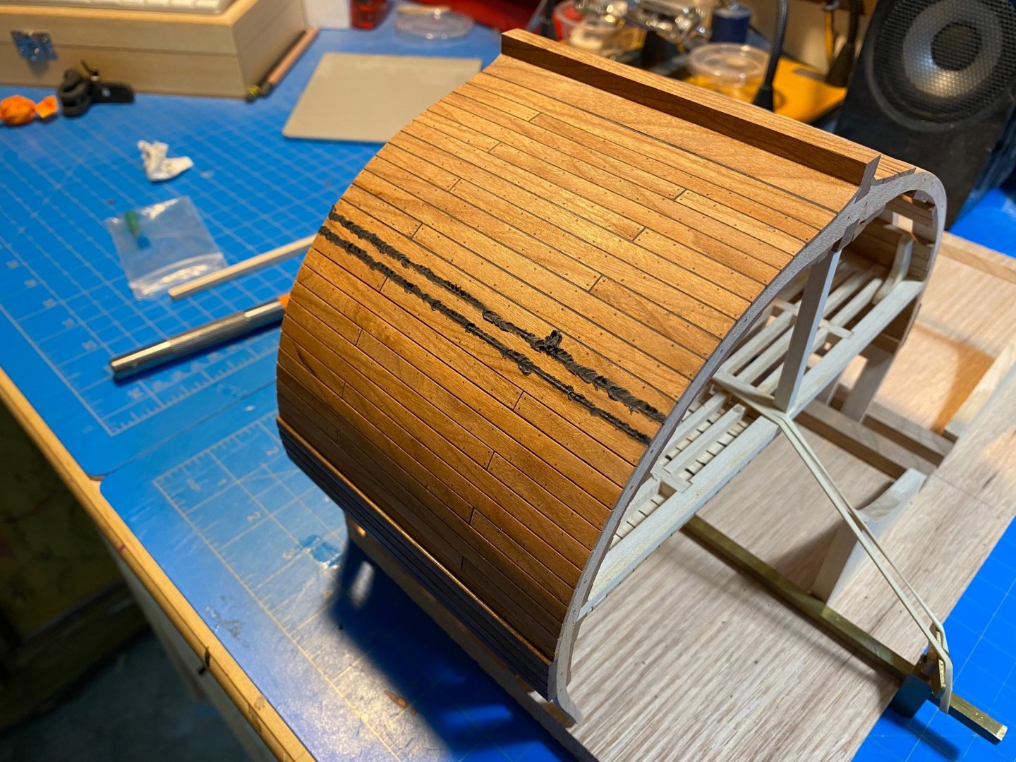
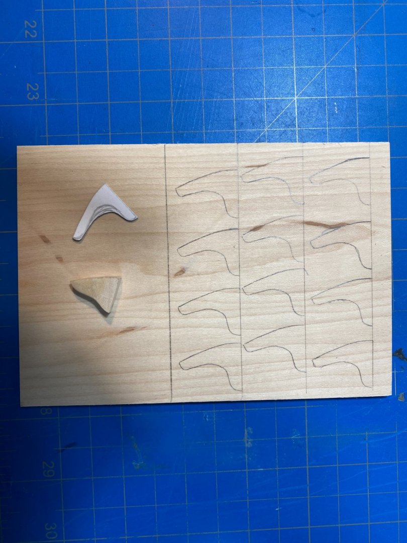
Progress! It has been over a month since I last posted, and Im glad to be able to report that Ive been able to make some headway, albeit at a much slower rate now that the post-COVID world is clawing back. In all Ive been able to get the outer planking and wales completed, gunports framed-in, the interior planking at the lower deck completed and treenailed, the gun deck beams made and simulated caulking done to a point. At this point Im not terribly convinced that I like the wales so hopefully time (or perhaps someone here) will point out if something is egregiously off. I opted to rip out and replace my lower deck hanging knees in favor of a more realistic shape and am much happier to have spent the time. They were really bothering me, and despite the pain-in-the-**** method of shaping them and fixing them after-the-fact I managed to do a reasonable job of it. (Left: Old coming out, Center: New template, with old knee removed, Right: Completed replacement) I also chose to give Chadb's method of using the putty for caulking a try as I like the effect he achieved and wanted to try something different. I did do a pretty extensive mock-up first to figure out the process. The result does look great, if perhaps somewhat out of scale.


-
NAIAD 1797 by Bitao - 1:60
Justin P. replied to Bitao's topic in - Build logs for subjects built 1751 - 1800
Your work is beautiful and unbelievably fast. Ill be following along with interest, as I did with your Young America. -
HMS Discovery 1789 by Don Case - 1:48
Justin P. replied to Don Case's topic in - Build logs for subjects built 1751 - 1800
I don't know which part of the book you are at, but I would imagine that given the amount of coastal exploration and surveying they were doing at the time, they probably didn't bother pulling up the boats. Leaving them tied to the ship to expedite short excursions was likely just a practical choice. -
I have the MF70 as pictured and would definitely be using it if I had to do what you are describing. I would partially wrap it in cling wrap and then use that engravers clay to mount it.
-
I agree with what everyone has said. @Chuck has a good explanation of his process in one of his many published tutorials and build logs - of which there are too many for me to dig through at the moment to find, but the essence is to thin out your paint and use many layers. My personal process is to first make sure I have a well sanded and sealed surface, and then to use a thin wash, almost 1:1 paint/water. I sand with fine sandpaper between each coat and apply until the color saturates to the desired level. I have used airbrushes in the past and do like their results, but find the apparatus and additional setup to be cumbersome and annoying.
-
I do basically the same thing. I make a dummy and tie to that, doing nearly all the work using that and a Quad-Hands.
-
Agreed! Looking more like it should now. Nice job identifying and correcting the problem.
-
Im wondering first if you used the templates provided in the kit for laying-out the lintels? That should have helped with some of the spacing. As well, the area at the bow seems to be sweeping upward where spacing should be uniform stern to bow. Cutting out the templates and comparing against your current state might help point to a few places where things are going wrong.
- 100 replies
-
- 1
-

-
- Syren
- Model Shipways
- (and 1 more)
-
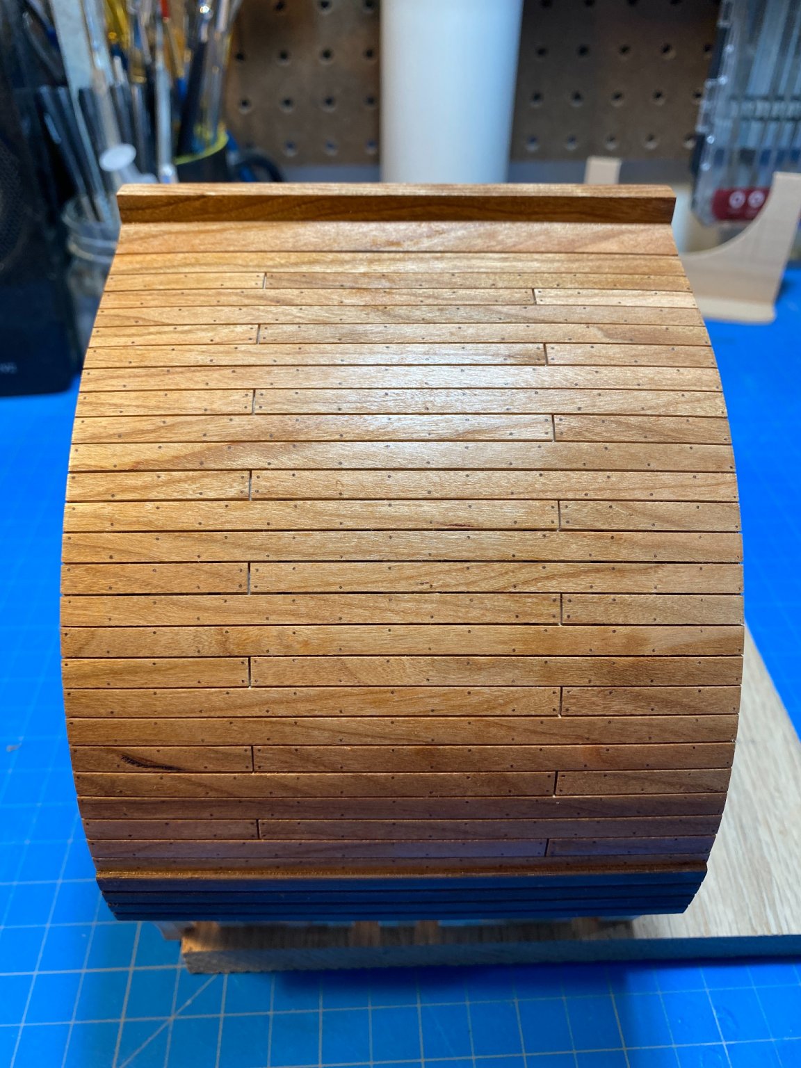
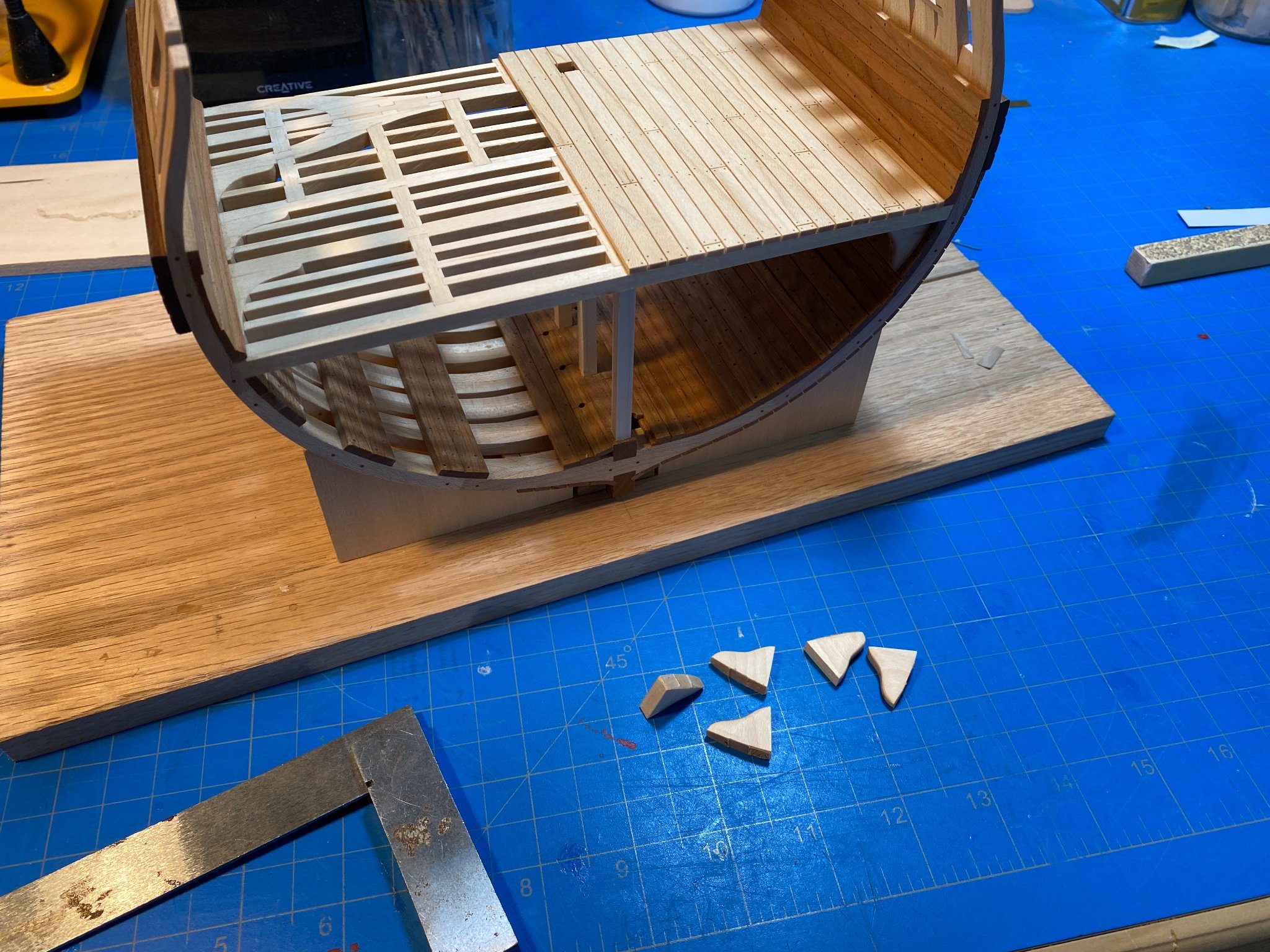
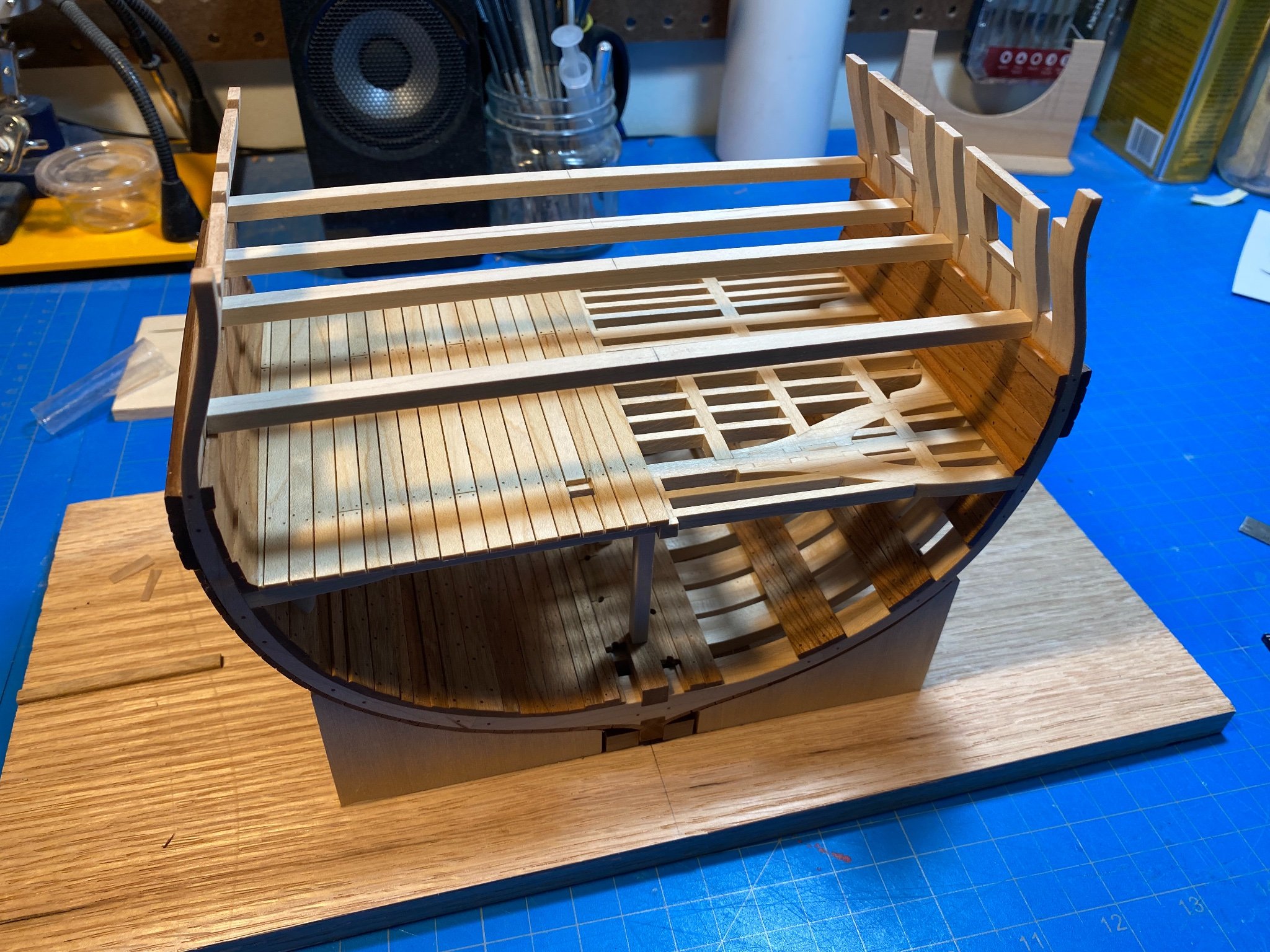
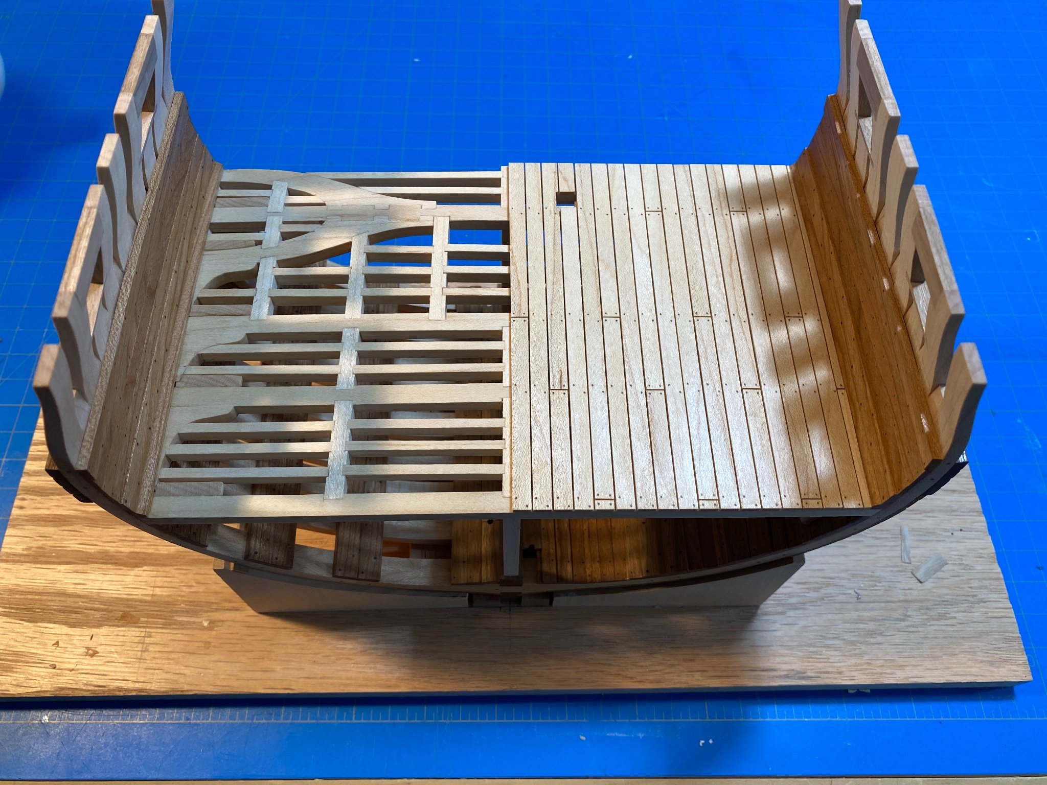
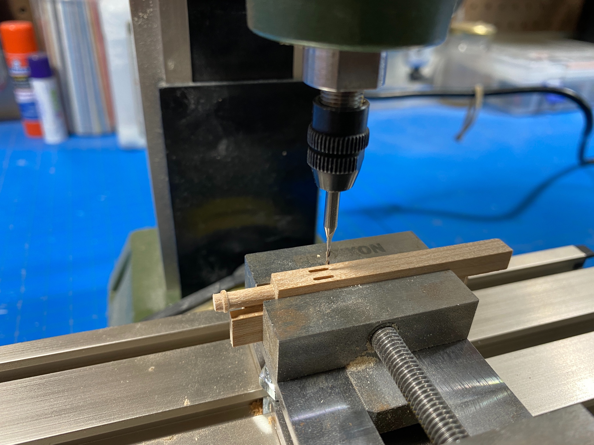
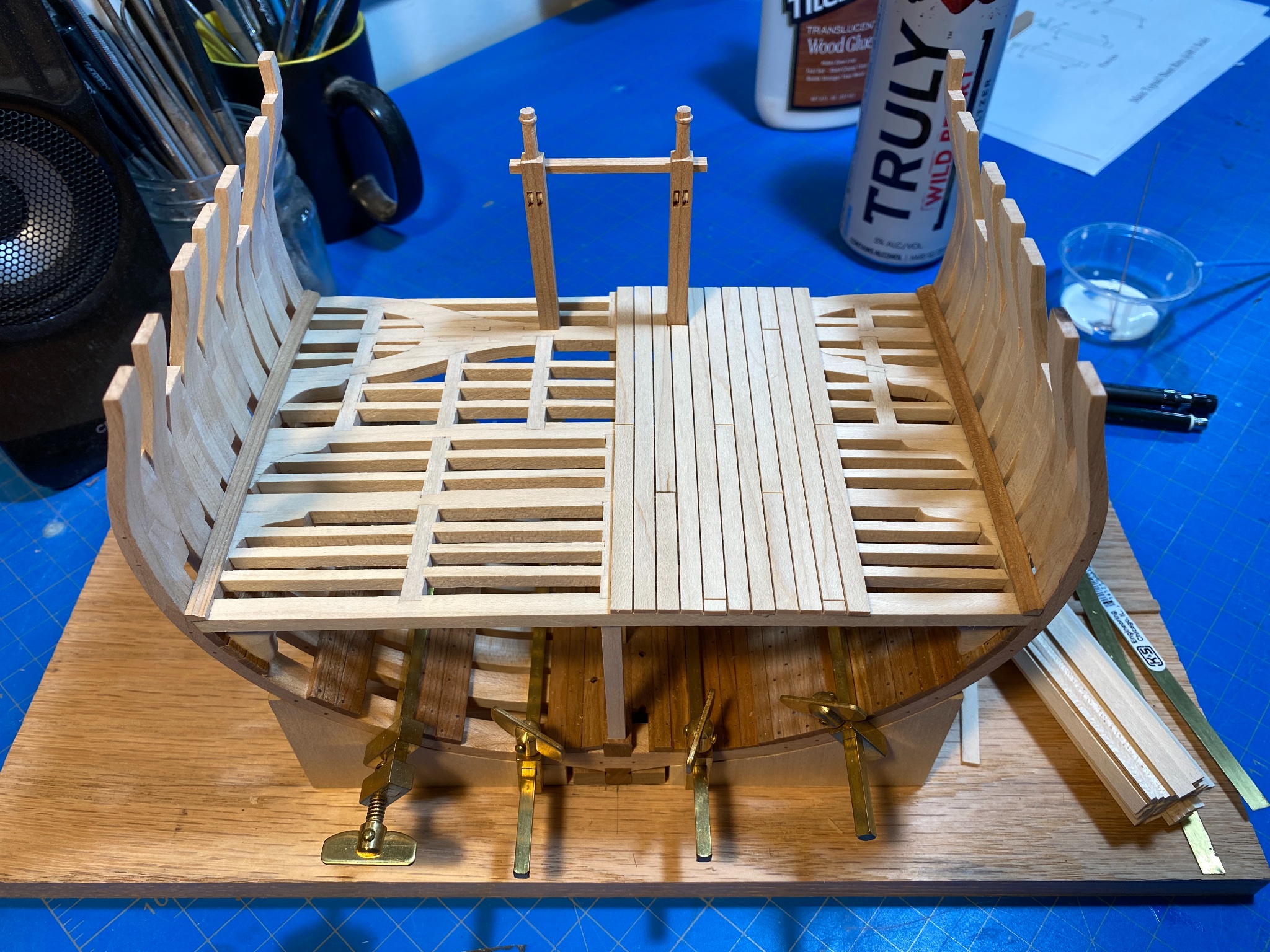
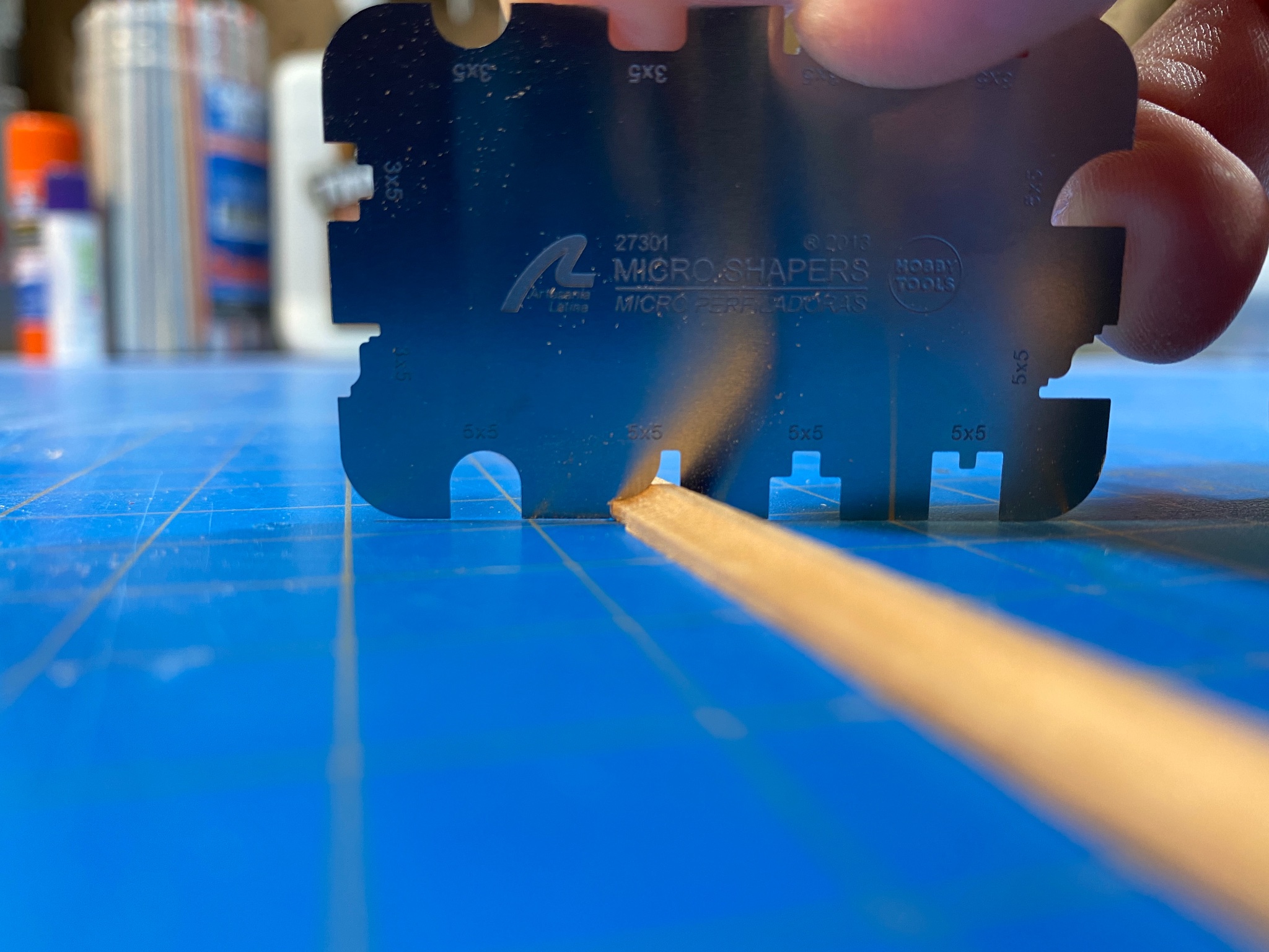
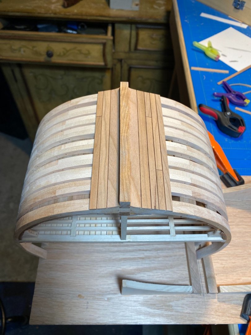
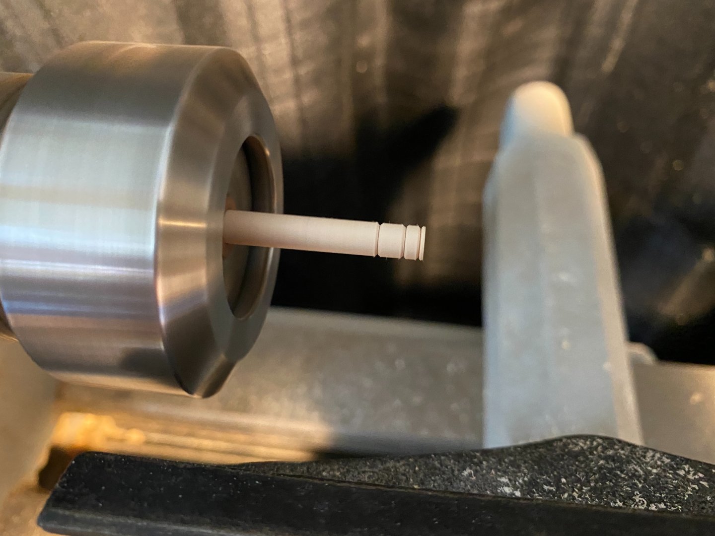
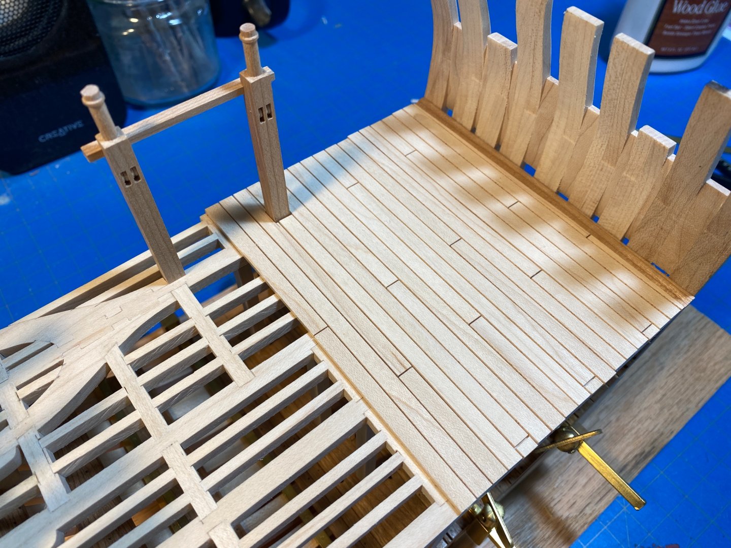
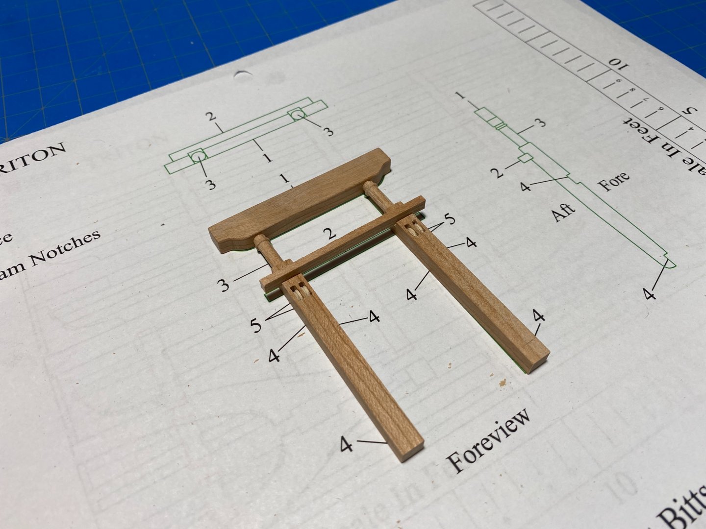
The next thing I started in on were the waterways. Fashioning the shape and style after details referenced by other builders and pursuing a few of the well-known sources I made a few prototypes using a micro-mill that just didn't really do the trick as well I wanted. So I pulled out one of the AL micro-scrapers I had and found a shape that actually matched what I was after pretty perfectly. I chose then to go ahead and make up the bitts and gallows as I wanted to be able to plank the lower deck up to the actual part rather than hope it works out later. I also chose to install the waterways at this stage as well, so I could pull a pattern off the subtle curvature of the install piece. This I imagined would better facilitate shaping the final deck plank (planked center outward). I turned the bitts from Cherry and then initially milled out the sheaves-ports before finishing them with a small file to square them up. I then turned the actual sheaves from Maple on a midi lathe. One fitted I used a cherry dowel to set them. I then tacked the bitts in place with their cross-piece using tiny amounts of glue and proceeded with planking. Thats where we are now. Im off to sail the Puget Sound for the next 10 days so that will be that for now.


-
Treenail holes
Justin P. replied to Don Case's topic in Building, Framing, Planking and plating a ships hull and deck
Agreed. Anything smaller than say, 1:48, and they become even more distracting (and difficult). I think though, they do add something to a model of a certain type. On most kits they end up looking additive and unnecessary and ultimately contribute to the "messiness" of the overall result. On others though, even if not meeting the correct historical aesthetic (circles v. rings) they can communicate a level of detail that without might leave an otherwise well made model looking a bit bland or incomplete. I feel that ultimately they require a subtlety and finesse that only a few possess and can execute truly well - too many and you are lost, too dark or not perfectly laid in straight lines, etc. I personally love them on the right model, but also admit to still learning the art of using them, let alone making or installing them. -
Hey Ainars, Can you share a bit more about your cannons and where/how you sourced or made them? They look great, and that surface character looks very real. Stunning work, and great finish on everything. What did you use?
-
Where can I find more info about the contest? I may give it a shot 🙂 I really hope you consider submitting, yours is so great and the photography so good! https://thenrg.org/contests
- 950 replies
-
- 1
-
-
- syren
- model shipways
- (and 1 more)
-
Congratulations! I hope you decide to enter her in the upcoming photo contest!
- 950 replies
-
- 2
-

-
-
- syren
- model shipways
- (and 1 more)
-
Sweet! So glad to see you getting right back to it! And glad to be the first to take a seat at the table. Looking forward to this.
-
Planking is definitely the major hill to climb when first starting out. I would get really worked up over it and did cause me to abandon some very early projects. What I learned is to use the right kind of glue (PVA) so you can back-track if needed more easily and to not let perfection get in the way of progress. The nice thing about kits like Syren is that the hull is partially painted and then coppered, which means you can be a little more forgiving of mistakes as they will be more hidden. Things like filler and sanding can make what looks to be terrible planking job much more acceptable to the eye. Obviously it is important to TRY and do it correctly as best you can (so you will get better), but I would not to agonize over details as you go. There is always a way to correct a problem, and we are all here to help out when you need it. Ive always felt that my best and most useful tool is MSW.
-
For a while there was a build log or post by @JerseyCity Frankie that many people referenced showing how he achieved this. It appears to be gone now. His were really good... If I remember correctly he used paper mache to create convex molds and then would set his sail material over the mold using some kind of finish (maybe Varnish or Shellac?) to get the sail material to hold its shape. I don't remember exactly how he did it, but it provided a great result. You might also try a search of the Forum, there are a few good threads on the subject:
-
Looks wonderful, especially the contrasting colors and finish.
-
NRG Capstan Project
Justin P. replied to tlevine's topic in - Build logs for subjects built 1751 - 1800
I figured this might be the case, the difference in these plans is negligible so wondered if there was some other reason. Thanks. -
NRG Capstan Project
Justin P. replied to tlevine's topic in - Build logs for subjects built 1751 - 1800
Thanks Kurt, I can understand the thinking here. I was really more curious about the choice to depict different parts in different scales in the plan sheets, and if there is a reason for this, or if its more an arbitrary choice. For anyone working with the same brain disadvantage as I am, I found that printing the plans at 100% on regular 81/2 x 11 paper gave a precise representation of 1:16 components. I then went back and printed the 1:1 plans separately at 75% and the resulting print was scaled to 1:16 accurately. Ive gone through and checked my printed sheets against my manual calculations and everything checks out. Of course its important to know your printer before relying on this for precise representation so double check everything against manual calculations for dimensions running in both directions. I know this stuff is probably automatic to most of you, but when numbers and language don't match my brain starts misfiring. For instance, 3/4 scale being represented as 1:16 but needing to be printed at 100% gets a bit confusing to me 😀. I feel like I can read all day about it and still not fully understand... thankfully my 7 year old gets it (and printers). -
Great idea with the mounts. I hope your recovery goes smoothly, and glad you were able to get in and get the problem sorted out. I know some folks who have been put on long waits with everything happening in the hospitals.
-
NRG Capstan Project
Justin P. replied to tlevine's topic in - Build logs for subjects built 1751 - 1800
Apologies if this question is better answered or more appropriate elsewhere... Ive never been completely confident in my understanding of scale, rescaling and plans use. Ive read through the instructions and have spent quite a lot of time looking through the plans. Im currently looking at converting some of the real dimensions on my plans and wondered why the majority of the relevant sheets are drawn to 1:16, while a couple other crucial components are drawn 1:1? The reason I ask is that in order to print, I need to separate the file into parts in order to print everything in one scale. If I were to try and rescale the 1:1 sheets to 1:16 in printing (so that all the required sheets for building are of the same scale), where would I go for good instruction on this? I suppose Im used to a certain way of building, where I can rely on a plan to act as a sort of template. If the intent is that I work out a way to construct the part by converting the dimensions alone, Im sure I could manage. It just seems easier to me to have drawn everything in a single scale, making rescaling less complicated. This is not a criticism at all of how these plans were produced, Im just curious about the scaling decisions - and then where I can go to learn how to rescale them accurately. Thanks in advance, really looking forward to build! -
Fantastic News! Thank you Chuck as you no doubt played some role in cultivating this new resource for the good of us all!