


Louie da fly
-
Posts
7,980 -
Joined
-
Last visited
Content Type
Profiles
Forums
Gallery
Events
Posts posted by Louie da fly
-
-
Yes, that makes sense. Perhaps only later did they start thinking of the extra masts in terms of providing extra power rather than just aid in steering. Certainly, as the fore and mizzen masts and sails got bigger the main course got smaller, providing a more balanced play of forces (though that's not necessarily cause and effect).
But then how did they mount those slim foremasts (apparently) on the stempost, without the mast just ripping out in the first big blow?
Steven
-
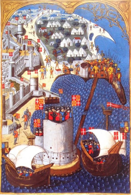
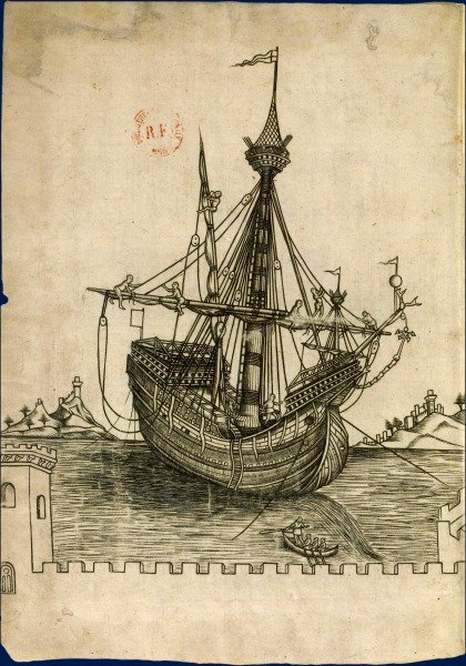
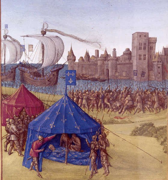
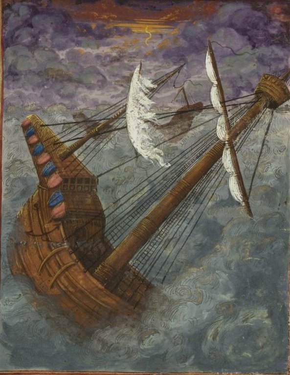
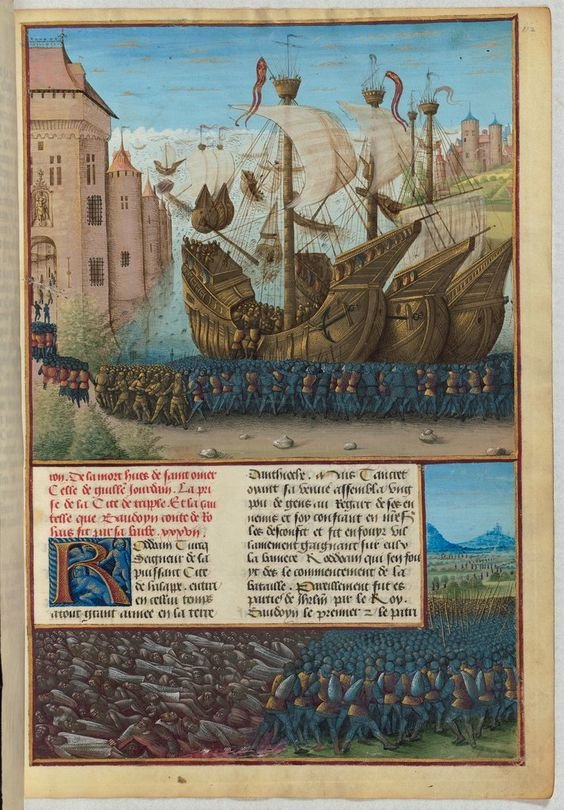
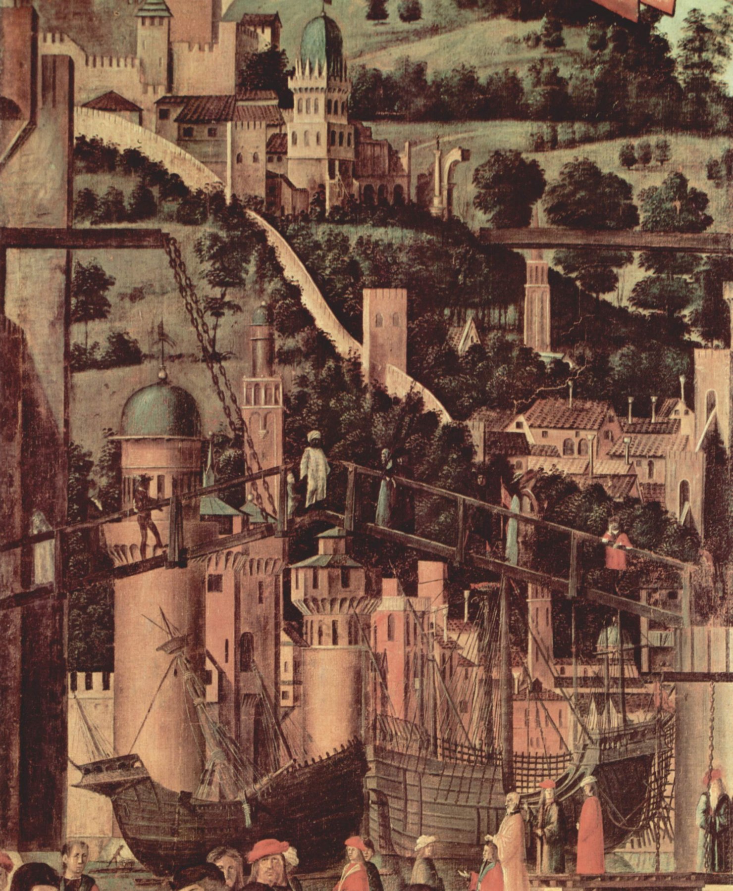
Well, perhaps you're right, Dick. I've collected quite a few contemporary pictures of single masted (and two-masted) "proto-carracks" and though as a general rule the single-masters seem to be somewhat more basic (with less superstructure, for example), there are plenty of exceptions - three-masters with simple superstructure and single-masters with the whole box and dice. And enough from this part of the century - and later - showing what are obviously meant to be cutting edge ships (such as the invasion fleet at Rhodes) with only a single mast. (Note, wherever I've been able, I've included the date and place of the picture in its title - you can see it by hovering the cursor over the picture).
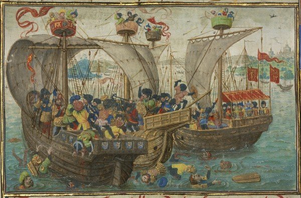

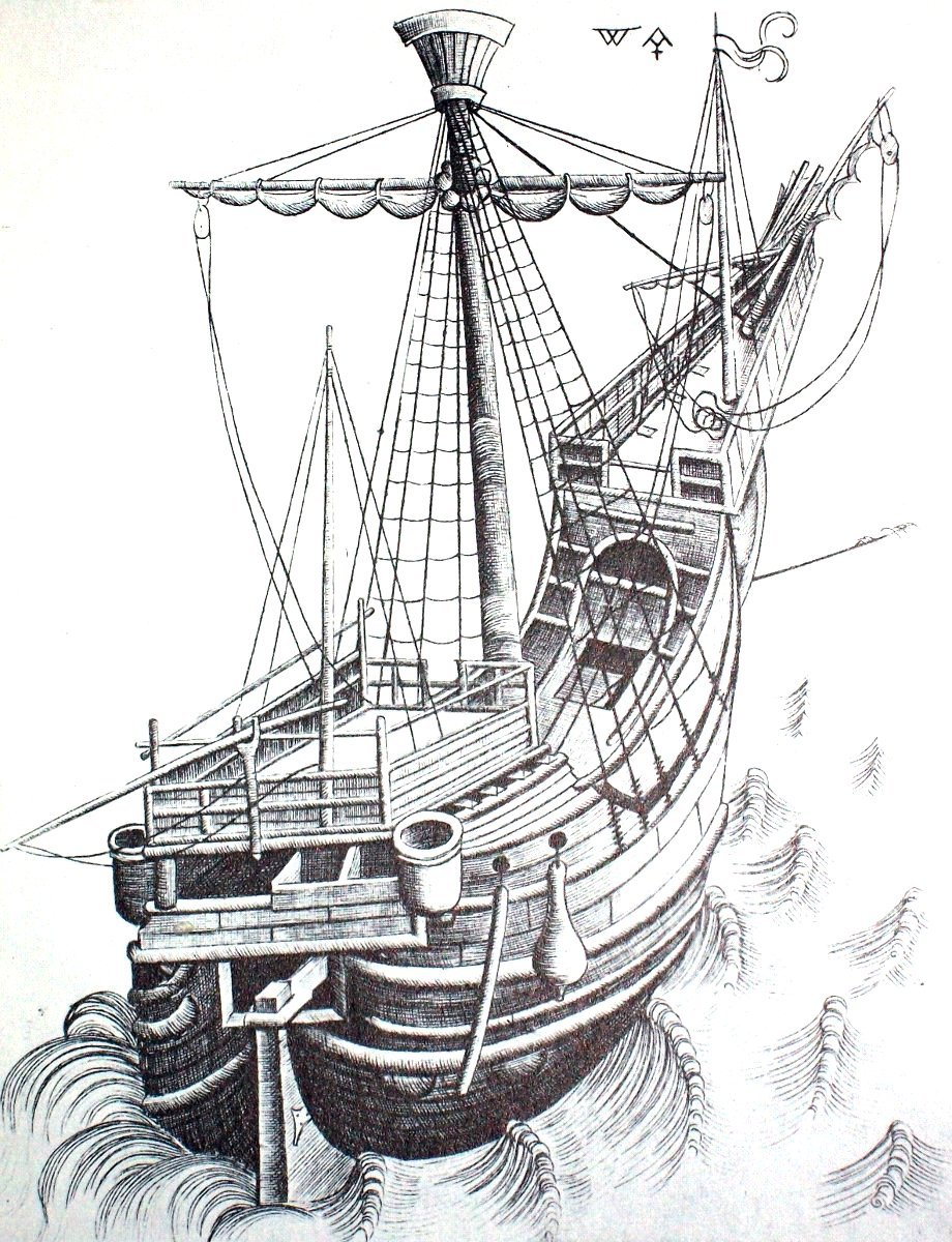
Regarding the impracticality of the foremast, I'm not sure where the problem lies, but it seems to me that many foremasts of the time were thin and short and seem to be a bit of an afterthought. As I think you mentioned earlier in this build log, some of them were very far forward - so far forward that they must have been founded on the stempost rather than the keel.
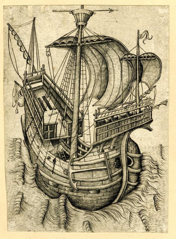


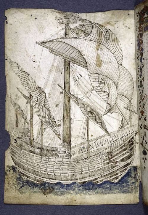
One at least is shown off-centre
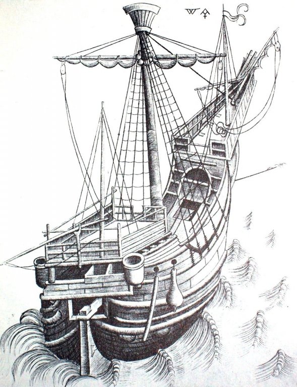
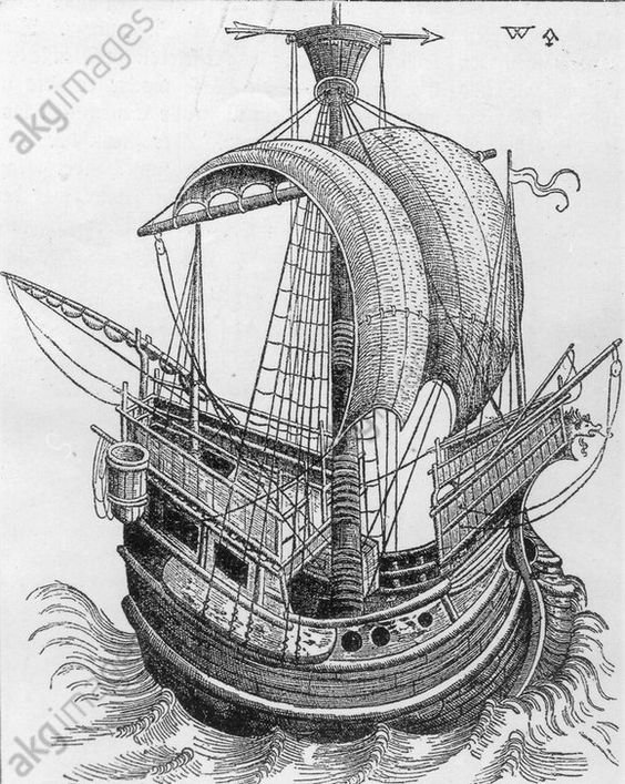
Others were thick and stumpy,
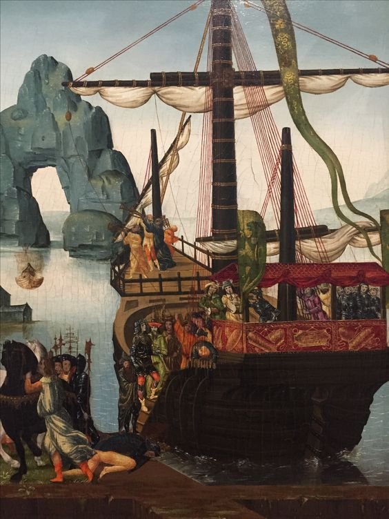
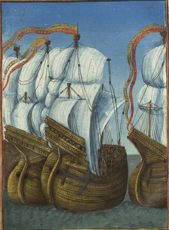
and yet others quite respectable masts in their own right.
.thumb.jpg.e0d965fb66b760f1765ea6d584dae570.jpg)
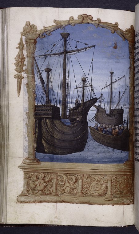
Obviously, the date of the representation is important - presumably the later the picture the more likely the ship is likely to have a foremast, and the more likely it is to be fairly substantial. And a lot of these pictures are several decades after your own representation. However, I think the further north you go, the more behind the times the ships are likely to be - Venice was at the cutting edge of ship design at the time. So a later picture from, say, Flanders, is likely to show what was common decades earlier in Venice.
However, consider also that in 1445 at the time of your model, there were quite a decent number of three masters (40% is still quite a few) and that it seems unlikely that the Doge of Venice, who could easily afford the maritime equivalent of a Rolls Royce would content himself with a Corolla, particularly at a time when one's prestige was so dependent on a conspicuous display of wealth.
Anyhow, this is all just for your consideration. I'm sure you'll work out something you're happy with and for us all to admire.
Steven
-
-
Coming along nicely, Robin.
Where would we be without balsa?
")
Steven
- EJ_L, Old Collingwood and Robin Lous
-
 3
3
-
That's beautiful work. What kind of wood was used?
Steven
- BANYAN, mtaylor, John Allen and 1 other
-
4
-
-
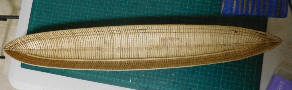
Thanks everybody for the likes and especially thanks Robin. (Of course I got the idea for the "waterline" from you.)
Steven
PS: My wife also thinks it looks like a basket.
-
-
Working on the keelson, stemson and sternson.
I've hedged my bets - the masts are supposed to be stepped into the keelson, but I still haven't decided whether I want one or two masts. So I worked out where the holes for the masts should be in a single and dual masted set-up, and bored holes for each and all.
From what I can see, the keelson in this model just isn't thick enough for a large enough hole for a mast step, so I'll probably fudge it and make a more substantial step to be sure the mast(s) are properly supported. It'll all be invisible below decks anyway, so I'm not going to get too concerned. I'd rather have the masts properly secured than have an accurate (but inadequate) step which nobody can see. Interestingly, the contemporary Byzantine texts talk about ships' masts unstepping themselves in a heavy blow, and maybe now I can see why.
I didn't have a long enough straight enough piece of wood for the full keelson so I've scarphed two pieces together, and also made scarph joints for the stemson and sternson. I think I'm getting better at scarph joints . . .
Here they are dry fitted to each other:

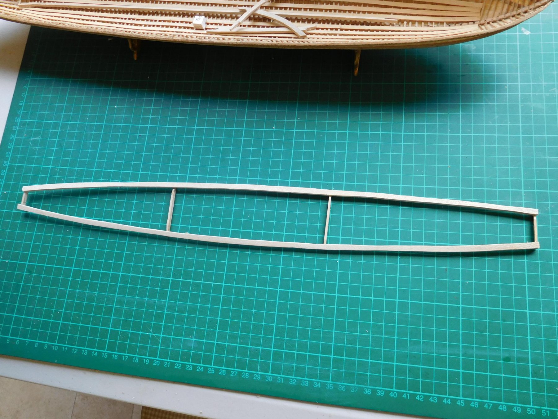
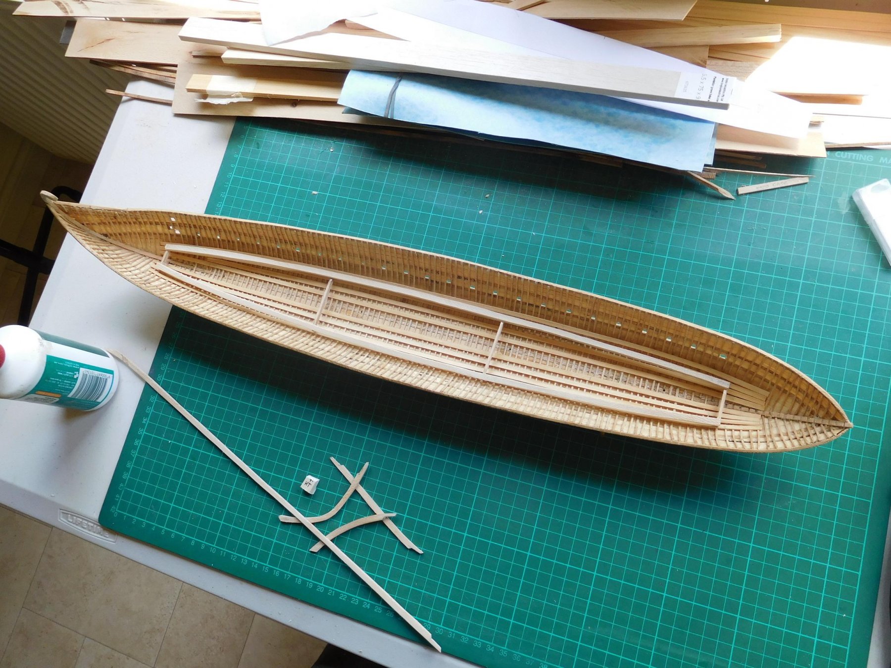
And some progress on the support frame for the lower bank of oars. I've spent a lot of time agonising about how to do this, and it looks like I've come up with an answer that will work.
A frame that follows the curve of the hull, far enough inboard of the sides to allow for the inboard section of the oar-looms.

To get the vertical angle right I made up a temporary support at water level and rested the oar blade on it. This then determines how high the oar handles have to be, and so where the top of the frame should be. Once I figured that out I made temporary supports out of balsa to support the oars at the right height, and these will be replaced in due course with a permanent frame.


I also angled the sides of the frame so the oars would rest along its surface, rather than just touch at a point. Viewed end-on the curve isn't as smooth as I might like it to be, but this will all be invisible - this frame is purely functional - it never existed on the real ship.
The idea is for the outboard part of the oars to be properly oar-shaped, but inboard they'll be flat in section and each one pinned to the frame with a small brass pin which will allow them all to swivel, so I can move the frame forward and aft till I get the horizontal angle right.
I've cunningly decided to have the oars at the end of their stroke - that's to make it easier for me to make the upper oarsmen, as then their arms will be right up against their chests rather than extended, and that will make it easier to carve and cast them.
Steven
-
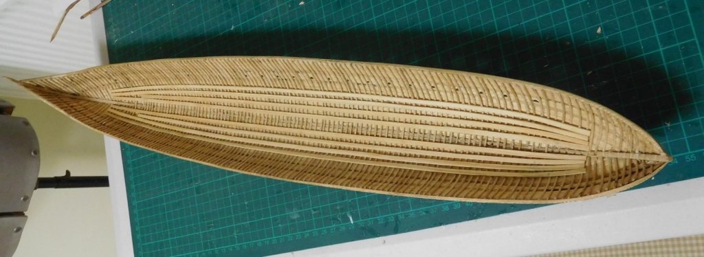
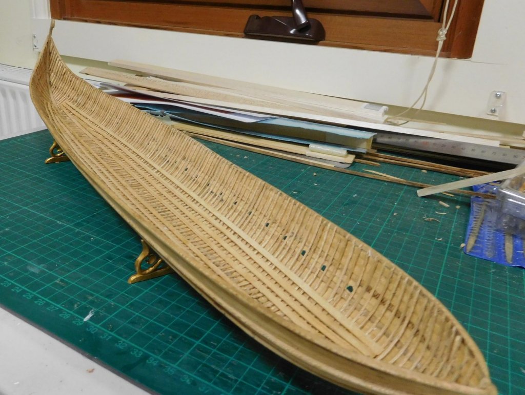
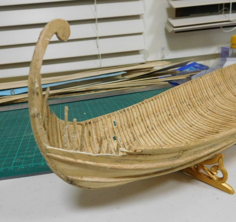
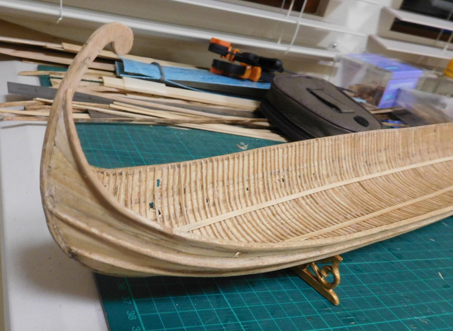
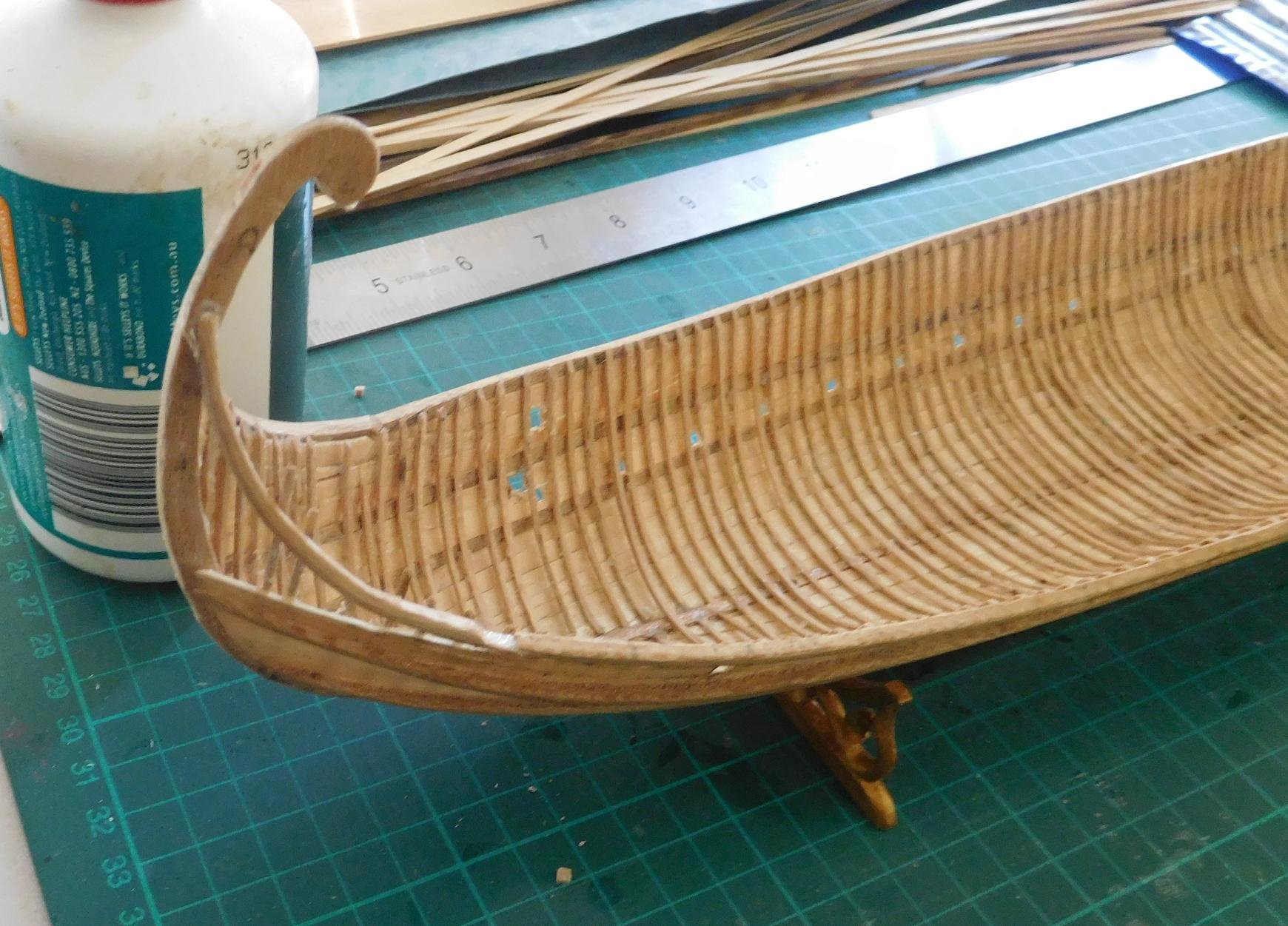
The repairs to the planking are now complete:

I think I'll extend the gunwale up to the pencil line on the tail, which is how it was before the disaster. I think it will look better.
And the stringers are all in place. They look quite a bit better than I'd expected.
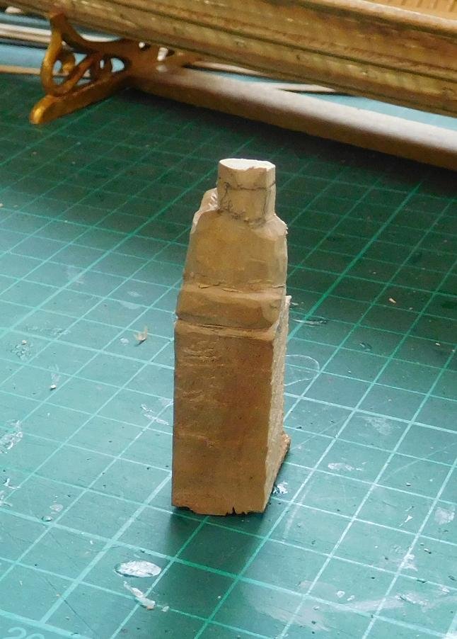
And I've been back to the figure carving in between times. This is the VIP passenger - Emperor Alexios Comnenos, who I chose because he was the one who initiated the use of fearsome animal heads to shroud the "business end" of the Greek Fire projectors, adding to the shock and awe.
Early stage -roughing out, which I call the Megatron stage - (look at his face)
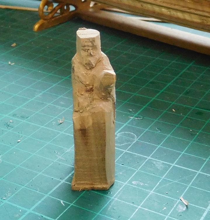

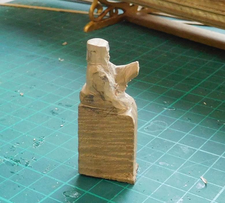
He's sitting on a "portable throne" with a bolster behind him, which appears over and over again in contemporary representations. They were gilded and very ornate. Here is a contemporary picture of him, with Christ sitting a throne of this type, though the one I'm making has four fairly hefty legs - also a common feature. Hmm, I'll have to make a footstool as well.
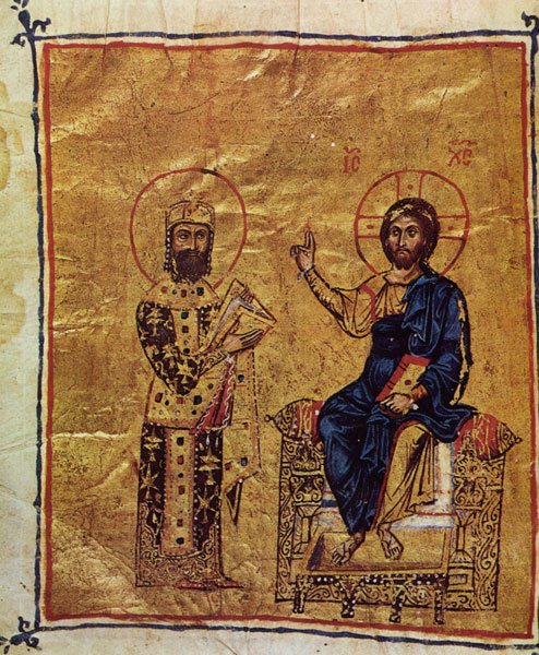
I'll try to reproduce that as best I can at this scale.
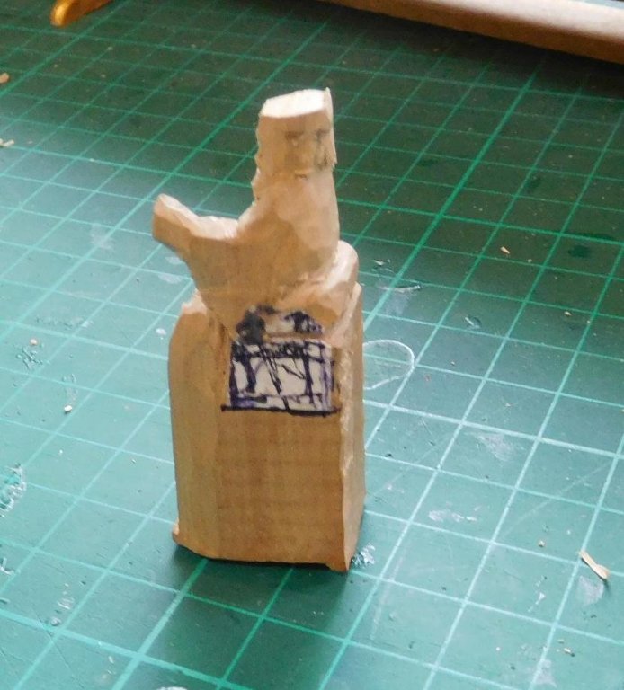
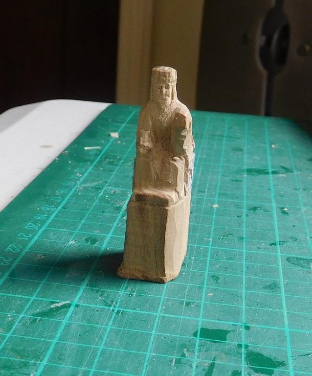
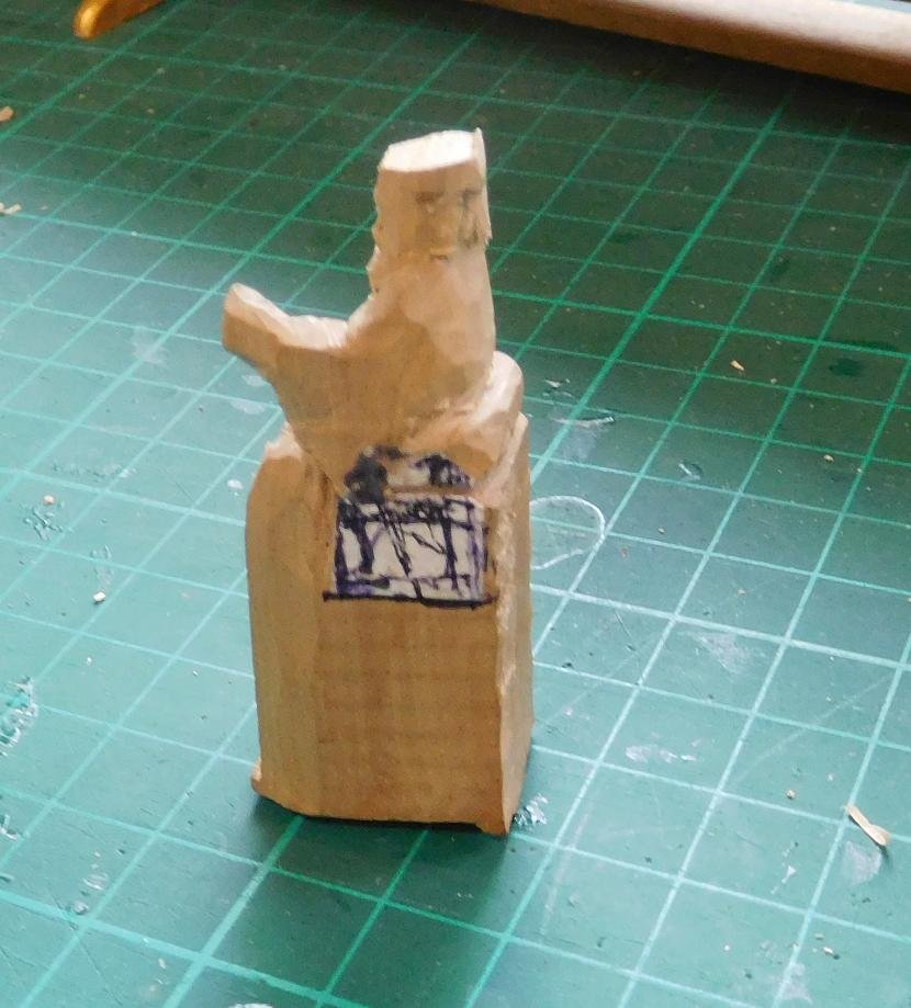
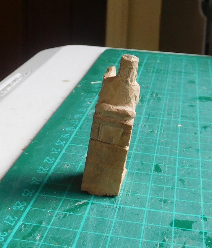
Next stage - finer shaping
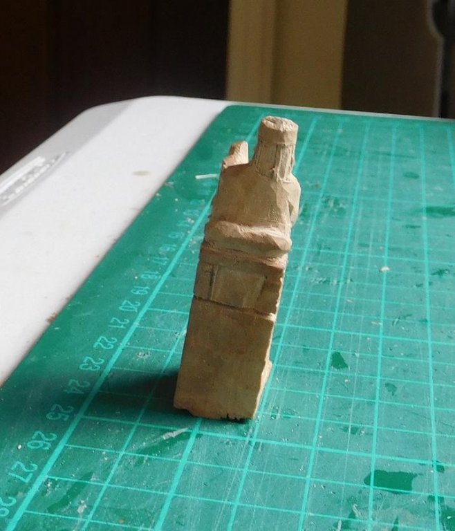
Next stage - nearing completion
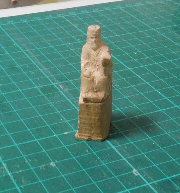
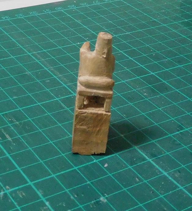
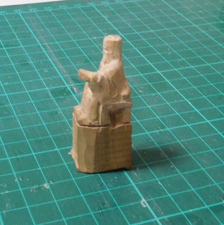
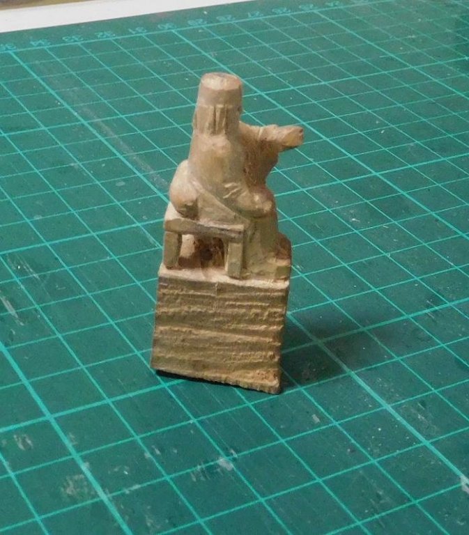
Still quite a bit to do on him - smoothing off and trimming etc. And of course painting. My faces are getting better, but I just haven't been able to capture the slightly rogueish expression on his face.
My next project will be to make the framing to support the oars of the lower bank below deck level, standing in place of the oarsmen themselves.
Steven
-
Hi Michael,
Beautiful work. The march of archaeological progress can be a real problem - it can turn what we "knew" on its head. A model based on this can only be accurate to the best knowledge to date - subject to further discoveries. I am in awe of anyone who completes a ship model as complex as this, and you've done an amazing job of her.
By the way, regarding the Viking shields, you might be interested in this link. The Gokstad ship's shields alternated - one plain black and one plain yellow shield, then black, yellow etc. The black was probably charcoal with some kind of binding substance (I experimented back in the day with animal fat - it works well, but attracts files like you wouldn't believe), and the yellow is though to have been arsenic sulphide. Unfortunately, conservation techniques when she was discovered were not what they are now, and no trace of the pigment survives.
Steven
- CaptainSteve, John Allen, EJ_L and 2 others
-
5
-
SUCH a pretty ship. I went on board the replica while she was still a-building, and still have the little oak off-cut with her name burnt into it with a branding iron.
I'll be following the build with interest.
Steven
-
Just guessing here, but I think it would to a certain degree depend on the Captain's finances - a well-off captain would probably provide his own furniture and it would most likely be in the fashion of the day (there should be lots of images on the Net if you do a google search), though unless he was very wealthy, I'd expect it to be a relatively plain version of that style. If he wasn't well-off, the ship's carpenter would probably make it for him and it would be VERY plain.
Steven
- mtaylor, John Allen and druxey
-
3
-
You can be justly proud of this model.
It's been an inspirational journey and I've learned a lot which I might be able to put to use in my own build.
Steven
- Robin Lous, CaptainSteve, cog and 2 others
-
5
-
On 10/15/2017 at 12:13 AM, Backer said:
I find this a boring job. So, we do this work occasionally between the military models production.
About 600 holes drilled.
I don't know if "boring" in your language also means "drilling" as it does in English. Or is it just a wonderful coincidence?

Steven
-
-
Thanks, Backer, and thanks to everyone for the comments and "likes".
Yes, I know enough organic chemistry (did a single semester at university and never went on) to know these are two very different animals. Isopropanol is a considerably bigger molecule. I don't know how that would affect the two substances' ability to dissolve white glue. I might experiment with "metho" (methylated spirits) on some waste pieces and see what happens. You can get it at the supermarket, it's cheap and doesn't have colouring added.
Steven
-
A really interesting solution to the problem of mounting oars. I've been pondering the same problem myself for some time and I'm taking inspiration from yours. The dromons had the leather sleeves as well, and I was thinking of using aluminium foil from the kitchen for both those and for the flags when the ship is finished. I don't know how it would compare with yours.
Looking very good, and I love your case as well - shows the model off to its best advantage.
Steven
- Old Collingwood, Robin Lous, cog and 1 other
-
4
-
-
My bad. It appears Hearns only have OO HO and N gauge (1:87, 1:76 and 1:148).
But there are two worthwhile looking modelling shops in Ballarat which might be worth a phone call - Collector Models in Canadian and Harpers in Harold St Wendouree. There's also Toyworld in Howitt St and Handcrafts and Collectable Models in Sturt St, though they don't seem as likely.
And it still might be worth contacting Hearns in case they can get O gauge figures in for you.
But maybe the Net is your best bet. There are plenty of overseas suppliers if you do a search for O gauge Victorian figures.
Steven
-
Glad the book was useful to you. I was impressed by how much information the author had managed to pack into such a small book. And for a change, it all seemed relevant, rather than being padded out with a lot of bumf and waffle.
Steven
- cog, John Allen, popeye the sailor and 2 others
-
5
-
Thanks, Druxey. If I do something like that again I probably will cut the pieces to shape. Bending is too uncertain. But I wanted to try it out - hubris, I suppose.
I've kept an eye out for those plastic-covered clamps you asked about. No joy so far, but I'll keep looking.
By the way, I looked up "rubbing alcohol" and apparently what it is depends on where you are - in the US iso-propyl alcohol is called rubbing alcohol. Elsewhere (as in the UK) it's ethanol ("drinking" alcohol) with about 5% methanol (wood alcohol) to make it undrinkable - otherwise known as methylated spirits. Best served cold from the fridge
. Which one is it you use to get glue off?
Regards,
Steven
-
Hearns hobby shop under the arches at Flinders St Station in Melbourne - down Flinders St walking away from Swanston St. I think it's still there, and might have the figures you need, intended for model railways. As Kurt says, "O" gauge is 1:48 - close enough to 1:50.
Maybe you could phone them and find out (saves you a trip to Melbourne if they don't).
Steven
-
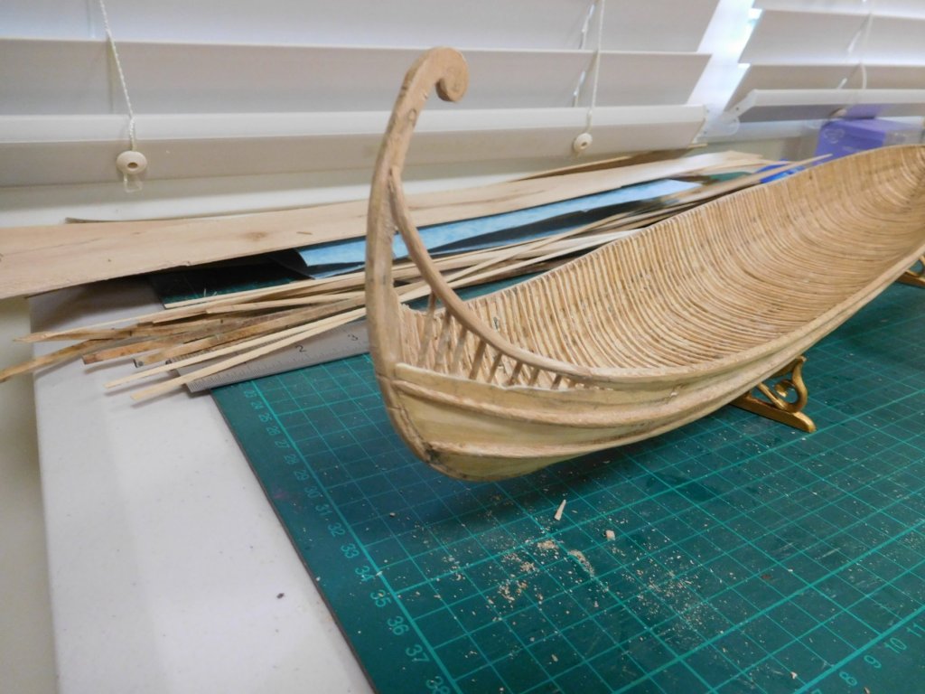
I’ve been away for a while – life’s been getting in the way. But I haven’t been idle; there’s been slow but steady progress, though a little erratic.
I put in place the through-beams for the steering oars and began on the support structure . . .

And then - DISASTER! The extensions to the gunwales that formed the tail of the ship had been shaped by heat bending, and when I put them on I didn’t realise they were exerting a sideways force on the sternpost. On a routine inspection I discovered they’d pushed the sternpost into a quite dramatic curve to starboard - and the tail planking was following the off-centre curve.
It took a week to decide whether I should correct it, with the chance of completely stuffing up the whole ship – the frames and planks are very delicate - or leave it as it was and have it sneer at me for the rest of my life.
In the end I took my courage in both hands and started pulling it to bits – with horrible memories of what happened when I decided to re-do the Great Harry model – it’s still waiting for me to rescue it once I’ve finished this one.
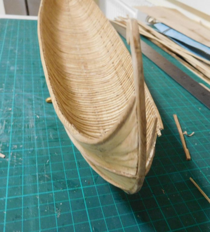
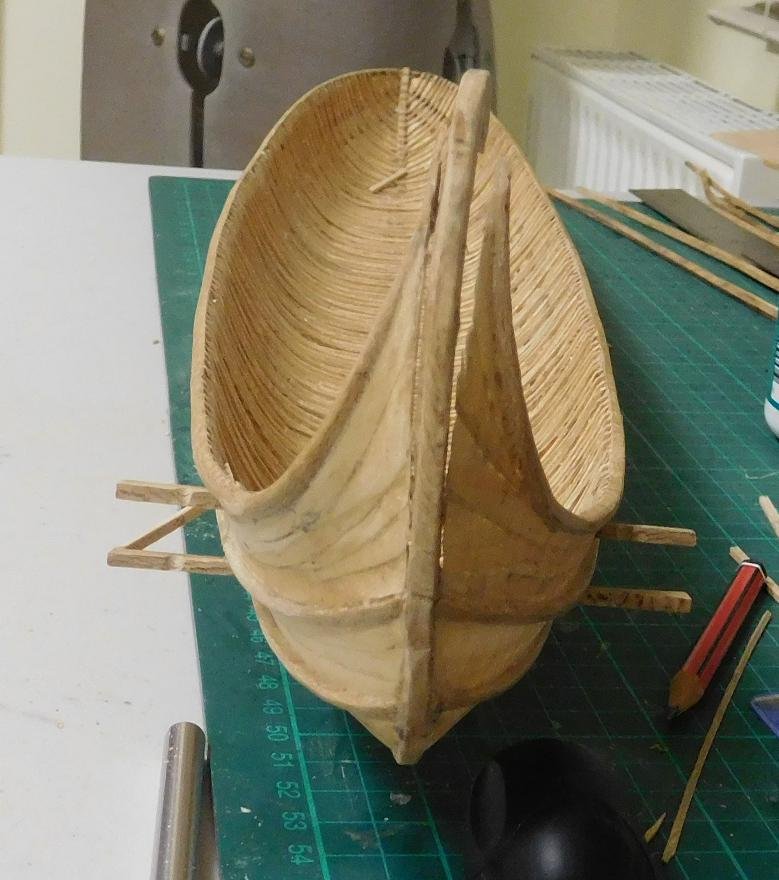
I should have taken a “before” photo to show how bad it was. But I at least got some directly after I’d cut both sides away from the sternpost, which gives a fair idea.
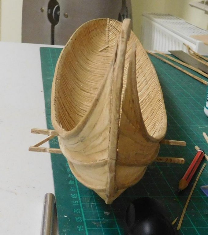

I’d thought I’d have to put the ship back on the plug to have a stable base for the repairs, so I removed the through-beams and the partly completed steering structure as well. It turned out I didn’t need to use the plug, but removing the through-beams has made it easier to put in the stringers (see below), so it wasn’t a total loss.
Fortunately the port side wasn’t too bad, and the sternpost came almost back to its correct shape once it was cut free. But I had to take off quite a bit of the planking on the starboard side.
And the “tail” of the starboard gunwale.

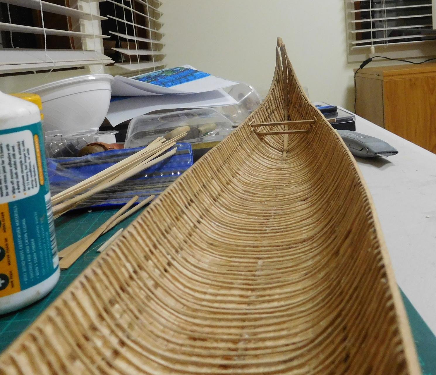
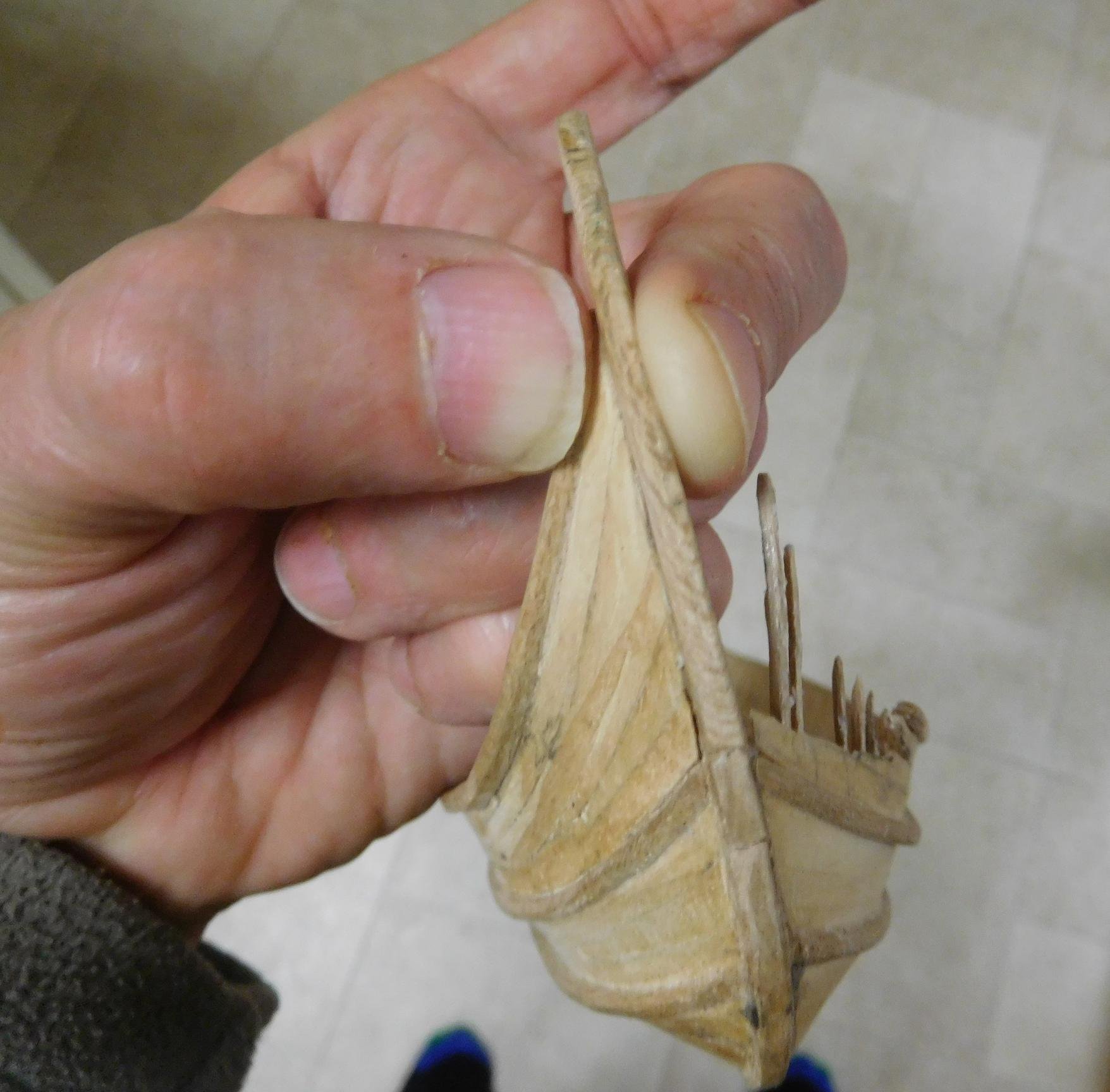
It turned out that the residual bending in the port gunwale and the sternpost cancelled each other out, and i was able to bring it all back into square by squeezing them together. I didn't have a suitable clamp so while the glue dried I just held them together with my fingers.

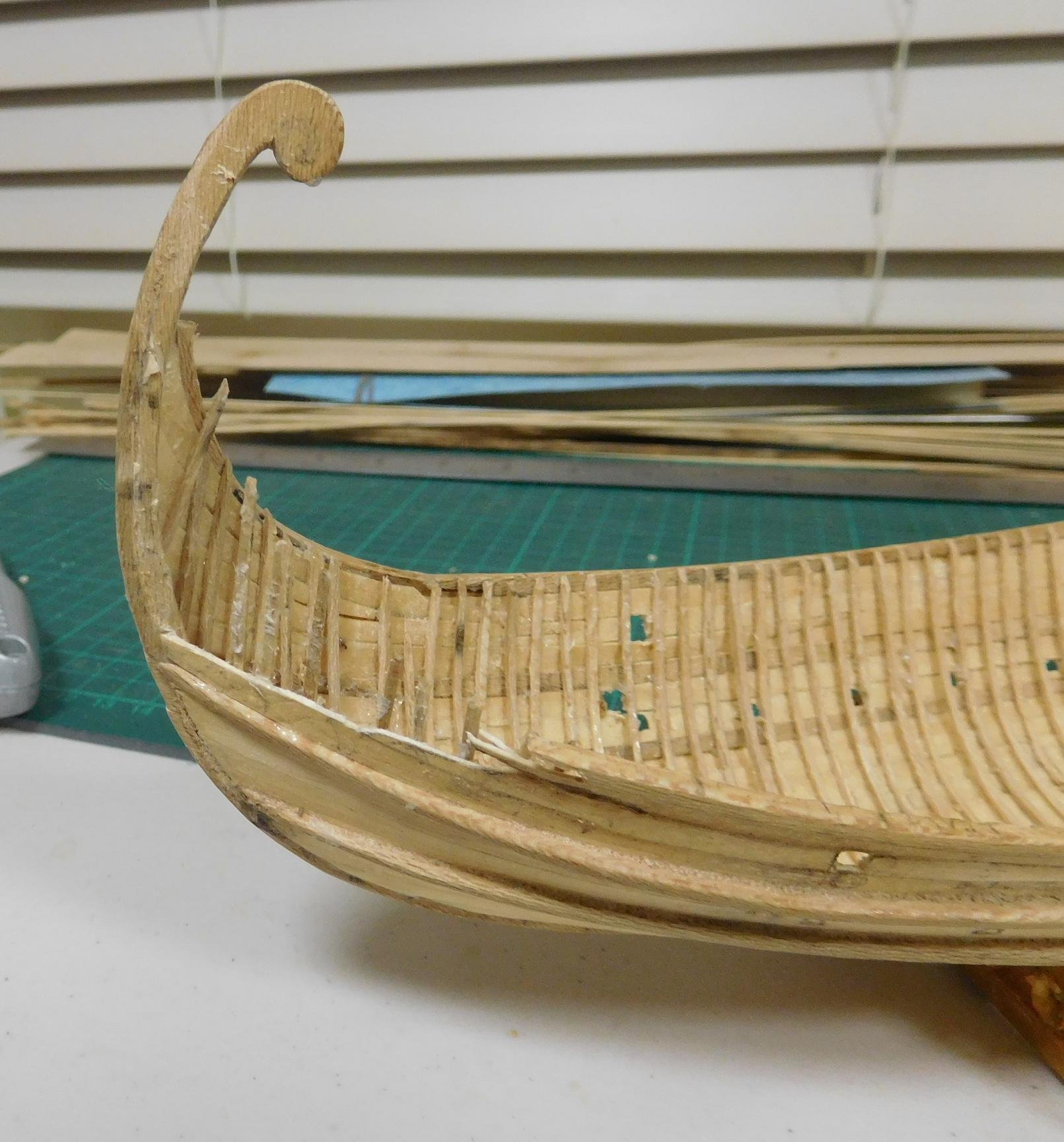
And it's now about as straight as it can be. A tiny bend in the head of the sternpost, but it's almost invisible and I've decided I can live with it.
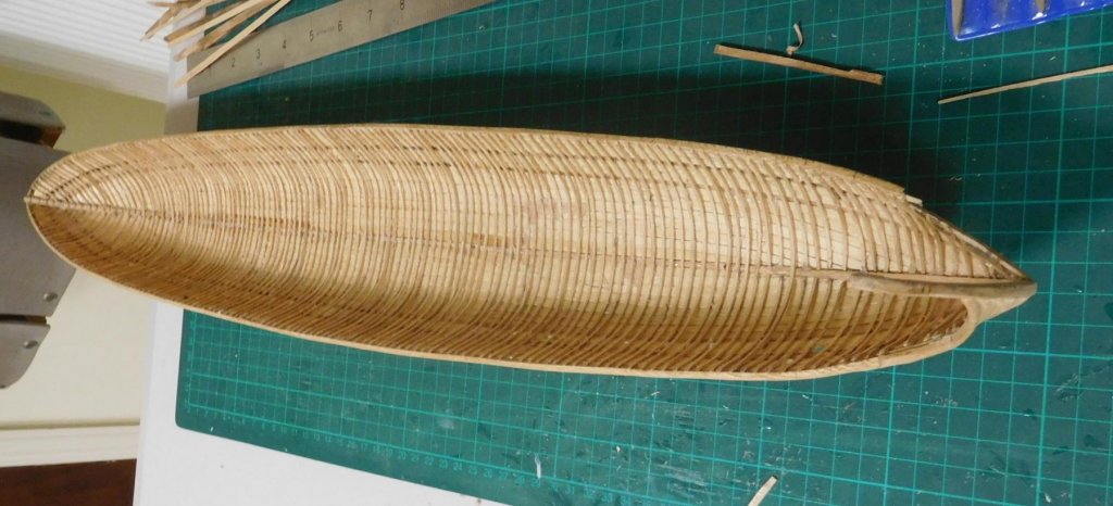
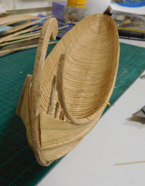
I’d been worried I’d have to make a new pair of “tails”, but I was able to re-use them with a minimal amount of tweaking, and re-position them so they didn’t push the sternpost sideways. I’m pretty happy with it now - it’s nice and straight and as the off-centre forces have been removed I’m satisfied it won’t happen again. But the starboard “tail” was now about 3mm (1/8”) too short,

and I had to use filler to make it good at each end.
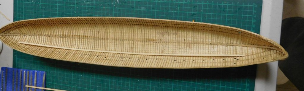
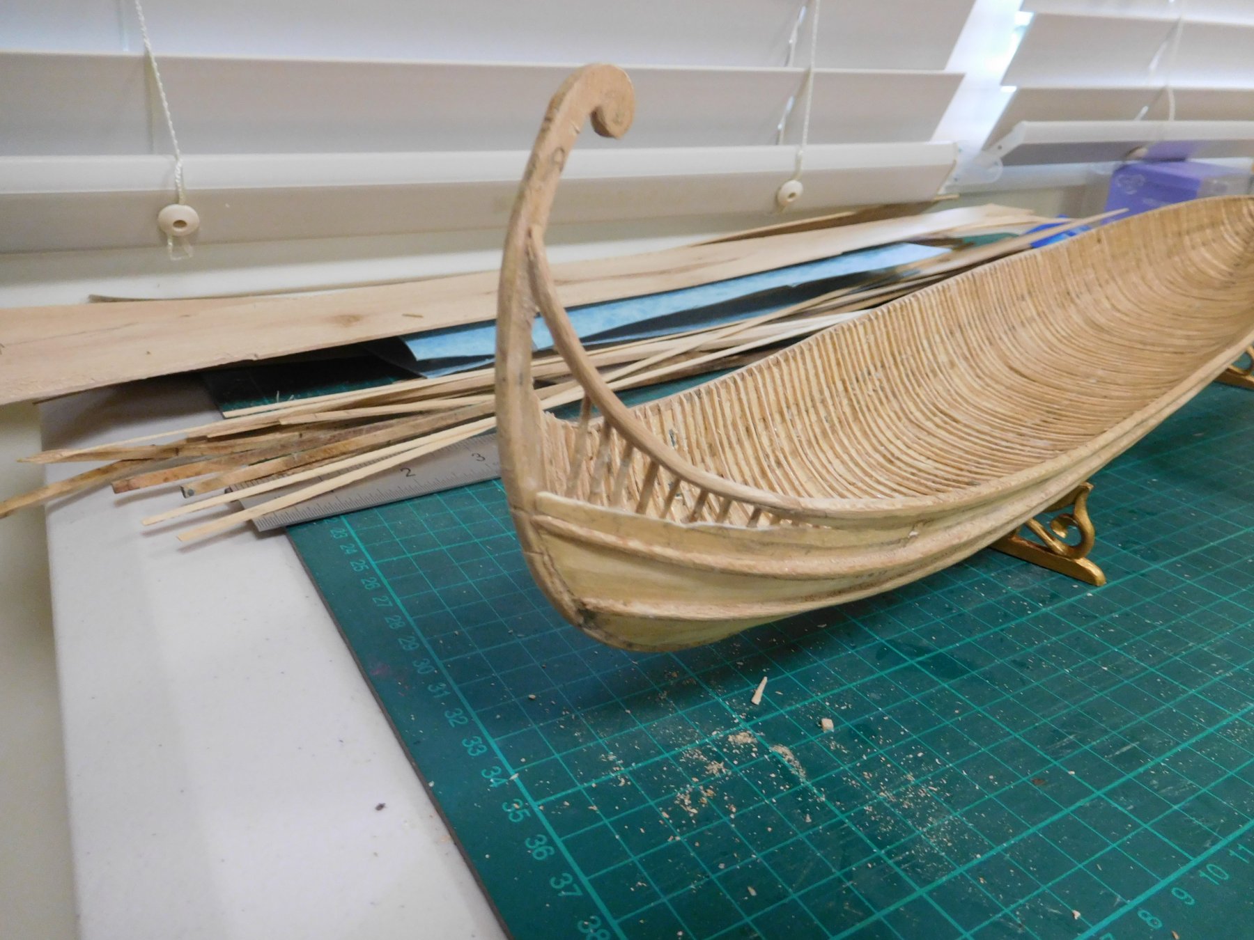
While under repair it looked pretty ghastly,
but I’ve finally got it to a point where it only needs a bit of planking and it’ll be right as rain.
Another learning experience. Sigh.
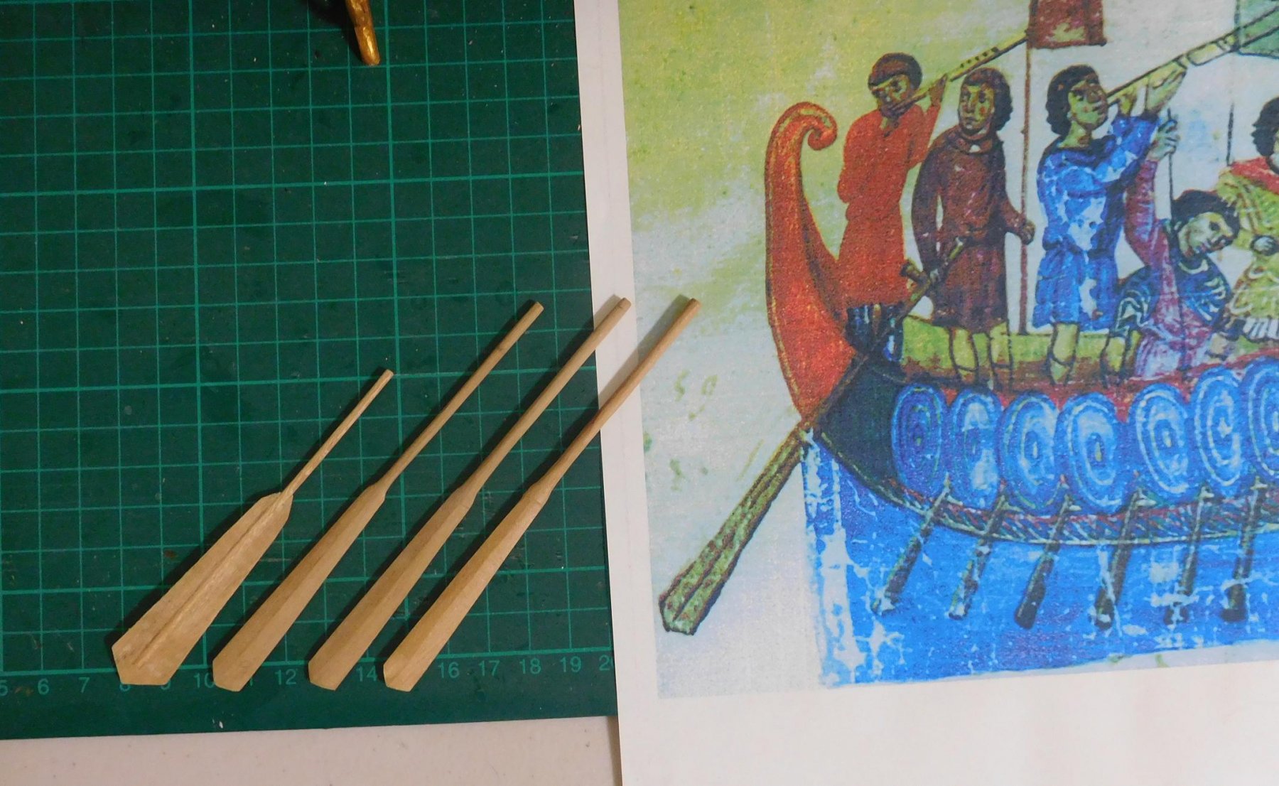
By the way, having finalised the steersmen’s positions, I realised the handles of the steering oars were way too short. Serves me right for making them too early. As I was going to have to re-jig them, I thought I’d have another look at the 11th century picture I got the design from. Not good, I’m afraid. The rudders I’d made didn’t look much like the original at all.
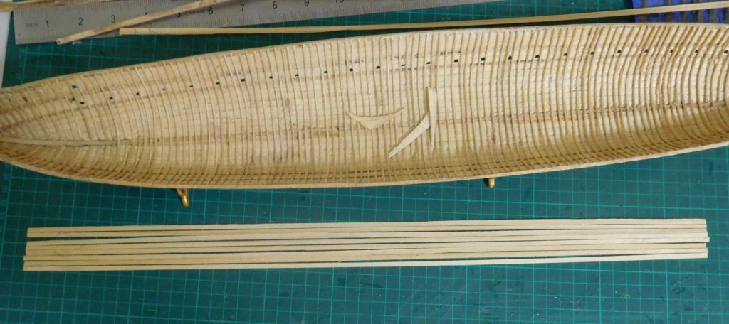
So I might as well be making completely new ones. Below are the steering oars, with the contemporary picture for comparison – from the left, one of the original pair; then the first new one, carved out of pear wood (which I discarded because although the shaft was the same thickness as in the picture, it looked too thin for the forces involved in steering a ship of this size); and the last two are my final version. I still have to put the tillers (visible in the picture) on them.

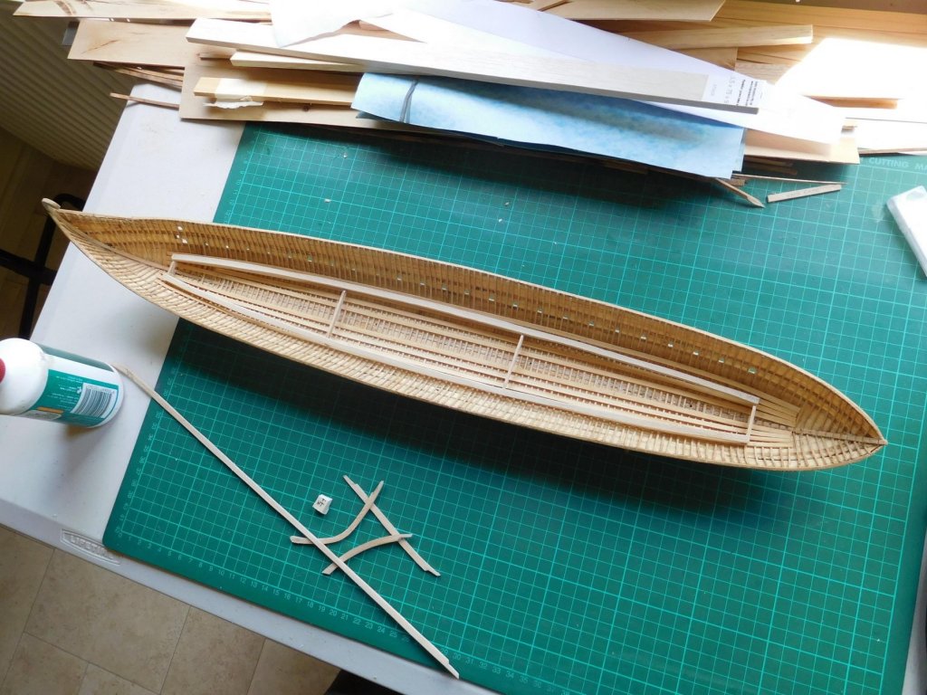
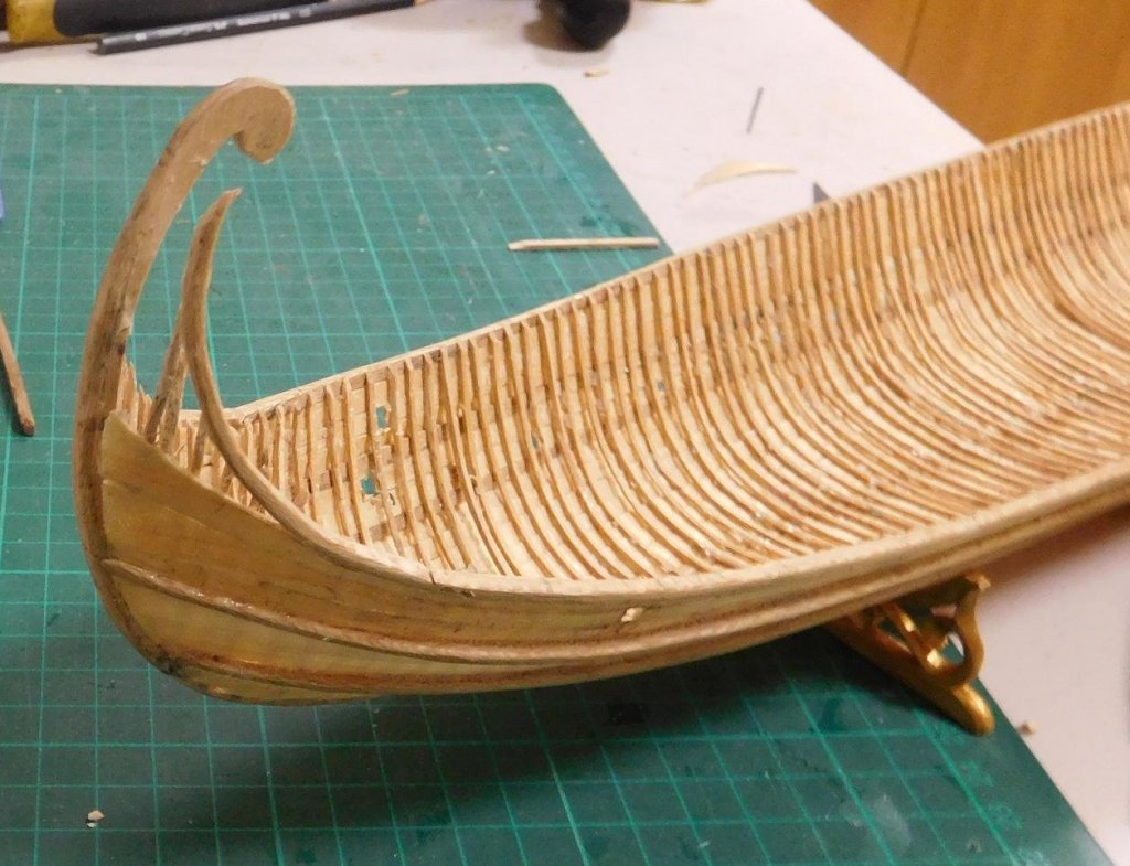
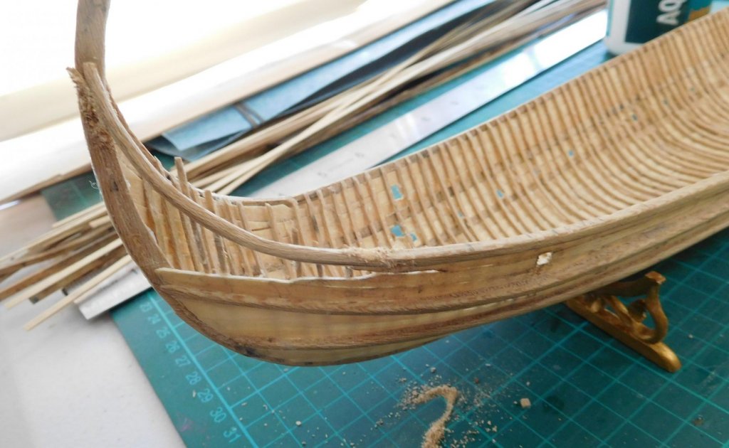
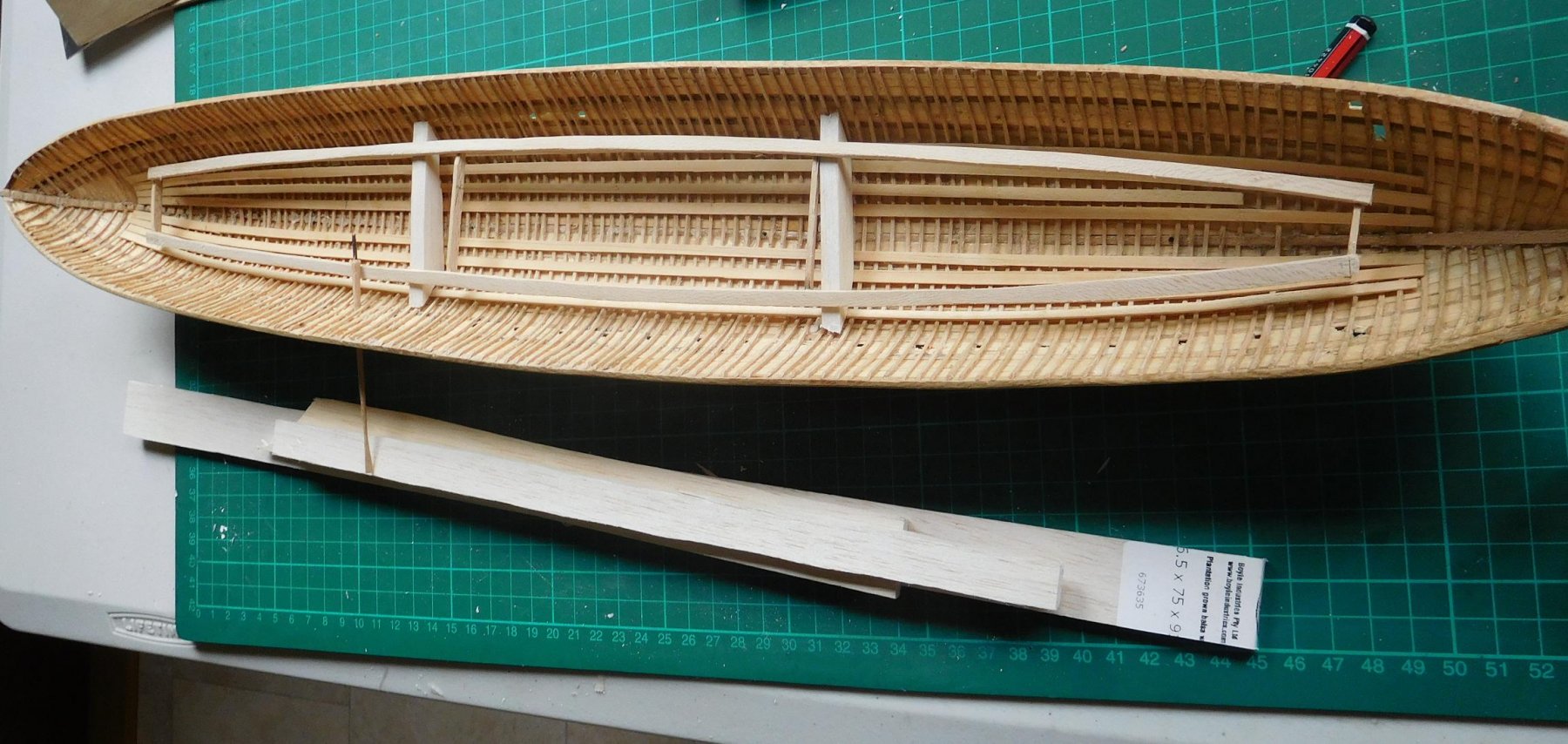
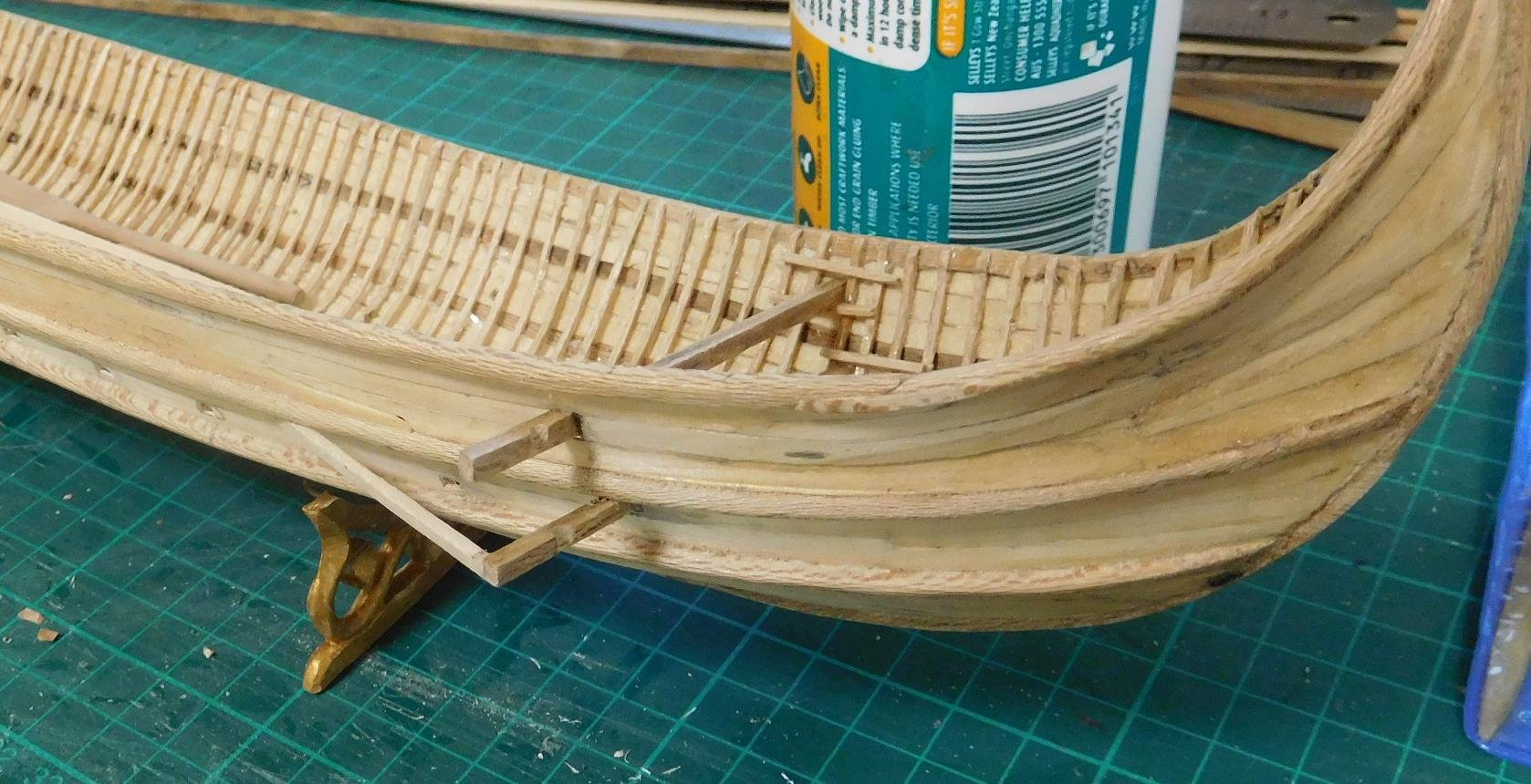
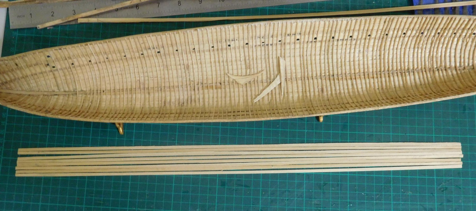
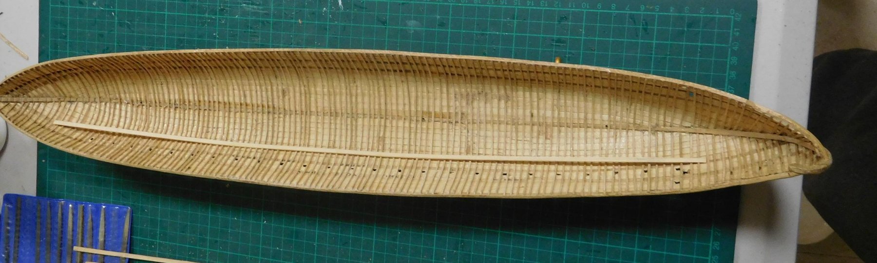
I’ve also made a bunch of stringers, based on those found on one of the Yenikapi galleys. Only two of the galleys found had stringers. One had only a single pair, each made from half a youngish tree split down the middle, and placed face down at the turn of the bilge. The other had four stringers each side of the keel, made of planks the same thickness as the strakes of the ship (about 25-30mm, or one inch), and 150mm (6”) wide. Though the first configuration did seem attractive, I decided to follow the second. Here they are:
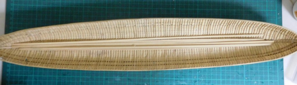
And here is the first one in place at the turn of the bilge. There’ll be another three between this and the keel on each side.
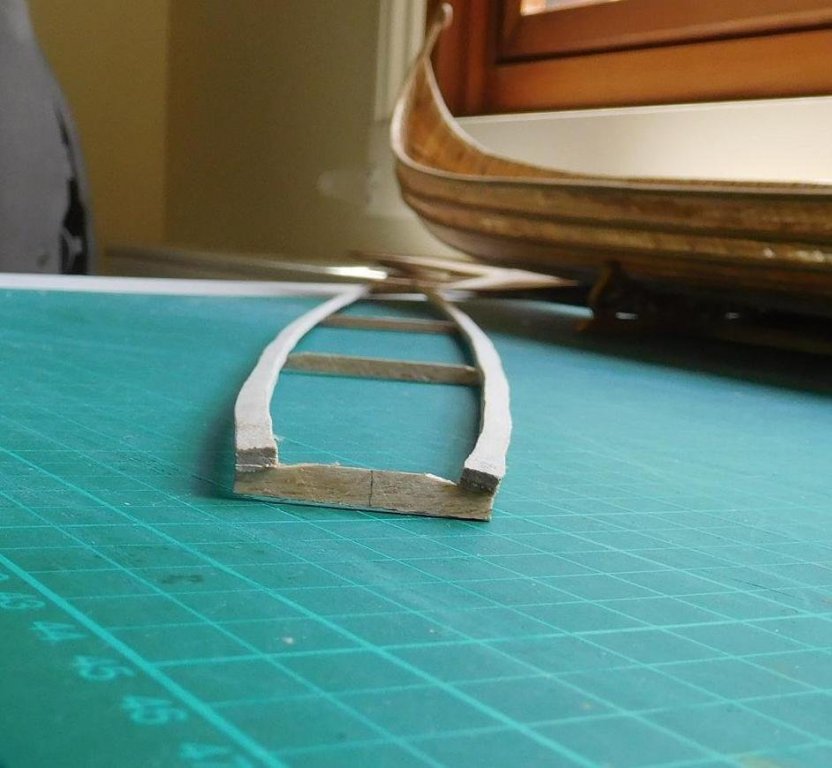
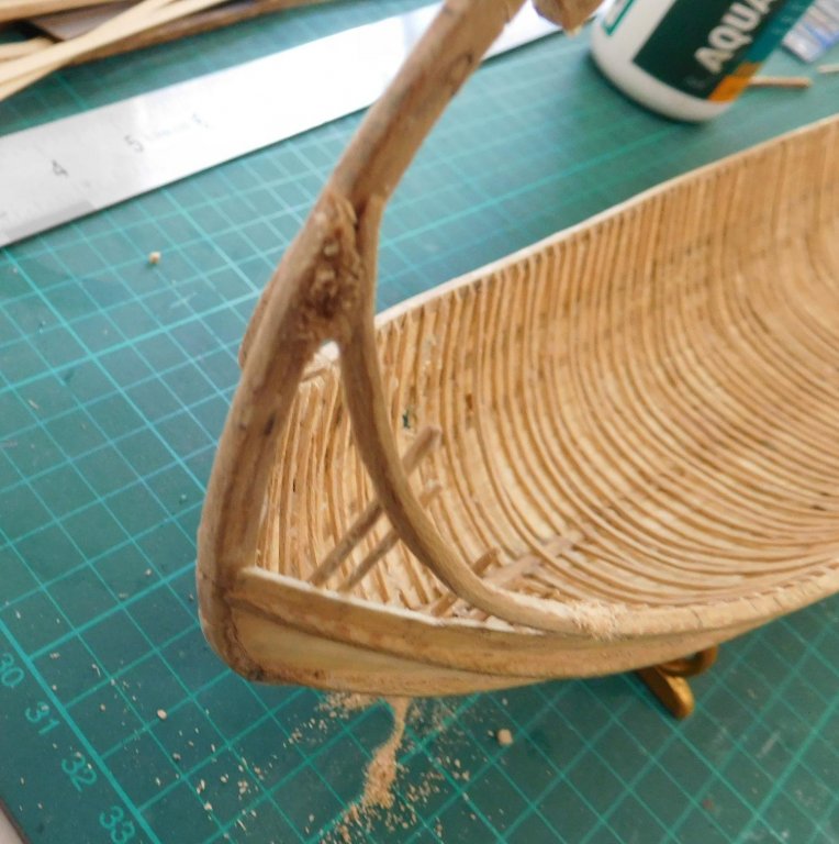
And here it is bent to shape.
 I didn’t have clamps that reached far enough to hold it in place while the glue dried, so I acted as my own set of clamps. Only seven to go.
Steven


.jpg.349d31a9e065812de88067b0ce5c4bc8.jpg)


Venetian Carrack or Cocha by woodrat - FINISHED - 1/64
in - Subjects built Up to and including 1500 AD
Posted
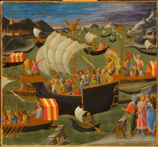
Dick, I got it from Pinterest, a source that is both valuable and occasionally extremely frustrating for its lack of attributions. It is ascribed to Gregorio Dati, a Florentine merchant and diarist who lived from 1363 to 1436, (wikipedia entry at https://en.wikipedia.org/wiki/Gregorio_Dati ) and is apparently held in the New York Public Library, Spencer Collection MS MA 110. It is only vaguely dated (c.1400, which seems to be definitely too early). It could be an illustration from one of his books, but seems definitely later than when they were written.
Regarding the strange "stunsails", the have me flummoxed. A very pretty picture, but I have no idea what connection it has with reality.
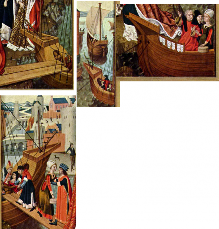
There are several navi tonde (I think that's the plural) with only a single extra mast - the Reixach carrack has a mizzen but no foremast and the picture with the blue tent (above) and the picture immediately above it both show carracks with a foremast but no mizzen.
I think you're right to do the mizzen at the very least. As far as I can recall, you built the upper works on the assumption that they'd have to make room for a mizzen mast.
It's a beautiful build, I'm really looking forward to seeing her complete.
Steven