


Louie da fly
-
Posts
7,980 -
Joined
-
Last visited
Content Type
Profiles
Forums
Gallery
Events
Posts posted by Louie da fly
-
-
Hi Vivian,
This is a great era to be working with - not enough people make models from this time period.
As far as I can see, the 15th-16th century Mediterranean cocca is the same ship as the nave tonda (round ship) and further west would be called a carrack (same ship, different names).
I see you're already aware of Woodrat's brilliantly researched Venetian nave tonda, and I'd highly recommend you study his build log carefully if you want to get your 15th century details right. I certainly found several of my own assumptions about carracks had to change in the light of Woodrat's research - for example the shape of the bow - the carrack had much finer lines and a sharper bow than I'd thought.
It's evident your model is based on the contemporary one below.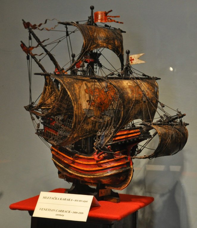
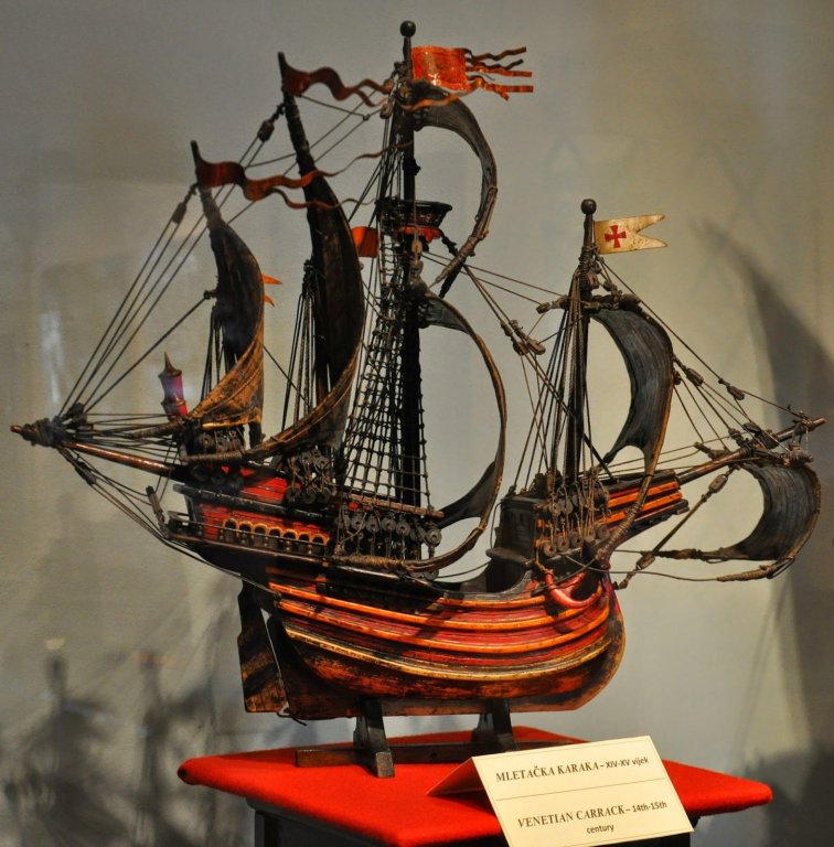
I haven't seen this one before, and it's very interesting. It's oversimplified and some of the details are incorrect; I expect it's a votive model - these were often donated to a church by a mariner in gratitude for a safe voyage. But it is very evidently a 16th century ship - the four masts and the rig make this certain. Changing it to a 15th century ship might involve a lot of work - perhaps more than it's worth.
The Mataró ship is genuinely 15th century, and maybe you should just build this kit as it is rather than try to change it, and then once it's complete start on the Mataró ship .
Steven
-
I’ve finally started the planking on my dromon. It’s been a long time coming.
I’m very grateful to Woodrat who heard I had no proper bench saw of my own so he cut sheets of pine half a millimetre thick and sent them right across Australia for me to make my planks from (the guy across the road had cut some for me, but though I appreciate the gesture they were 50% thicker at one end than the other and really weren’t usable).
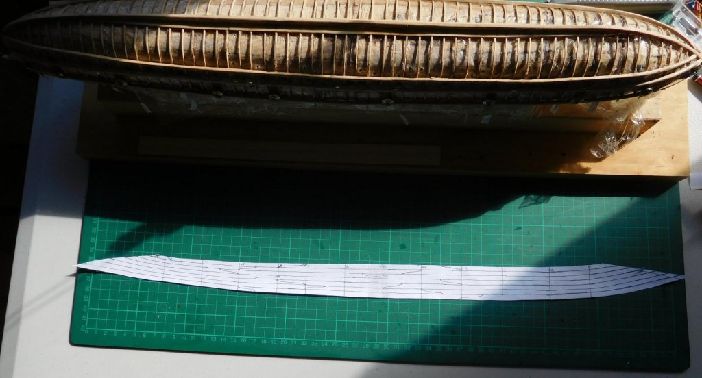
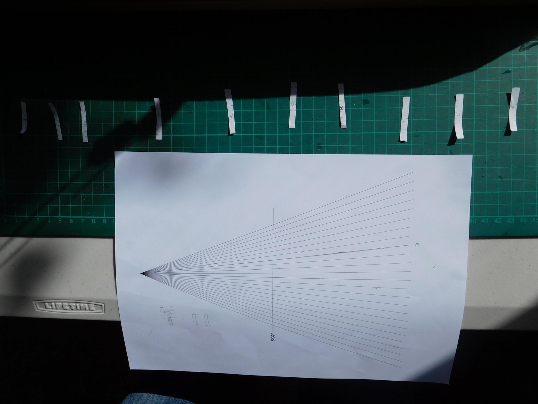
I did a lot of reading on planking techniques, because I really wasn’t confident I knew what I was doing. I decided to use the planking guide I found on the MSW site but I had trouble working out how to go, and after a lot of thought I worked up a template that suited my style of working. It may not suit everybody or every ship, but it seems to work for me. Following the method I got from MSW, I made up strips of paper to determine the width of each plank where it crossed a frame, dividing the distance between the keel and the first wale by the number of strakes (in this case 8, including the garboard strake).

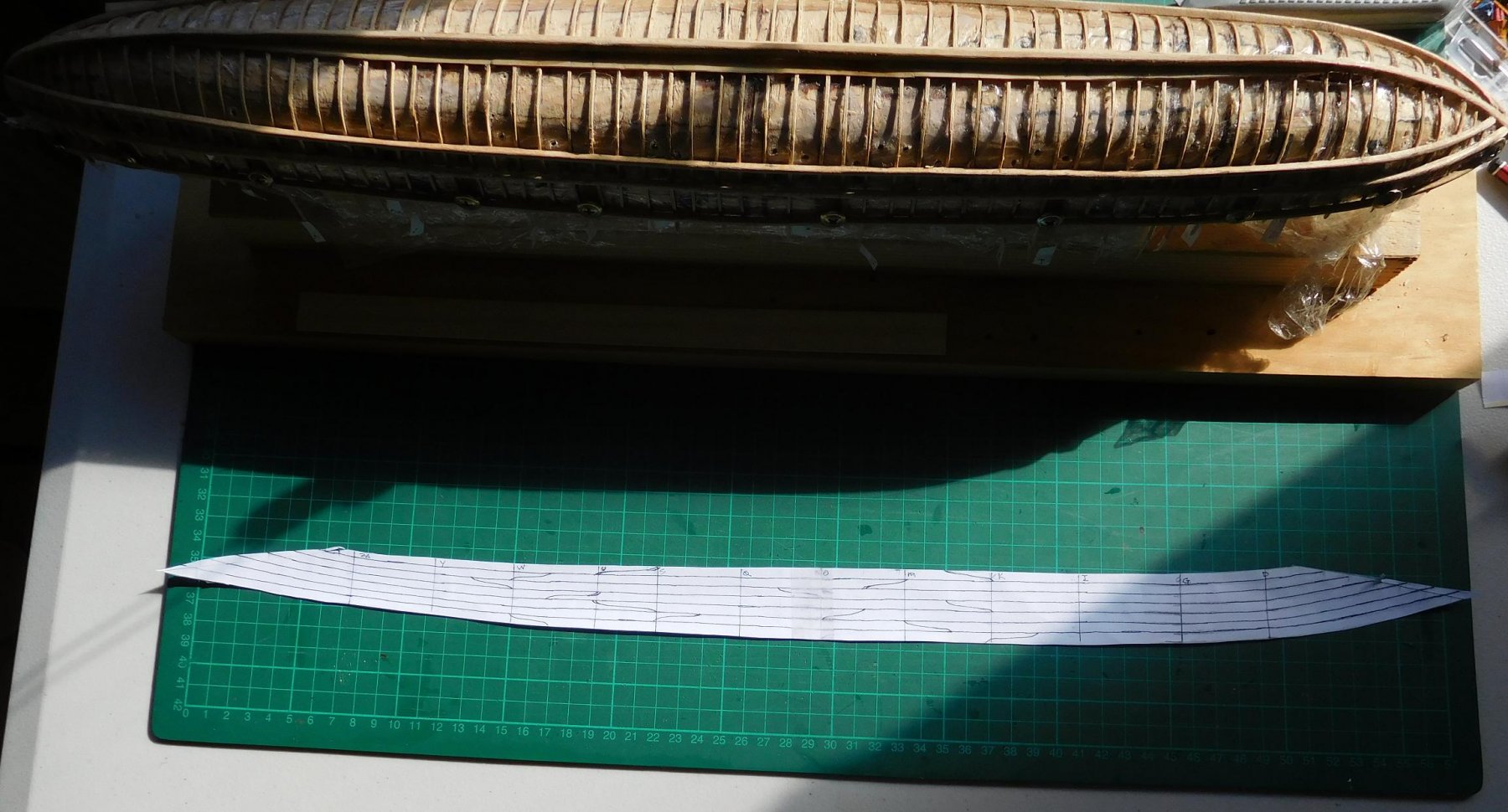
But then I went off on my own – I made up a template that covered the whole area between the keel and the wale from end to end of the ship and using the strips I marked the strake widths where they crossed the frames, and then joined the marks to draw the strakes on the template (along with placing the scarph joints).
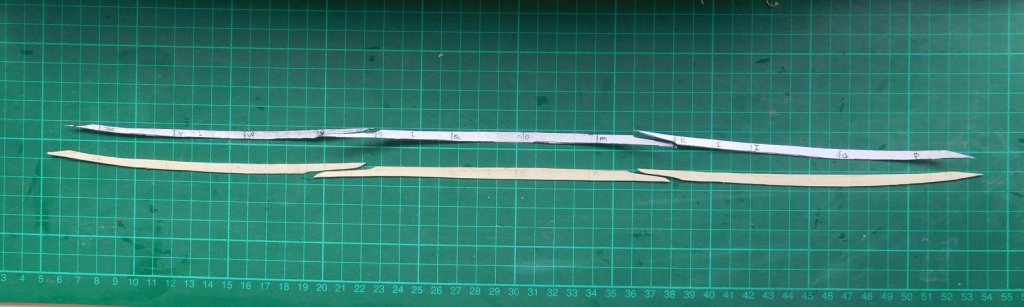
There are three planks in each run, and they are joined end to end with a long S-shaped scarph joint based on those of the Byzantine galeae found in the silted up Harbour of Theodosius in Istanbul (the Yenikapi ships). This kind of joint is needed because the frames are so thin it would be impossible to butt-join planks at a frame. So the joint is spread over several frames, with fixings at each frame. Surprisingly, on the Yenikapi ships these joints aren’t spaced as far apart on adjacent planks as we’d normally expect. But that is probably compensated for by the strength of the scarph.
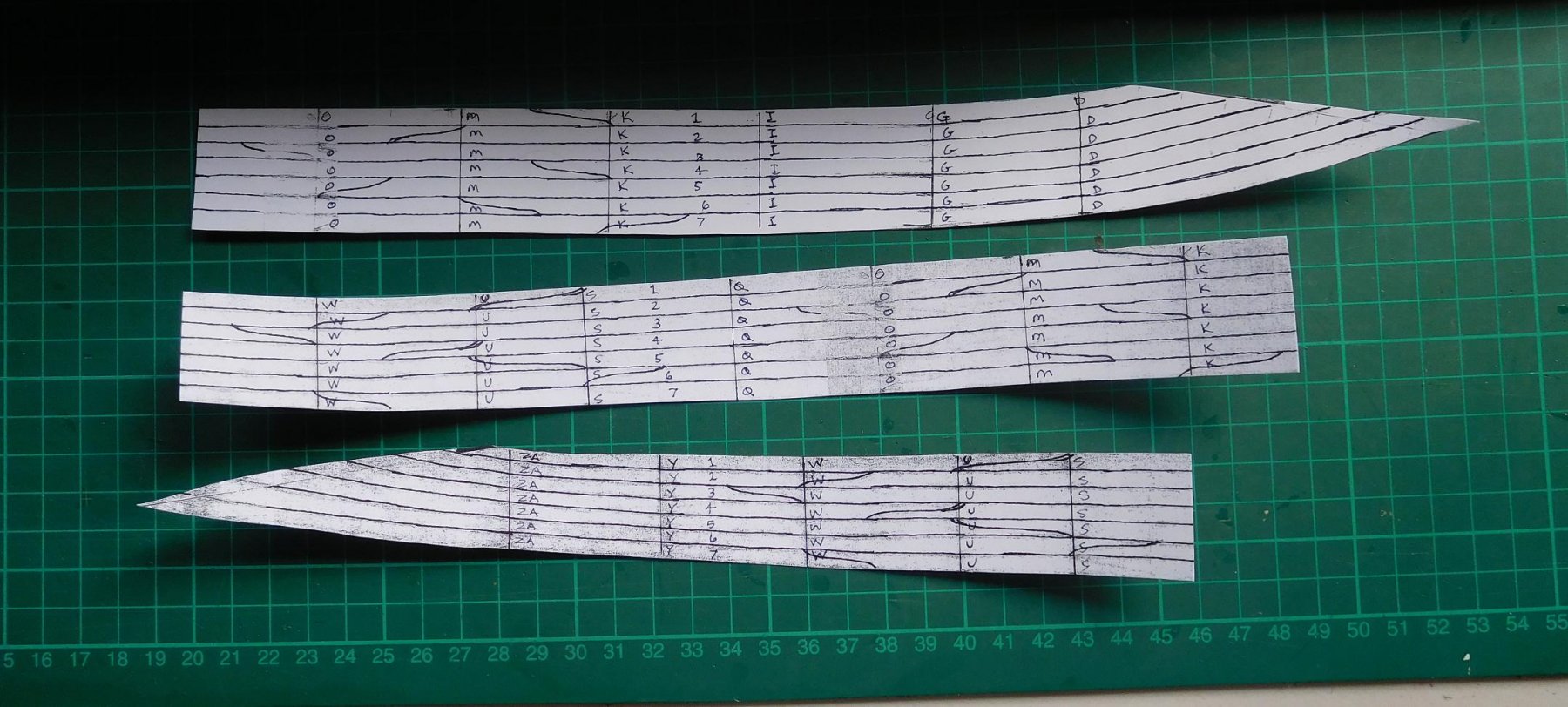
Then I photocopied the template and glued it onto card. I cut it into three sections – to make the three planks in each run.

After that I could cut out individual plank templates from the card and transfer them to the wood of the strakes.
Then it was a matter of trimming the edge of the strake so it fitted exactly against the keel (for the garboard strake) or the edge of the next strake. Very fiddly.
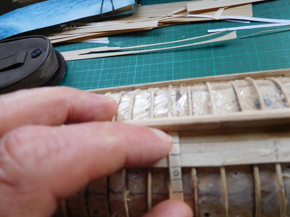
After that I used my strips of paper to check that I had the width of the strake right. It was always too wide – maybe the pencil wasn’t sharp enough - so then I marked the right width at each frame and drew a freehand curve to join the marks and trimmed the strake to width.
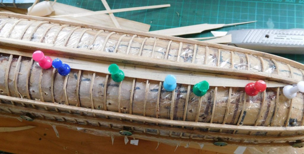
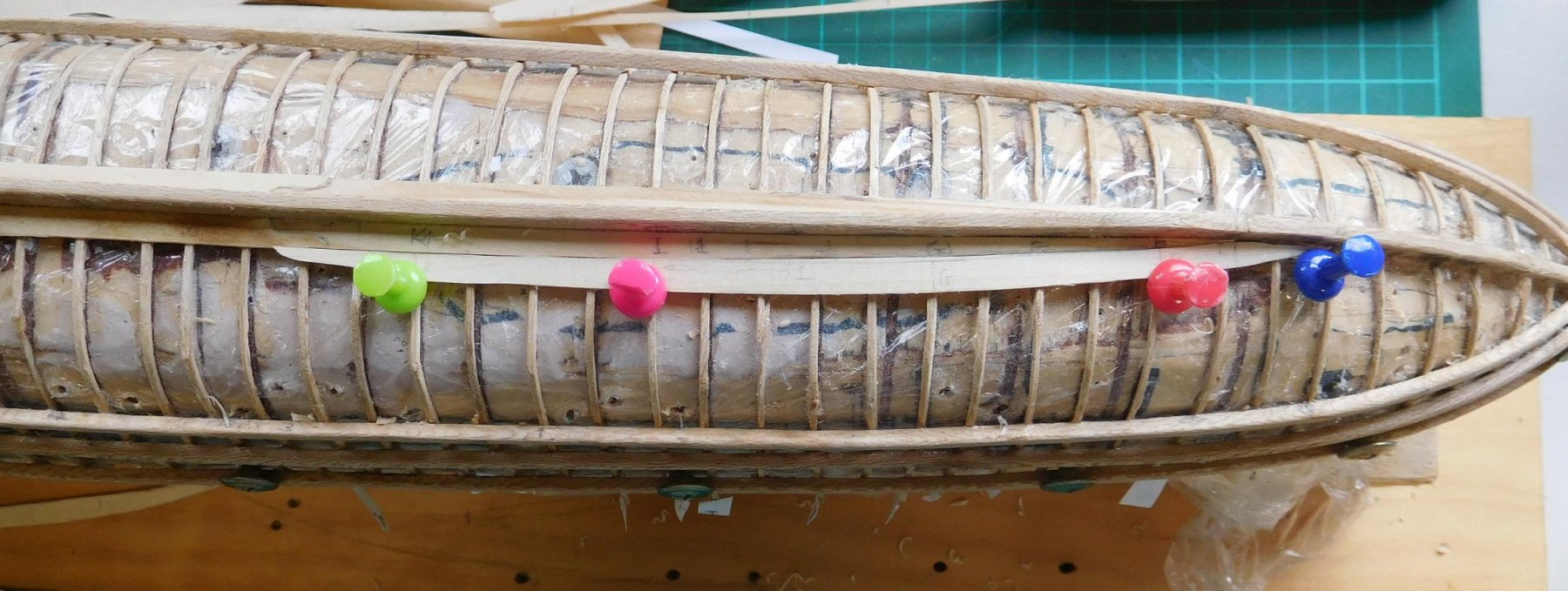
Checking the strake width with the guide.

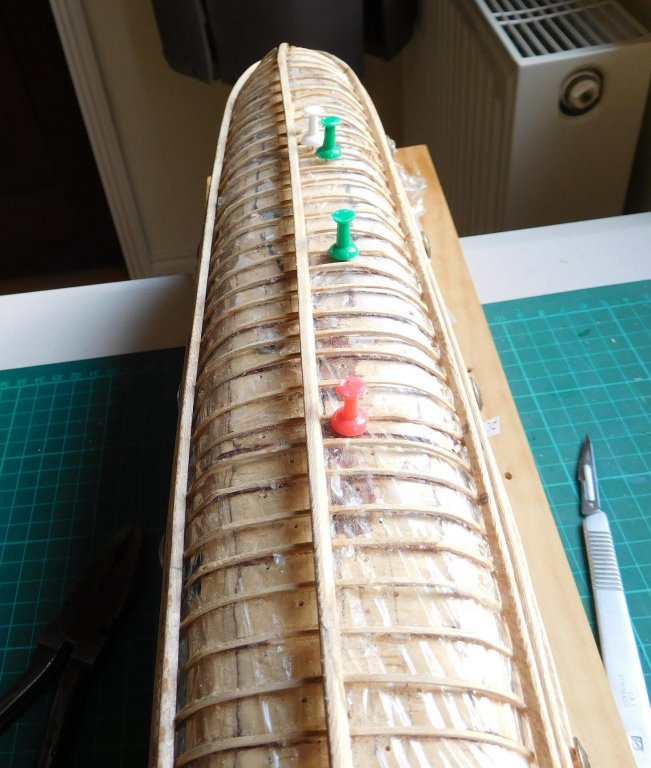
I used push pins to hold the planks in place. This meant I had to drill a whole lot of 1mm diameter holes in the plug (with a hand-held drill, so always running the risk of breaking the drill) to hold the pins. I put glue on each frame (just the width of the strake) and glued along the inner edge of the strake and along the scarph joint.
I started with the garboard strake – not the starboard garboard; it was the larboard garboard. So far I have both garboard strakes and three planks on one side . It’s very fiddly and demanding work and takes much more time and effort than I’d expected. But it’s very rewarding.
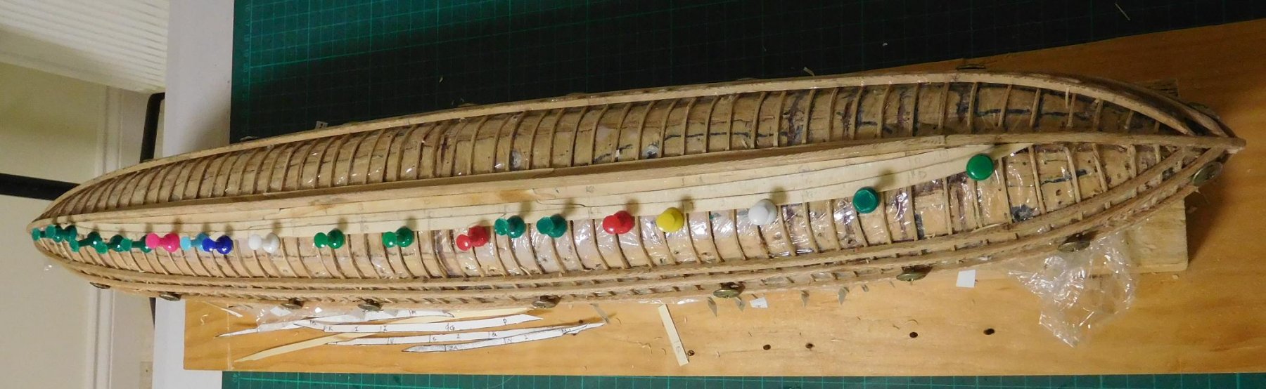
Here's the first plank dry fitted.

And glued down.
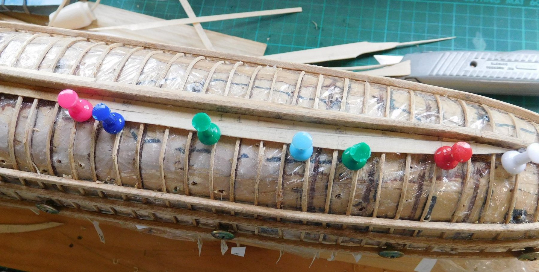
Here's the garboard and the first run of planks (the pale blue rectangle is the packet of pine sheets Woodrat sent me).
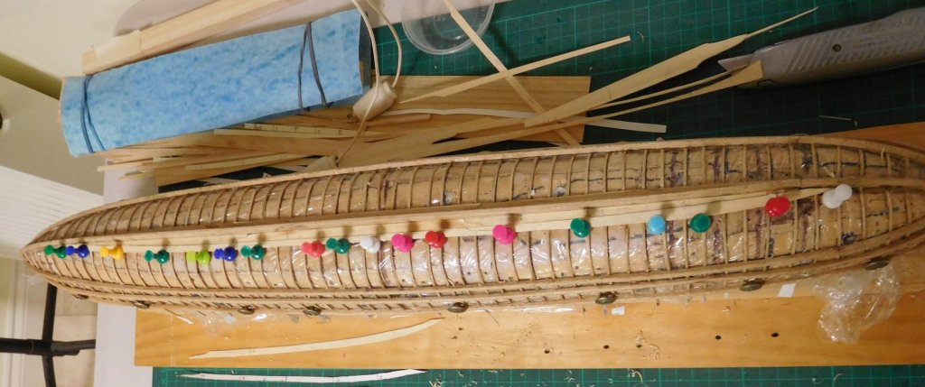
And the second run of planks fitted and glued in place.

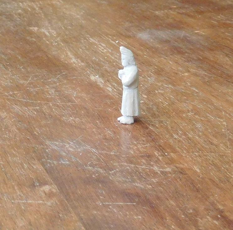
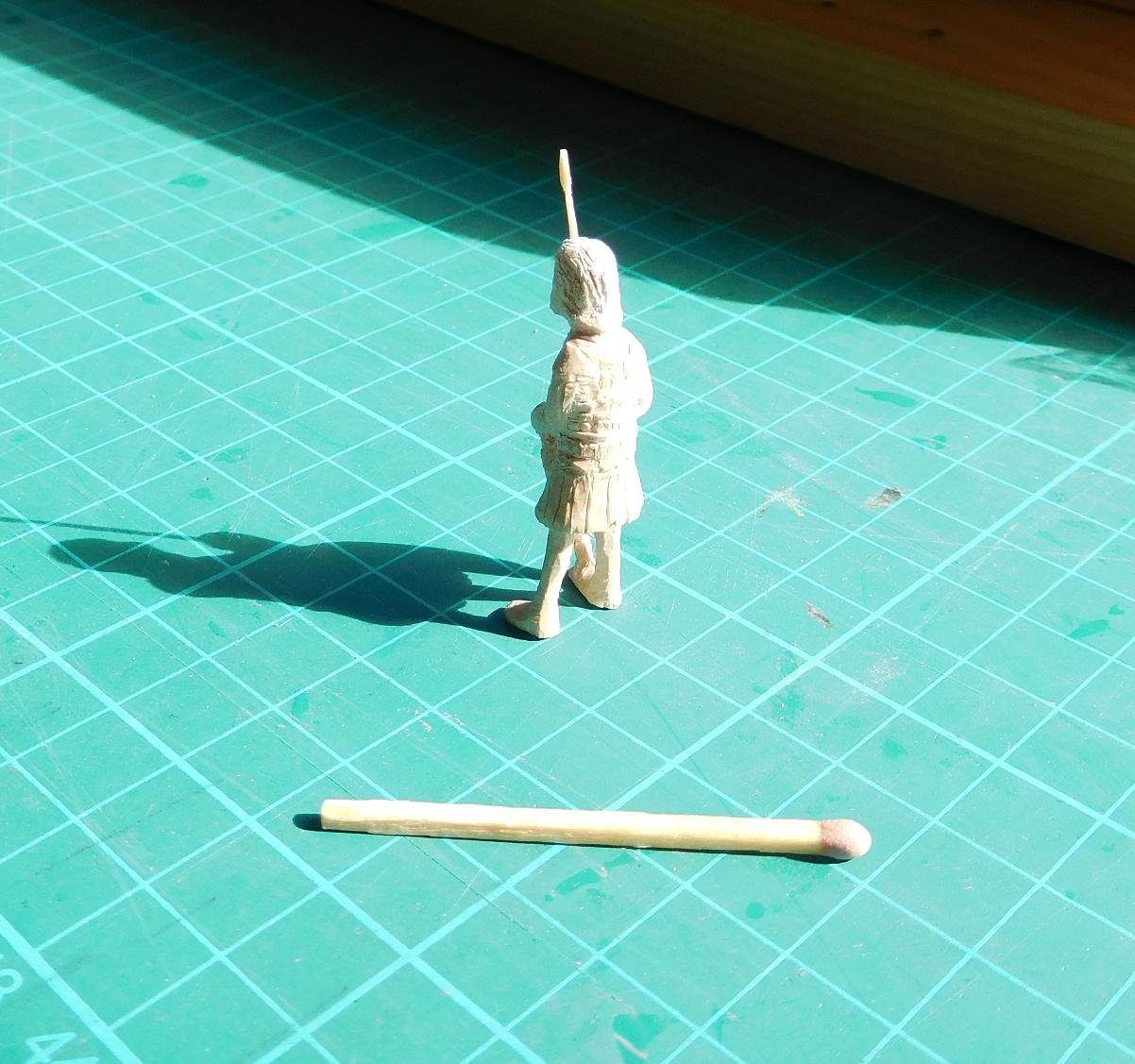
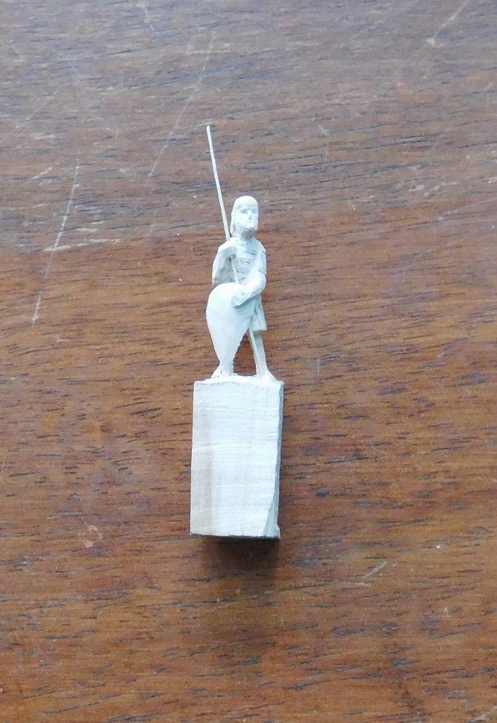
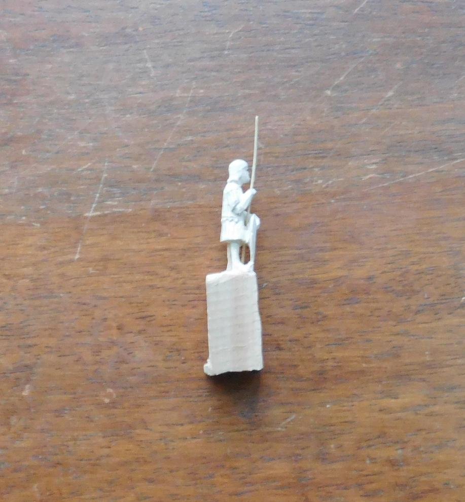
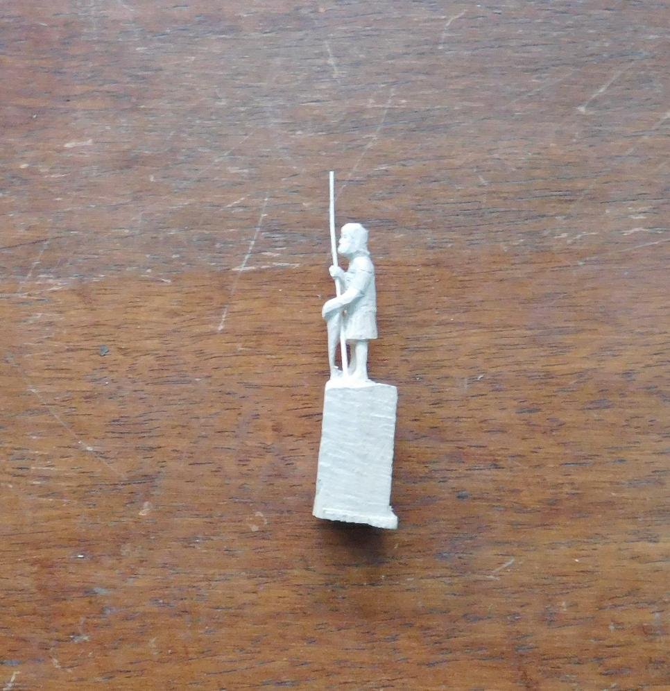
I’ve also been working on the Imperial guardsman to accompany the Emperor on board the ship. I’ve done the detail work on his armour and his hair. He just needs a bit of sanding and painting and he’s complete. Matchstick included for scale.
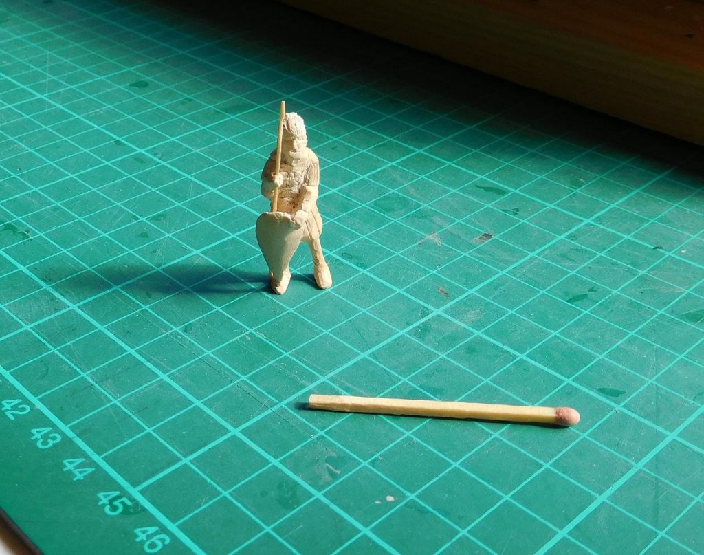
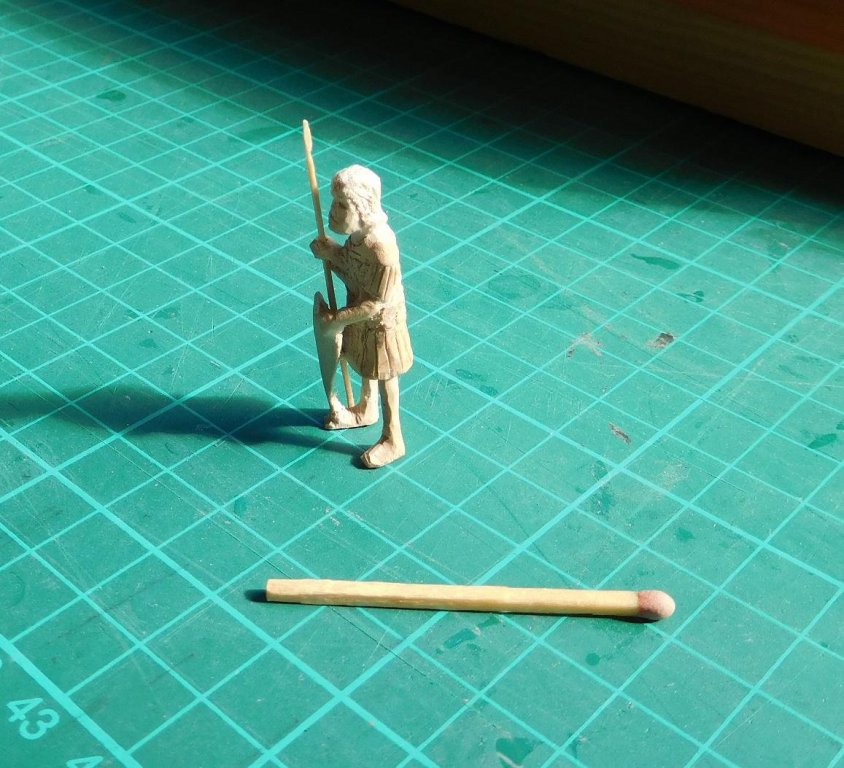

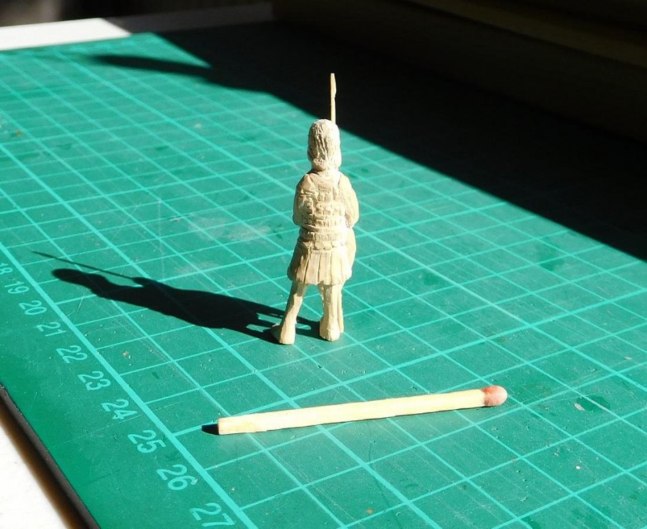
I made him taller than everybody else – he’s going to be one of the Emperor’s Varangian (Russian Viking) guards. The Vikings of Russia were described by the Arab traveller and chronicler Ibn Fadlan as “Blonde-haired, ruddy and taller than date palms”.
I think my carving’s getting better. Unfortunately, this makes me a little dissatisfied with my earlier efforts and want to re-do them. But that way lies madness . . .
The detail of these figures is sufficient for the scale they’re in, and anyway they’re just accessories for atmosphere - they’re not supposed to distract the attention from the ship itself. Currently I’m at the limit of the detail I can put in just wearing my normal glasses. If I wanted to improve it I’d have to invest in a super-duper magnifying glass, which I’m not prepared to do.
Steven
- mtaylor, rybakov, Vivian Galad and 7 others
-
 10
10
-
Thanks for the compliment, Druxey. I think they're improving, too.
Banyan, thanks very much. It's greatly appreciated. I'm pretty gobsmacked at the generous nature of the people on this forum.
I did take Dick up on his very kind offer and he's going to be cutting the pine for my planks, for which I'm very grateful.
I've been wanting to get together with other ship modellers in Victoria - just don't get the chance. I'd love to compare notes with others of like mind (very hard to talk ship modelling with normal people - they don't understand the obsession).
PS: Love your HMCSS Victoria.
Steven
-
Paul, great idea to start at the beginning of Hornblower's career. I have almost the whole set - I've read them all except Flying Colours, and I've lost my "Hotspur" (must get another copy!).
But when you get to "The Happy Return" you may find a few minor discrepancies between it and the other books - it was the first Hornblower book written, and Forester seems to have developed Hornblower's personality somewhat differently in later books about his earlier career (an author's privilege, I suppose). It doesn't spoil the story, though.
-
At a quiet point on the build and (all right I admit it) I've got rather fired up by the carving bug.
So, the Emperor needs bodyguards, right? Well, here's the first one (not quite complete, but well on the way). He's wearing full Byzantine lamellar armour except for his helmet. He's loosely of based on one of the illuminations from the Skylitzes Chronicle, but I've put him in armour instead of court costume.
This took about 5 hours, I suppose (I wasn't counting).
I'm afraid the picture quality isn't the best.
I didn't take photos of the first stages. He's quite a way along when the photos start . . .

Next stage:

Finished for the day . . .


He's still got to have his armour carved into the torso, sleeves and skirt - you can see the pencil lines - and the whole thing needs to be smoothed off, cut off the piece of wood and painted. The spear is just a sliver of wood I had hanging around. I'll have to make him a proper one.
I think I'm getting better. I'm pretty pleased with the face, for example. And I'm certainly taking on more adventurous and difficult projects. Lots of "negative space" (openings), especially around the shield.
Steven
- Eddie, flying_dutchman2, mtaylor and 1 other
-
4
-
I agree with CaptArmstrong. It is very reminiscent of the late Roman/early Byzantine armour, which itself harked back to ancient Greece. The 'muscled' breastplate and the pteruges on the upper sleeves etc, and even the buskins could have come straight from the Barberini ivory (below).
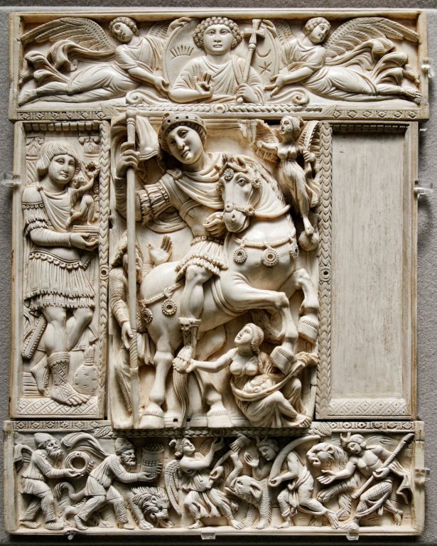
And rather than an accurate portrayal, this would be an 18th century person's idea of what the ancient Greeks wore.
- mtaylor, druxey, CaptArmstrong and 1 other
-
4
-
A small clarification of the seal, in case anybody was wondering why the dexter (Latin for right-hand) figure is on the left and the sinister (Latin for left-hand) figure is on the right, instead of the other way around. Seal descriptions come from the mediaeval art of heraldry - the study, rules and blazoning (describing in heraldic technical terms) of a person's coat of arms.
The blazon relates first and foremost to the design on the shield, and describes the figures and designs from the viewpoint of the person holding the shield, not the viewer. So from the viewer's point of view, sinister is on the right and dexter is on the left . . . It's confusing, but that's the way it's been ever since heraldry began, and there's nothing we can do about it but learn to live with it. (A bit like pushing the tiller to port when you want to go to starboard . . .).
As it's a seal rather than a coat of arms, I doubt that colours would be specified. I've looked at google images, and they show the background (field in heraldic terminology) as either white (argent) or blue (azure).
With this as a basis, and choosing a white background, the blazon would go something like this -
"Argent, a windmill's sails in saltire [i.e. as a diagonal cross] proper [in its natural colours].
In chief and base [top and bottom] a beaver statant [standing] or possibly couchant [lying down, but with head raised - there's no heraldic term for crouching, which is what these beavers appear to be doing] proper .
In dexter and sinister a barrel proper [note that if the barrels were lying on their sides they would be called tuns.]
For a crest, an eagle displayed [standing facing the viewer with its wings spread and head turned to the right - if it was facing the other way I think it would be described as regardant (looking backwards), or perhaps just "facing sinister"].
For supporters, dexter a sailor holding a plummet in his dexter hand, sinister, a native American (or whatever the correct heraldic term may be) holding a bow in his sinister hand, both upon a laurel branch in fess [horizontal] above the date 1625.
Motto "sigillum civitatis novi eboraci"
The whole within a laurel wreath proper."
I've probably committed all kinds of heraldic blunders in this blazon, but it's not too far from how it should be.
As you can see, it's a very technical and precise subject. The blazon is supposed to be phrased in such a way that anybody should be able to produce a picture of the coat of arms (or achievement) just from reading it.
Perhaps not too germane to the discussion, but it's a subject I find fascinating.
Steven
- mtaylor, coxswain, uss frolick and 2 others
-
5
-
Messis, to answer your question about shellac,
"Shellac is a resin secreted by the female lac bug, on trees in the forests of India and Thailand. It is processed and sold as dry flakes and dissolved in ethanol to make liquid shellac, which is used as a brush-on colorant, food glaze and wood finish."
You probably know it by another name in your own language.
Steven
- Canute, achuck49 and thibaultron
-
3
-

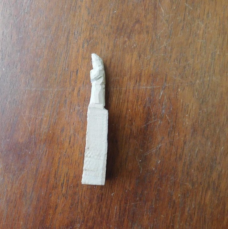
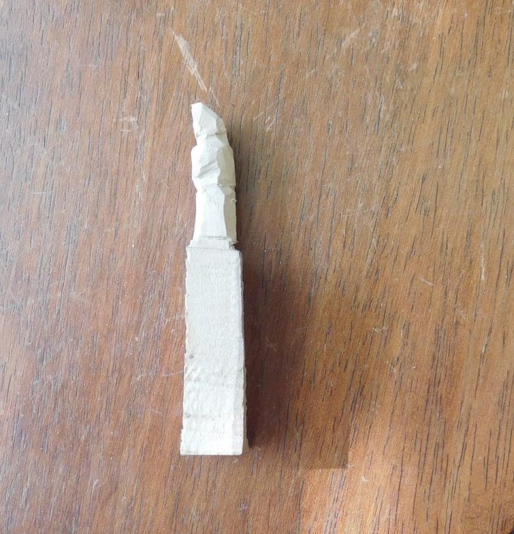
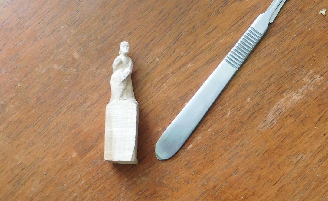
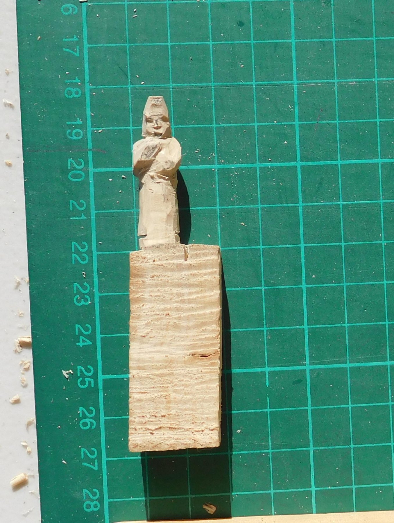
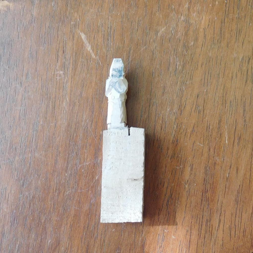
Next step in the carving process. What I call the Megatron stage - because the figure's face resembles some kind of Transformer. I've roughed out the face and given the arms more definition, as well as slightly trimming the body a little closer to the size and shape I want it to be. From this point on, I get very careful about shaving off more wood and only take off a very little at each time, have a look, compare it to how I want it to look, take a little more off and look at it again etc. It's easy to take wood off, but if you've cut off too much you can't put it back.
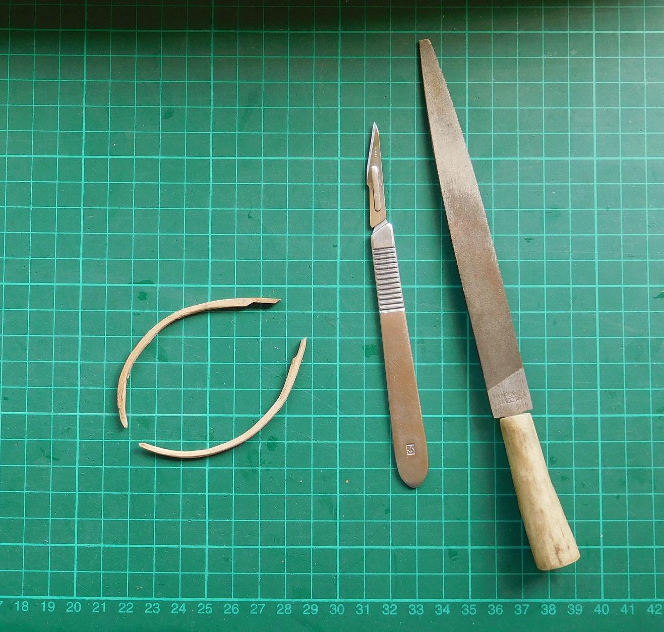
At this point I move from a Stanley knife

to a scalpel with a No. 11 blade for the finer work.
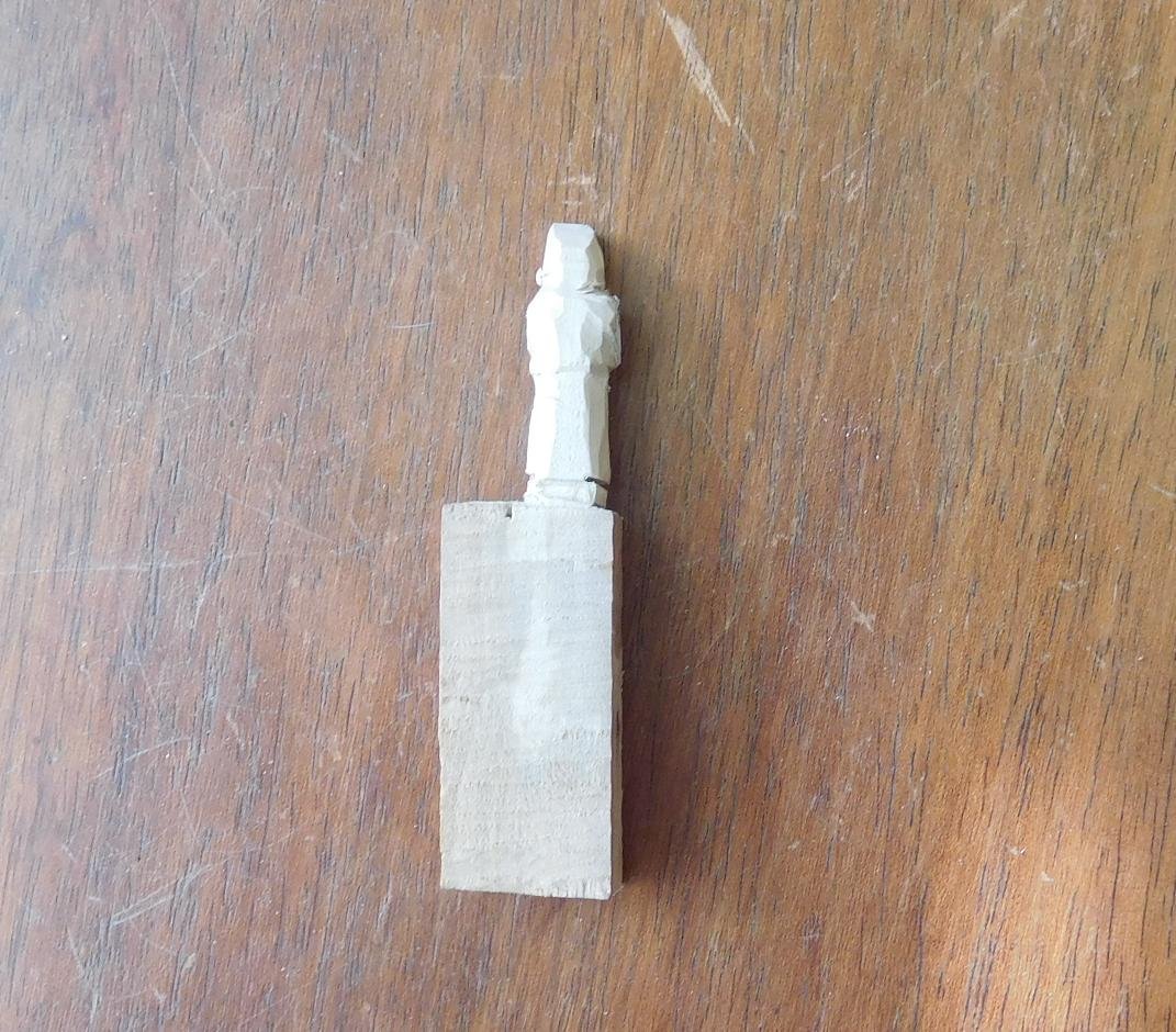
Now I put a lot of effort into getting the face right. Once that's ok I go on with the body. If I mess up the face I have to throw the figure away and start again. I might as well do it now, rather than do all the work getting the body perfect and then have to throw the figure away because I messed up the face - it's just wasted effort.
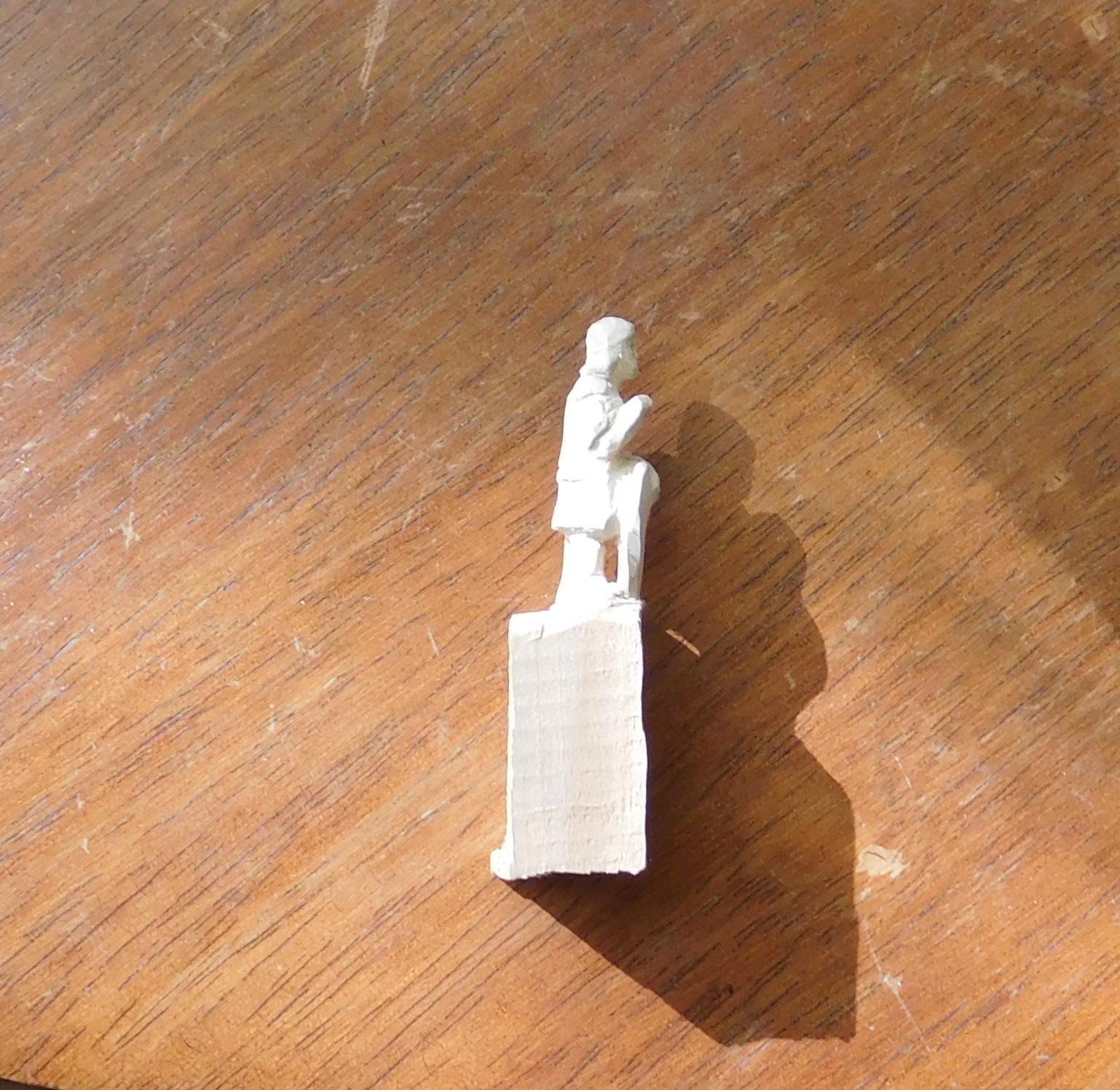
Still somewhat Megatron, but looking a bit more like a human's face.
And here he is from the side
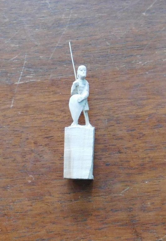
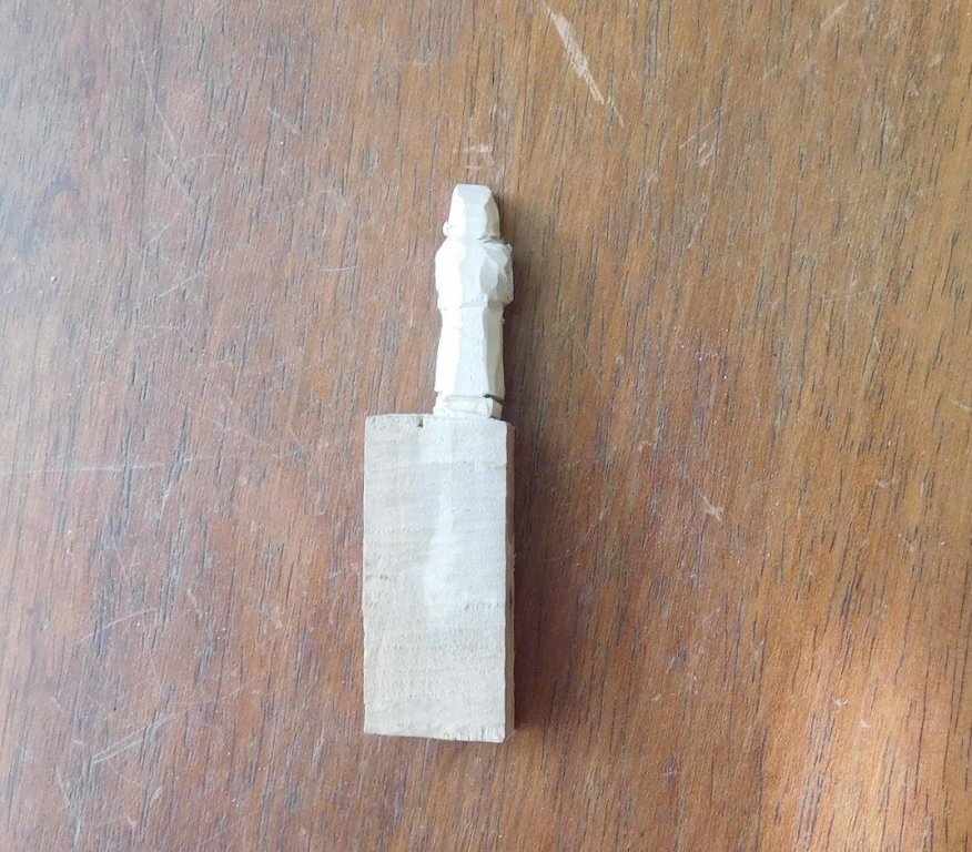
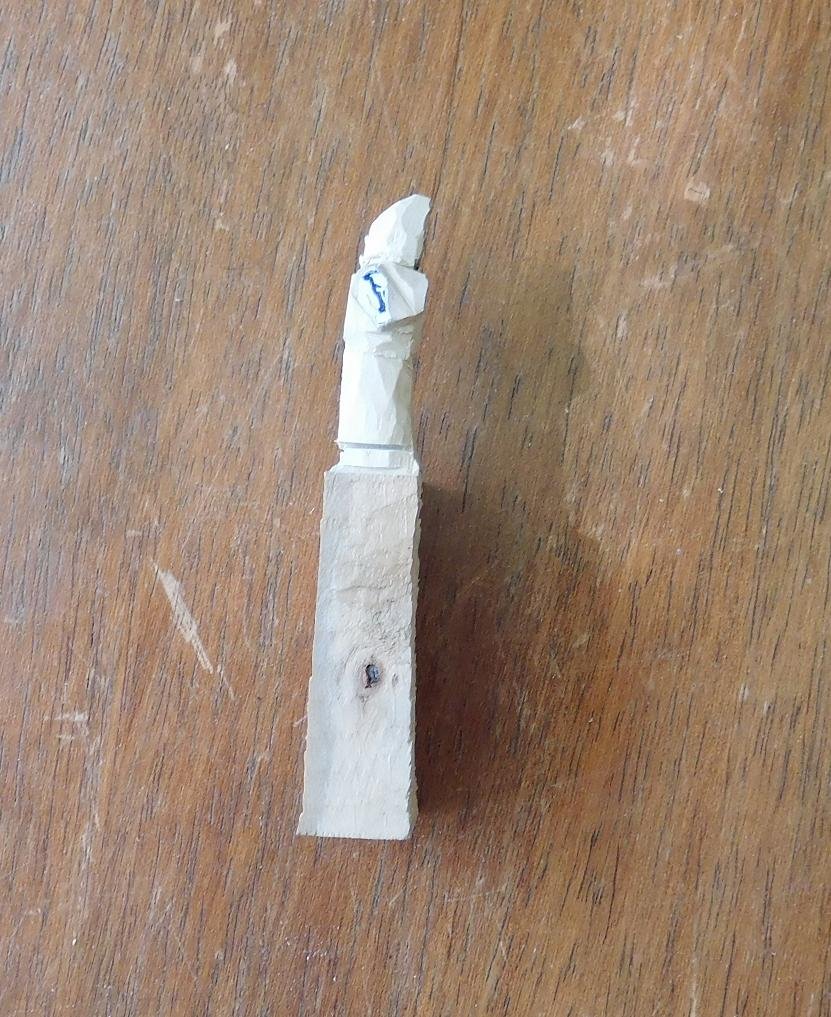
Unfortunately, the next photos in the carving sequence came out all blurry, so I've had to skip a step. Here's the figure almost complete.
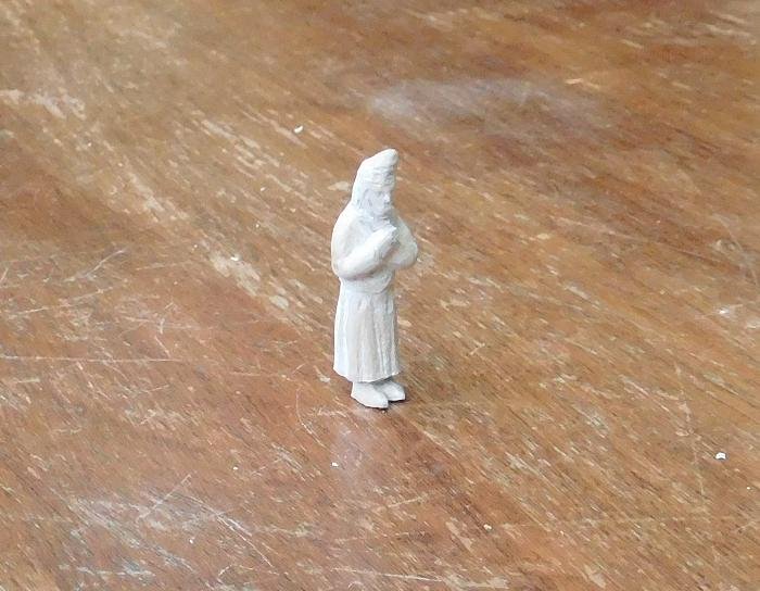
I'm afraid he looks a little like a Tolkien dwarf, but when he's painted up he should look more Greek and less dwarvish - the "dwarf's hood" is really some kind of turban, and I think a good paint job will point this up. And I have the chance to show the Byzantine splendour of the clothes.
Oh, and I only realised from looking at the photos that his pedal extremities are colossal - his feet's too big. I'll trim them down and I think this will reduce the dwarvish look as well.
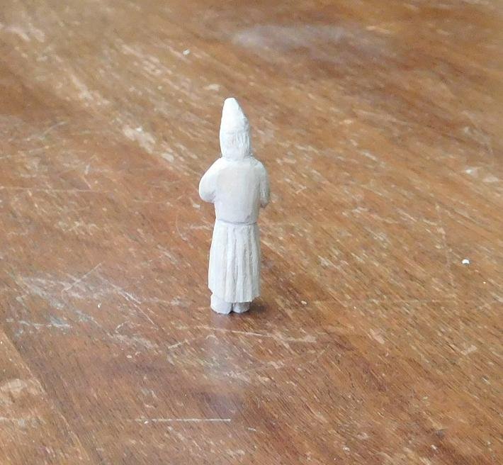
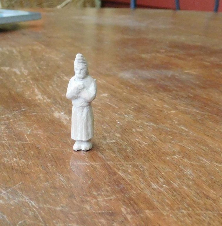
I'm pretty happy with those fingers . . .
Steven
- John Allen, Eddie, davyboy and 7 others
-
10
-
Thanks everybody for the likes.
Thanks for the idea, Druxey, and for the offer, Woodrat. Currently I'm going ok - the different thicknesses at the plank ends shouldn't be a problem - the difference is very minor. But I might take you up on it later, Dick.
To be honest, the timber is just radiata pine that I got from Bunnings. It's the nearest thing I have to the black pine that the original ships were planked with, and I'm trying to approximate as closely as possible from Australian sources the types of wood, thicknesses and weights of the original timbers, to get some idea of how heavy the hull would have been in the original by making it to scale. Once I weigh the hull of the model I'll multiply by the scale cubed (i.e 50x50x50) to get overall tare weight. It might be off by as much as 100% or even more due to the inaccuracies in the method, but it'll give me some idea of the ballpark we're working with. Not for any particular reason except personal interest and satisfaction.
Druxey, I'm very fortunate in Ballarat that we have lots of European street trees - elm, ash, oak, plane - as well as fruit trees, particularly pear and apple, growing in people's back yards or even self-sown on the side of the road. We have two plum trees in our yard and I've even got a whole lot of walnut from when the neighbour's tree died and he gave me the timber. When the council workers come around and trim the street trees, or there's a big storm (we just had one which split several elm trees in two just down the road from me), I manage to get a fair bit of timber.
Steven
- Eddie, mtaylor, CaptainSteve and 1 other
-
4
-
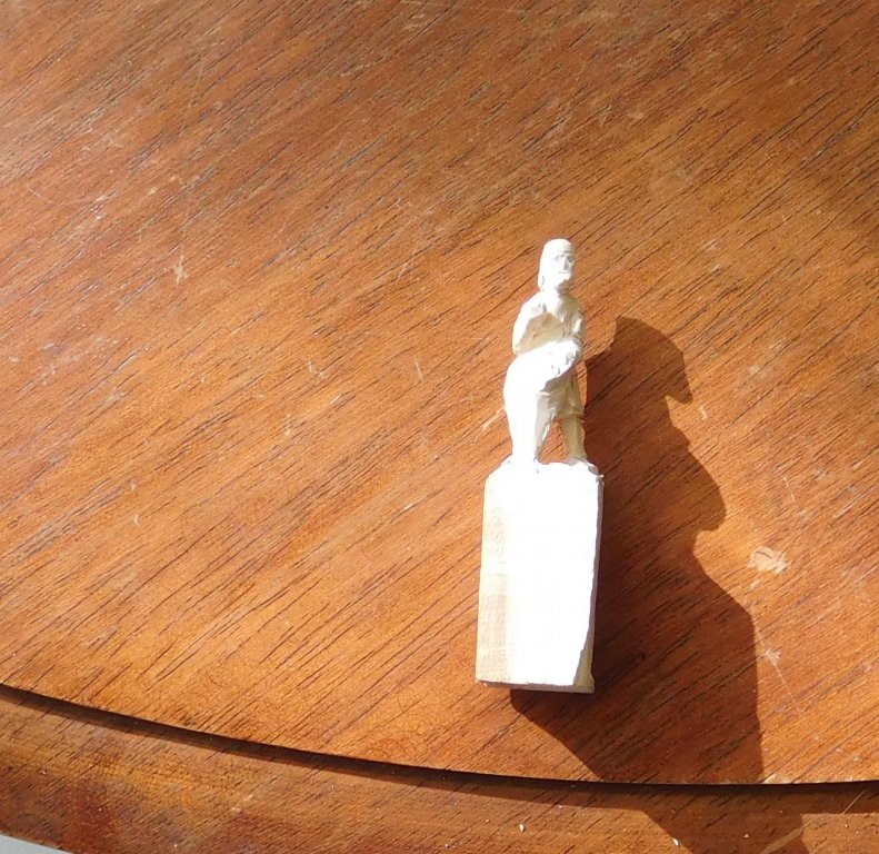
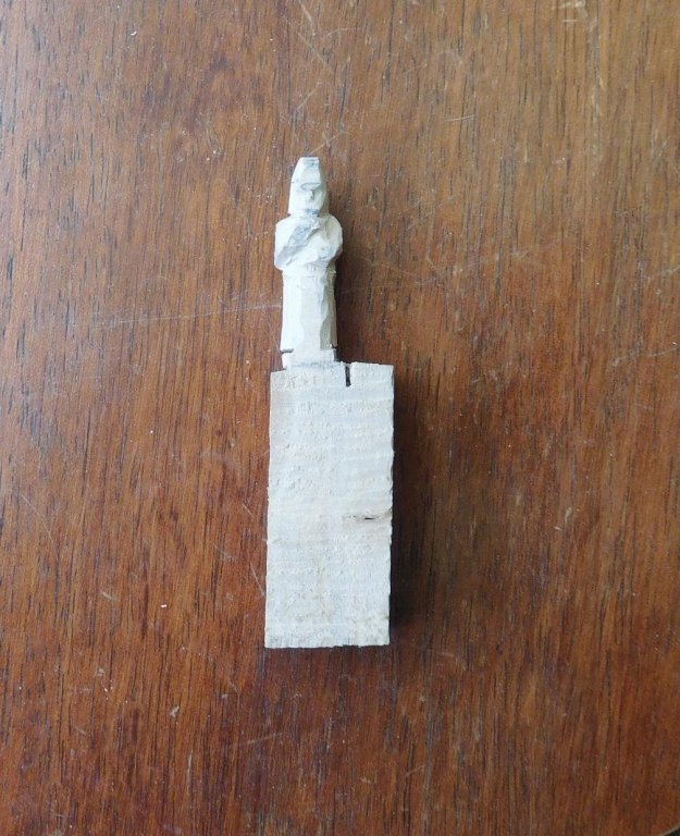
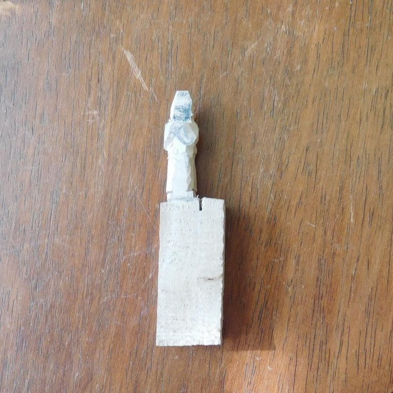
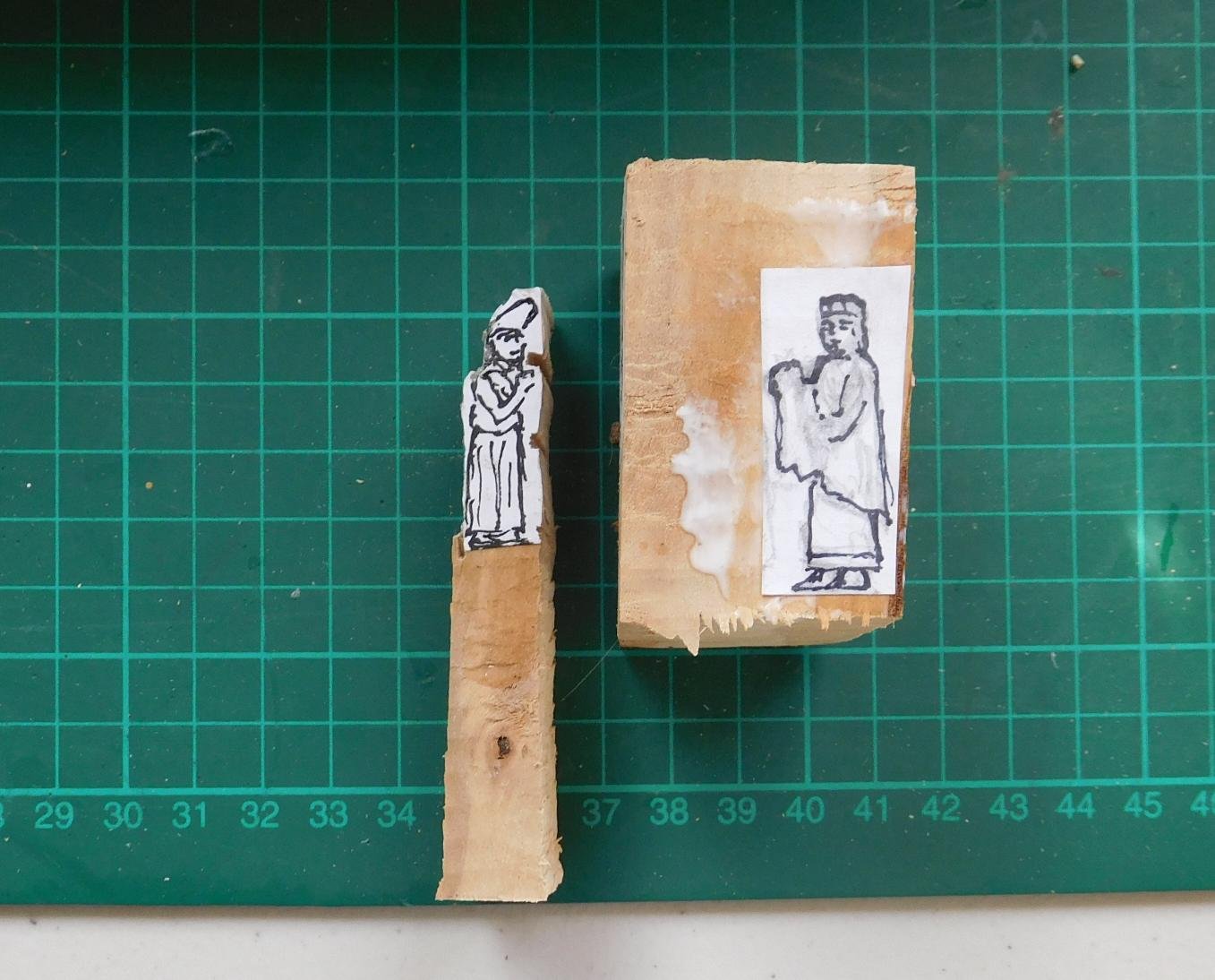
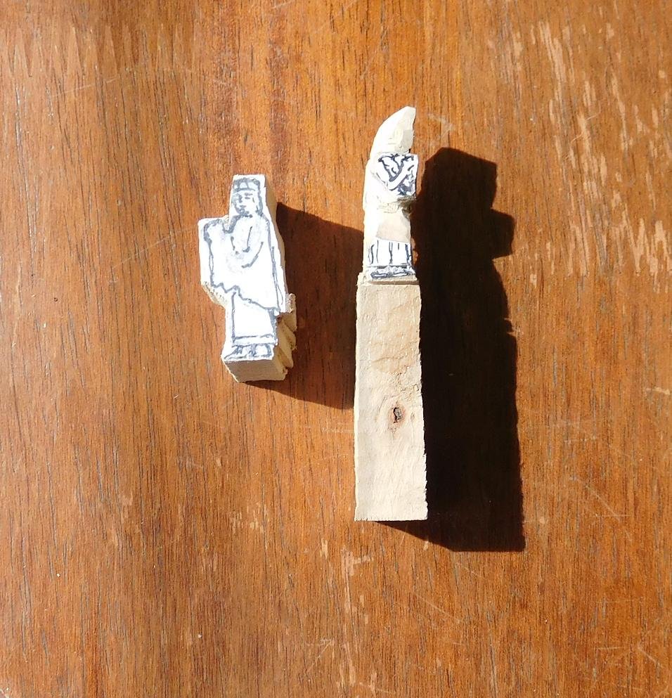
And having caught the carving bug (and with an Emperor and his courtiers to carve!) in between times while I waited for the glue to dry I've been working on extra people for the ship. Here is Emperor Alexios and one of his courtiers. I've cut out the courtier's outline with a coping saw, but the Emperor is still just a piece of paper stuck to a bit of pear wood.

Now I've cut the Emperor's outline out, and made a start on carving the courtier. I've placed the Emperor badly - I would have been better putting him higher on the piece of wood so I had something to hold onto while I carved.

The philosophy of getting a rounded figure from a squared off chunk of wood is to think of it as a series of layers. Leaving the layer nearest the outside face - in this case his arm - cut away wood from all around it, leaving the arm standing proud. You have to estimate how thick the arm is - it's often more than you think -and cut away that deep behind the arm. In this case all the detail of the head is lost as you have to cut it back to let the arm stand out. I've cut away a bit below the arm, but as I haven't yet sorted out the hem of his gown I've left it alone.
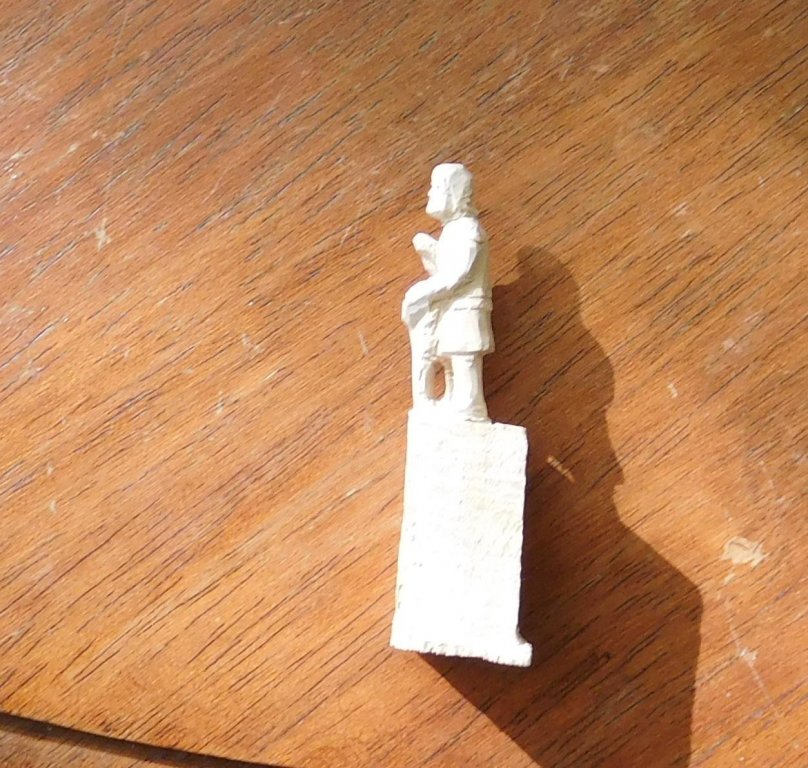
Now I've trimmed down further to begin to give the body some shape. Still thinking in terms of layers, the shoulders are the next nearest thing to the surface of the wood, so I've cut away everything around them. I've also trimmed off somewhat so the hem of the gown is in about the right place. Next I'll have to put a couple of saw-cuts across the figure to give the hem of the gown some definition and cut back to the layer of the front of his feet.
I've roughly re-drawn his face and arms to give me some orientation for further carving. I'm still trying to work out what to do with his strange hat - it leans forward over his head like a smurf's hat and I need to get it right; but all in good time. I've left myself enough leeway to come back to it and shape it more carefully later.
Here he is from the left side . .
And from the back . . .
and from the right.

More progress pictures in my next post.
Steven
- Eddie, mtaylor, kees de mol and 3 others
-
6
-
I take my hat off to you and anybody who can do all this electronic and servo motor stuff (including RC). It's something I've never had any skill at, but I never cease to be impressed by the achievements of those who do.
When I first saw your project it looked terribly familiar. I've driven across the Clyde River bridge at Bateman's Bay, which could be the Wardell bridge's twin.
Steven
-
Thanks everybody for the likes.
Druxey, if I'd had the accident the next day with the gunwale tails in place, I'm confident there'd have been no damage at all. But up till then the tail was just an accident waiting to happen. And I'd been SO careful with it up till then. Just goes to show (but I'm not sure what . . .)
Now I'm reading up on planking, using the MSW tutorials and McCarthy's book Building Plank on Frame Ship Models. The only time I've previously done any planking was with the Great Harry when I was about 17 (more years ago than I care to think about) and though that didn't turn out too badly, I'd like to do it right this time. Preferably no stealers, no drop planks, just elegant, beautiful strakes.
I'll be using pine, cut to 0.5 mm thick on the table saw belonging to the guy across the road. Unfortunately it's not a very exact saw, so about half the slivers it cut were the wrong thickness and can't be used, and all of them are a little thicker at one end than the other. I figure I can overcome this by just ignoring the problem till the strakes all in place, then sanding them all to the same thickness.
This isn't really a ship; it's a giant rowing boat 90 feet long. It's built as lightly as a rowing boat, and the frames are so thin on the full sized ship that it was impractical to join planks end to end with a butt joint -there's not enough "meat" in the frame to hold two butt jointed plank ends. So they used a very beautiful curved scarph joint (an "S" shape instead of a zig-zag), stretching across several frames. The situation is the same in the model and I'll be using the same joint myself. It'll take a little time and care to get it all to marry up but I believe it'll be worth it.
Steven
- mtaylor, CaptainSteve, woodrat and 1 other
-
4
-
Very true, Dick. If the Bayeux Tapestry, for example, is to be believed, the Normans had blue and green horses.
However, I find it interesting that out of the dozens of pictures of ships in the Skylitzes Chronicle, only these two are red and yellow, and both have the Emperor on board, and in one of them it is even labelled as the Imperial ship. Of course it may mean nothing, but the model has to be some colour, and these manuscript illustrations are the only evidence available. If I don't use them I have nothing to work off at all. I suppose I could paint it black as the other ships in the Skylitzes are, but the same criticism applies to doing that.
I can never know for sure if it's correct (without a time machine), but this artist has got many other details right (in such things as costume) and I'm prepared to give him the benefit of the doubt.
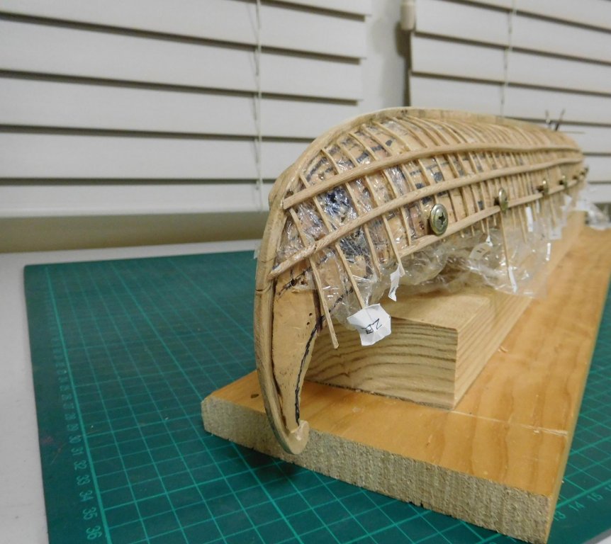
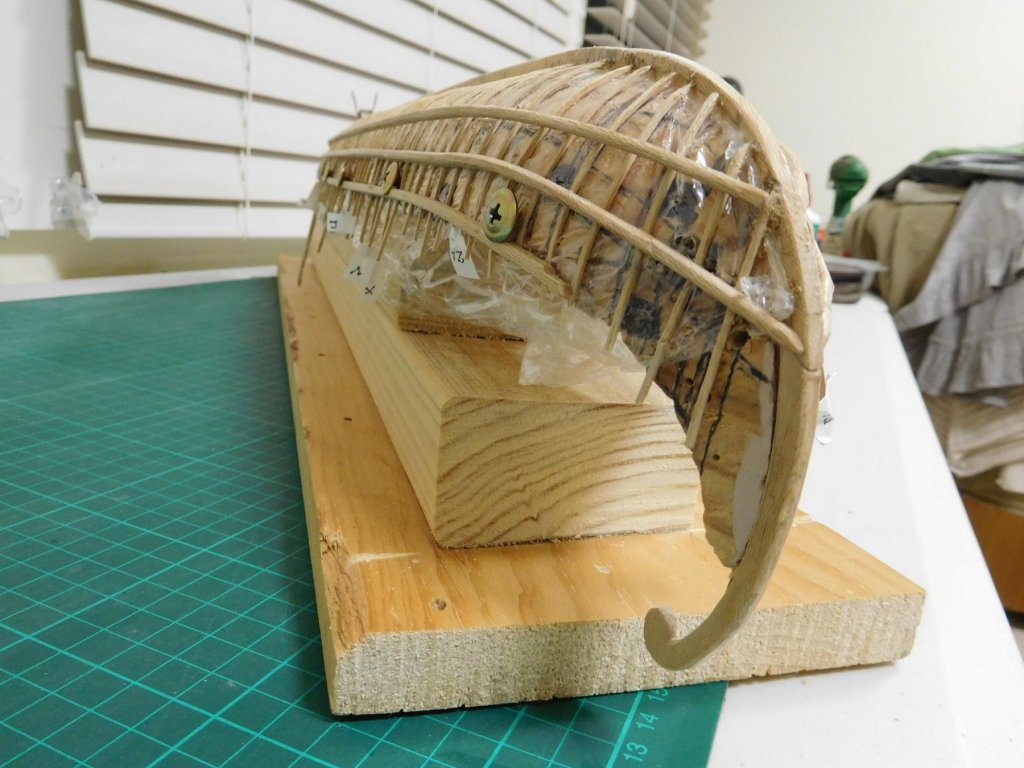
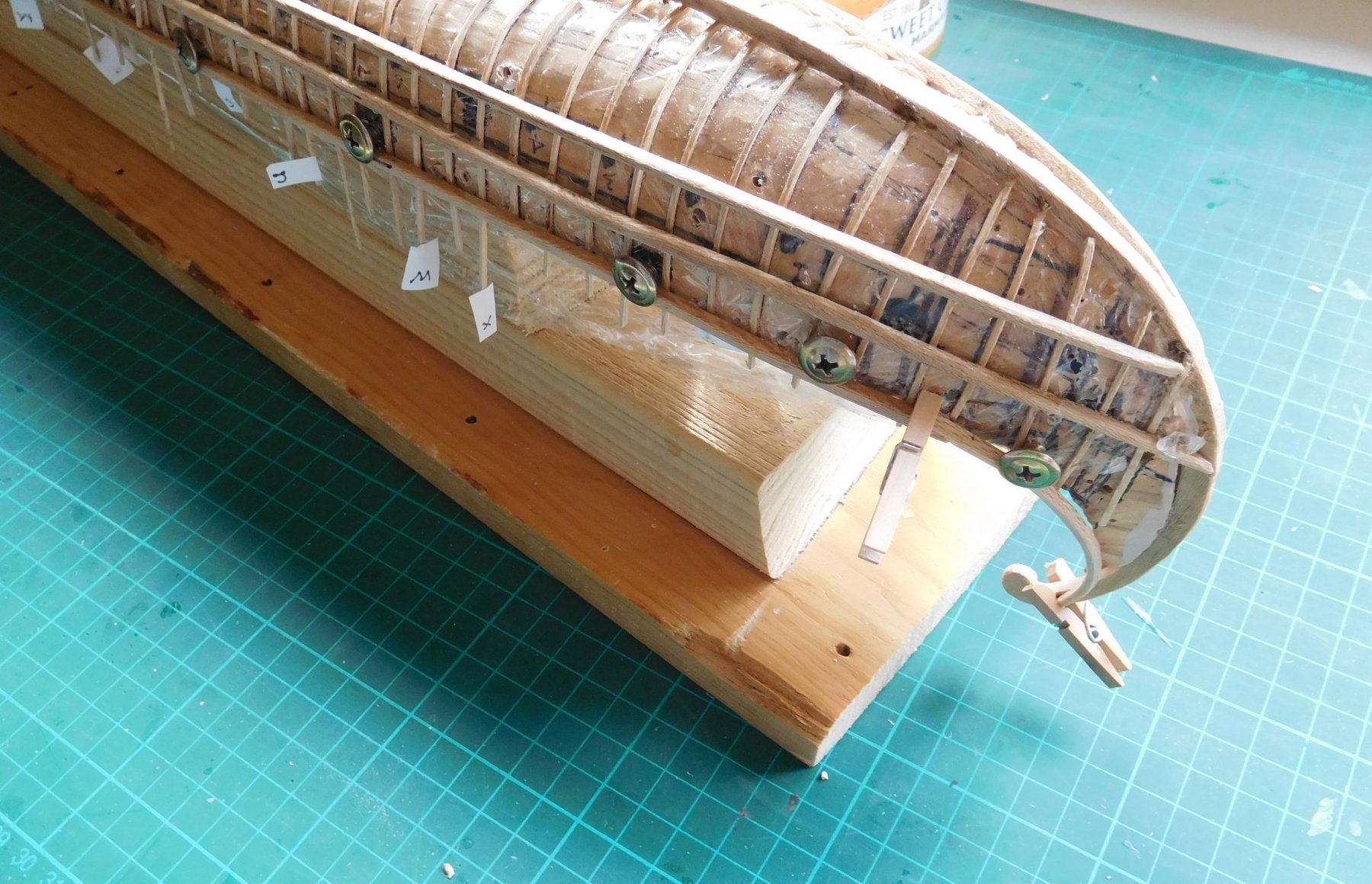
Here are some progress pics of adding the "tail" to the gunwales. The first shows the two tails - one fully shaped and smoothed off, the other still incomplete.

Here is the starboard "tail"held in place with flat headed screws and tiny pegs.
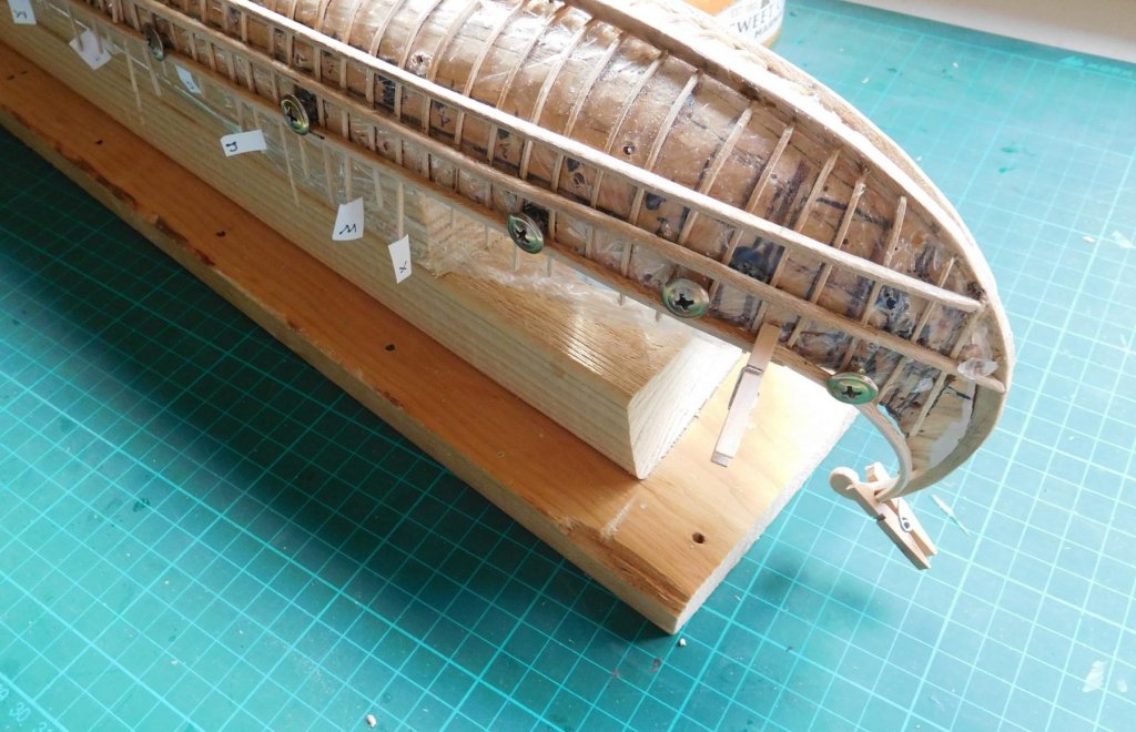
And both in place. The tiny peg was too small to span the thickness of keel and both gunwales, so I had to use a normal clothes peg.

Before I put the tails on I'd been sweeping the table to get ready to take photos and in a moment of inattention I broke the tail off the keel. Not a happy camper. I had to carefully glue it back in place (I use white glue) and hold it in my fingers till it dried enough to stay put. But it came good, and now the two gunwales brace the tail of the keel so it's not likely to snap off if a similar accident occurs. As I'd feared there is a very slight asymmetry between the two gunwale tails, but I'll be able to fix this with a little imagination, trimming and gluing.
The next step is to make the frames more uniform. Currently they don't form a smooth curve for the planking and I'm slowly remedying this. Another lesson in patience and in technique. I should have used even more push pins than I did and held each frame against the plug at more points of the curve. But I'm confident that I can make it good with patience and care.
Steven
-
I'm currently working on shaping the "tails" of the gunwales so they fit smoothly with the gunwales themselves and with the "tail" of the sternpost (I really don't have a worthwhile name for them). Photos shortly.
In the meantime I thought I'd put up these pictures of the Emperor on board a galley (perhaps a dromon, even though it only has one bank of oars - the picture may have been simplified by the artist - as far as I know there are no contemporary Byzantine pictures of double-banked galleys).
The Greek text in the first picture says the ship of the Emperor.
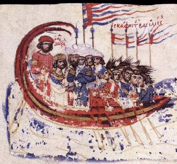
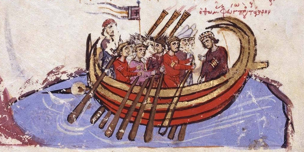
These are from the mid-12th century illustrated copy in the Biblioteca Nacional in Madrid of the chronicle of Byzantine history written by John Skylitzes. Almost all the illustrations of Byzantine galleys in the Skylitzes Chronicl, show them with black hulls, but both of these, with the Emperor and his courtiers aboard, show them in red and yellow. So perhaps this colour scheme was reserved for the Emperor's own ship. Also, though many illustrations show double-ended "banana boats", the first shows a ship with a bow suitable to take a ramming "spur" (and very similar to the intended shape of my dromon) and the second shows one (admittedly a banana boat) with what may well be a spur.
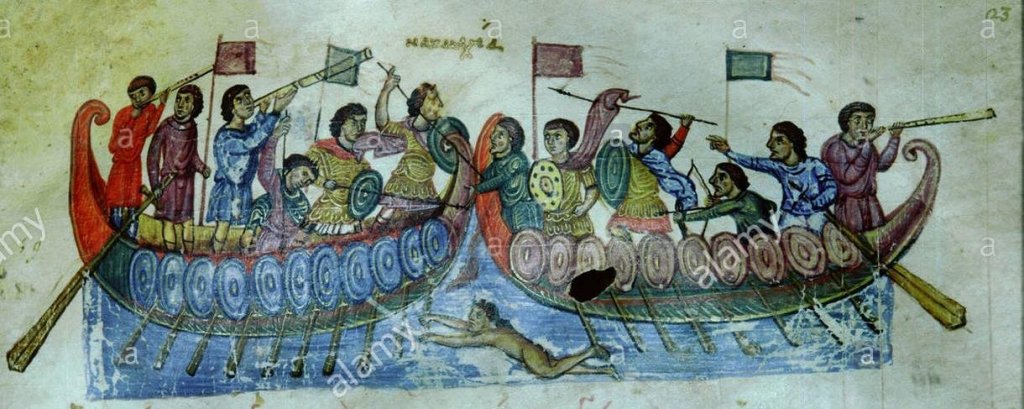
I intend to use these two as models to draw from for the colour scheme of my own dromon, and also for such details as the banners etc. There are certainly differences between these pictures and my own proposal - for example both of these galleys have two "wings" at the stern rather than a single "tail" - but from what scant information is available the double wings appear to have been a development of the 12th century; the only picture of a Byzantine galley I know of dating to the 11th century (from the Cynegetica of Pseudo-Oppian) shows a single "tail", which is what I've based my own upon. I've also taken from this 11th century illustration such details as the shape of the oars and the side rudder, though the 12th century ones are very similar anyway. And unlike any other picture I know of, this one shows a tiller on the side rudder of the ship on the left.
And these two galleys are multi-coloured - not only are the bow and stern different from the rest of the hull, but the main part of each is green with a red stripe. Even allowing for artistic licence, this may perhaps indicate that other Byzantine galleys were brightly painted.
By the way, the third figure from the left is the archetype for my carved flute player.
Steven
-
-
22 hours ago, woodrat said:
I thought the vikings were using woollen sailcloth which would explain the need for quilting.
Dick
Yes, woollen homespun. That's the current theory, at least. All they really have to go on is the pictures, and as homespun wool would probably stretch a fair bit it's thought that was the reason. However, the vikings certainly had other fabrics - linen for one, which was used for sailcloth in the great days of sail. Also a fabric made of fibre from stinging nettles was fairly common.
- mtaylor, druxey, Farbror Fartyg and 1 other
-
4
-
That's very interesting, Dick. The Vikings seem to have had a similar system of reinforcing the sails (though they used diagonal reinforce rather that horizontal and vertical), as can be seen on a lot of contemporary depictions, such as here.
- mtaylor, druxey and CaptainSteve
-
3
-
Wonderful research, Patrick. I love to see someone really taking the time to search up the evidence on how ships were built, particularly ones of this period and earlier, where information is hard to get. But the Red Bay wreck and the Gresham ship are wonderful resources that just weren't available, even a decade ago.
Steven
- mtaylor, BETAQDAVE, zoly99sask and 2 others
-
5
-
Coming along nicely, Rick. A very interesting build.
Steven
- mtaylor and vossiewulf
-
2
-
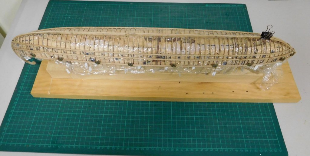
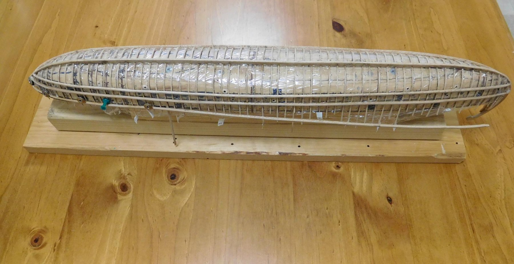
I've now made and fitted all the wales, including the gunwales, which are currently in the process of being glued in place.
I just hope the cling-wrap enables the hull to come away from the plug smoothly when the time comes, and that there aren't any pieces glued to the plug itself.
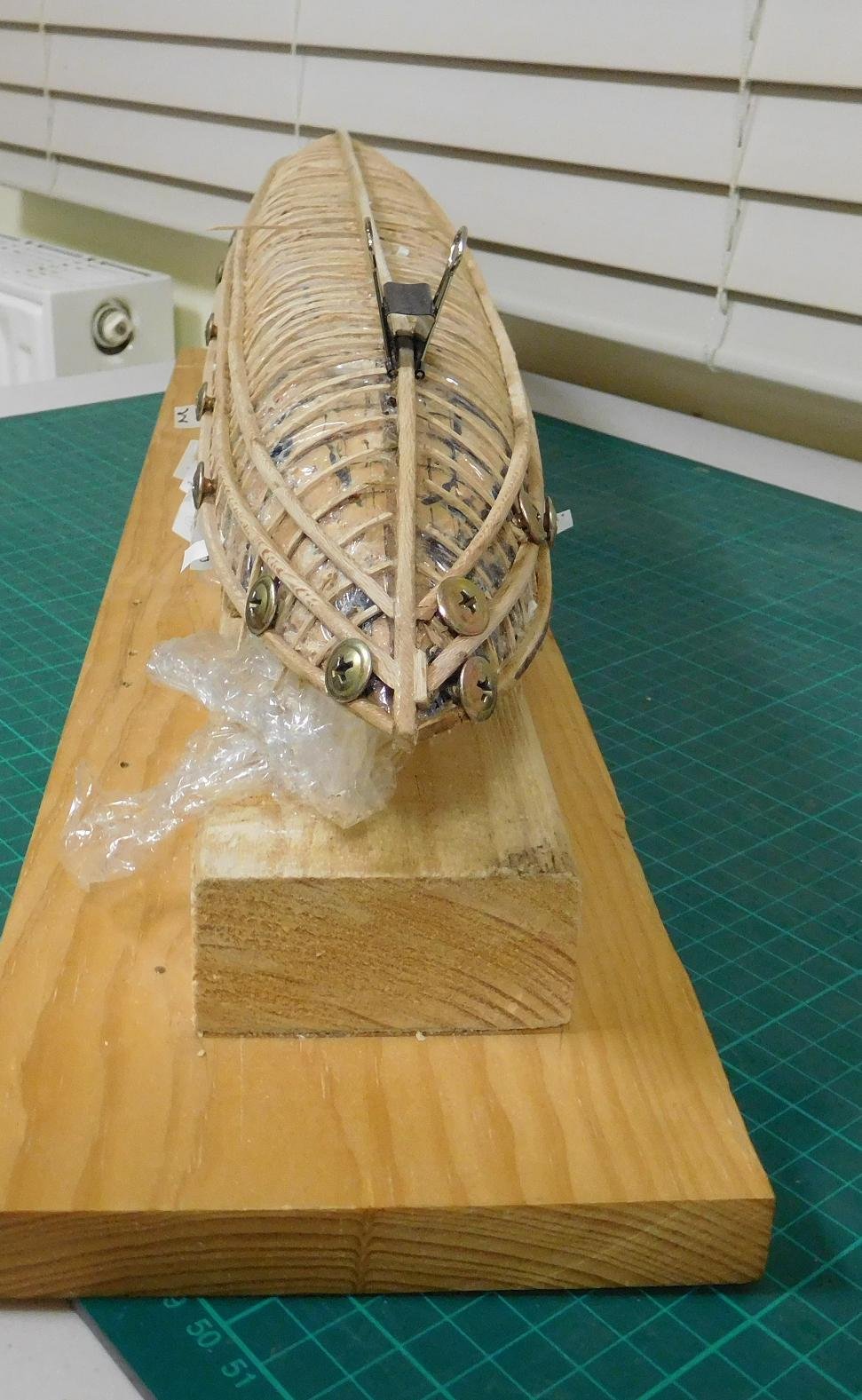
Here is the ship with all the push pins removed (except one, which was being used to hold a vagrant frame in place) and the starboard gunwale fixed at the bow.

I've replaced pushpins with large-headed screws which hold the wale in position.
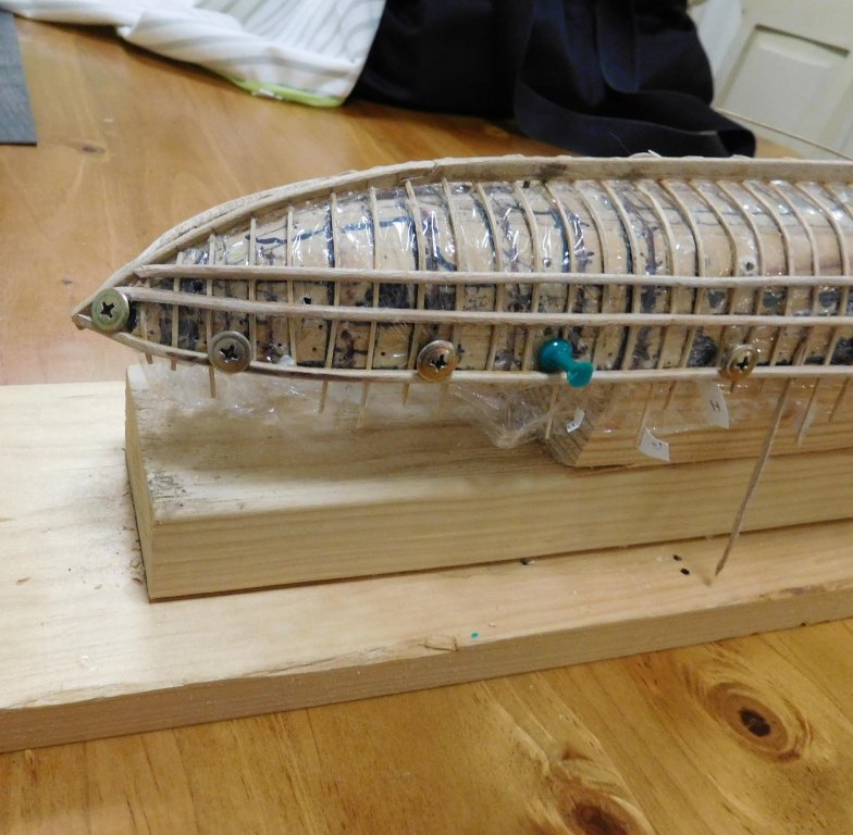
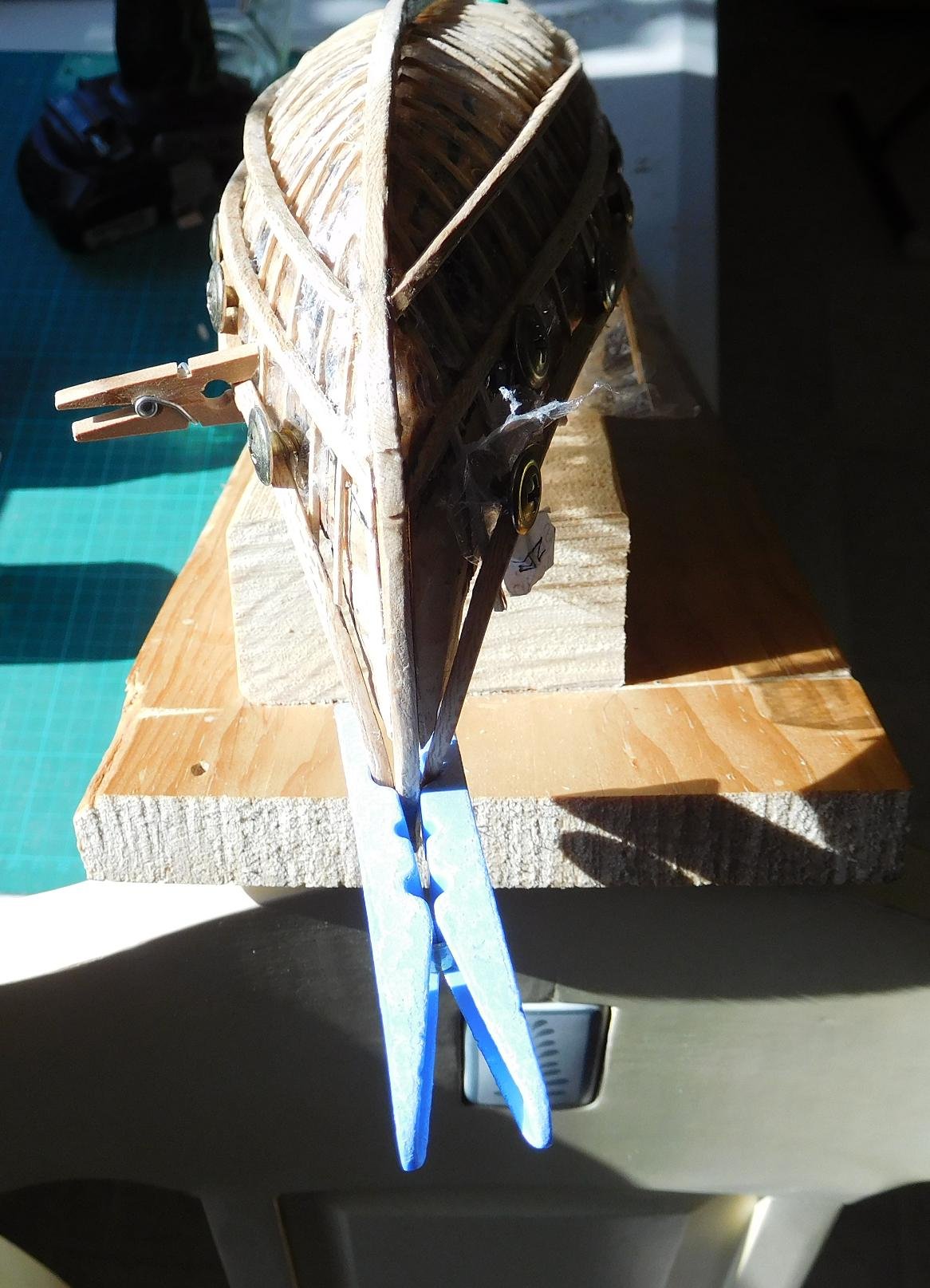
I'm pretty happy with the symmetry of the wales and the line they take. A good ship should look beautiful - the lines should be attractive to the eye. Funny, till I saw the end-on photo I hadn't notice the slight inequality in the line of the keel and stempost. I think I can live with it, or perhaps change it a bit. (On looking at it again, it turns out to be that the keel and the stempost are a bit too big in the vertical direction where they join - I've trimmed down the join and it looks better now).

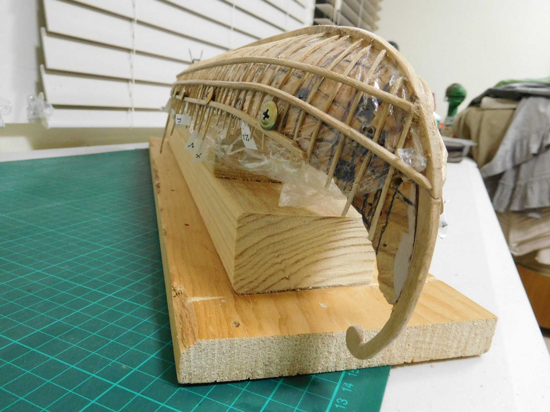
And here she is with both gunwales dry-fitted and held in place with screws (the bulldog clip is holding yet another vagrant frame in place while the glue dries).
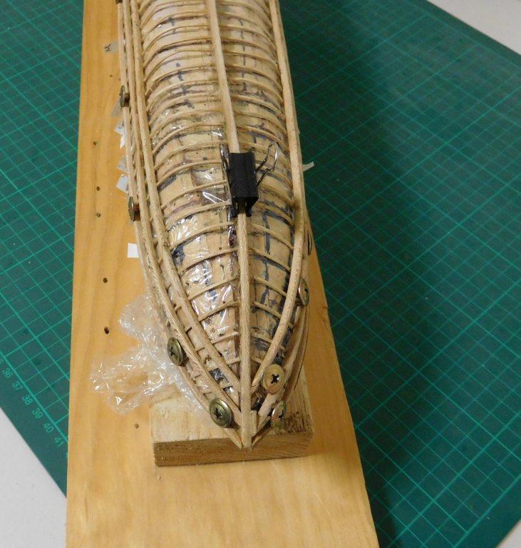

You can see from the bow view that the starboard gunwale is just a little too short. I cut it to length then discovered that the wale was a little out of place in the middle. When I adjusted it, the length was now too short. I've put in an extra piece of wood to fill the gap, which I'll carve to follow the shape of the gunwale. As I'm planning to paint the model, it won't be visible when she's finished.
The gunwales are in two pieces - one runs most of the length of the hull, the other is not in place yet - the "tail" which is a tight curve as can be seen at the stern and will be fixed to the main part of the wale with a scarph joint.
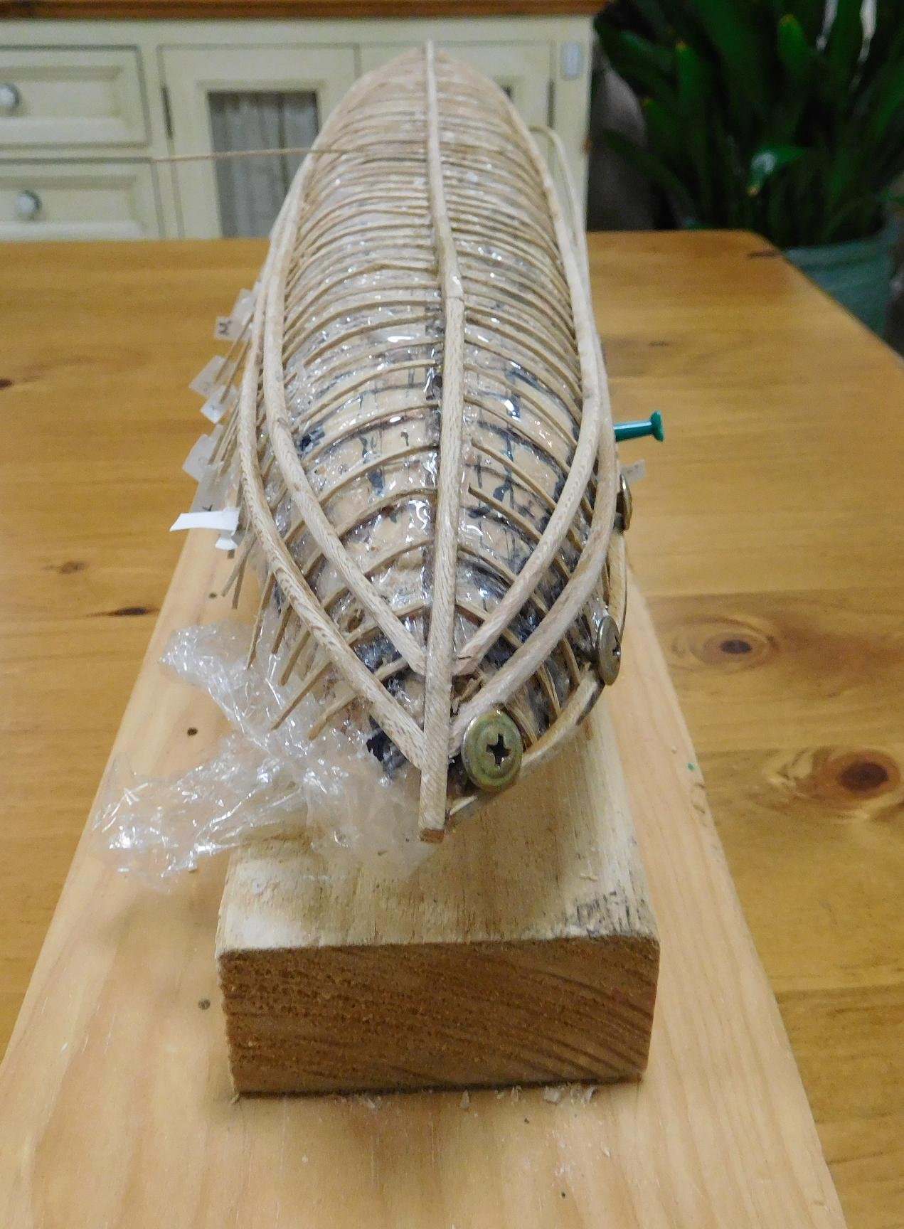
An interesting thing that I thought might happen - when I released the push-pins holding the ends of the frames to the plug, their natural springiness pushed the gunwales outward, even though the frames are only 1mm square in section. But after all, the wales are only 3mmx3mm, so they're not all that resistant to being bowed.
I've worked out how I can fix this. The ship is to be fully decked, so the deck beams will act as transverse braces to pull the wales back into place (I'll have to make a jig to hold the hull in shape while the glue dries). But I don't want to put the deck beams in until I've done some work inside the hull - in particular making a framework to hold the lower bank of oars in place and putting in the mast step(s). The extra bow is only about 3mm (1/8") on either side, so it's not as serious as I feared, and may not affect the work I need to do before the deck beams go in. If I'm worried about it, I'll make some temporary braces to hold the gunwales in place while I work inside the hull.
Overall I am very pleased with the way she looks, particularly with line of the stern. I think she's going to be a very beautiful model.
Steven
- CaptainSteve, hexnut, woodrat and 7 others
-
10
-
Very nice, Dick.
Did you do the cross stitching with a stylus of some sort?
The example above has painted decoration on the sail, which seems to have been fairly rare, but not unknown. Are you planning to do any on your own nave's mainsail?
- cog, CaptainSteve and mtaylor
-
3
-
Nice work, Rick. The Enterprize is a great first scratch build. Not too difficult, but with plenty of challenges. I like your workmanlike approach to fixing things that didn't quite turn out right - just fix it and get on with the build.
I think I saw the full-size Enterprize not that long ago in Geelong. She's a beautiful vessel, but I hadn't realized there was so much of her below the waterline!
Enjoying watching your progress,
Steven
- mtaylor, vossiewulf and Omega1234
-
3
-


Cocca Veneta by Vivian Galad - Corel - 1:70 - modified
in - Kit subjects built Up to and including 1500 AD
Posted
Hi Vivian,
You certainly don't need to follow Corel's white painted lines. They don't appear in contemporary paintings of coccas - look particularly at Carpaccio's St Ursula series of paintings for extremely good representations of these vessels.
I think I've read that paper of Valenti - very impressive.
And if you want to get rid of a mast and make other changes to make it closer to a late 15th century ship, you could end up with a very good model indeed.
You're making good progress with the build, but may I put in a suggestion? I really have trouble with the shape of the bow on the corel model - I don't believe the bow should be inclined backwards as it is. I know it's on the votive model, but I think the modelmaker got it wrong - and Corel have inclined the bow even further. Look at contemporary pictures and I think you'll find a more believable bow shape.
The trouble is it might be too difficult to change the model's central "spine" to a better shape at the bow - and you'd probably have to make the foremost bulkhead narrower as well, but you've already glued it in place. I was going to mention this before but wasn't sure if I should, as it might sound too much like criticism. And you've gone ahead so fast I don't know if it could be changed now.
But if you're prepared to do it, I think it would make a more accurate representation of a ship of the time.
Steven