SketchupModeller
-
Posts
80 -
Joined
Content Type
Profiles
Forums
Gallery
Events
Everything posted by SketchupModeller
-
 Chalk up another 'gotcha' with the bitts. Very cleanly done, nice work.
 -
As long as the photos are relevant to the original topic, I don't see a problem myself. i.e. offering a solution to a problem - fine (and likely appreciated), starting your own build log in another person's - not so good.
-
what powertools to buy
SketchupModeller replied to Adrieke's topic in Modeling tools and Workshop Equipment
From what I've seen, a drill press stand seems to be quite a versatile tool; I've heard of people using it for a small lathe, thickness sander, mill, oh and I almost forgot that it drills holes too -
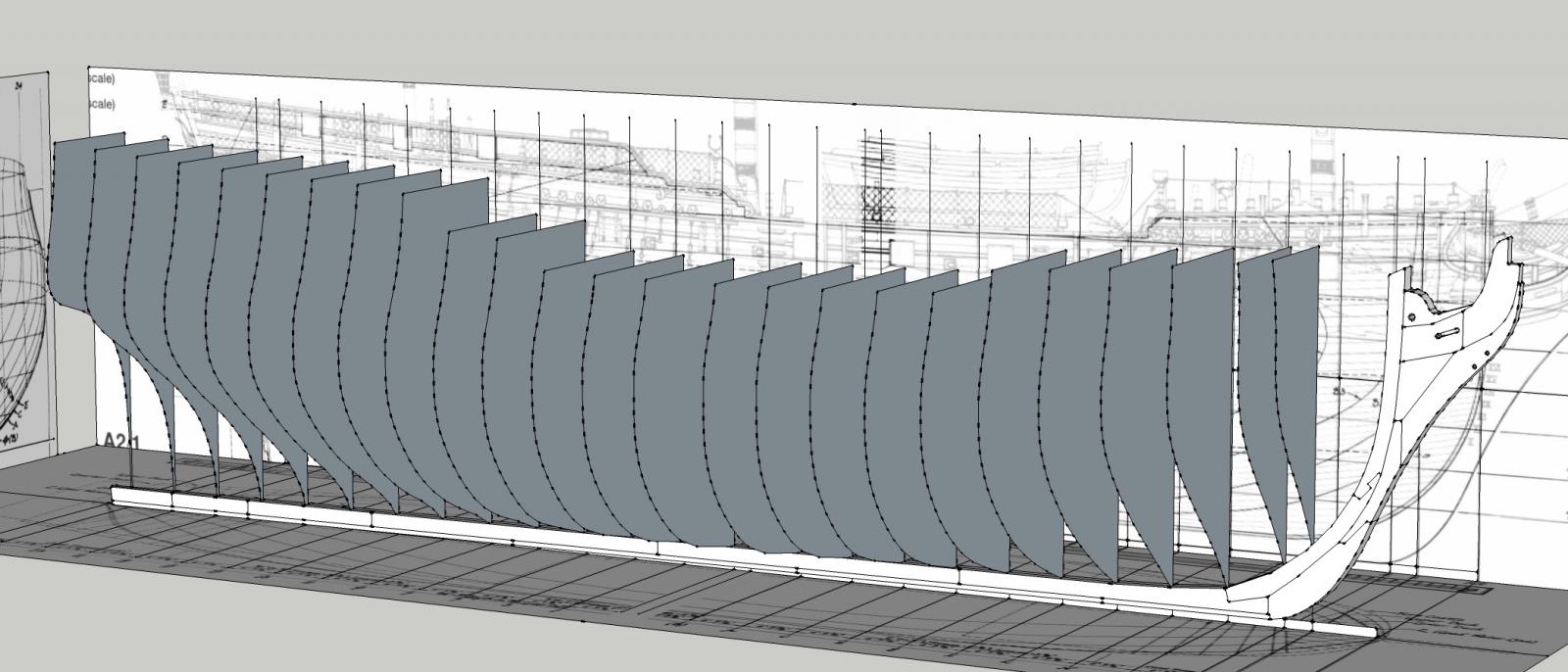
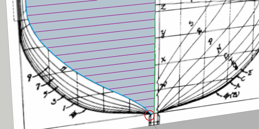
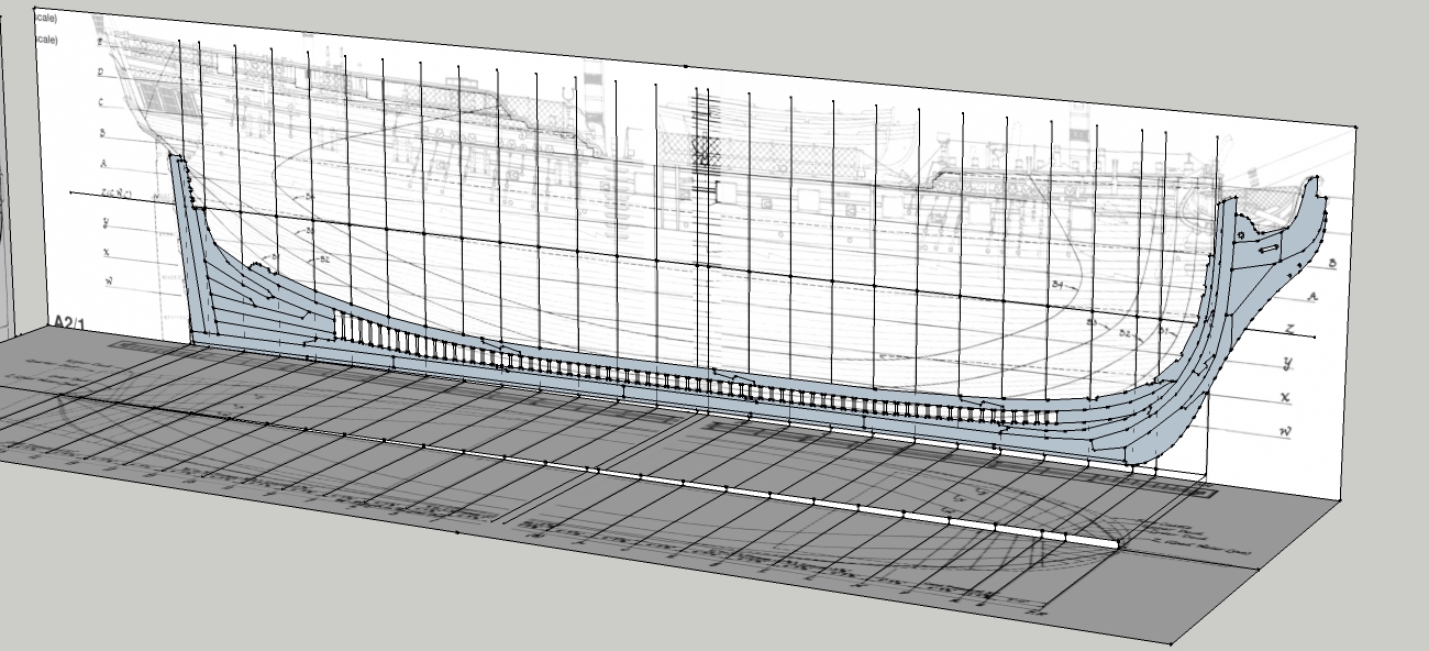
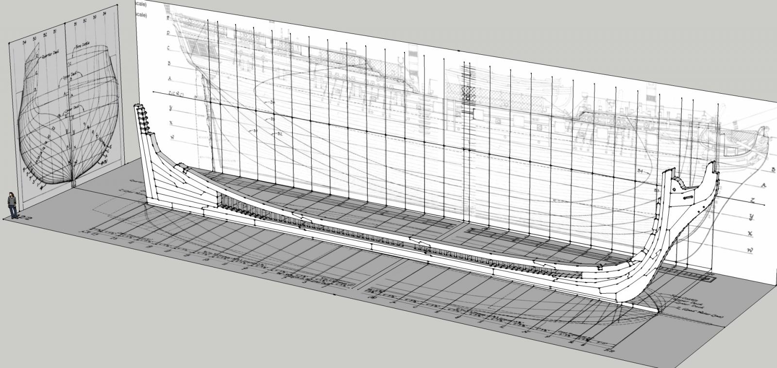
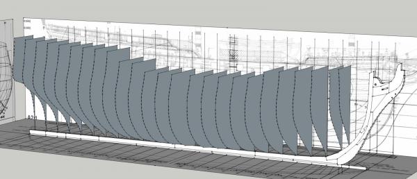
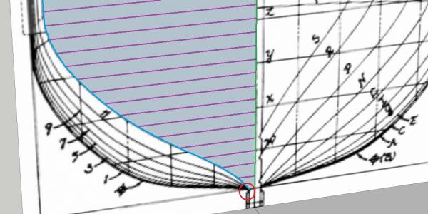
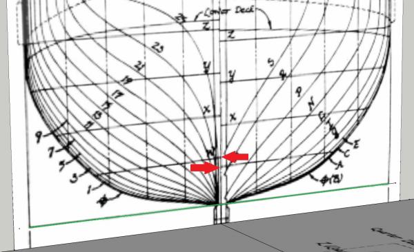
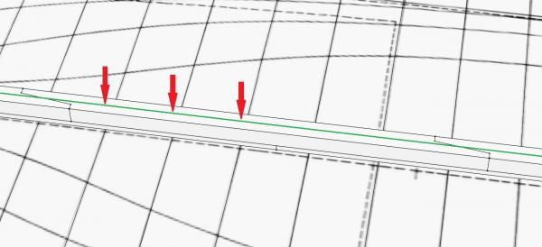
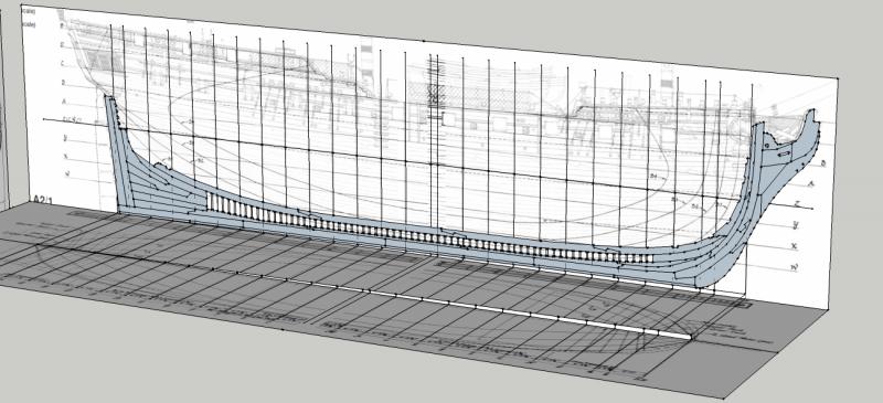
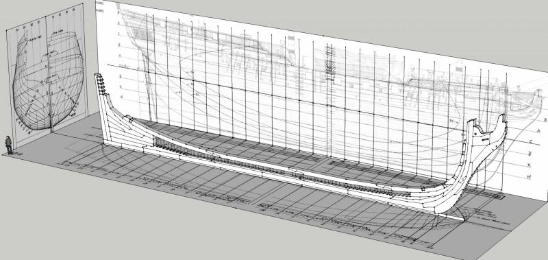
Part 5: Tracing and Placing the Station Profiles This update will cover the process of tracing and positioning the profile of each station, in preparation for creating the first surface that will define Pandora's 3D shape. As a note, the portion of the ship aft of the last station will be dealt with by a different method, which will be discussed a bit later. As can be seen below on the body plan, the stations are aligned at the top of the keel (green line). Since the keel is not horizontal on the ship, the waterlines follow a curve - note how waterline W touches the centreline at two points (red arrows). As result, it is much easier to use the keel as the reference line. After all unnecessary parts of the keel assembly were hidden, a centreline (green line in the picture below) was drawn on top of the keel and marked at each station (red arrows). This was done for the entire length of the keel. At this point, I can start tracing the profile of each station. Here, I'm using station 13 as an example. Starting at the reference line, I mark the vertical centreline every 12 inches (green lines), and draw a line laterally (purple lines) to the station line. Once this has been done for the entire station, it's a simple matter of connecting the dots (blue lines). Because the lines I'm tracing here represent the inside edge of the planking/outside edge of the frames, they will also form part of the rabbet. Taking this into account, the lowest line was connected to the keel a few inches in from the edge (red circle). The final profile is composed of at least 25 segments, reasonably approximating a smooth curve, although there were a few areas where it was necessary to add extra points. Given the fuzziness of the scanned lines, I only measured to the nearest 1/4 inch. Once this was done, the horizontal lines were erased and the final shape was copy/pasted into position on the points previously marked on the centreline of the keel. When every station had been completed, the model looks like this. The next few posts will define the stern portion of the ship and convert the lines shown here into a surface.
-
FYI, the instructions are available on the Model Expo site, but in black & white and with lower resolution pictures.
-
Another odd point I noticed was that all the frames were doubled except for the part closest to the keel. I'm curious whether this was common practice as well.
-
HMS Pandora 1779 in 3D
SketchupModeller replied to ppddry's topic in CAD and 3D Modelling/Drafting Plans with Software
Bernard, that's a brilliant presentation you've made, and -
Air brushing
SketchupModeller replied to wthilgen's topic in Painting, finishing and weathering products and techniques
If you're using lacquers or oil-based paints, a mask may not be a terrible idea, but acrylic paints, especially when used in a spray booth, aren't as hazardous and don't require a mask. -
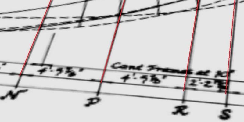
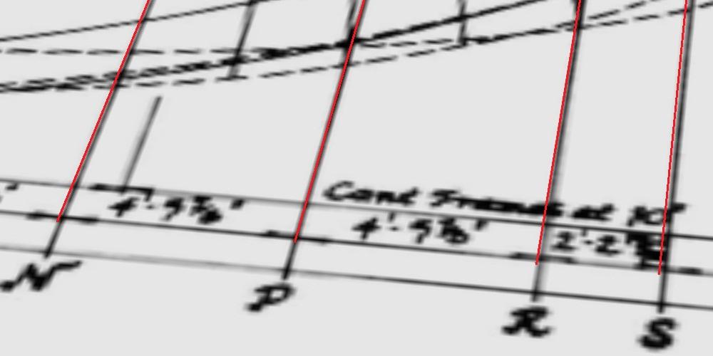
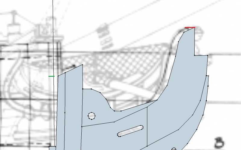
Part 4: Keel Parts and Keel Errors? Now that the plans and reference lines are in place, I can start drawing in the ship. My approach, unline ppddry's, is to convert as much as possible directly from the source drawings to the 3D model without a complete 2D CAD step. I may revisit this approach. I started the keel assembly by importing and scaling McKay's drawing of the keel (drawing B2 in AotS Pandora). This was traced and aligned with the plans on my work surface, as shown below. As a note, the lines between the keel and the keelson mark the edges of the frames But there's a problem: looking at the next picture, we see a six inch difference (red line) betweehn where the foremost part is and where the body plan says it should be. What happened? On other error, illustrated by the green line, is a four inch difference between the plan's fore perpendicular and the line drawn from the fore perpendicular at the bottom of the plan (i.e. the line I use as the fore perpendicular). This suggests to me that the scanned plan is skewed slightly to the left, and thus not completely accurate (the horizontal lines on the plan are actually horizontal). For this reason, I will consider the traced keel to be correct. Having decided that my work to this point was not completely wrong, I brought the keel to the centreline and extruded most parts to the full thickness of the keel. A few parts, specifically the sternpost, aftmost piece of the keel proper, and some of the stem pieces, were tapered in accordance with McKay's drawings. The rest of the shaping, including cutting the rabbet, will be done later.
-
Charles W. Morgan Restoration Shipwrights Blog
SketchupModeller replied to trippwj's topic in Nautical/Naval History
This also shows how big things are (planks, trunnels, etc.) in real life. -
One point that needs to be made to those of you considering Sketchup is that the program, as downloaded, does not have the tools to work efficiently with curved surfaces. However, there are a number of plugins that can be downloaded separately to help with this. Curviloft is a package that includes a few different types of lofting tools. Joint Push Pull is another package that includes a few different tools to extrude a curved surface out (to give thickness to planking, for example). Finally, bezierspline is a set of tools that allows you to draw a variety of splines and curved lines. In general, any plugin authored by Fredo6 (including the three I've just listed) tends to be very useful. A list of plugins, including a number of rendering options, can be found at the Sketchup website here: http://www.sketchup.com/download/plugins.html#ruby A wide variety of plugins, including a number of drawing tools, can be found here: http://rhin.crai.archi.fr/rld/plugins_sections.php
-
HMS Pandora 1779 in 3D
SketchupModeller replied to ppddry's topic in CAD and 3D Modelling/Drafting Plans with Software
Wow! That's amazing... -
I hadn't seen this before either. It almost seems like the image in a child's mind as he plays at being a pirate.
- 33 replies
-
- 2
-

-
- trinkstein
- frigate
- (and 2 more)
-
Welcome to MSW ppddry. I'd really like to see you start a log of your Pandora.
-
I don't think it would be that hard to make this yourself. Trace a french curve template onto a suitable piece of plastic, cut it out, and get back to shipbuilding.
-
Brilliant! I really like the way the bucket handles worked on the poop rail.
-
Panthere 1744 in 3D
SketchupModeller replied to malachy's topic in CAD and 3D Modelling/Drafting Plans with Software
It looks to me that the upper of the two lines indicated by the arrow is an extension of a faint line, possibly the forecastle deck line, and the lower (horizontal) line might then be used to give the height of the forecastle at the bulkhead. Other than that, I have no idea what that line might be. -
HMS Lizard 1697
SketchupModeller replied to igorcap's topic in CAD and 3D Modelling/Drafting Plans with Software
Very nice. What software are you using? -
Very well done, I look forward to seeing Syren fully rigged.
-
Panthere 1744 in 3D
SketchupModeller replied to malachy's topic in CAD and 3D Modelling/Drafting Plans with Software
I will be watching this closely. It seems like she could carry an extra one or two guns on each side, although I'm sure her captain didn't mind the extra space! -
Echoing what others have said, excellent work and beautiful sculpting.
-
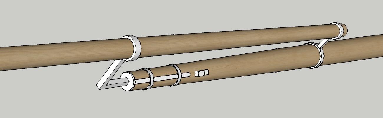
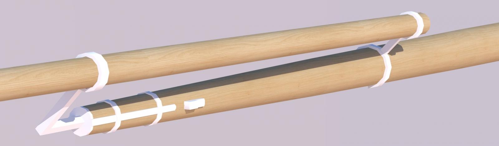
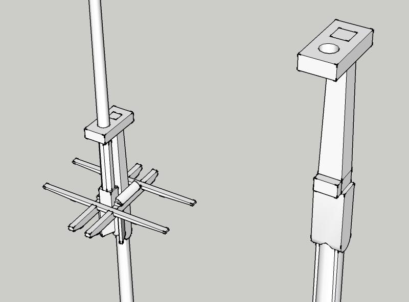
Walt, The studdingsail boom (smaller diameter yard in the pictures) would be slid inward when the studdingsails were not being used. The white objects are the boom irons, and as the name suggests, would have been made out of iron. Per AotS Pandora, the outer (boom) iron would have a roller for the boom, and the inner (quarter) iron would be made of two halves that could be unhinged, very much like the piece of metal that holds a gun's trunnion in place (neither the roller nor the hinge has yet been added to the model). From the studdingsail boom would be hung the studdingsail yard (not shown in the post above), from which would be hung the sail. I presume that the yard and sail would be taken down to the deck when not in use.
-
Beautiful model. Does anyone have any idea why the stairs would be made that 'S' shape, instead of a straight line?
- 662 replies
-
- 1
-
-
- bonhomme richard
- frigate
- (and 1 more)
-
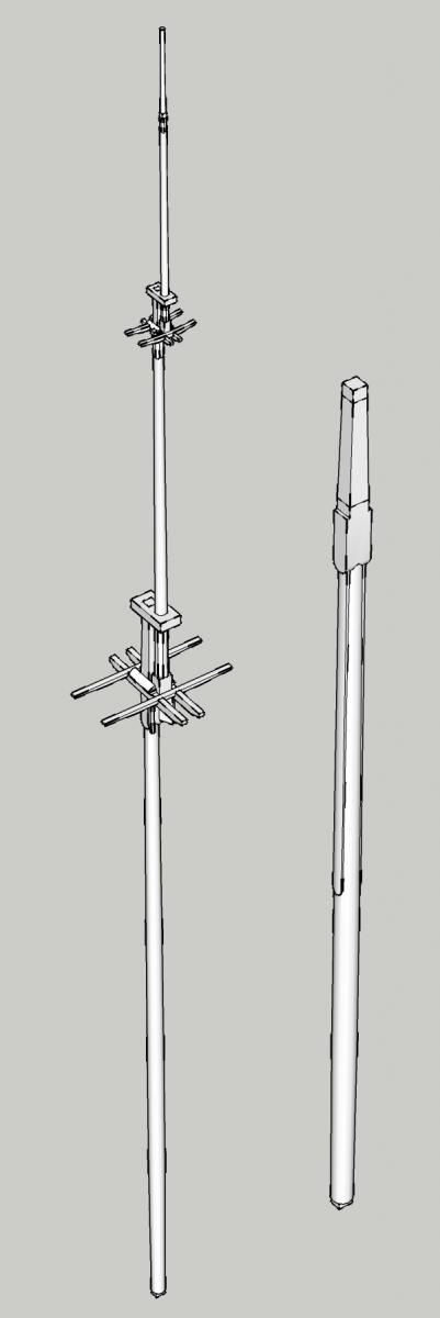
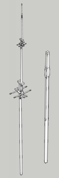
Part 3: Masts and Yards I had planned that in this update I would start describing how to build the keel. However, things don't always go according to plan. To this point, I've been reconstructing the earlier steps of this build so that the log will describe the entire process of digitally creating the model. This is a rather tedious process that doesn't seem to make any forward progress, so as a break from the tedium I've started drawing up the masts. McKay's plans for Pandora's masts and yardss include all the necessary dimensions, so I modelled these parts using the written dimensions, instead of taking measurements off the drawings. As a bonus, this is much more accurate (and less frustrating) than measuring off of drawings. So far, I've completed most of the mizzenmast (seen below, with first few parts of the mainmast) and mainyard. Some parts, such as the trees and bibbs, still need to be rounded off, and a number of details (sheaves, eyebolts, holes, and the like) still need to be fitted. As a quick test, I textured some of the spars and rendered them using Kerkythea (a program that's frequently used to render Sketchup models). I'm probably going to use a different wood texture for the final renderings, but I'm otherwise happy with the overall appearance. Below are pictures of the yardarm as it appeared in Sketchup and after rendering.


-
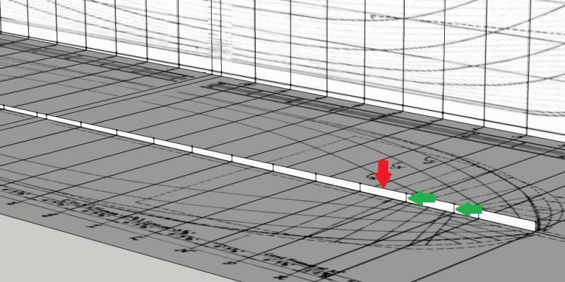
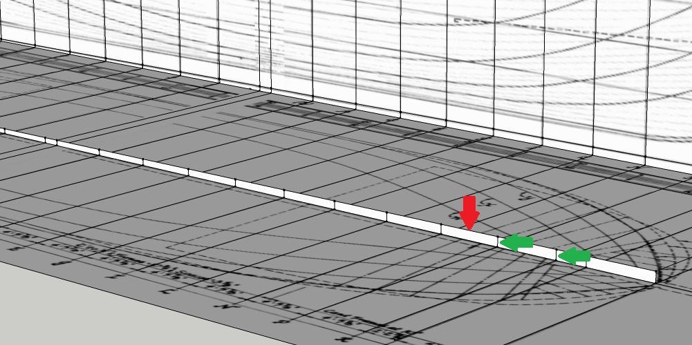
Part 2: Reference Lines In the previous part, I mentioned that I would be ignoring the station lines drawn on the sheer and lines plans. This is because the plans helpfully provide the distance between station lines. If these dimensions were not listed, I would have to go by what the lines on the drawings, which would not be as precise. Starting from the fore perpendicular, which I have arbitrarily decided to use as a reference point, I marked off the specified distances and drew in the station lines on both the lines and sheer plans. The lines highlited in red on the picture below are the ones drawn in. Note that they do not line up with the lines on the plan (black). Also note how the plans are somewhat blurry. Some of that is due to the scan, and some is an artifact introduced when exporting the image from Sketchup. Next, I drew a line following the bottom of the keel, transferred it over to where the model will be built (red arrow), and marked it with the stations (green arrows). This line will become especially important when building up the shape of the hull later on. The next post will cover setting up the keel and what to do when plans don't agree with each other.