ccoyle
-
Posts
10,605 -
Joined
-
Last visited
Content Type
Profiles
Forums
Gallery
Events
Everything posted by ccoyle
-
 I was going to mention the 1:250 card model published by Paper Shipwright and still available from them as either a printed kit or free download.
 -
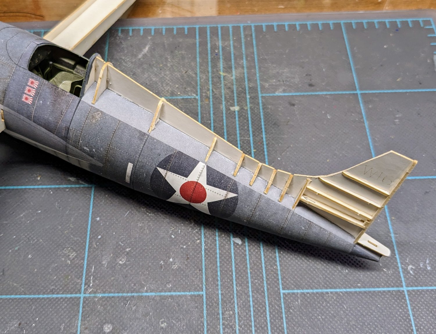
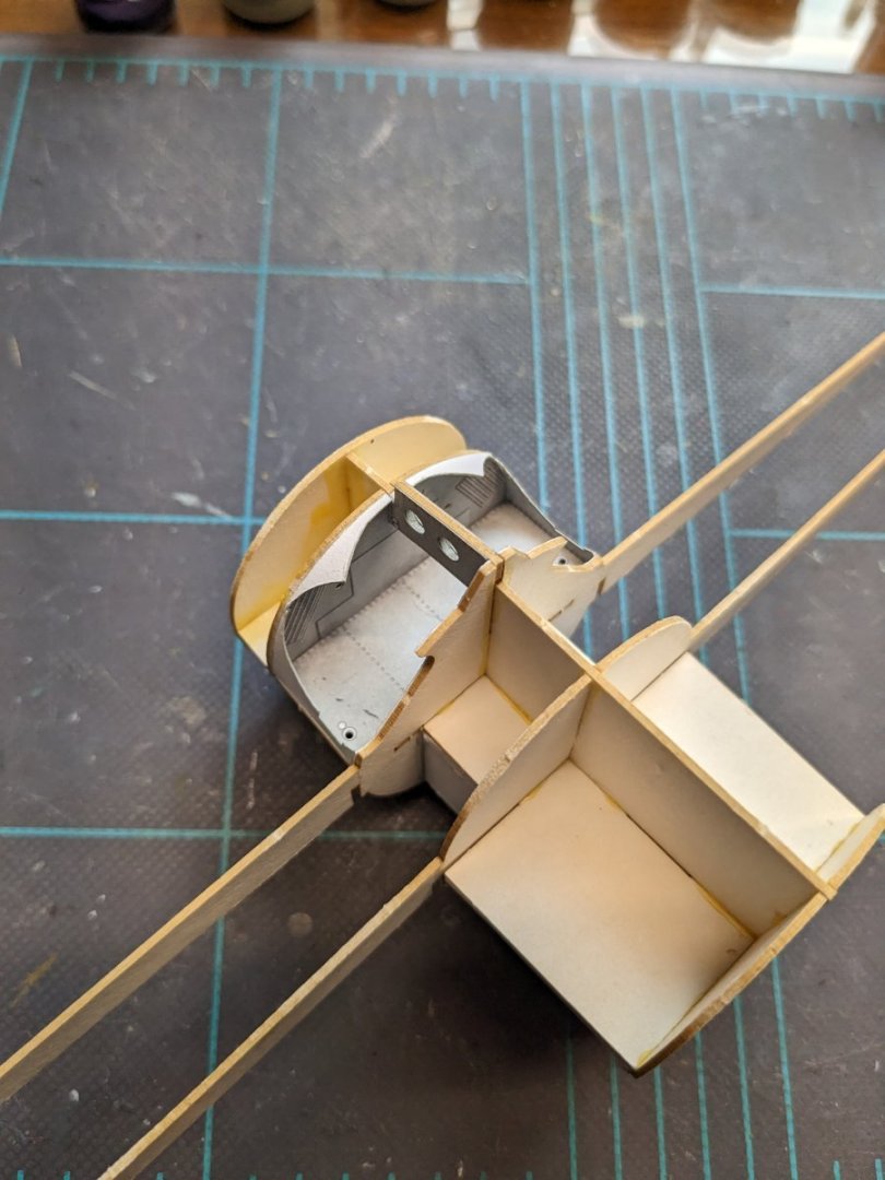
Framing for dorsal hump and vertical stabilizer has been added -- calling it a night. Not all of the transverse bulkheads come up to the height of the dorsal profile piece; I'm not sure what the deal is there, but I'll find out once I start adding the skins.
- 150 replies
-
- 17
-

-

-
Welcome aboard!
-
I have resurrected this pathetic, long-dead topic only to share with you what can be done with this very kit by those card modeling wizards over in Poland. Oh, that I should ever possess such skills! Curtiss H-75 P.S. Stumbled across that thread quite by accident while searching for info on an unrelated kit.
-
You may be able to loosen the bond with water if you used wood glue.
-
Very nice! Much sleeker-looking than a typical cutter.
- 57 replies
-
- 3
-
-
- Trial
- Vanguard Models
- (and 1 more)
-
Interesting. I always have enormous amounts of difficulty trying to stick EZ-Line with CA.
-
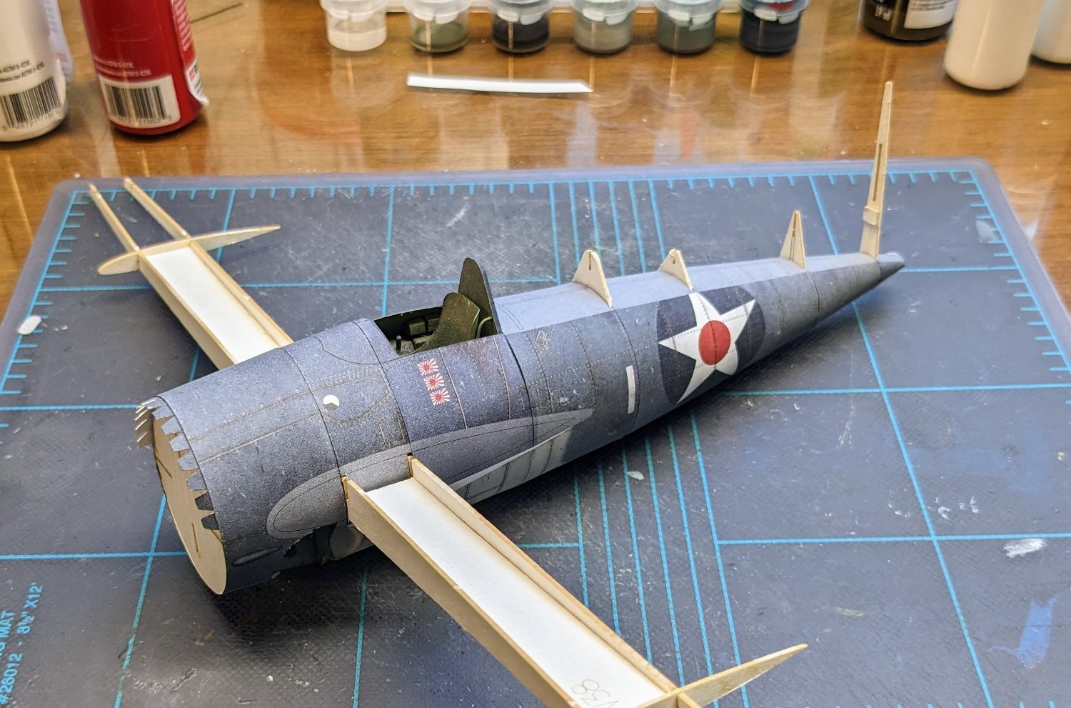
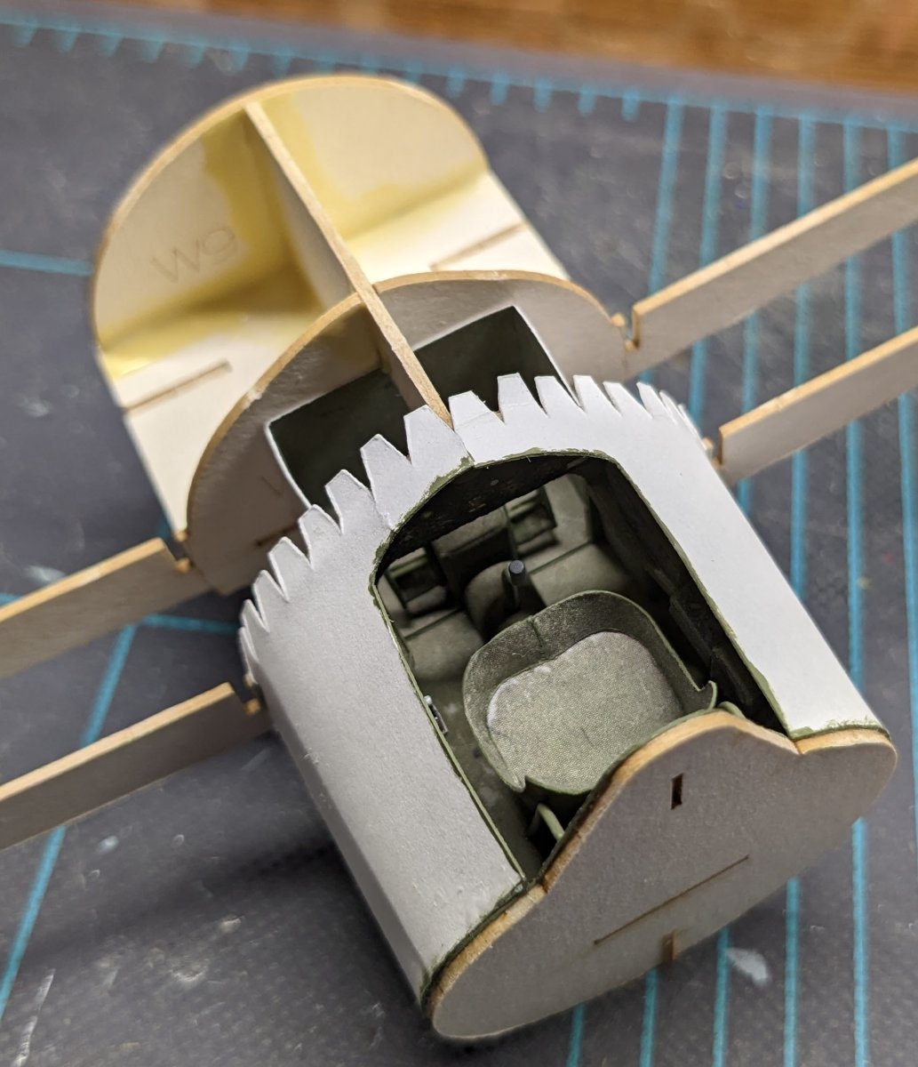
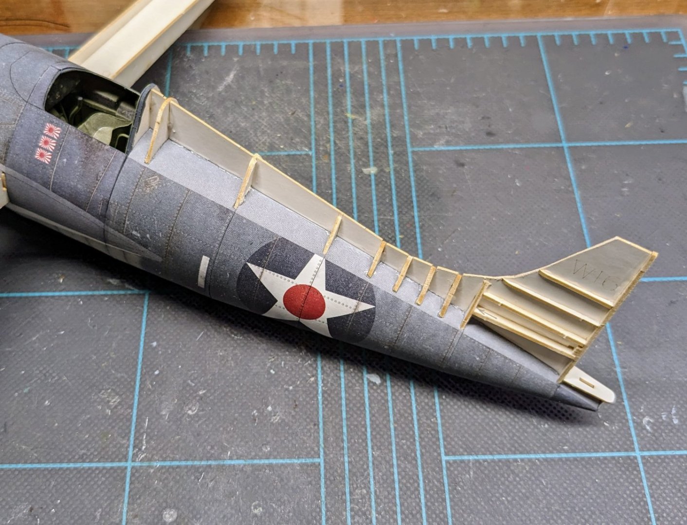
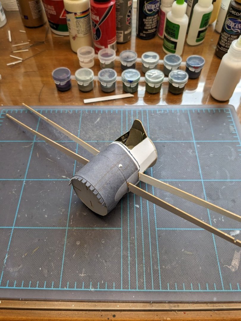
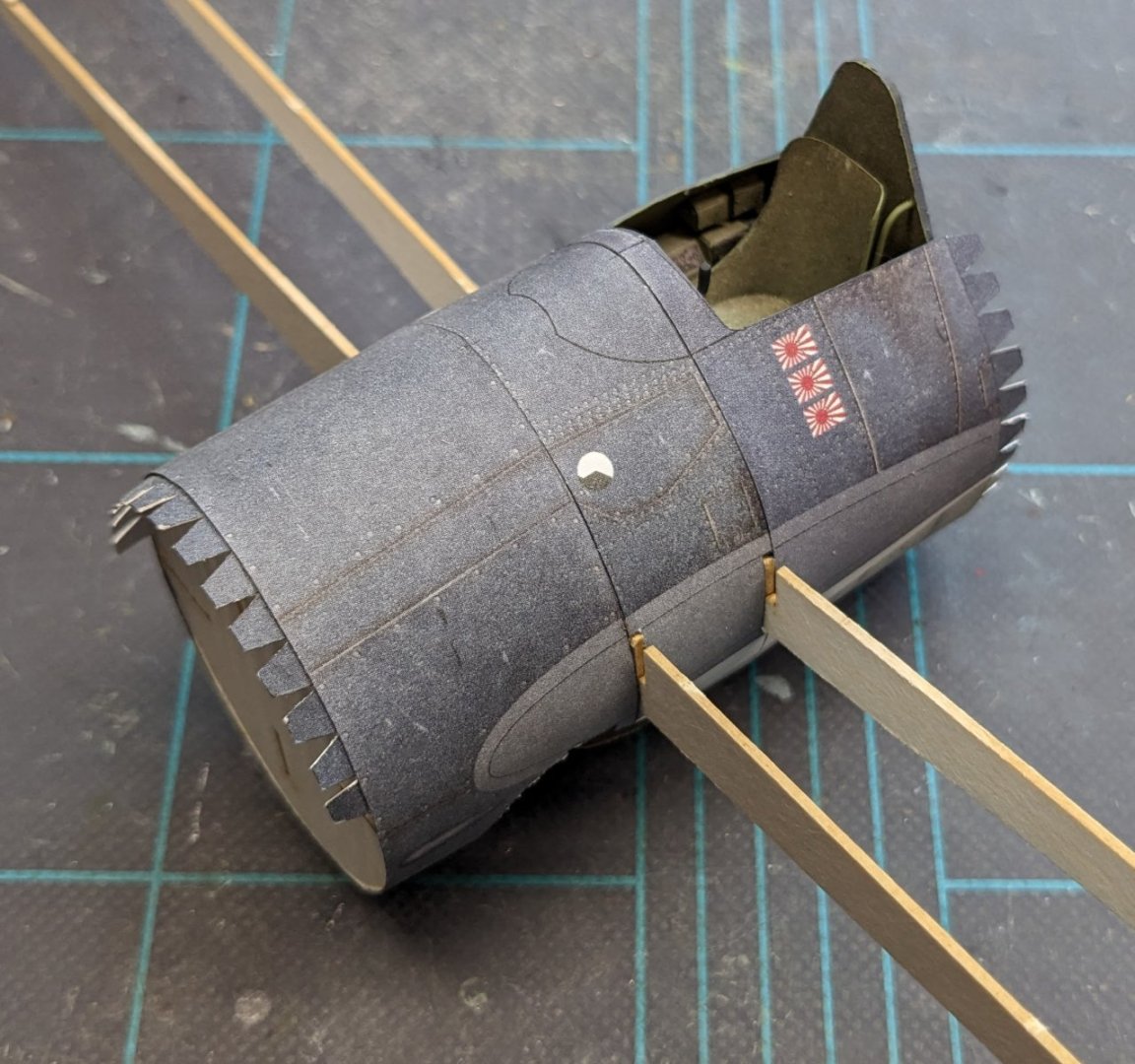
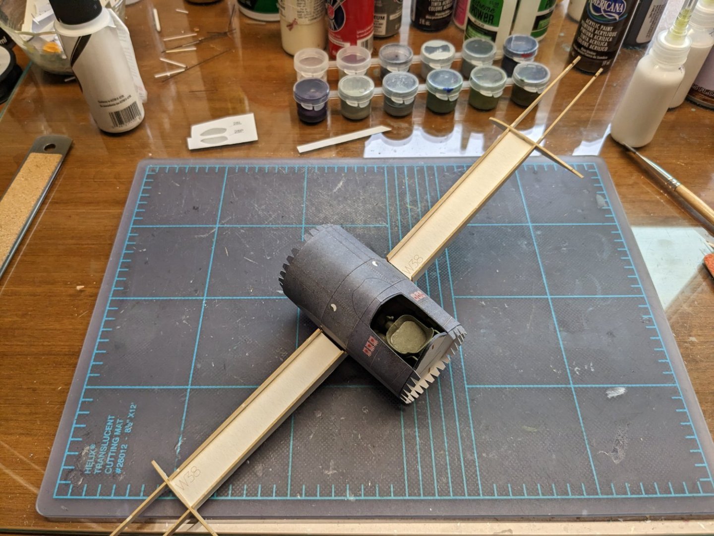
With the cockpit closed up, it's time to start skinning the forward fuselage, beginning with the wheel wells. I'm now committed to eventually building the Wildcat's nightmarish landing gear. 😬 To this point, I've been following the sequence of diagrams pretty closely, but for anyone who decides to build this kit later, it's a good idea to add the flat skins of the wheel wells before gluing the frames together. You can still do it afterwards, but it's a little trickier, because that central girder is part of one of the frames, and it clearly gets in the way. Then we have the first two fuselage skins added. Fit and registration has been good, although there seems to have been a deliberate omission of certain joiner strips. I added homemade ones -- no biggie. There's a very slight color mismatch between the second and third skins, but strangely enough it's only on one side. The parts came from the same sheet, too, so it's kind of weird. But the difference is not as noticeable as it was for the GPM Hellcat kit, so I won't complain. Once again, the fit for this part was very good. I then decided to skip ahead a bit and add some of the wing skeleton parts, just to stiffen up the spindly spars a bit. They were beginning to get uncomfortably wobbly from being jostled around. Interestingly, there are multiple errors in the numbering of these parts between the diagrams and the laser-cut frets. This hasn't been an issue so far because it's pretty obvious which parts are which and where they're supposed to go. That's all for now!
- 150 replies
-
- 17
-
-
Greg, did you use EZ-Line for the rigging? If so, I'd be interested in hearing how you go about securing the ends to their attachment points.
-
He's recommending your build log as a resource for a rookie builder working on a different kit. It's actually a bit of a compliment.
-
Moin moin, Marius! Cala Esmeralda is a beautiful ship -- I'm very fond of topsail schooners. Good luck on your project!
-
Welcome to MSW, Sam!
-
As Allan said, you can certainly spruce up your model however you like. That being said, I would probably shy away from adding ratlines. All of the sails on a small schooner could be raised and lowered from the deck -- there was simply no need for sailors to go aloft, so ratlines would look a bit out of place.
-
Hoping for a speedy recovery, Glenn. Backs are weird -- they can go out for the most seemingly innocuous of reasons.
- 587 replies
-
- 6
-

-
-
- Indefatigable
- Vanguard Models
- (and 1 more)
-
To be clear, it's not a quality issue with this kit. The kit is purposely designed for intermediate modelers, therefore its detail level is not that of a Halinski or Card Army kit, but the quality has been fine so far.
-
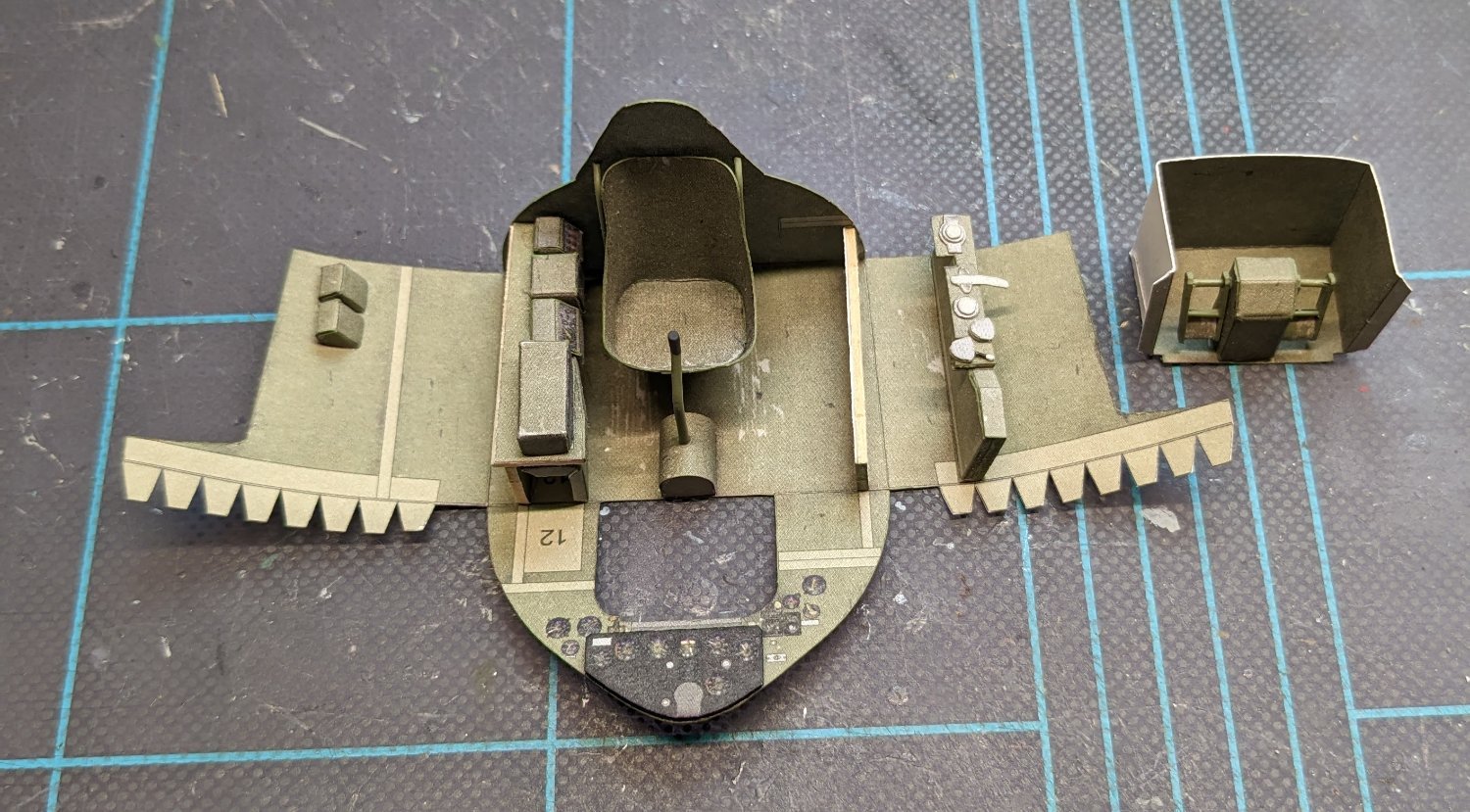
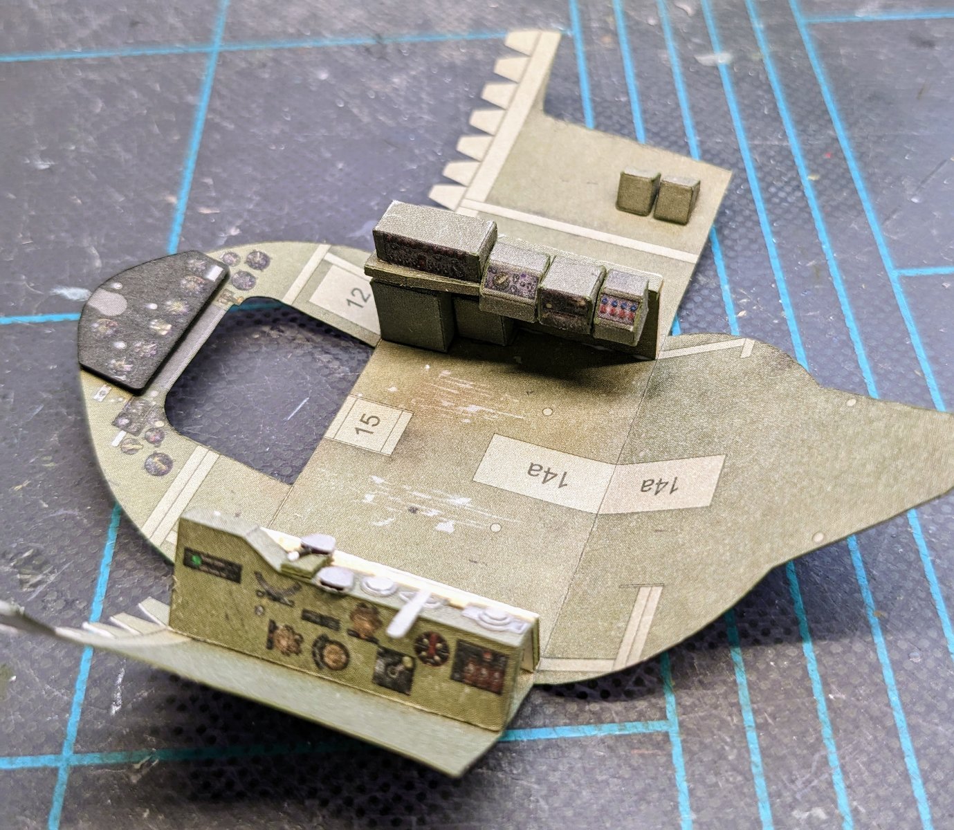
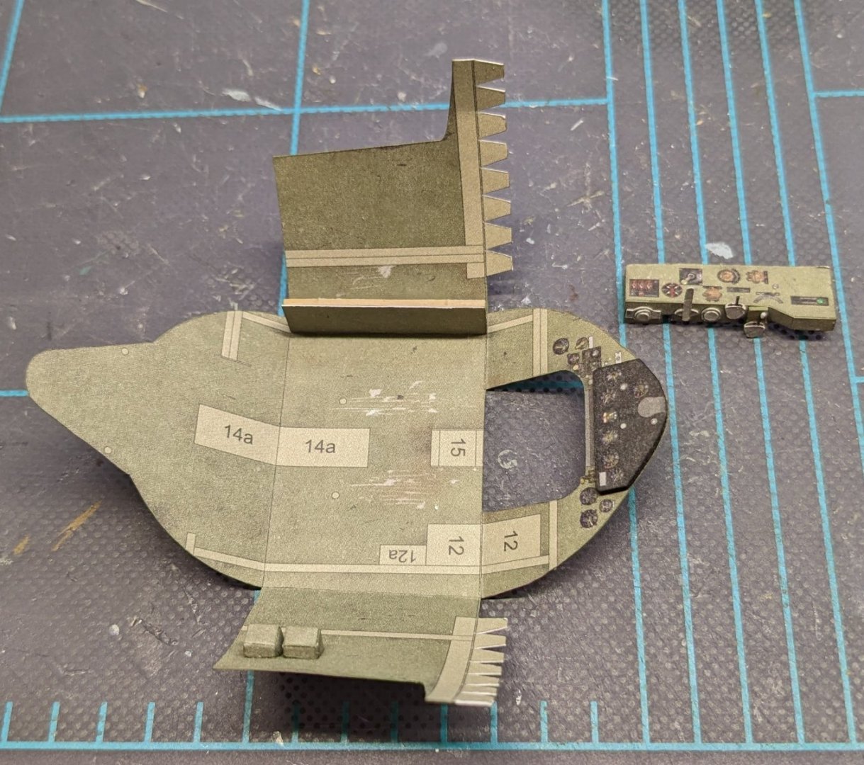
Got a smidge done so far -- cockpit bits. The intermediate-level nature of the kit is evidenced by the mix of 3-D detail parts and plain 2-D printed surfaces. No provision is made for glazing the instrument panel.
- 150 replies
-
- 19
-
-
If you want to take your oars up a notch, you can try flattening the blades and slimming the shafts. Fiddly work, but I think you'll like the result.
- 177 replies
-
- 2
-
-
- Perseverance
- Modellers Shipyard
- (and 1 more)
-
Chaz, 1/96 scale for sailing ships is a real challenge in any medium. I think you would find it very helpful to try one of the simpler free models that dot the internet landscape. You can find links in the card modeling tutorial.
- 8 replies
-
- 1
-
-
- Le Coureur
- Shipyard
- (and 1 more)
-
Mike, I'm betting those are a variant of the RAF's Mk VIII depth charge, as seen in this photo from Wikimedia.
- 75 replies
-
- 11
-
-