


bdgiantman2
-
Posts
418 -
Joined
-
Last visited
Content Type
Profiles
Forums
Gallery
Events
Posts posted by bdgiantman2
-
-
She's showing her lines and looking very nice and sleek for her size. Keep it up.
Brian D
")
- scrubbyj427 and Mr Whippy
-
 2
2
-
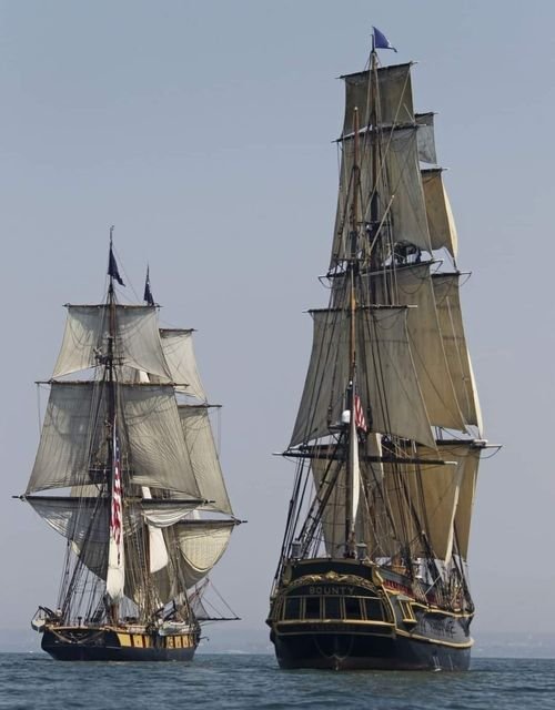
Thinking about the famous battle on Lake Champlain in September 1814 between America and the British navies, there are a lot of questions that have been running through my head. I have enclosed a picture of Brig Niagara being chased by replica of Bounty, can't tell if Bounty is still behind Niagara or alongside her. But the height out of the water is the biggest issue in question. During his extensive research, Dr. Kevin Crisman found records that Eagle had taken 39 direct hits during her battle. Most of those hits were likely along the gun deck, but probably some into the hull as well which would have to mean she was sitting higher out of the water than being shown. From the enclosed image, it would seem that Bounty would have to be tilting over to get any hits on the brig's deck. But Bounty ought to be sitting up to 3 feet lower in the water than seeing in the picture. Eagle and Niagara are both classified as shallow draft vessels, so if anyone wants to offer any insights I'd appreciate it.
Brian D
-
20 hours ago, JacquesCousteau said:
I'm curious what source you're using for Oneida being built in New York City, as I was under the impression it was built on Lake Ontario.
You are correct, I stated wrong city, but still in correct state. This is what I deserve for typing out that previous post using my cellphone after having gone to bed for the day instead of being on computer and being better able to operate multiple screens. Oswego, which is where Oneida was actually built, and on the shoes of Lake Ontario. Oswego is about 38 miles north and west of Syracuse, NY and 320 miles north and west of New York City. But I am still guessing that being in New York that the Brown brothers could have been involved.
-
The Brig Oneida was built in New York City around 1809, and Brig Syren was built in Philadelphia in 1803. The Brown brothers opened their own shipyard also in New York City around 1809, on Long Island right around what we now call the Financial district. The Brown brothers had worked for some time constructing houses, then along the way got into ship building. Also this would be the same location where those gunboat remains were found under the rubble from the collapsed World Trade towers. History isn't saying anything that I can find, but I suspect that Noah and Adam Brown started ship building with the Oneida project. Armed with experience from Oneida and drawings of Syren, America got Brig Niagara and Brig Eagle.
-
Hello everyone. I haven't forgotten about this project, despite some inconvenient changes in circumstances. I've had to temporarily shelve Brig Eagle because of change in housing situation and many of my tools had to be put in storage for a few months. However, I am still doing lots of research and making frame templates for this model to work on once housing situation improves. Lately, I've been doing additional comparisons of different ships, this time the American brigs Syren and Oneida. Syren seems more like Brig Eagle in deck layout and overall hull contours (even though Eagle is 20 ft longer than Syren and Syren was a deep water hull with additional deck like European ships HMS Blandford and Le Cygne discussed in Post 41), whereas Oneida would be more followed for rigging and was also a "shallow draft" hull design with just only berthing deck and gun deck like the Eagle was and Niagara. However, I found one article interesting about Oneida saying she was a slow performer under sail, I am guessing that she may have been top heavy for a ship her size. Will have to do more digging around work schedules.
Brian D
-
Very impressive CAD drawings of the deck gear used on Cape during her Navy days. A lot of detail, going to be fun to see how the scaled equipment turns out. As for the location of the control box, my personal opinion is it looks less out of way of operations being in front the motor between those two large white wheels instead of the offset position. This is incredibly cool.
Brian D
- FriedClams and Canute
-
2
-
On the real ship would this support structure be the forward magazine? Looks almost the right place for such a room. Making good progress, Ben.
Brian D
-
Again I find another interesting blog way too late. You guys brought up many interesting views. The iron pigs mentioned have an interesting history as you well know and document. They are poorly smelted iron often poured into molds in the ground and would get very brittle after cooling. The pigs often measured about the same dimensions as Limber boards and weighed up to 92 lbs each.
On my model of Brig Eagle, she is said to have been filled with iron pieces like the ones pictured. It's not sure how much a ship like the Eagle would have carried in the form of ballast. I've seen estimates that the Brigs Eagle and Niagara may well have weighed twice as much as the current Niagara in Lake Erie despite modifications like engines. Using the mentioned calculations of the limber boards, the distance between the masts measured 42 feet enabling 14 boards each side between masts, which comes out to one and a quarter tons just for that space.
Brian D:)

-
I received this kit close to the same time that you did. Haven't started constructing her yet with issues involving my Brig Eagle project, but also am wanting to attempt scratch build a similar design off the same plans. Will be following this with interest.
Brian D
-
Nice progress on this ship model and blog, Chris!! Those frames look well made in all directions. Question - for the water channels you have, did you use a router/Dremel to cut those out or did you make those with a table saw??
Brian D
-
On 1/22/2025 at 5:45 AM, druxey said:
Ab: you have opened a large can of worms here! The plans for Fubbs are for the rebuild of the 1720's and differ somewhat from the earlier Stuart classic yachts.
As you may know, Effie and I are working on a book covering all the yachts of the Stuart era. There is scanty hard evidence of internal arrangements. The most detailed 'plan' (and perhaps showing artistic licence) are the Vincenzo Coronelli plates of Isabella that include a longitudinal section:
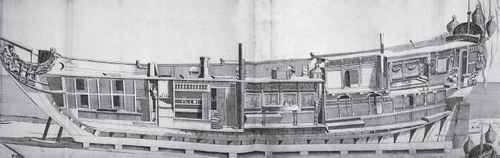
Once again, like usual, I am late to the party on a fascinating model and blog. Ab, you have made another beautiful model, I've never tried modeling with card personally. Seeing the ketch version of same ship would be really cool to me as those rigs were so rare and unique. My condolences with the many others here about the loss of extended family and your friend.
Druxey, this is great news to hear about your co-writing this book about the Stuart yachts. I have Ab's book about the Dutch cargo yachts of that time and was wondering if there was going to come a civilian/VIP version even if there is scant information available. I have long admired ships such as Mary and the Utretch. So many similarities in deck layouts and some internal features yet so many differences as well, especially length of the hull. An old book I have printed in Dutch about one of the statenjachts being built as a scale model, this one measured 79 ft long (which was recorded as a standard size of many such vessels) whereas the diving expedition to remains of Mary estimate her to be only 52 ft long. Those designs of that era are beautifully made, too bad so much history and information was either destroyed or never recorded. I look forward to this book of yours being published.
-
I know this likely isn't what you have in mind for displaying your model ships, but I saw these and the idea looks very interesting and has potential with larger models.
Got an email about this company that may be worth be checking out as well
https://www.grandpascabinets.com/
Brian D
-
I have been tempting over the possibility of starting own hobby store business in greater Denver area with a strong emphasis on ship building and hobby woodworking in general. Would also include woodburning for making kits and potentially a 3D printer. I admit that I don't know anything about CNC which some people have been making incredible items using. With permission would like to partner with certain individuals selling merchandise. Just trying to get a potential feel for clientele and overall feedback about starting up such a business.
Brian D
-
Interesting process doing the stern decorations with 3D printer, seems making headway. I may not know much about the stern designs of sailing ships from this era that the Christiana was in, but it seems most designs that I've seen in the past were symmetrical both port and starboard - likely for balance reasons and simplicity. Went back and looked at the original drawings of this ship you provided at the beginning of this blog which were less than helpful. Just my two cents. Keep up great progress on this beautiful ship.
Brian D
-
Even though probably too cold for frogs here in Colorado, I am certain that one of my neighbors has Ribbit's big cousin hanging out by their front door.
- Keith Black, tmj and Canute
-
 3
3
-
2 hours ago, moreplovac said:
Yup, it is very nice ship; regretting I had no much scratch build experience, this will be just beauty, but next one will be better...
There are many builders on this blog site, including myself, who have little to no scratch-build experience and undertake projects similar to your project and the one I am building slower than evolution. You are progressing nicely with your model, sending encouragement to you. I just hope that I can build a respectable model and like you have lots to learn ahead.
-
Phil, glad to hear that my suggestion about the Blue Jacket propeller worked out better than expected. Your progress on Cape is looking great and this has been fun to follow. As for these strips to make the sheathing, would polystyrene be an acceptable material?? This comes in a variety of thicknesses and widths, so I would think easier to work with than cutting plywood like you were mentioning.
Brian D
-
A blog I followed a while back on here was someone bravely scratch-building a Xebec, I'll have to see if still have that link attached or not. He had a spare anchor strapped solidly to that monkey ladder at the main hatch. I don't know if your plans do the same or not.
Brian D
-
Hey Brad!! Thank you for your service, and welcome to this forum! I too am in greater Denver area (close to Green Valley Ranch) after growing up in San Diego. Great job on this ship model, she turned out terrific. There is a model ship club in Denver that I am a part of (as schedules allow me) here in Denver and invite you to attend. Like you, I am super slowly working on first scratch-build project and its been a fun learning experience.
-
Nice progress on this model, you are doing great work. Were you planning to have an interior, if the kit even provides one?? The plans by Frollich I think had some interior, although items like galley are placed on main deck with that design of ship. Also, I couldn't tell from the photos provided but is the central support beam the same width as the keel? If so, that should have made lining up a lot simpler or so would seem.
Brian D
-
Those lockers seriously look like could open, but I know that just a little piece of wire placed where the hinges would be. At the scale this Speedwell model is built at, I'm sure it's only a matter of time before someone will be attempting working hinges
Brian D
- dvm27 and Stuntflyer
-
2
-
Impressive skill building those ribs so far and adding in the hawse timbers! Your Speedwell is looking great, Rusty!!
Brian D
- Rustyj, CiscoH and FrankWouts
-
3
-
-

USS Cape (MSI-2) by Dr PR - 1:48 - Inshore Minesweeper
in - Build logs for subjects built 1901 - Present Day
Posted
Great progress, I like the bridge details and the upper level plans shared on here. I thought Navy mugs were supposed to be without handles?? Or was that older times?