KeithAug
-
Posts
3,986 -
Joined
-
Last visited
Content Type
Profiles
Forums
Gallery
Events
Everything posted by KeithAug
-
 Bedford - That is how I did it last time so it is an option. It would just be sort of neat to be able to plank it. I may chicken out though.
 -
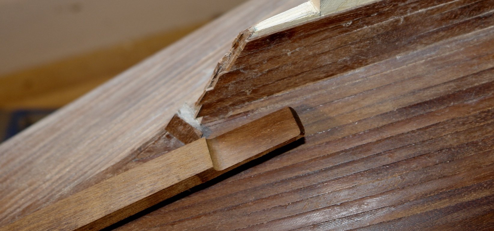
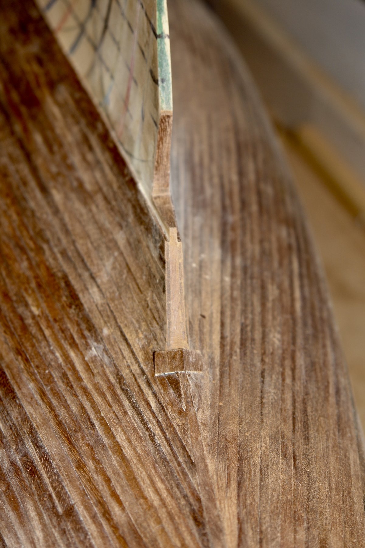
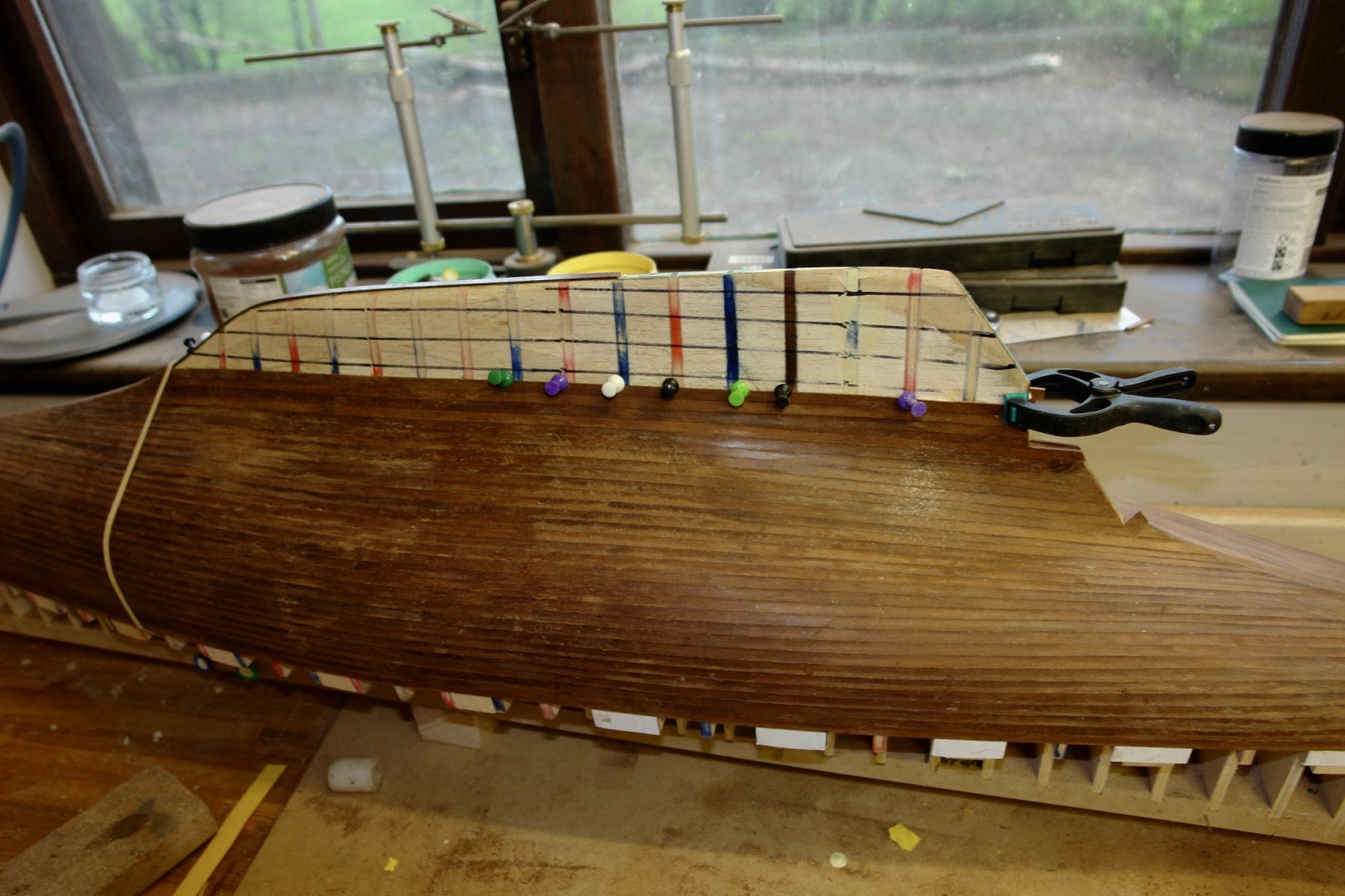
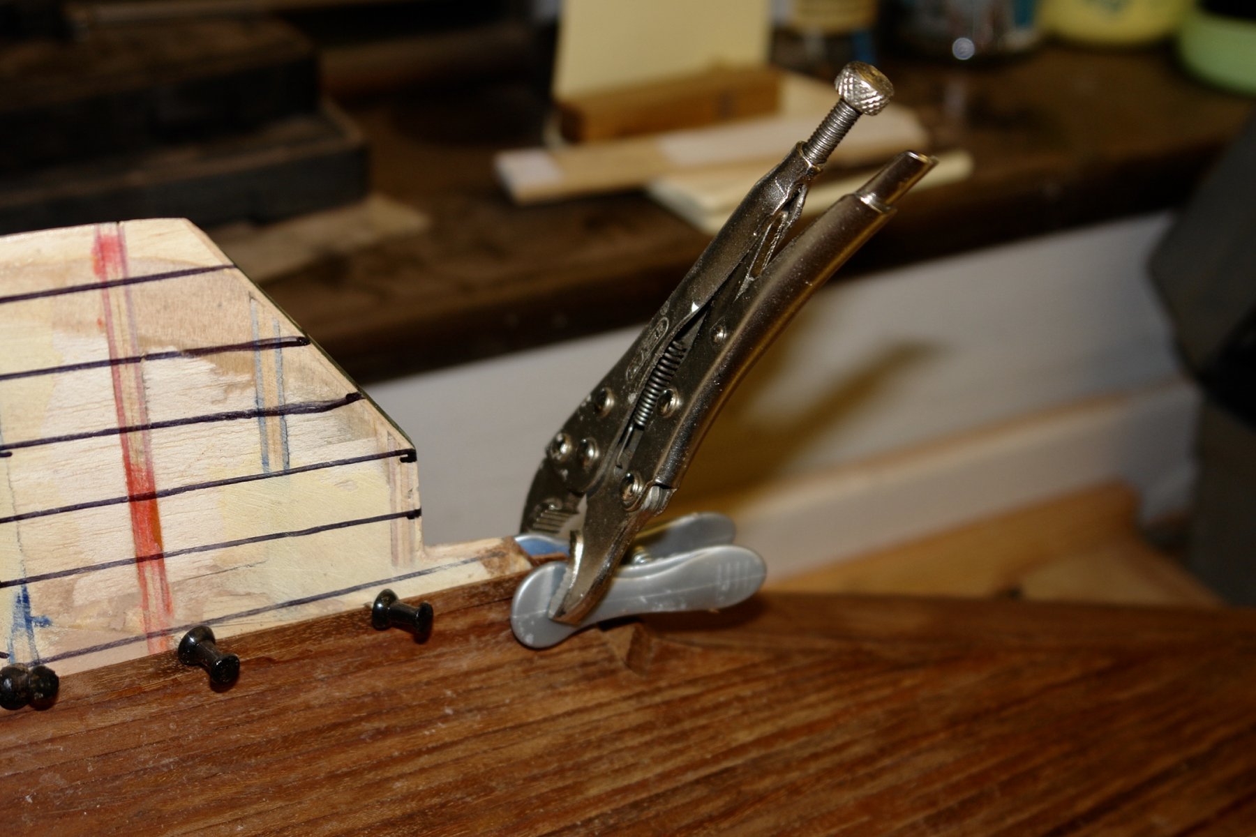
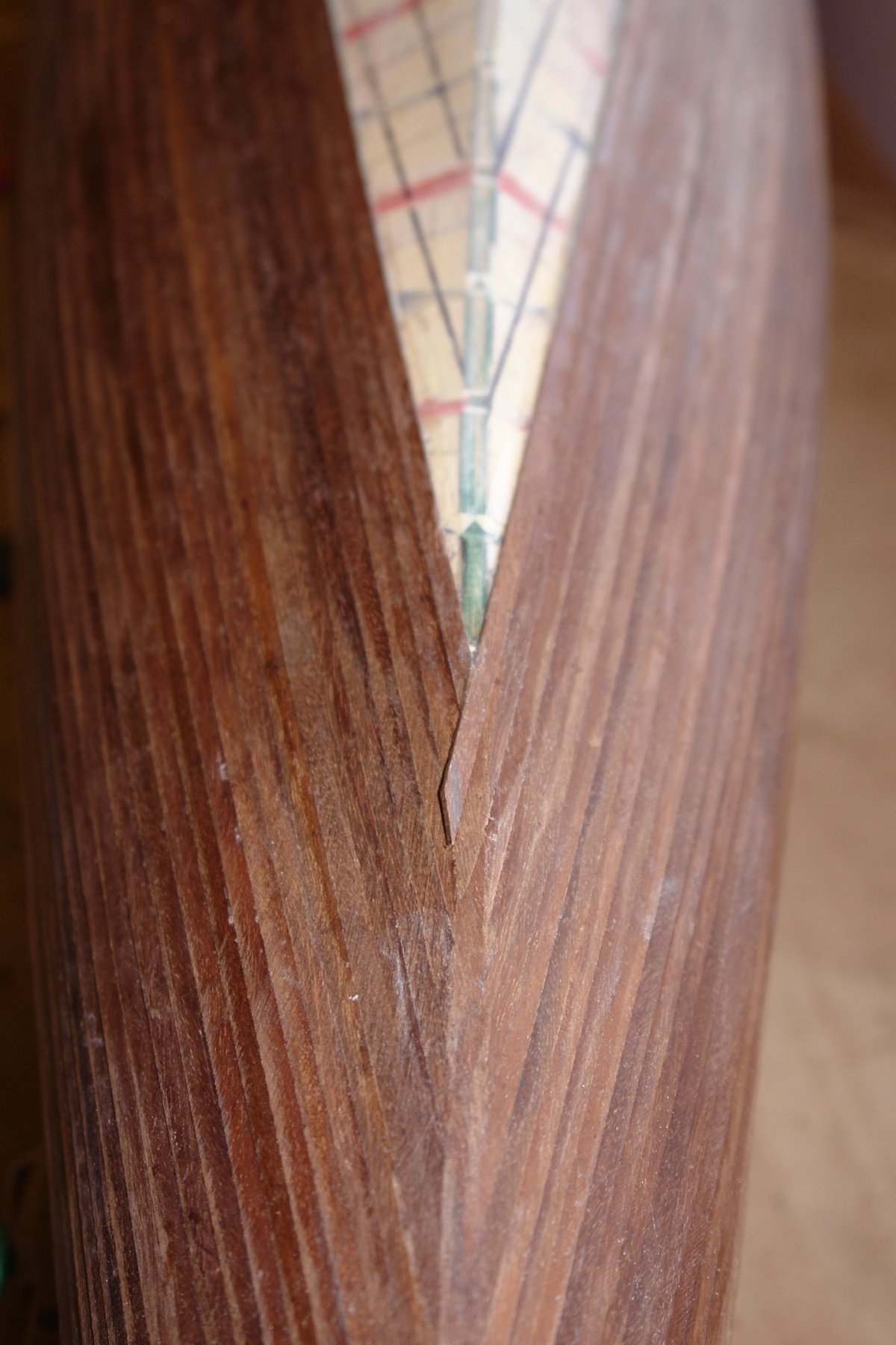
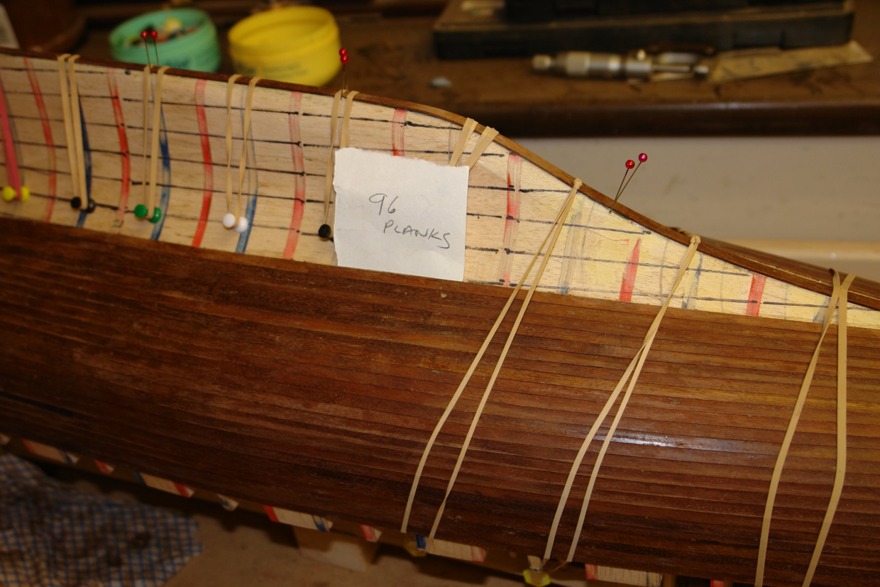
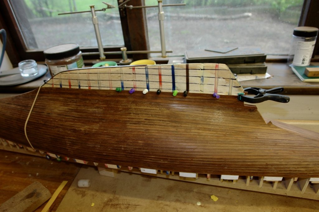
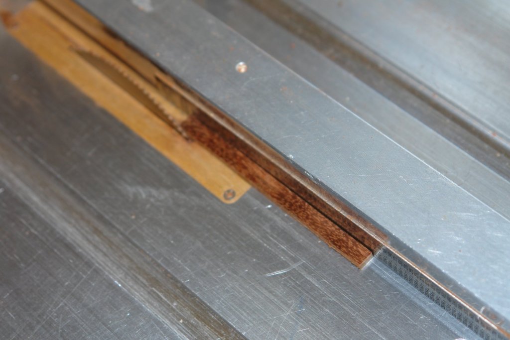
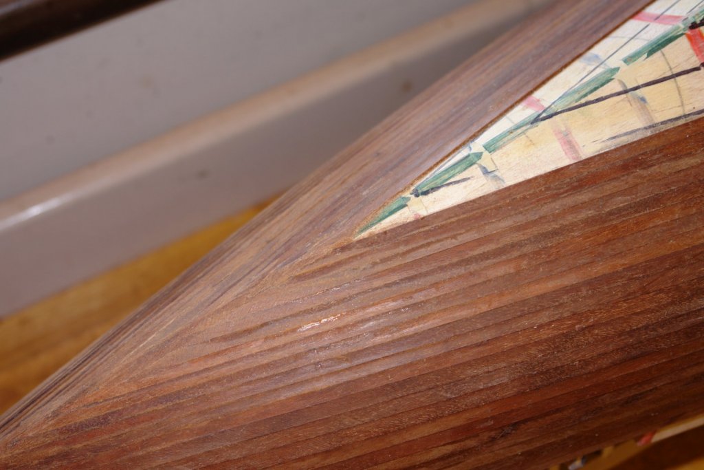
So its 14 days since I started. No dramas in the last couple of days but I didn't get a lot of time in the workshop. As I start to progress up the keel I need to sort out the cut away for the screw. In the corner it has a tight curve. I took a strip of mahogany .2" thick and used the side of a 5mm end mill to thin it down - thus creating the required corner radius - see next photo. I cut the thinned section off just behind the radius before gluing it on to the horizontal surface. A piece plank was then used to clad the vertical section before sanding back to match the keel profile. I will round off the sharp edges when I do the final hull sanding. I continued up the keel filling the back of the keel with stealers as I went. At the present time I have virtually filled the excess and the planks are now running true and virtually parallel with the deck. 116 planks have been laid. You can see the wedge planks in the next photo if you look hard. I took stock and measured the remaining area to be planked at the front and back of the keel. I will now complete the next section of planking using taper planks with a 2:1 taper. Fortunately the hull is now short enough to take single plank lengths. I also need to start thinking about how to plank the "bulb" of the keel where once again the changes in radius are pronounced. Bedford - thanks for the vote of confidence - I ,may need to draw on it when I get to planking the bulb. Vossie / Druxey - I would actually call it a Mole "WRENCH" but what's in a name.


-
Paul Actually the clothes peg (which has rubber pads) was the first clamp. Unfortunately the spring was weak and the mole grips just happened to be handy. They are the middle size of a set of 3.
-
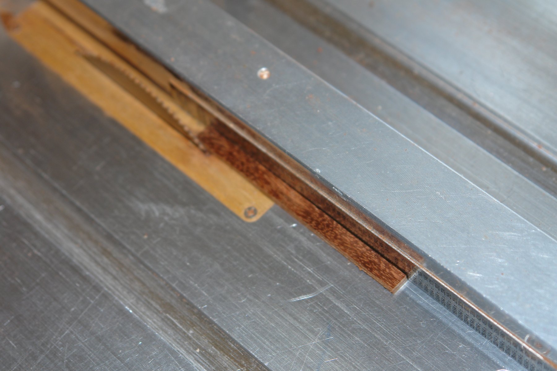
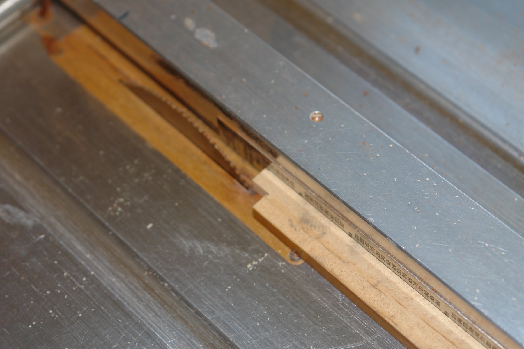
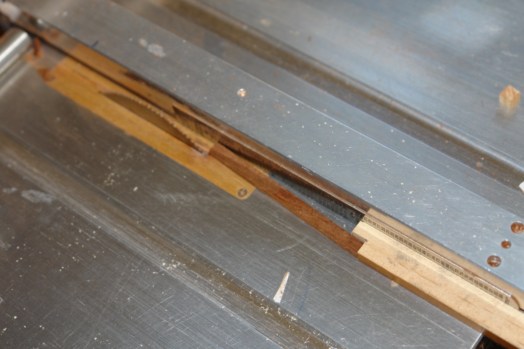
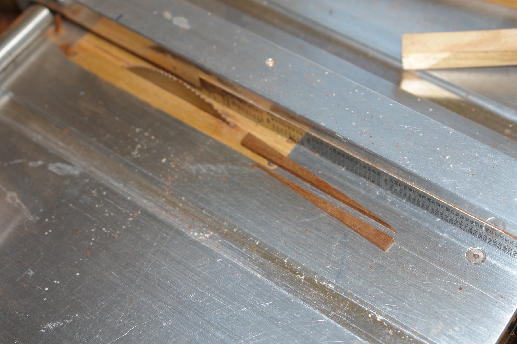
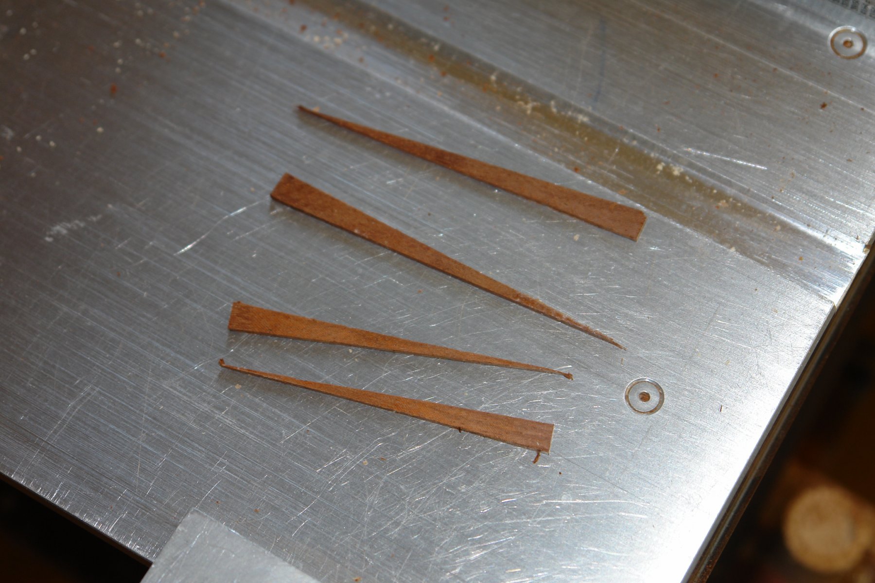
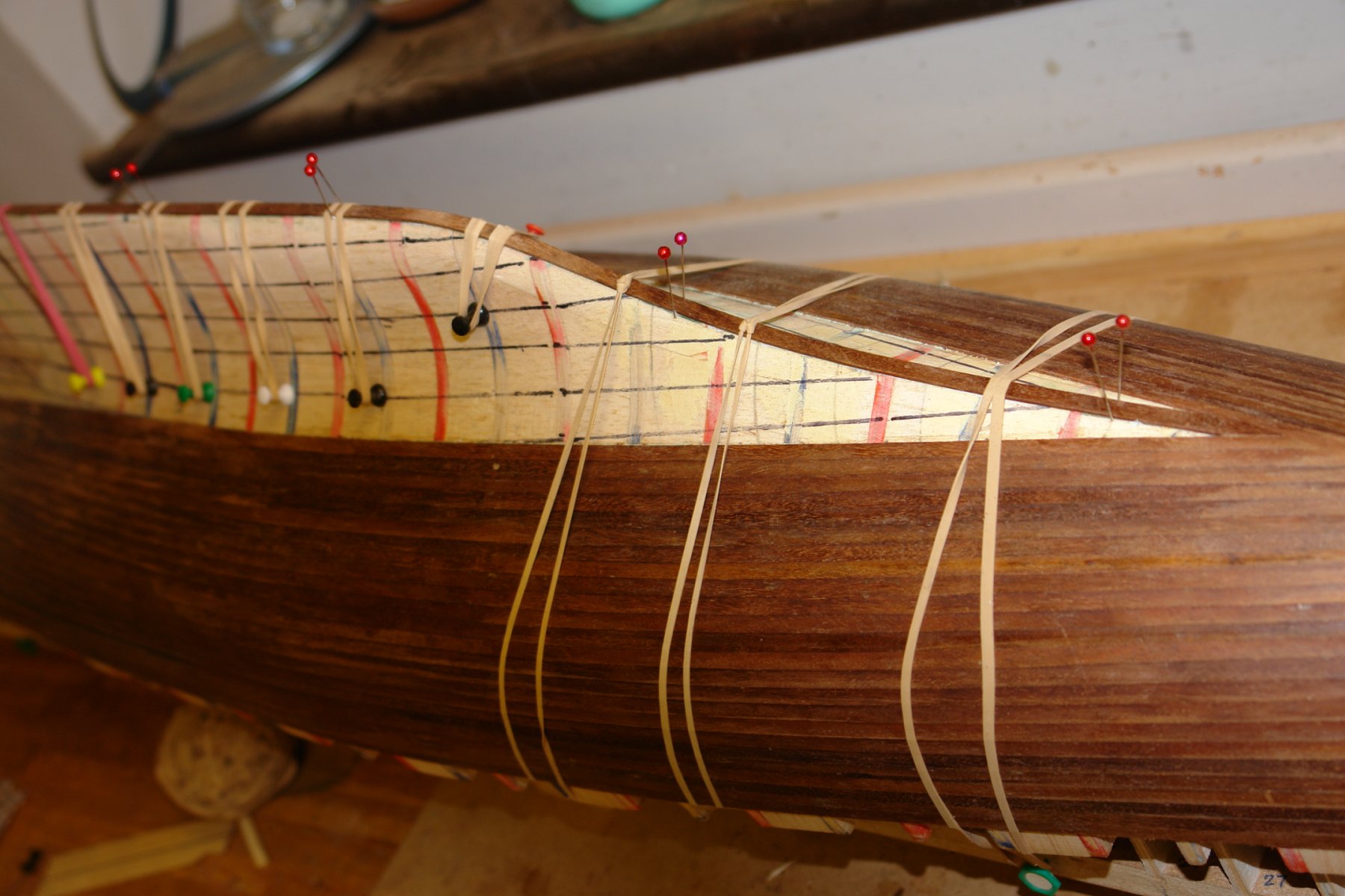
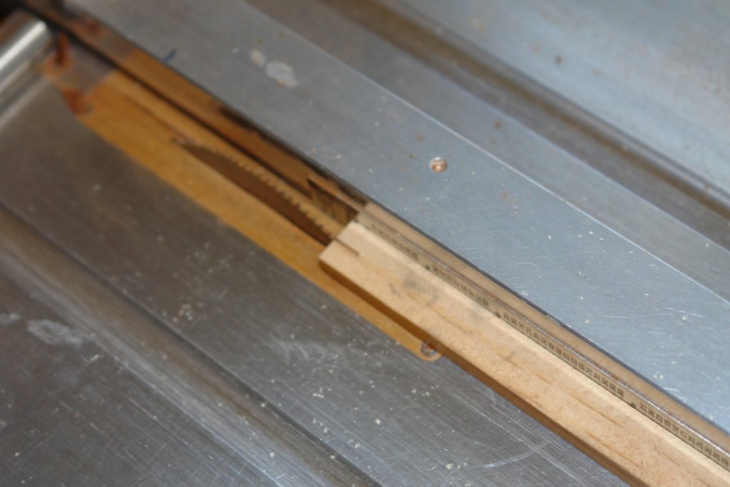
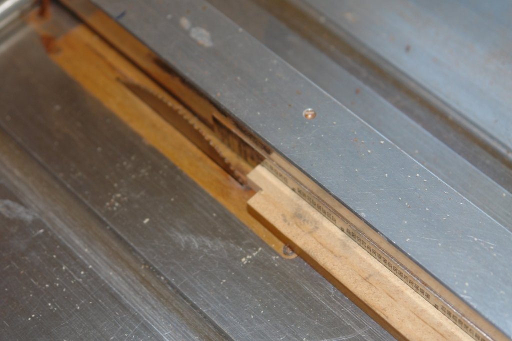
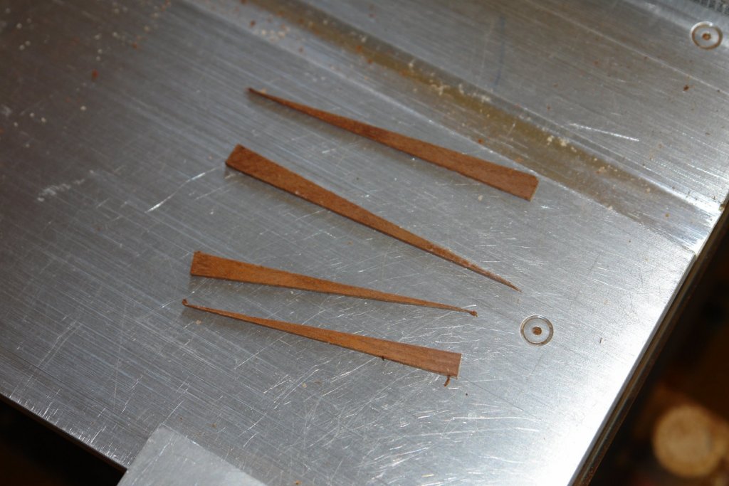
Further to the above comment I needed to accurately cut some planks to a taper of specific width and length (the measurements are taken from the hull). I do have a rip mitre gauge for the saw but I thought I would share the following method which I find easier and quicker. I set up the saw to cut the plank to the maximum width of taper needed. I then cut the plank to width. Having done this I then cut the plank to the length of taper needed. As I usually need 2 tapers (one for each side) I stick 2 planks together using double sided tape. Without changing the width of cut on the saw I then slot out the end of a piece of scrap. Having done this I create a notch using a hand saw. I then place the plank against the notch and use a push stick to apply side pressure to hold it in place while pushing the plank into the blade using the notched stick. I end up with 4 tapers - 2 correctly sized and 2 slightly smaller (because of the blade width). I know stealers are not supposed to come to a sharp point but I find they work fine on this type of hull. And so I proceed to plank.


-
Lovely job.
-
Vossie, My mother told me not to frequent bars like that. Eberhard, John, Pat thank you for your appreciation - I hope the more difficult remaining part continues to please.
-
Hi John - I do understand "up the coast". A number of years ago my son was on a parent funded "elective" (university work experience vacation). He and a group of friends hired a car in Sydney having booked a sailing week in the Whitsunday Islands. Being the inhabitants of a small island they had no idea of how far they had to drive!!!!!
-
Jon I note your extensive refurbishment plans and conclude this will be like "Trigger's Brush".................................................I probably need to explain. Trigger was a character in a comedy called "Only Fools and Horses" (from the saying "only fools and horses work'). Trigger's brush is now famous as explained below:- It was one of the funniest scenes in arguably the best loved British comedy in the last three decades. A lovable imbecile sat in a café with his mates, basking in the glory of his recent award for saving his employers (the local council) money by using the same broom for 20 years. On cross examination from his sceptical friends, it soon becomes apparent that the broom had been the recipient of 17 new heads and 14 new handles in that time. However, that didn’t stop the amiable simpleton maintaining it was the same broom he received when he started sweeping roads.
-
Gary, I say "never let the perfect be the enemy of the good". The deck looks great and your staining techniques are very interesting, but tell me how do you do it so quickly?
-
She is a pretty little thing and nicely made. I think you have quite a good little model already.
-
Dan - it is comments like this that make feel I never want to attempt a liner. I will be watching your production line with interest.
- 238 replies
-
- 4
-

-
- leviathan
- troop ship
- (and 2 more)
-
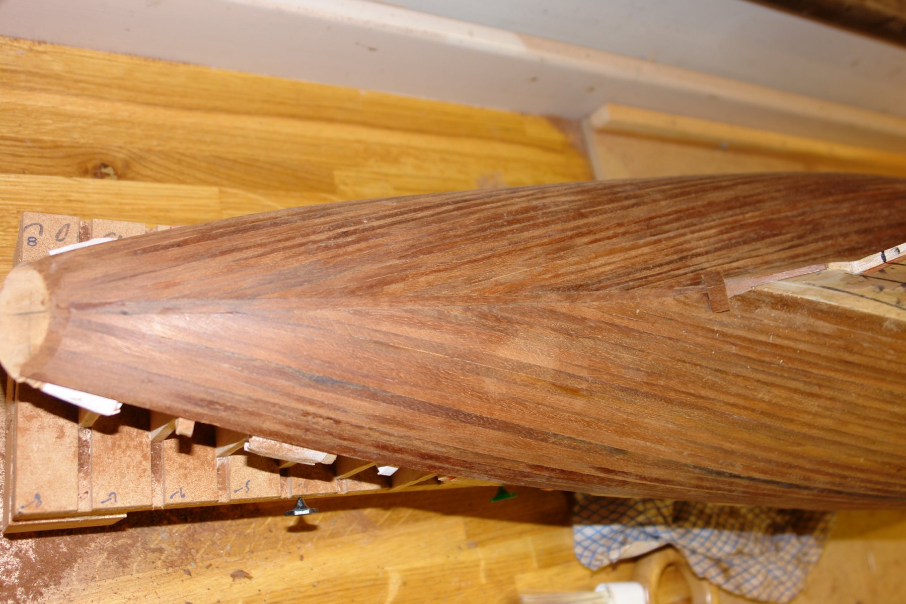
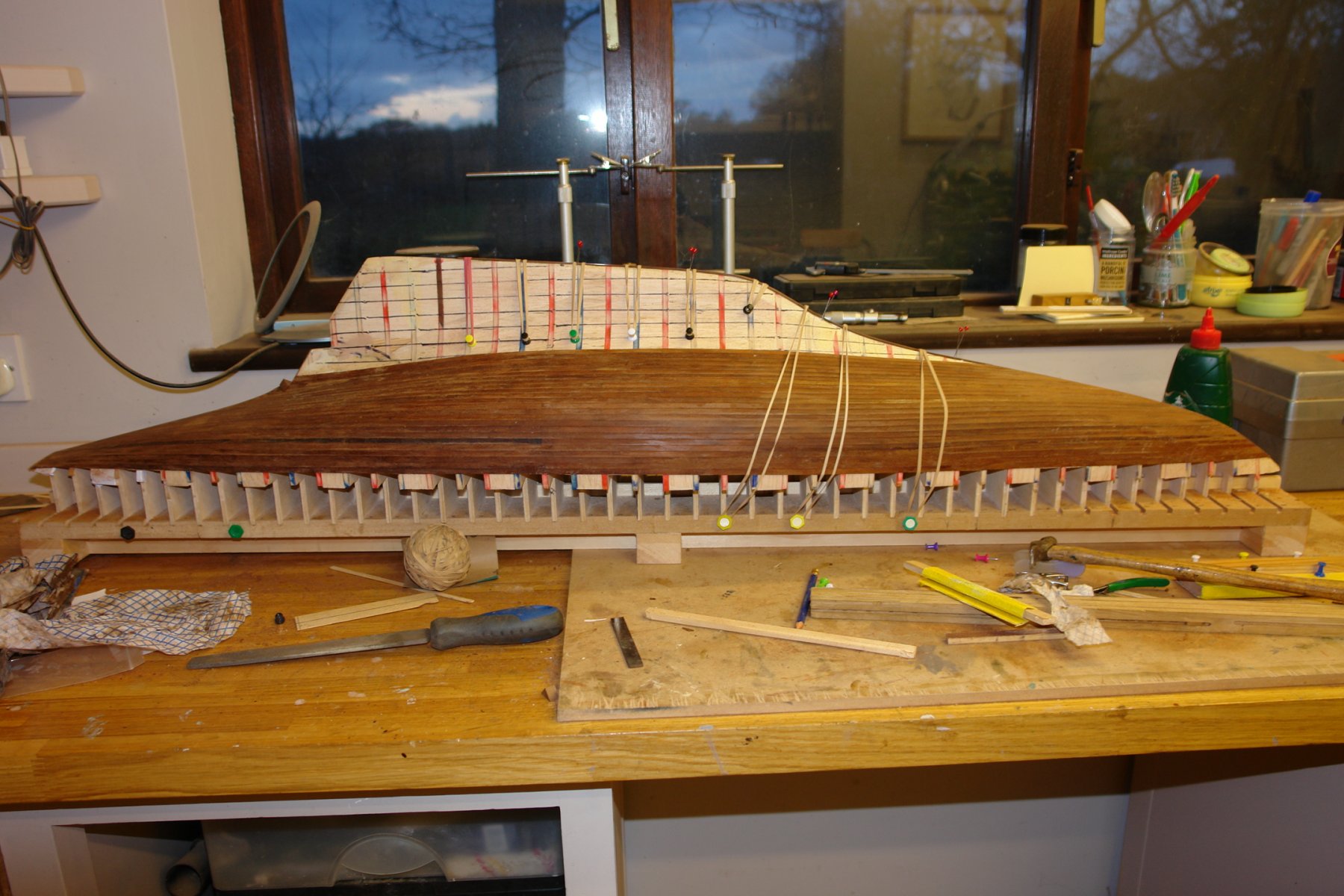
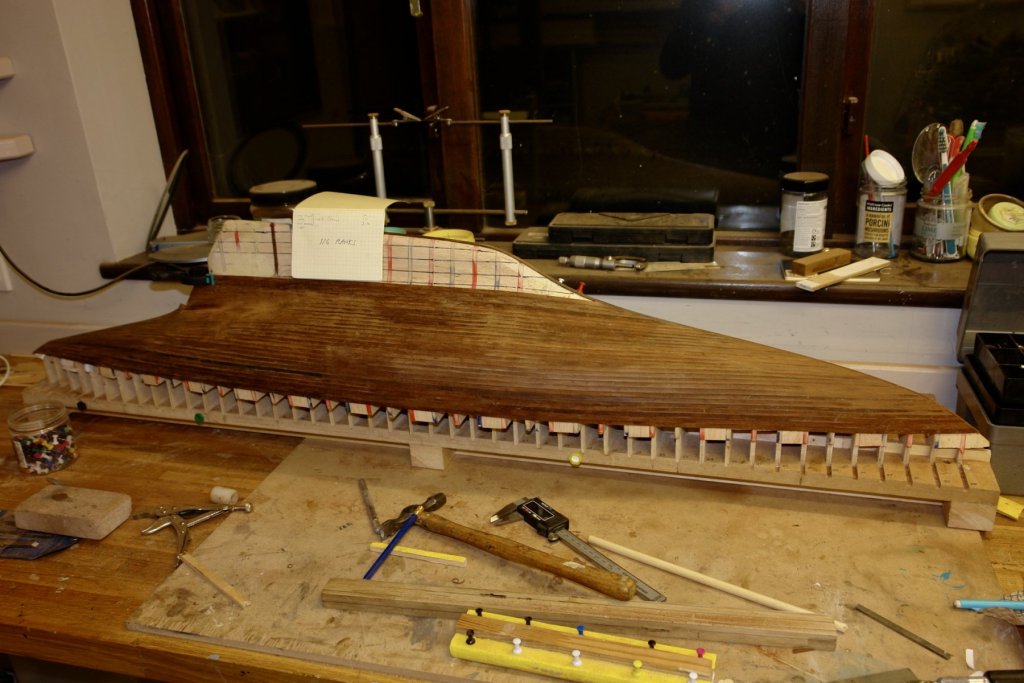
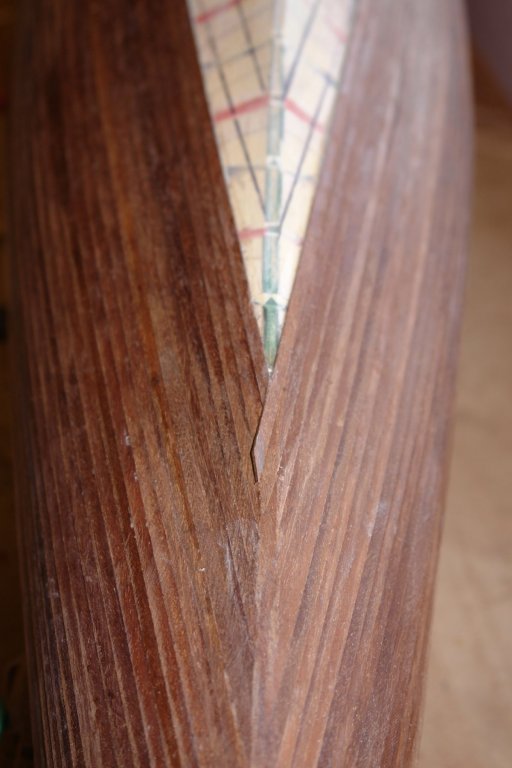
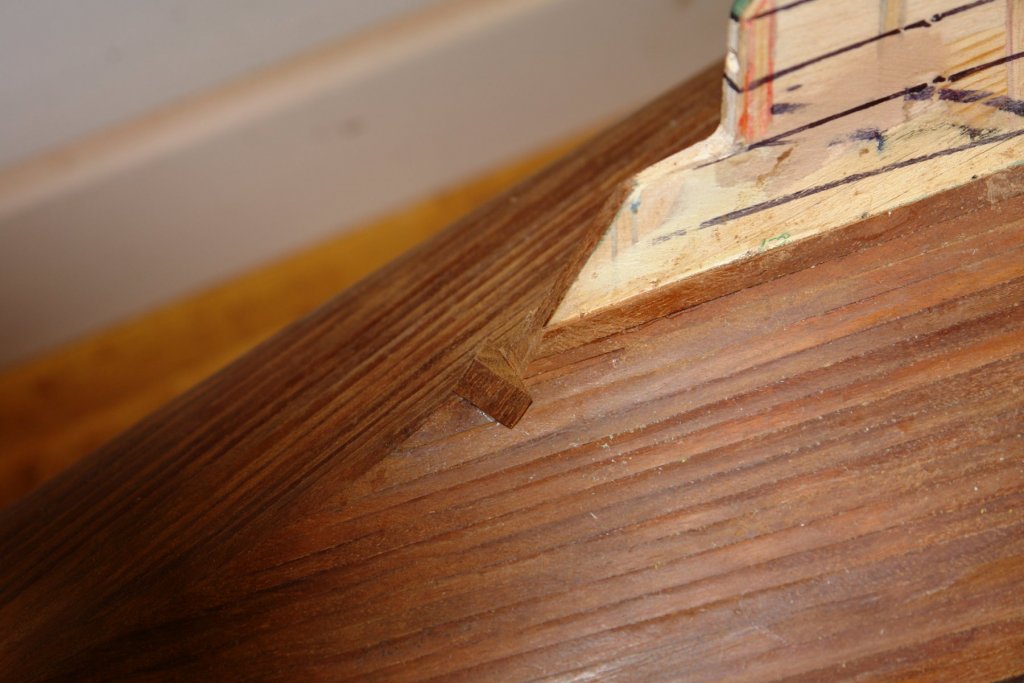
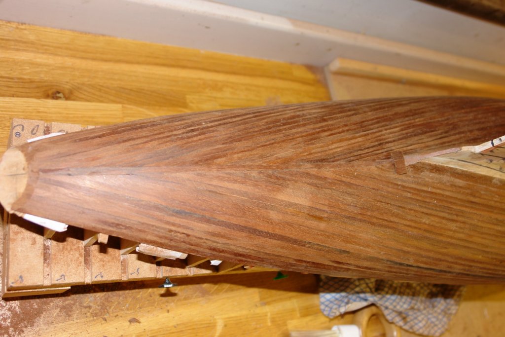
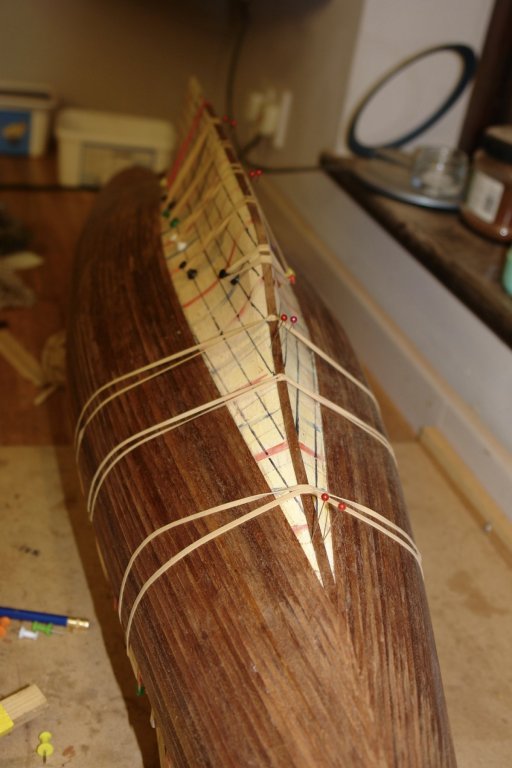
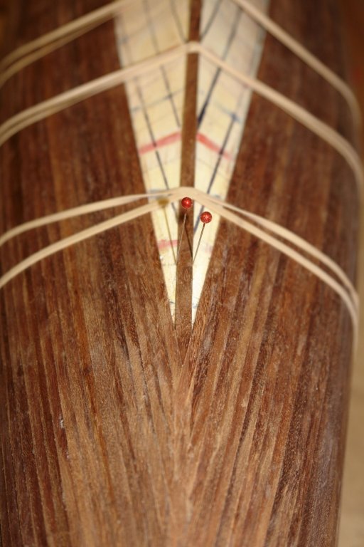
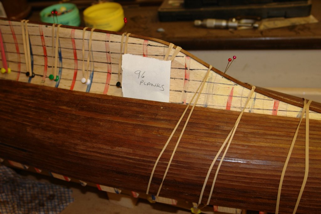
Planker's Progress 5 - Day 10. I got to the point on the underside of the bow where the planks were very flat where they intersected. I needed to change strategy so I introduced a "keel" plank with the intention that further planks would be butted against it. I also inserted a small block at the top of the rudder which will be sanded to give the hull in this area it'd final shape. The problem I was having with planking (as recorded in Planker's lament) was to the right of the inserted block. Here the curvature is acute and the planks were being distorted more than was good for them. I pressed on rather than rethinking and ended up cutting out a section 3 planks wide by 6 inches long and redoing it. I must remember that rework is slow - much better to do it right first time. In the next photo you can see that the extent to which taper planking has filled out midships relative to the bow and stern. As I proceed I will have to start sorting out the aft end of the keel where stealers will obviously be necessary. I finished day 10 with a planking count. So I make that 9.6 planks a day - good job I am not on piece work- obviously some way still to go.


-
Yes I looked at that and thought how much easier it would be if I could tongue and groove my planks. I'm not really up to it though on .055" thick planks.
-
Yes Eberhard - Thank you for the video, I found it very informative - what a lovely yacht.
-
Planker's Progress 5 - Day 9 I had a bit of a frustrating day today so I took it out on paper:- Planker’s Lament. I scratched my head and gave a sigh. The plank won’t go. It lies awry. Its tortured course. From stem to stern. Describes an arc of some concern. Concave, a twist and then convex. Its aim, I’m sure, is to perplex. I scratch my head again and sigh. And wonder where the time went by.
-
Jon An interesting little project which I will follow with interest. Seems to me that the new will be much more extensive than the old!
-
Dan It is always a good Sunday afternoon when one of your updates appears. Lovely work on the funnels.
- 238 replies
-
- 8
-
-
- leviathan
- troop ship
- (and 2 more)
-
Isn't it annoying when your fingers are just too big. Very nice work despite your finger problem.
- 714 replies
-
- 2
-
-
- lady nelson
- victory models
- (and 1 more)