HOLIDAY DONATION DRIVE - SUPPORT MSW - DO YOUR PART TO KEEP THIS GREAT FORUM GOING! (89 donations so far out of 49,000 members - C'mon guys!)
×


KeithAug
-
Posts
3,980 -
Joined
-
Last visited
Content Type
Profiles
Forums
Gallery
Events
Everything posted by KeithAug
-
 Dan - it actually looks pretty complex to me - maybe your concept of complexity is starting to get a bit warped. She is looking very crisp.
- 238 replies
-
- 7
-

-
- leviathan
- troop ship
- (and 2 more)
-
Modern yachts generally have compressed air horns - powered by a disposable air canister. I can confirm they are very loud - particularly when used to raise a weary watch crew on a night sail. Michael - the wheel looks like a fun little job!
-
yes Michael - I sometimes get strange ideas in my head - like "filler is cheating". Silly really as its going to be buried under planks. John / Pat - thank you.
-
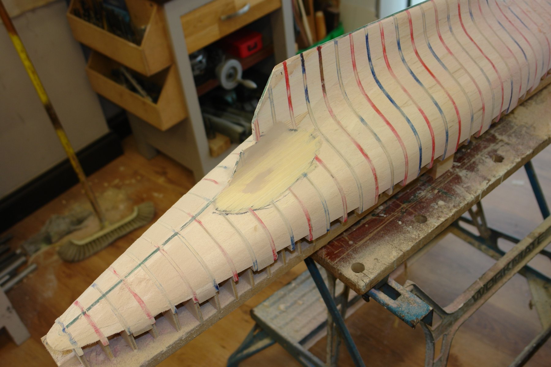
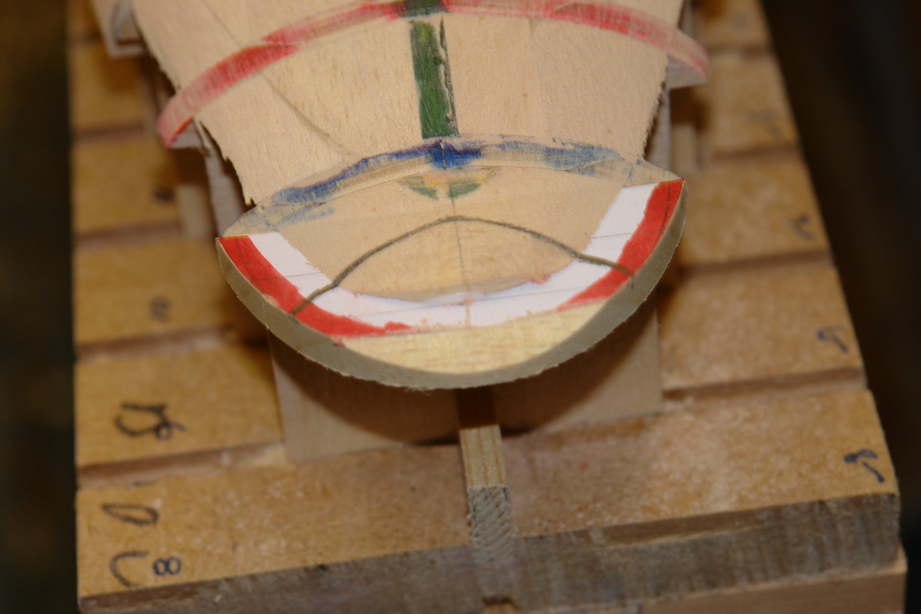
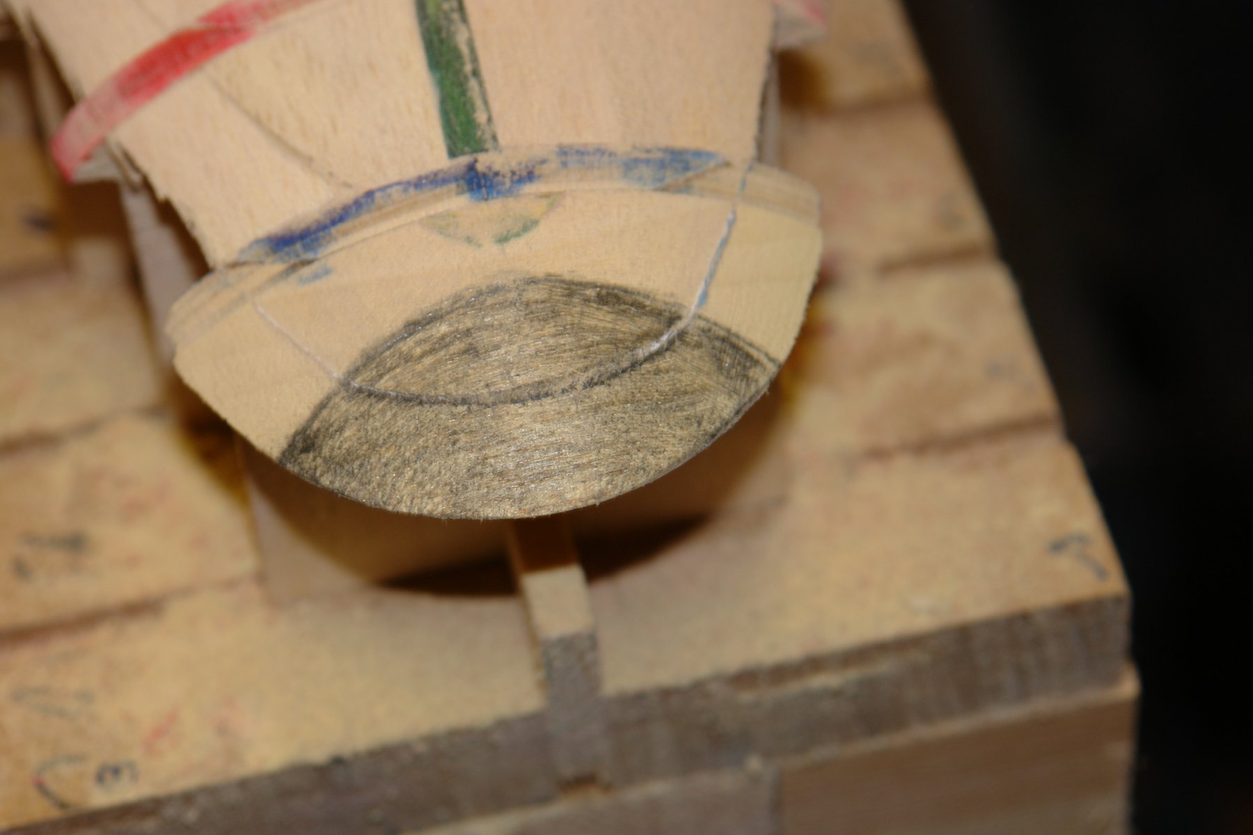
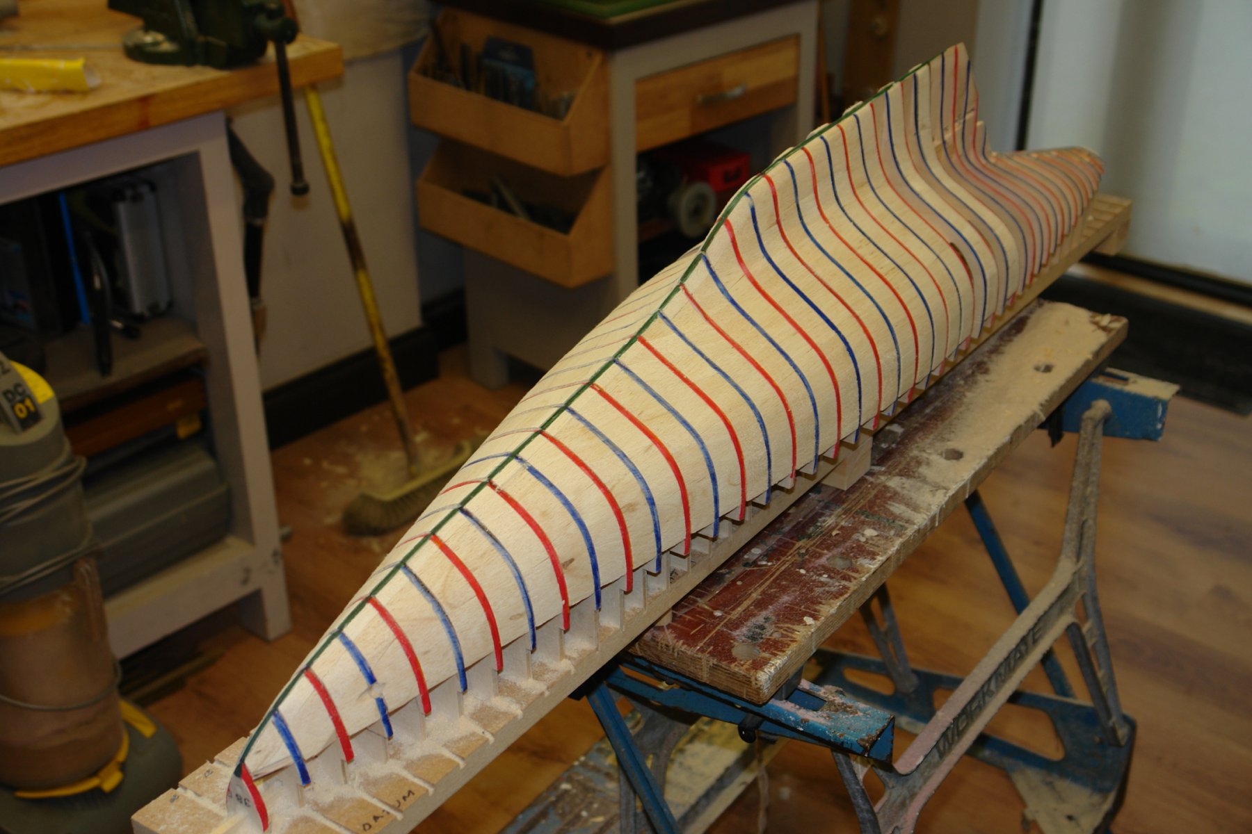
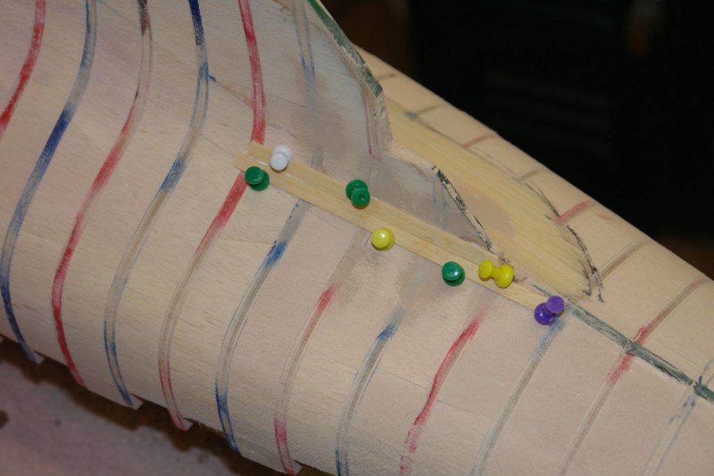
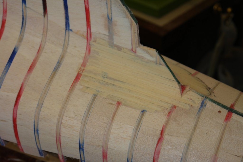
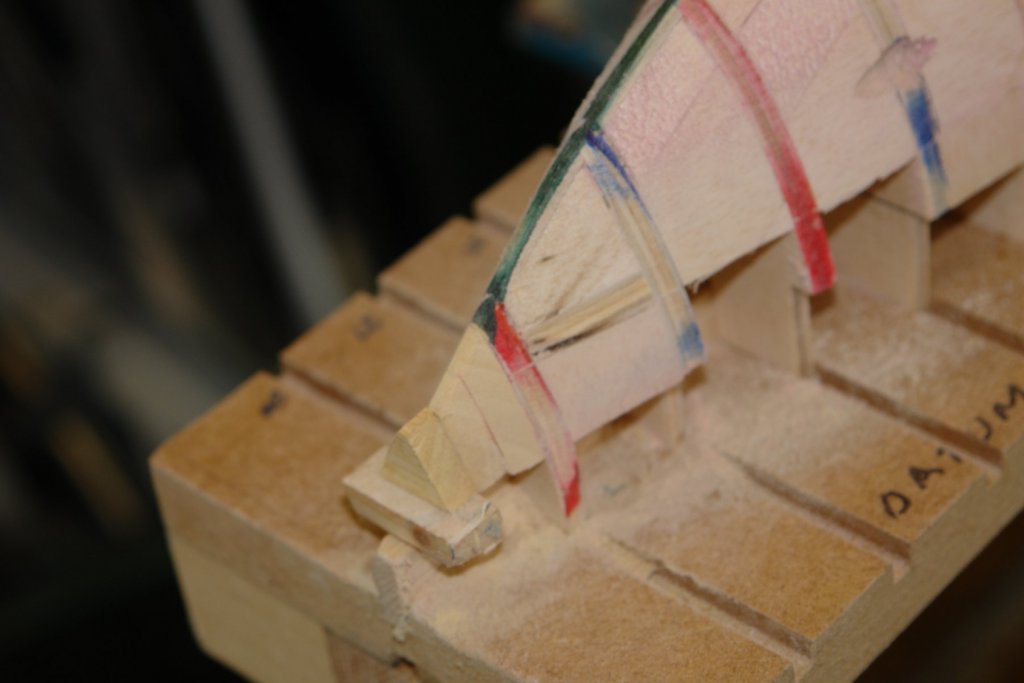
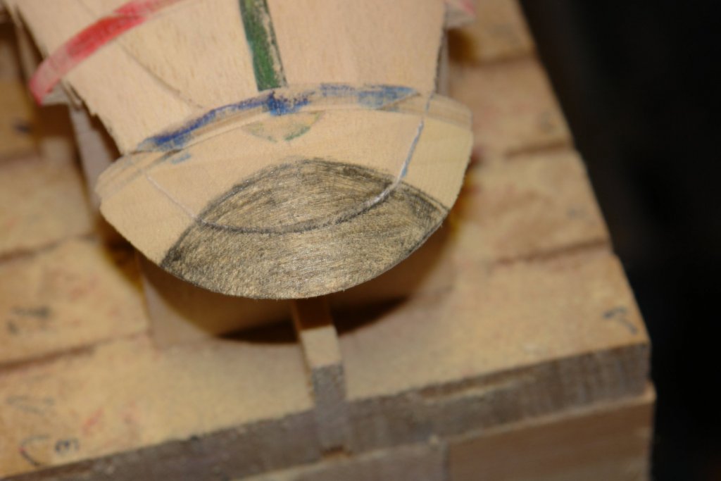
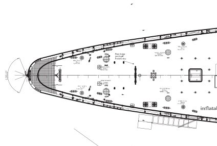
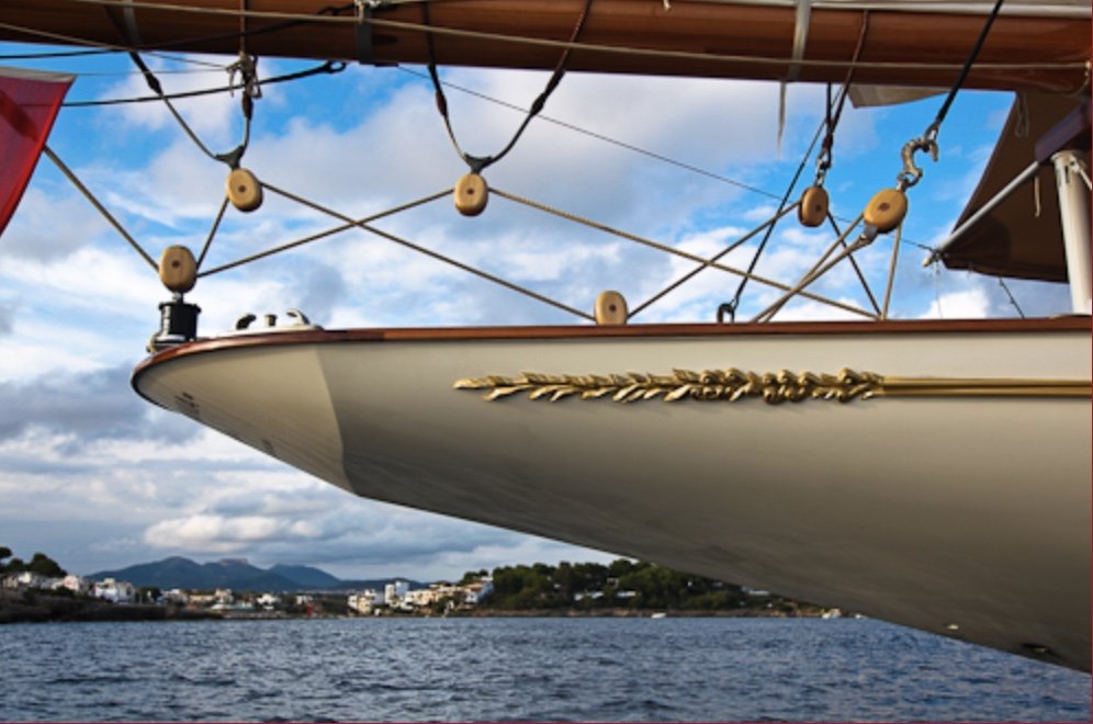
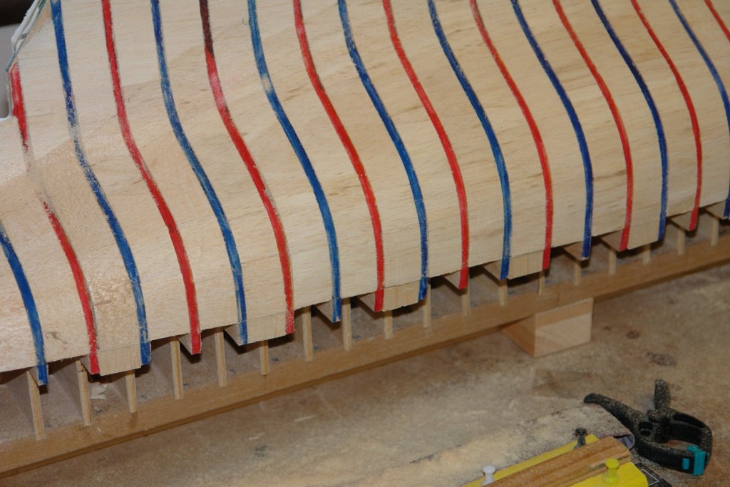
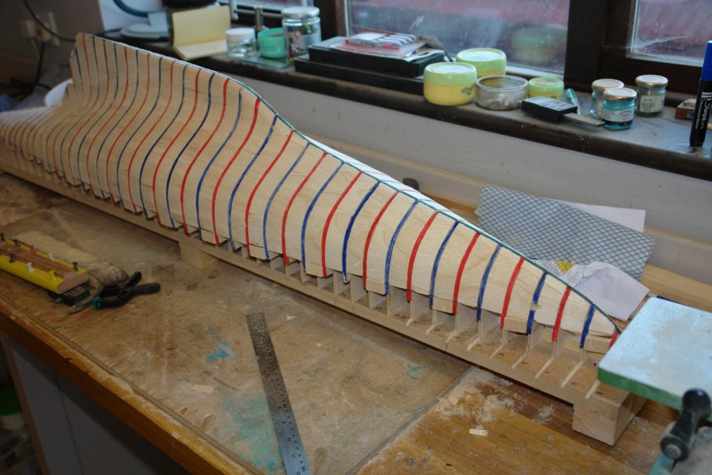
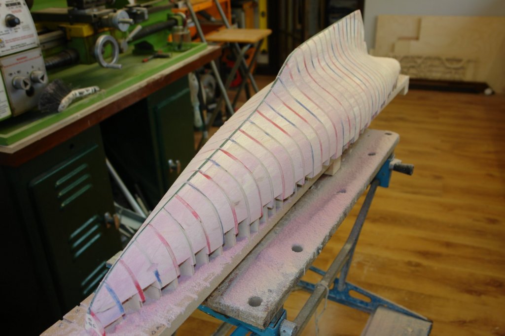
Yes Michael - very much a racer. Druxey / John - thank you. I am now sorting out the hull before I commence planking. As predicted by Eberhard, the infill allowed me to find problems before they manifested themselves as hull irregularities after planking. The issue with the original lines drawing was that in areas of quickly changing curvature insufficient points were available to accurately define the hull shape. Having sanded the balsa infill back to the frames I spent some time running the palms of my hands over the hull to identify discontinuities. All was well with the exception of keel to hull intersection at the rear of the keel. Here there was a definite hollow. Using a straight edge I deduced the the dip covered an area of 6"x3" and was a little over .040" deep at its lowest point. The dip was present on both sides of the keel indicating that the frames were slightly off. I decided to plank over the hollow with .050" x .250" obechi planks and then sand back to remove it. I did the port side first. In the following photo the port side has been done and I have started planking the starboard And here the starboard side is done. You can see that much of the planking has been sanded away. I then spent a little time building up the bow in front of the foremost frame. Once this are was completed I moved on to sort out the transom. The transom on these classic yachts is quite an interesting area. When viewed from directly above or below the stern follows a smooth curve. Whereas the transom itself is curved in one direction while being flat in the other. When I first did a transom I was a bit perplexed as to how the various curves interacted and I only sorted it out by by trial and error. In the next photo I have added the above deck former. This will be removed later and I have inserted a piece of paper to act as separation surface. The line of the transom has been marked on and I have started sanding the above deck former. Some time later the transom form has been achieved. As can be seen the shape turns out to be an "eye" shape which is almost symmetrical about the major and minor axes.


-
Kortes New planking looks good - how did you remove the old planking?
- 306 replies
-
- 2
-
-
- schooner
- la jacinthe
- (and 1 more)
-
ancre La Salamandre by tadheus - 1:24
KeithAug replied to tadheus's topic in - Build logs for subjects built 1751 - 1800
Always a joy to visit your build Pawel -
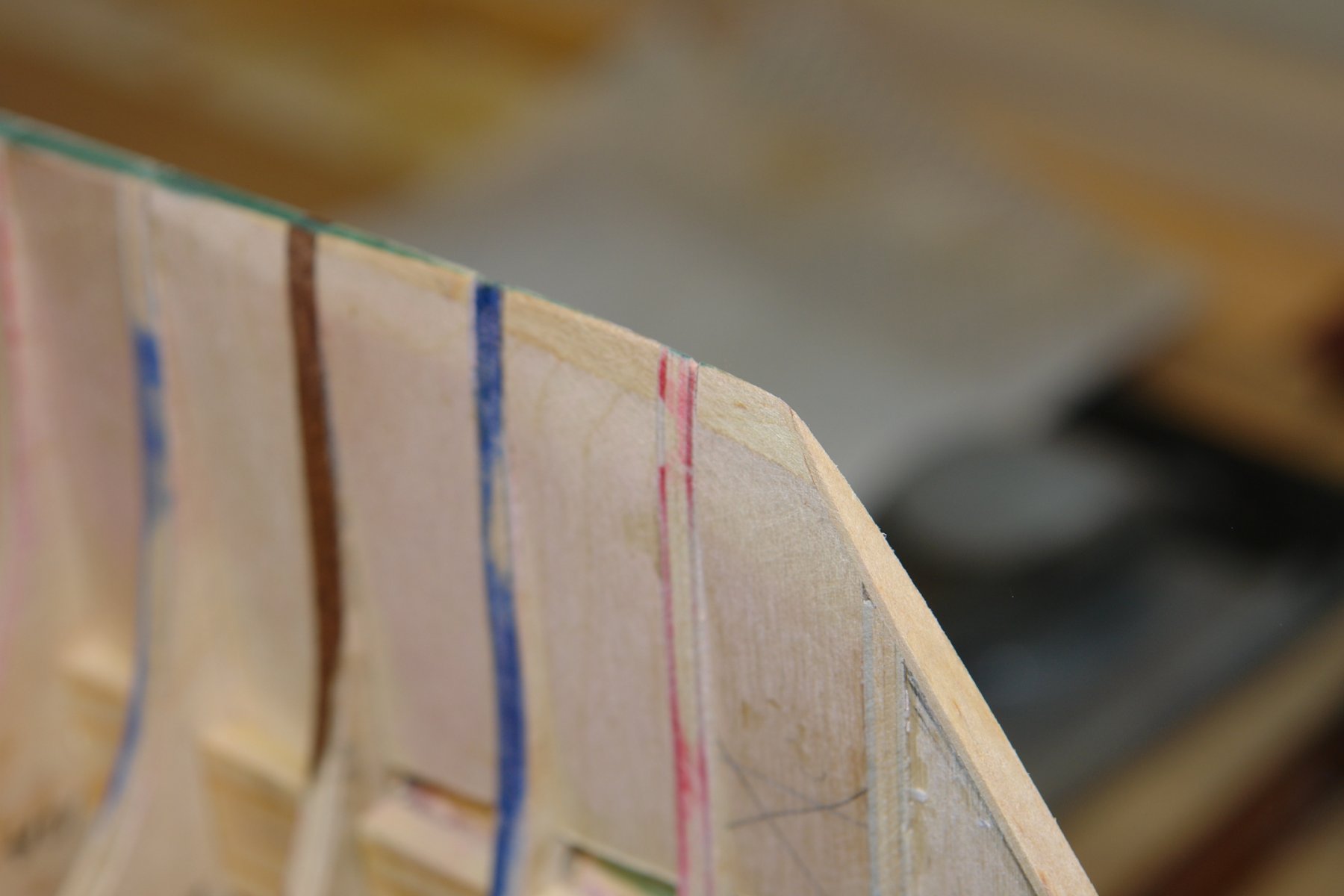
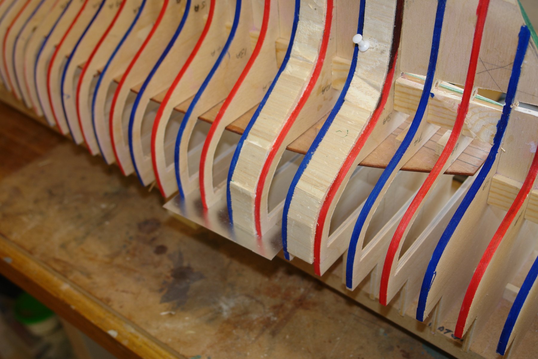
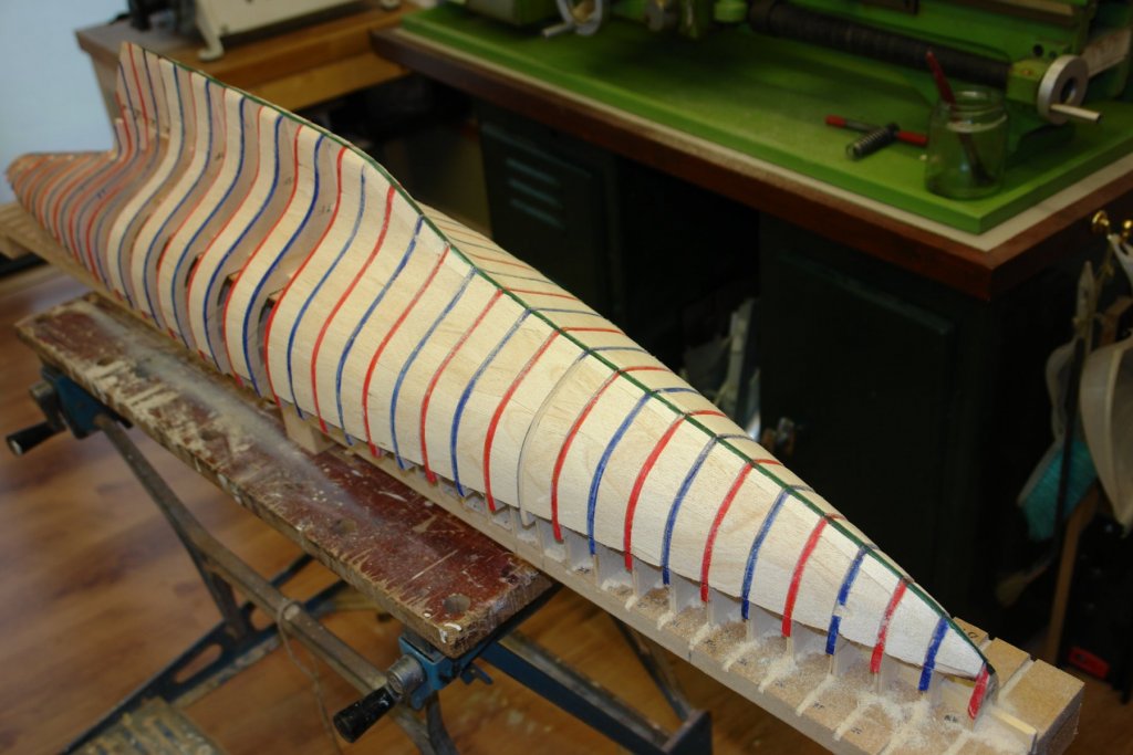
A little more infill work and the then I completed the rough sanding. Still thinking about the bulwarks I added infill blocks at every 3rd frame. I though this would aid securing the bulwark planks while glueing. Obviously they have to be removed once the bulwark is finished and I though one in three a good compromise rather than filling every space. Then it was on with final sanding - this time taking the surface down to the frames with light sanding on the frame edges. The pinky purple sanding dust was a bonus.

-
Michael - scrap box's wouldn't be so useful if it wasn't for experiments.
-
Hello Sorjs. I built this model nearly 30 years ago and I still have the finished model. It is interesting to see how Billings have value engineered the kit over the years. When I built the kit nearly all the hull was planked - none of the large flat plywood panel sections you have had to deal with. As a consequence of the planking solution the hull profile was much less angular than yours. It is a pity that in the pursuit of profits manufacturers are inclined to cut corners on even the less expensive materials. I cant believe that the cost of a hundred of so obechi planks rather than ply would have made the kit uneconomic. I hope you health is improving.
-
Excellent Patrick - so is it back to boats now you have finished your intergalactic space cruiser?
-
Ah yes good point Andy - always pass the port red wine to your left.
-
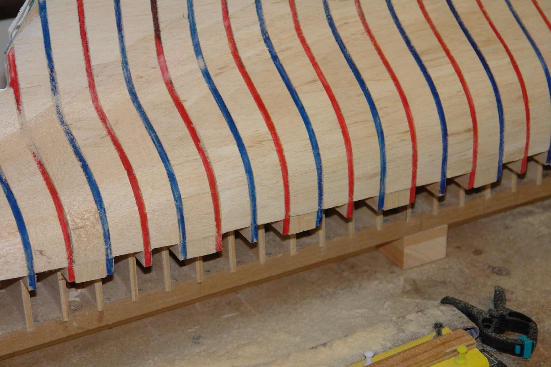
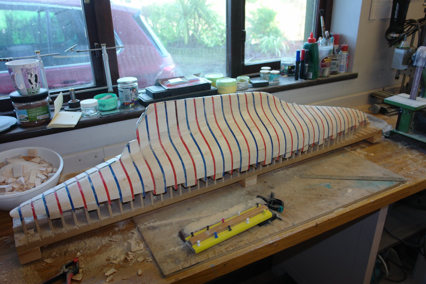
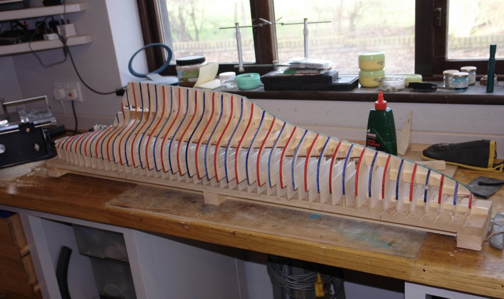
I finished fairing the frames - the bottom of the keel turns out to be unbelievably fine - i think I will correct it to have a small radius curve as part of the planking process. As I decided previously I made a start on infilling between the frames. But first I re-coloured the frames in preparation for further sanding later on. I infilled with medium hardness balsa in a range of thicknesses - 1/4" 3/8" and 1/2". I quite enjoy the process although it is a bit time consuming. I am sanding the balsa to be flush of the frames as I go along. I will finish sand once the infill is complete. \ The sanding dust is getting everywhere.


-
Excellent work Michael - now i need one at scale 1:36 for Germania's launch, how about it?
-
Wefalck Michael gave away your christian name - it is less impersonal than Wefalck. Do you mind if i use it?
-
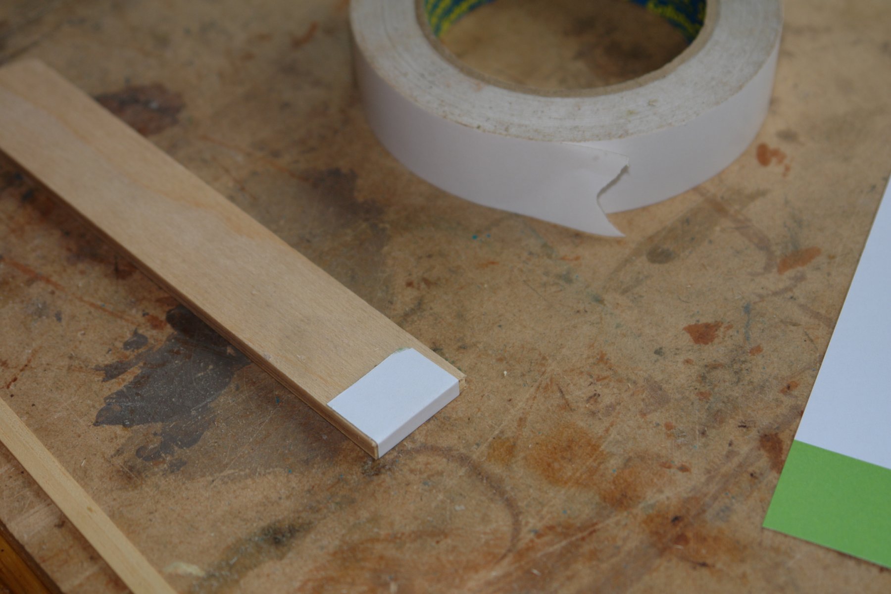
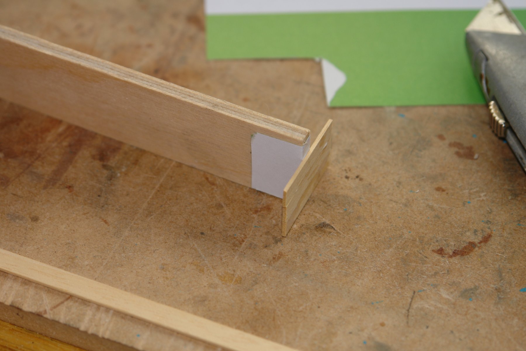
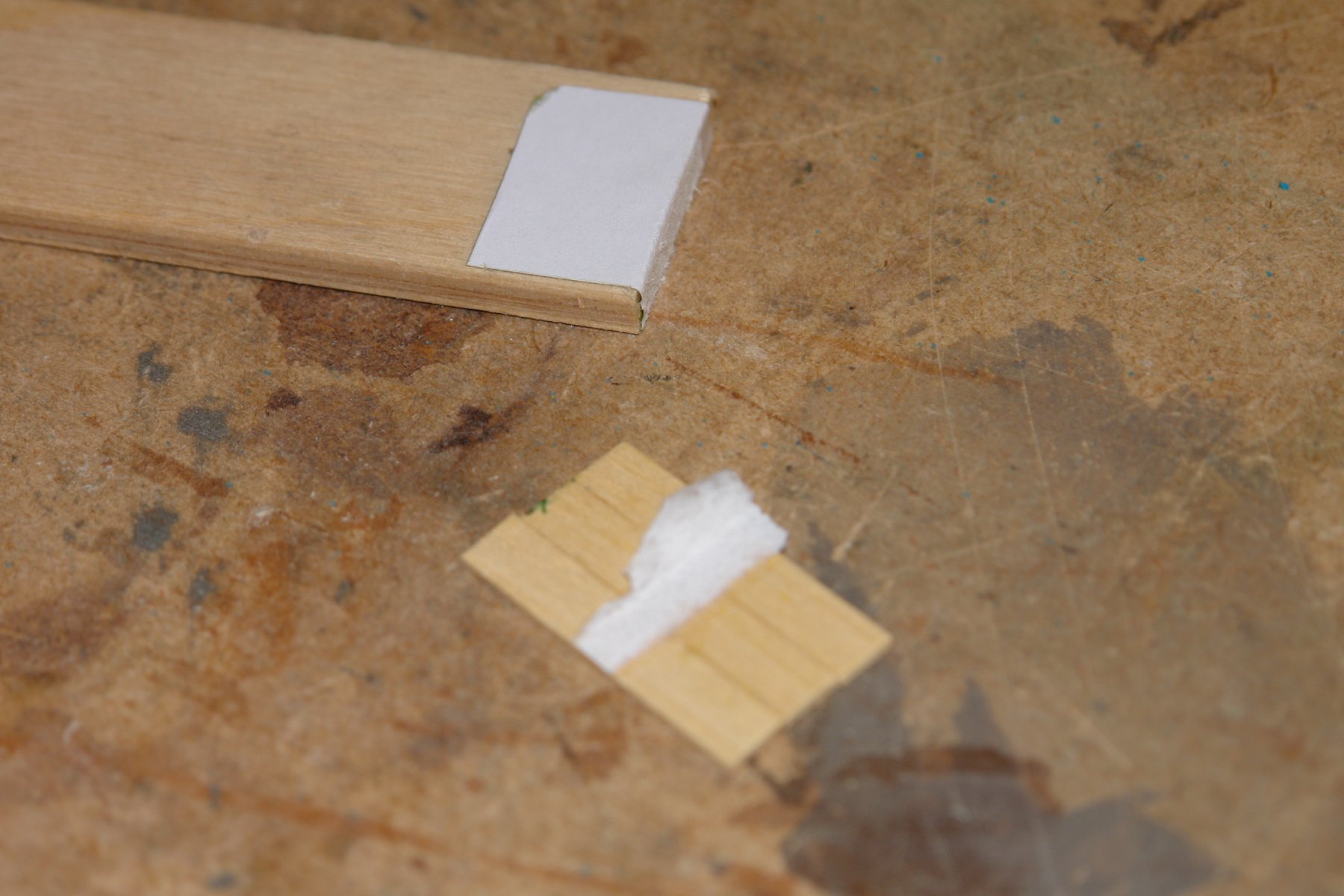
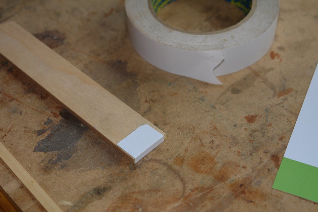
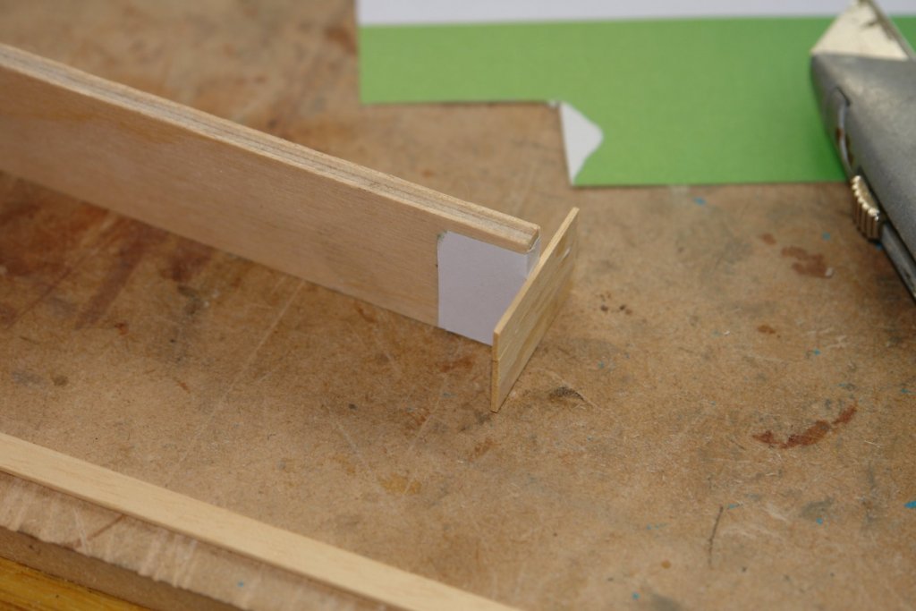
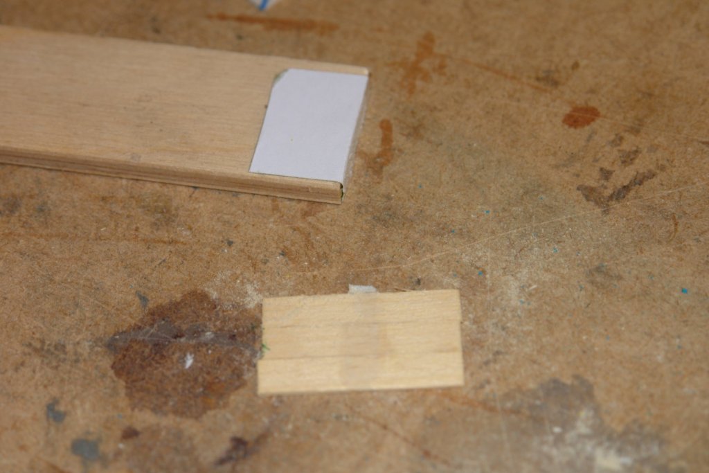
All this dialogue on the subject of bulwarks prompted my reflection of the earlier suggestion from Pat (Banyan) re preventing the bulwarks from attaching to the above deck frames (these will act as temporary formers for the bulwarks). My thought process went along the lines of "having my cake and eating it". In practice I want to be able to glue the bulwark planks to the frames while I build the bulwark, but it don't want the planks glued to the frames once the bulwark is complete. With this in mind I decided to try a solution whereby the bonding of the planks to the bulwark was strong enough to provide the necessary support during assembly but weak enough to be easily removed once the assembly was complete. Hence the following experiment:- I took a piece of ply the same thickness as the frames and stuck a piece of paper over the end using double sided tape. I then glued the simulated planks to the paper covered edge with PVA and allowed it to dry. Once dry I pulled the ply away from the planks. The force to do this was small and the paper split as I expected leaving one surface on the edge of the ply and one surface on the planks. I then did a light sanding - just enough to satisfy myself the the paper on the planks would remove easily. I think I am going to try this on the build.

-
Im afraid that I too prefer wood or metal - and anyway I do not think I am in the "Doris" skill class. I'm going to have a go with mahogany first and default to other options if I can't make it work.
-
Yes I agree. My thought was turn up a bar to the OD of the gear with a spigot the diameter of the gear bore - then glue the gear on with superglue, turn the recess and then heat to break the superglue bond. I thought however that Valeriy might have a better plan.