KeithAug
-
Posts
3,986 -
Joined
-
Last visited
Content Type
Profiles
Forums
Gallery
Events
Everything posted by KeithAug
-
 Michael - not sure about the tea idea. Have you thought about Macallan 25 year malt. Much the same colour as tea but with greater preservative qualities. A further advantage is everything looks fuzzy after a while so the line fuzz wouldn't stand out.
- 749 replies
-
- 4
-

-
- albertic
- ocean liner
- (and 2 more)
-
Roger / John Its probably safe to say that while the wood is part of my plan for completion of the launch it isn't actually on the main route. Julie, thank you very much for looking in and for your kind comments.
-
I was wondering what was happening - good to see this again.
-
Oh goody, more entertainment. I have been missing this.
- 749 replies
-
- 6
-
-
- albertic
- ocean liner
- (and 2 more)
-
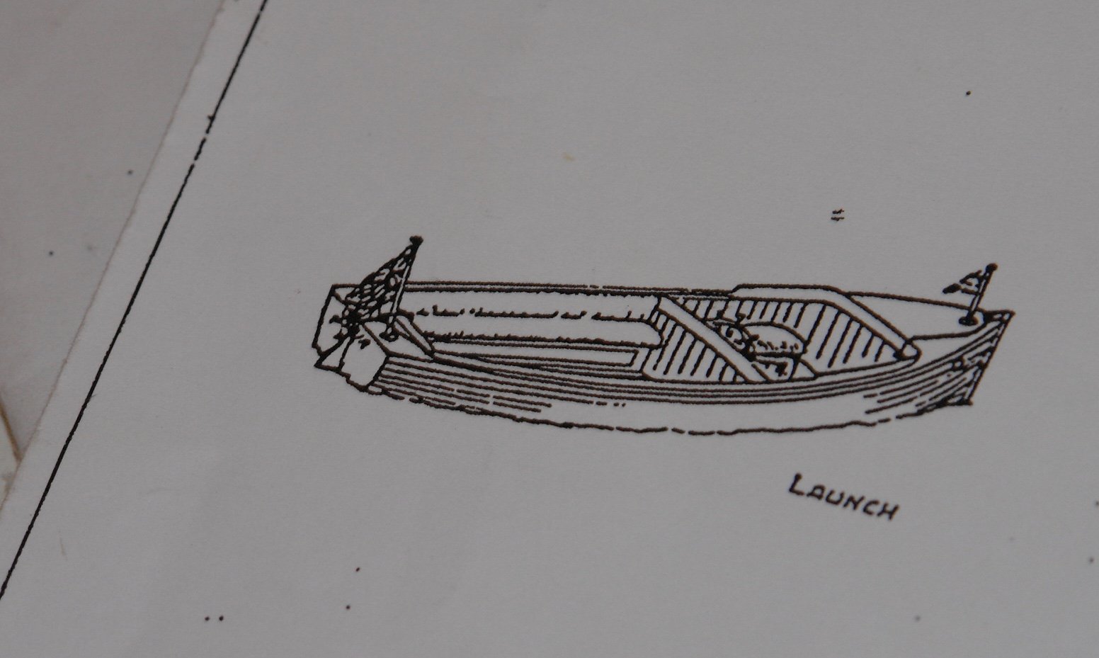
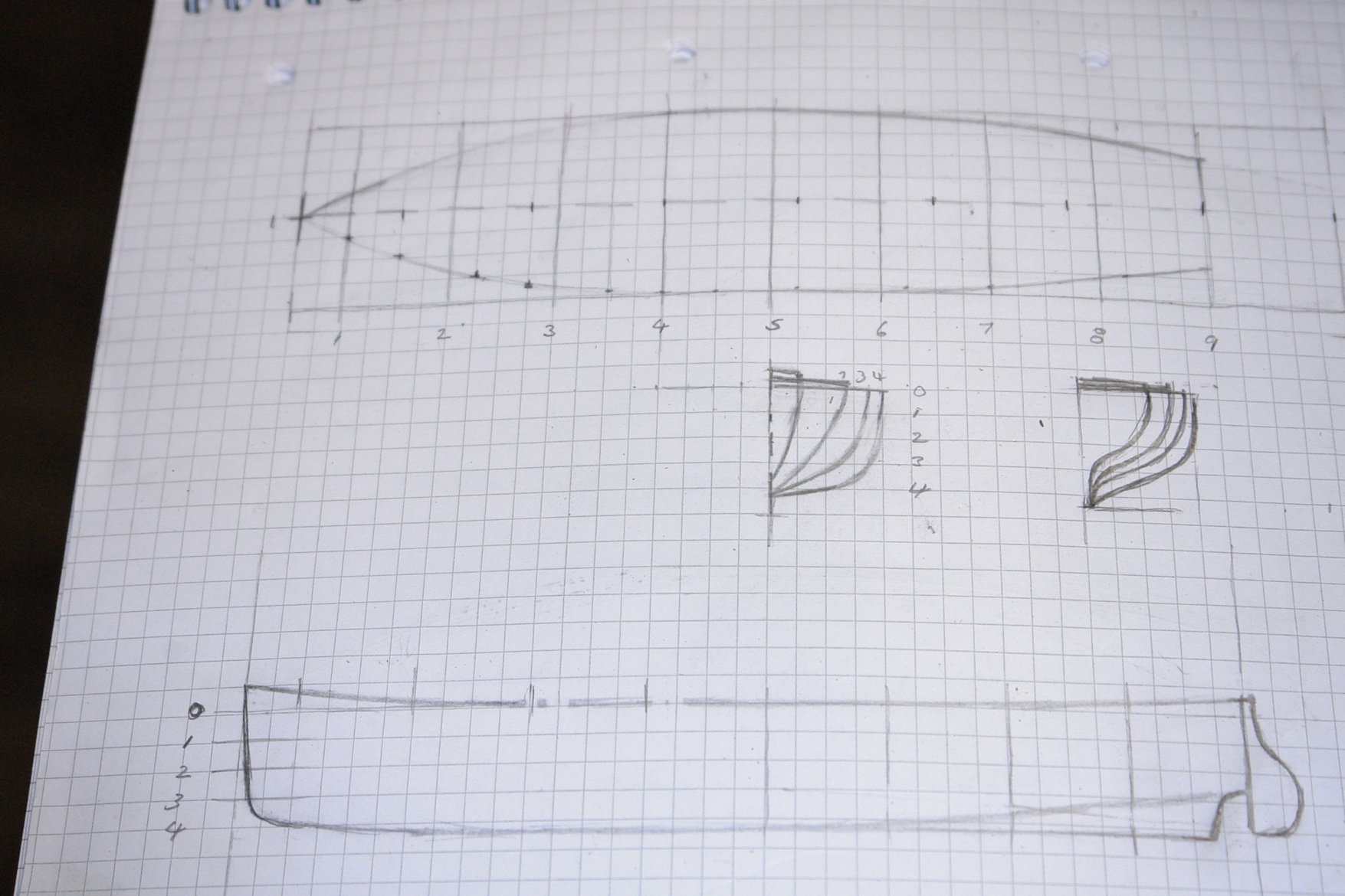
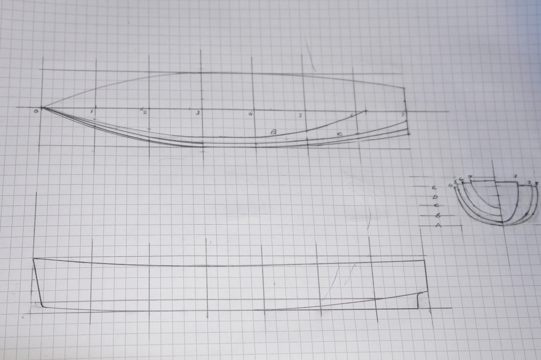
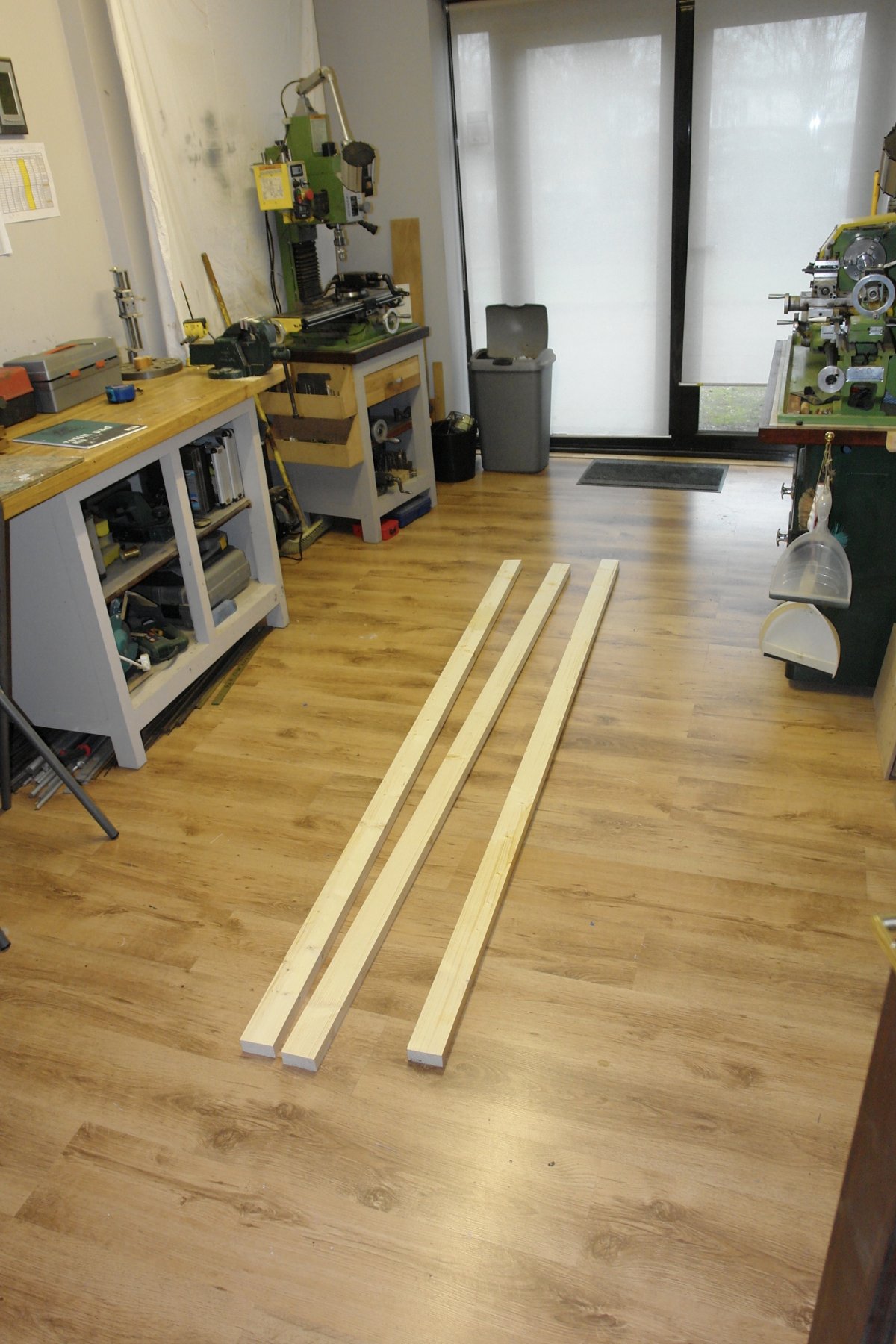
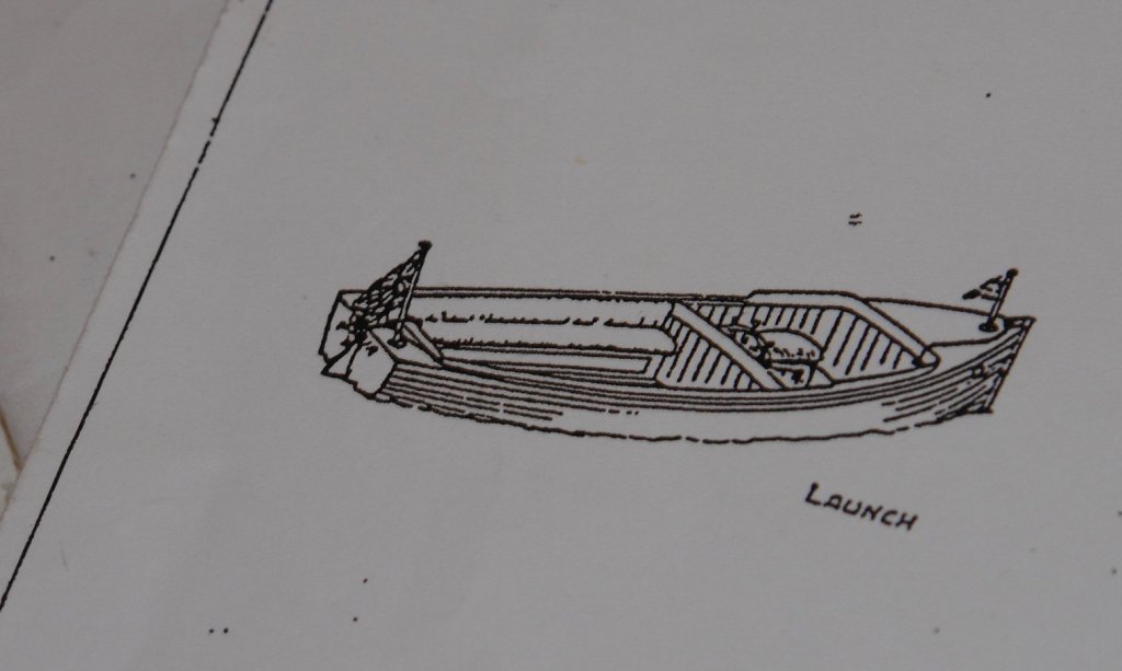
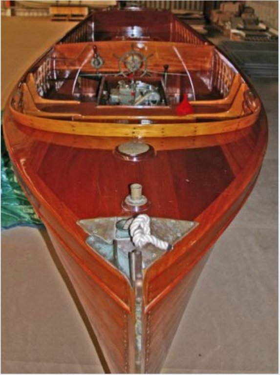
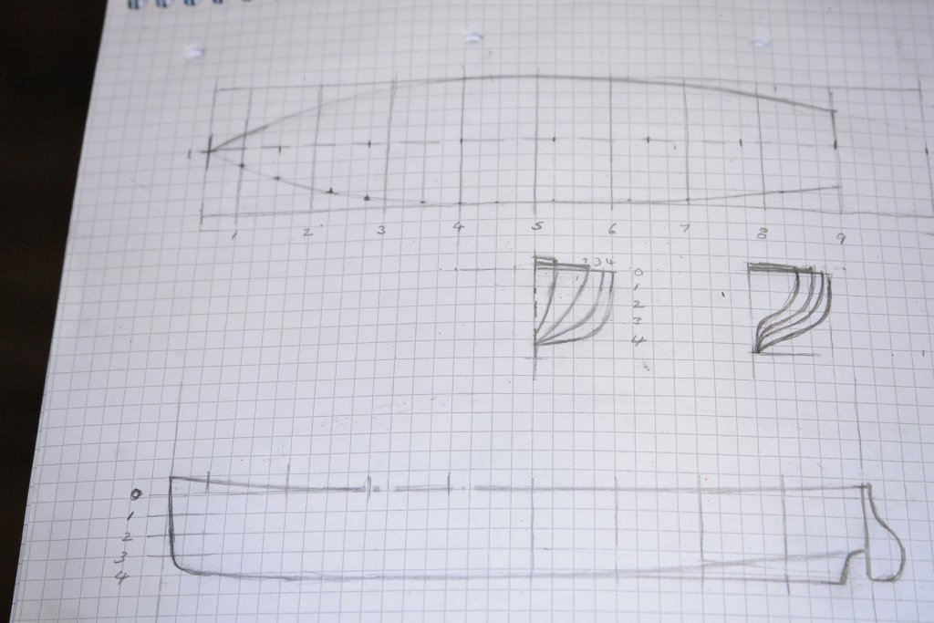
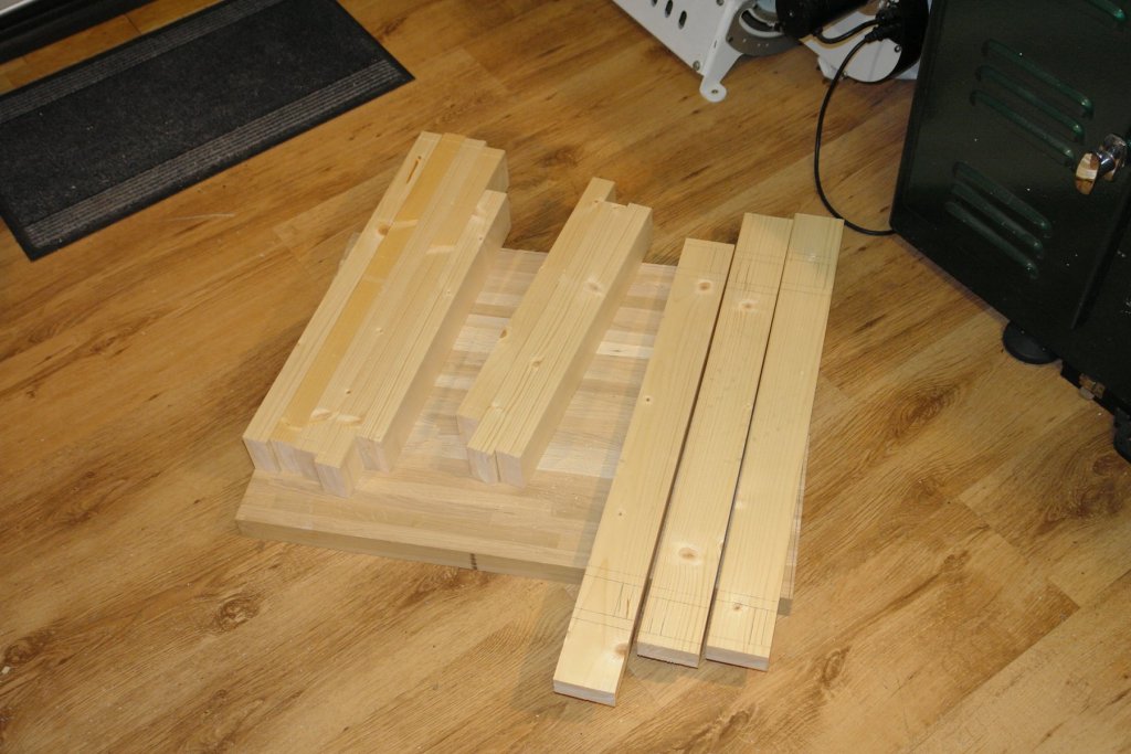
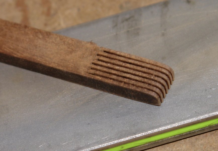
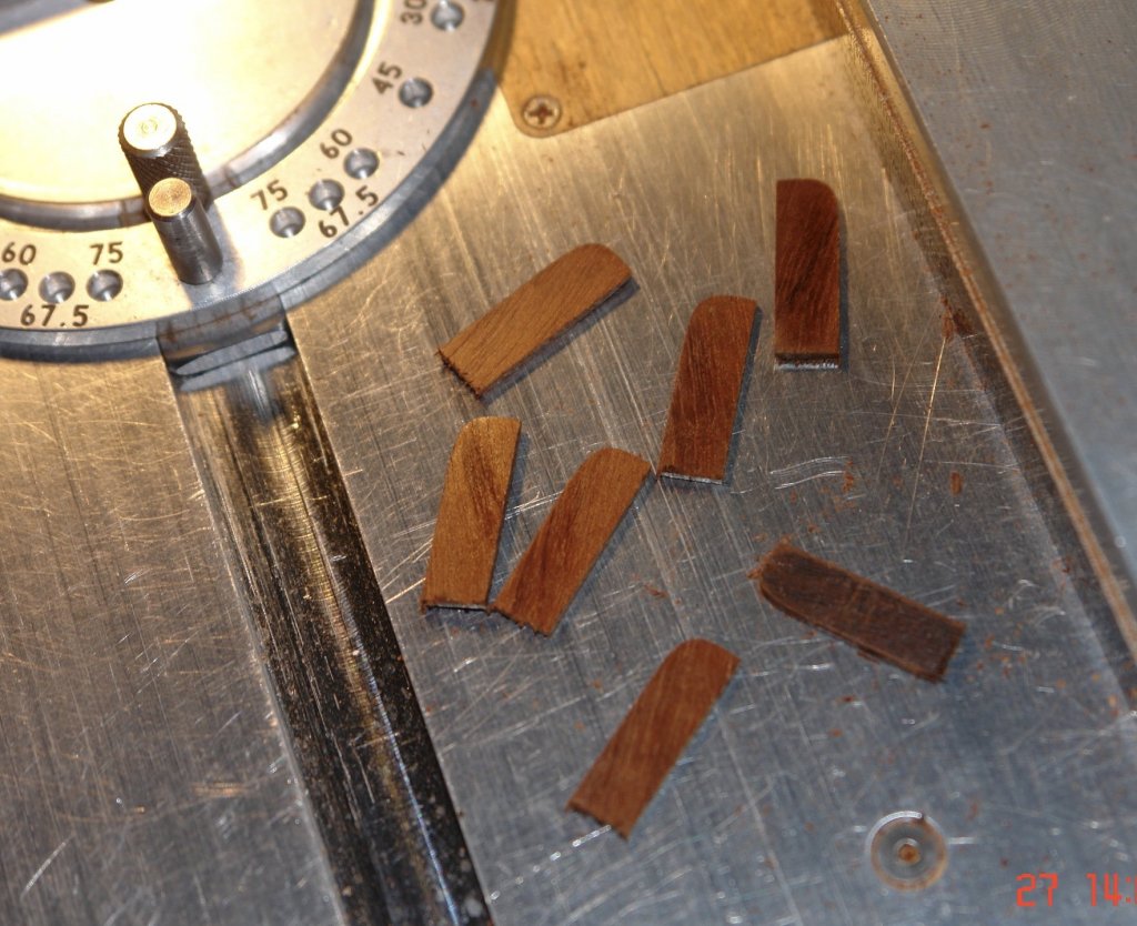
I tend to agree Michael - perhaps I need a replacement for my good camera. Herask - thank you - I will do a better job on photos once complete. So whats left to do - better make a list. I could rig a few missing haliards - for bosuns chairs, spinnaker and bloomer etc. I'm in two minds as to whether I am going to add these lines as they don't add anything and start to clutter the already busy mast profile. I have to add the rudder but this is a 5 minute job - not done at the moment as it binds on the temporary construction stand. The big jobs to complete are:- 1. Making the launch. 2. Making the stand. 3. Making the display cabinet. On the small jobs list is making the flags and flag staffs (always the last job). So to the launch which is going to be in some part a work of fiction. The sum total of the information I have to go on is as follows:- From the plans:- And from the web:- The first job was to do a rough sketch of the hull profile - followed by a more draughtsman like rendition. The launch is 7 inches long and the sections were iterated a number of times, plotting the vertical and horizontal section repeatedly until the profiles coincided. I then started cutting wood:-


-
Hello Mark I use Beadalon multi strand stainless steel beading wire. You can see the effect in the later posts of my Altair build - link below. Rather than using crimps I use small bore tubing with a spot of CA glue.
-
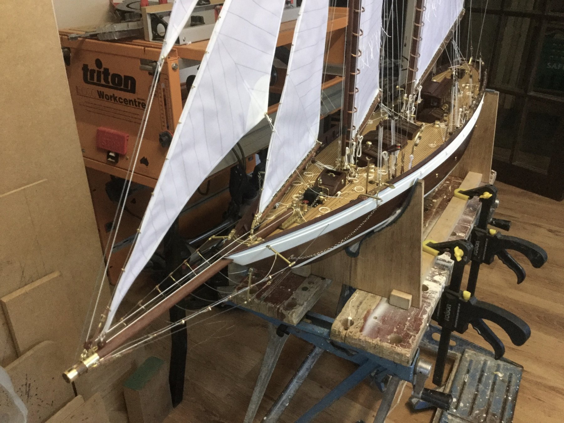
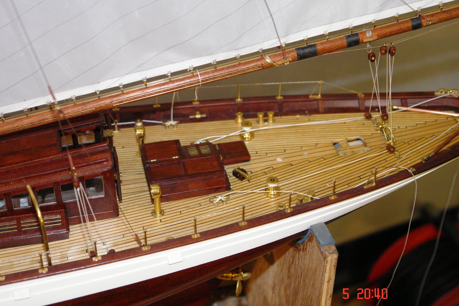
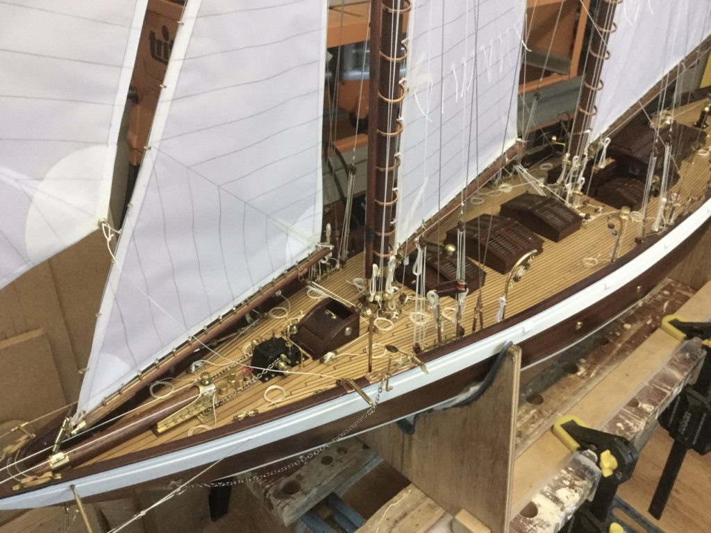
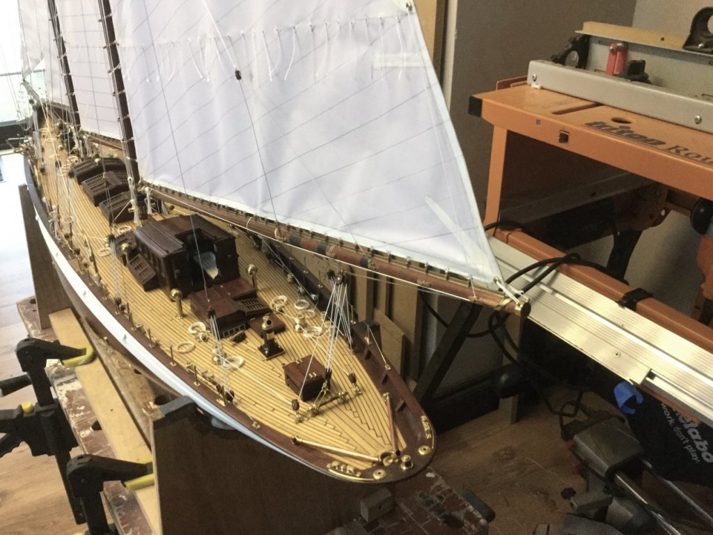
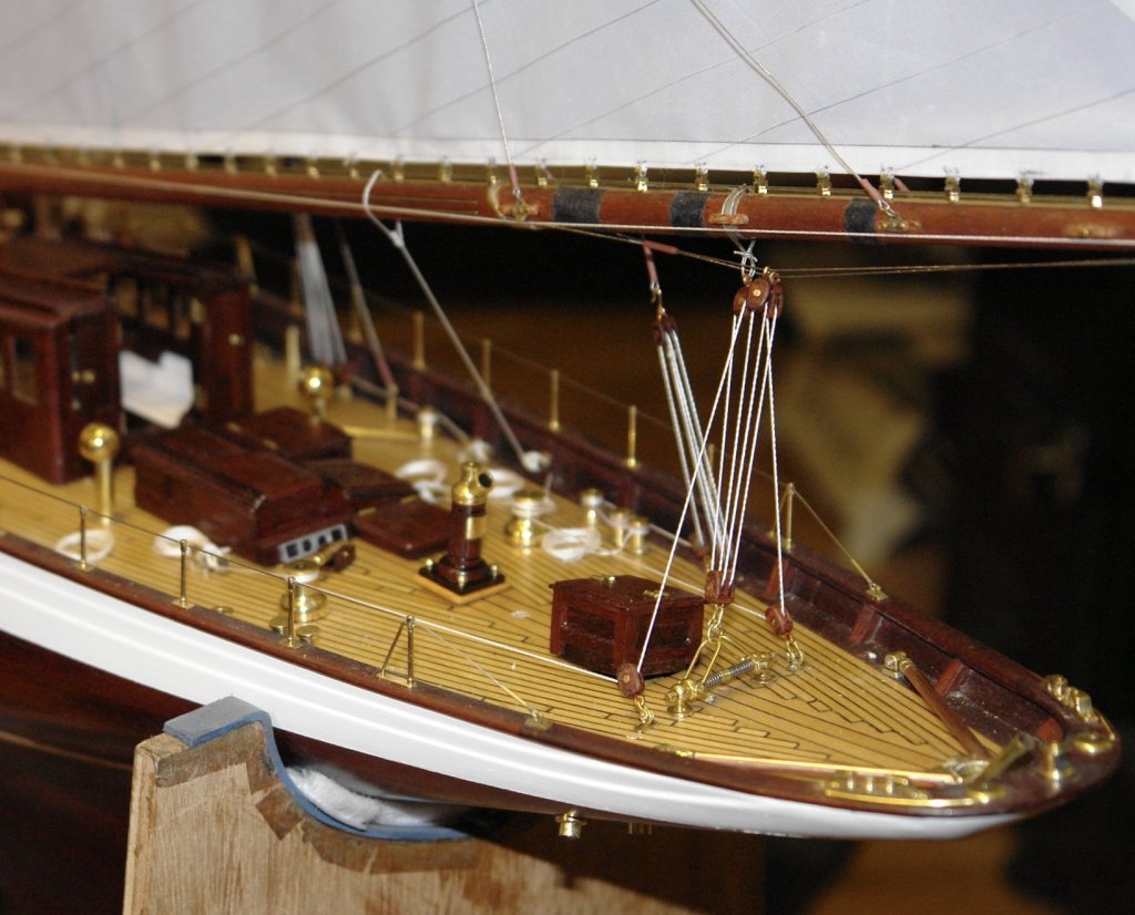
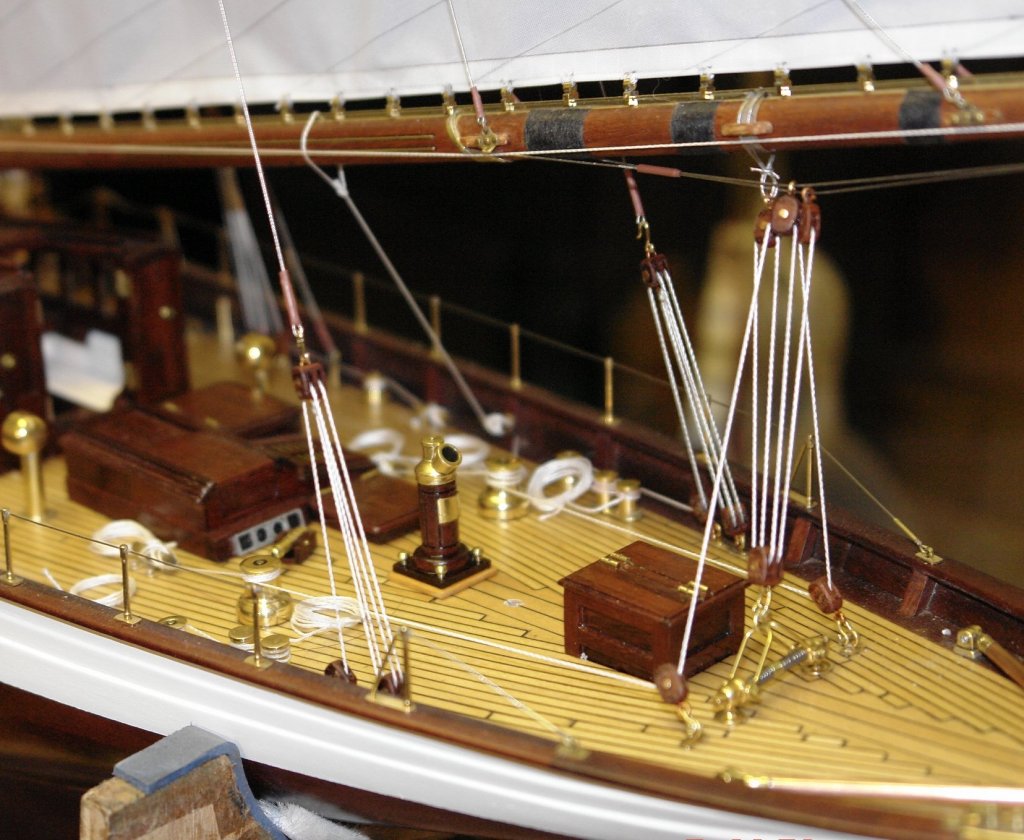
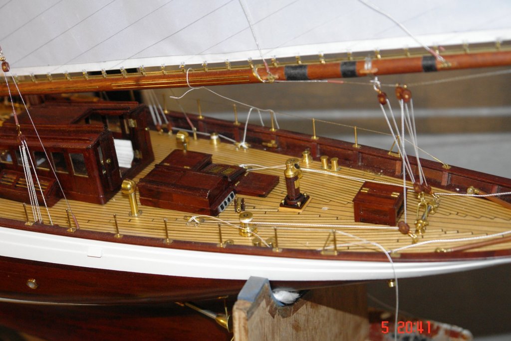
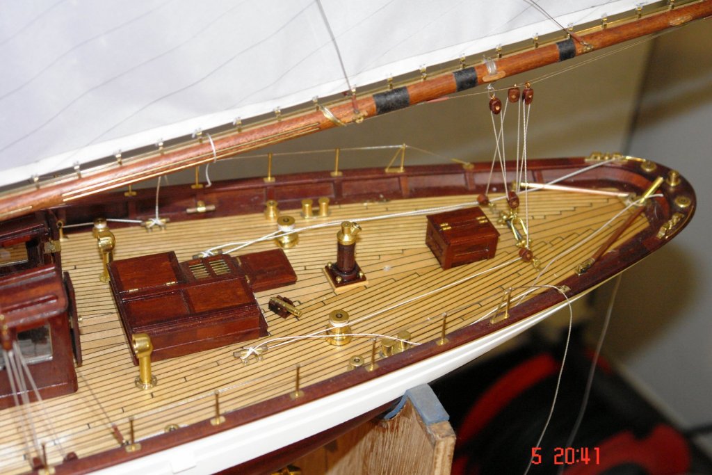
Michael, I’m not sure I want to hit it with a bottle, It is a bit delicate. Better just drink the champagne instead. I have just taken a few deck shots with the iPad camera. It is much better at keeping both the foreground and background in focus than my proper camera.


- 882 replies
-
- 10
-
-
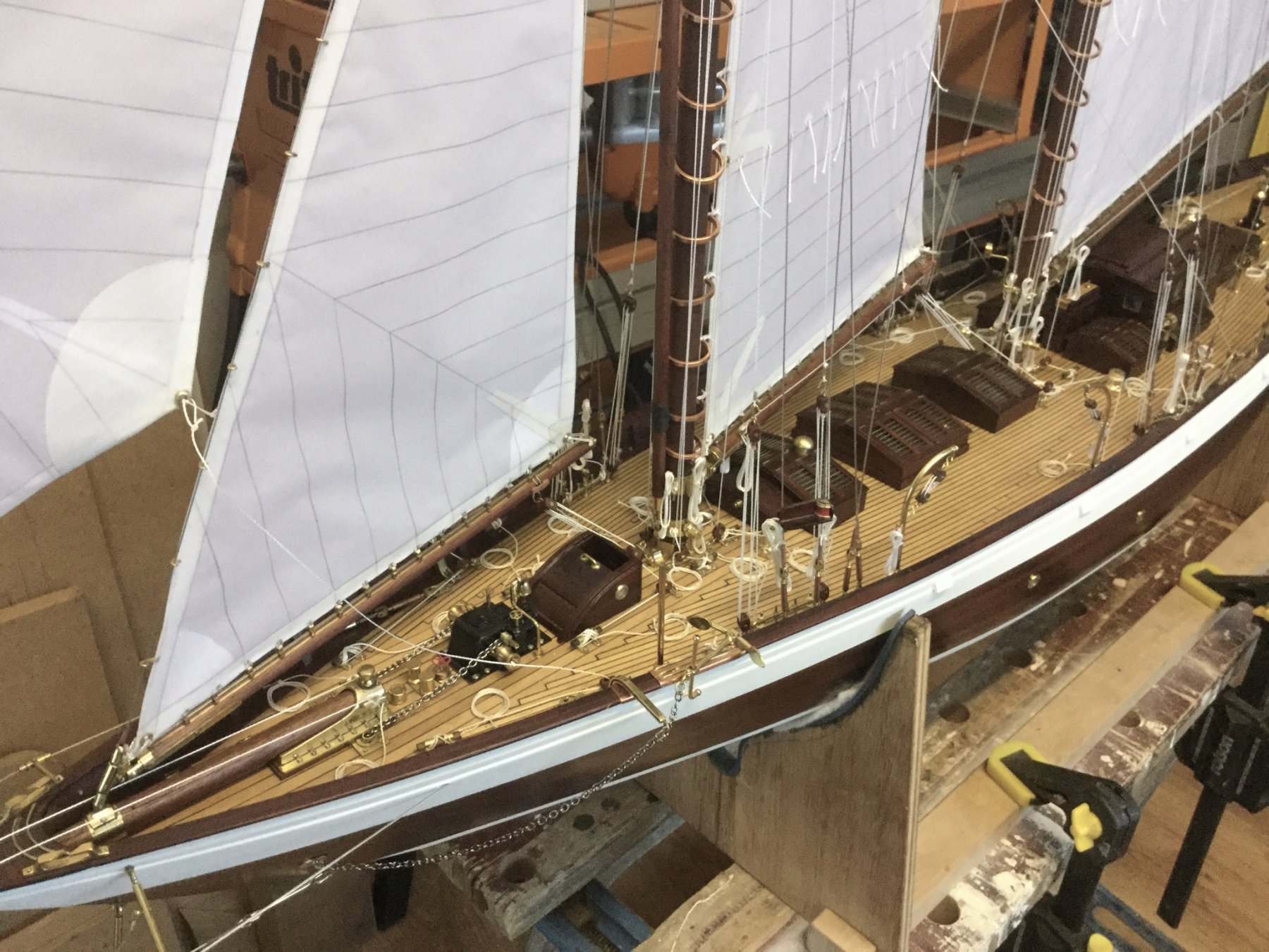
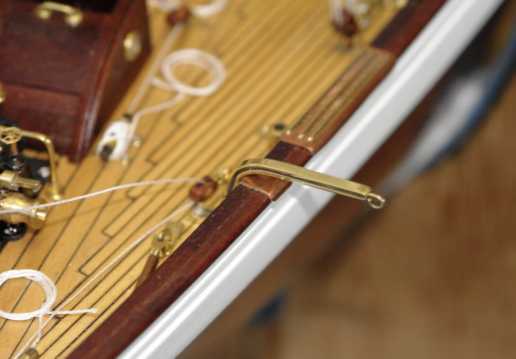
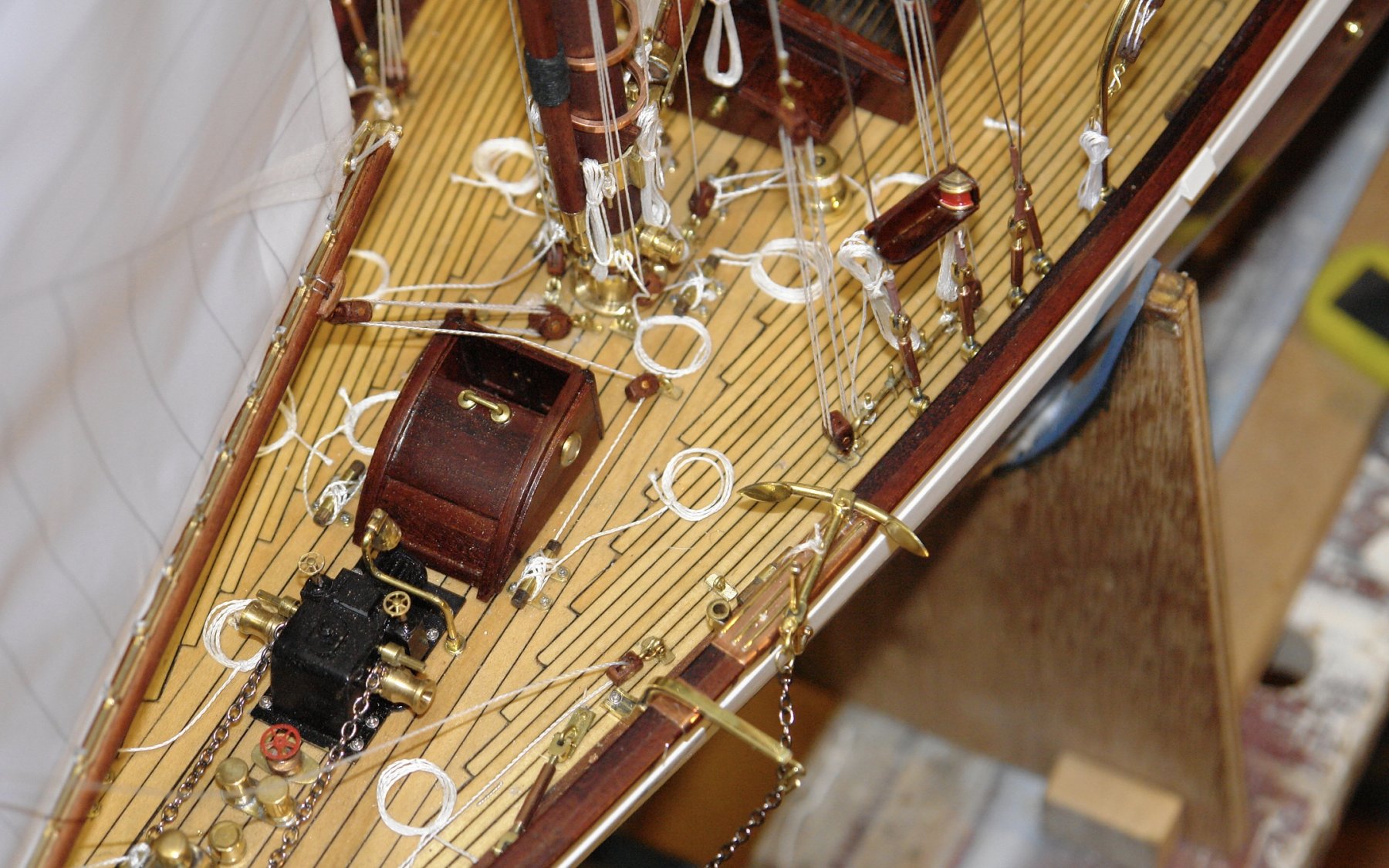
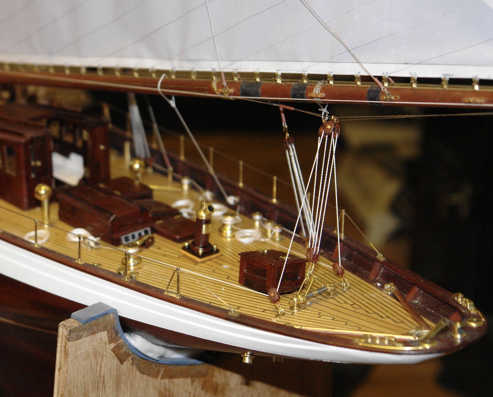
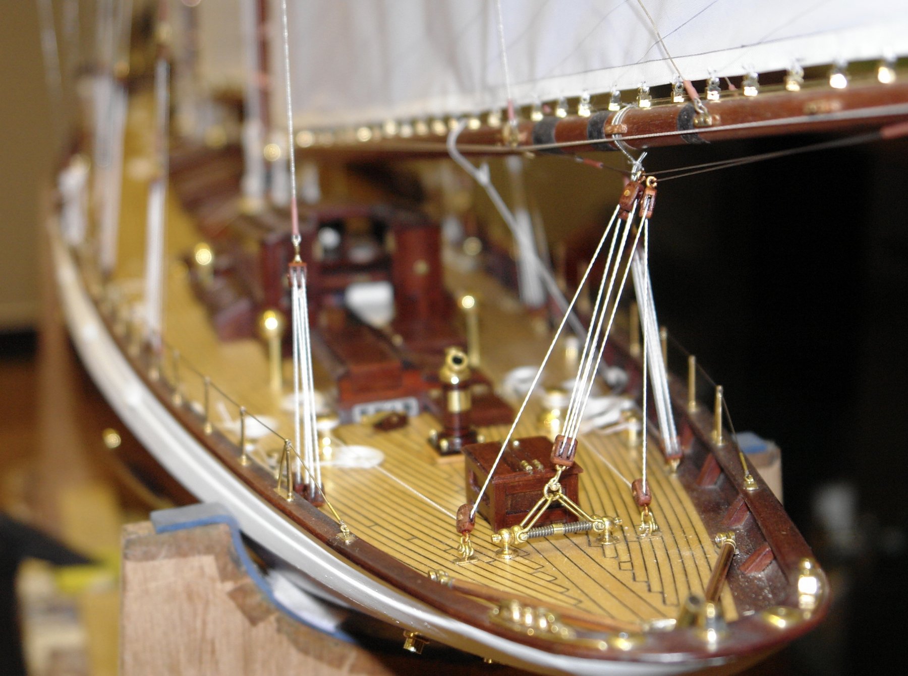
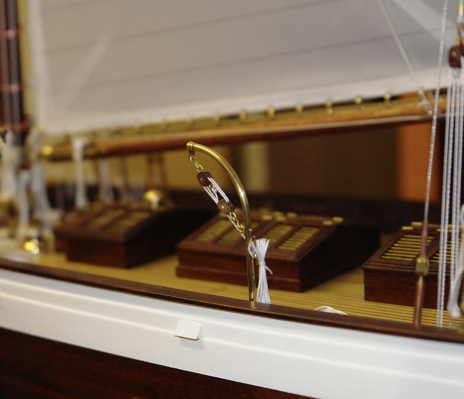
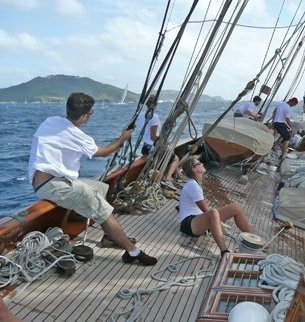
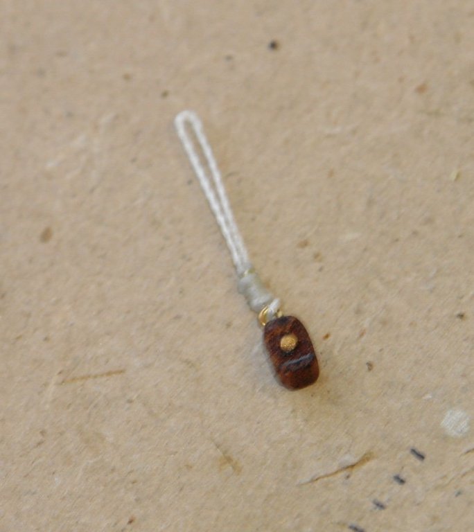
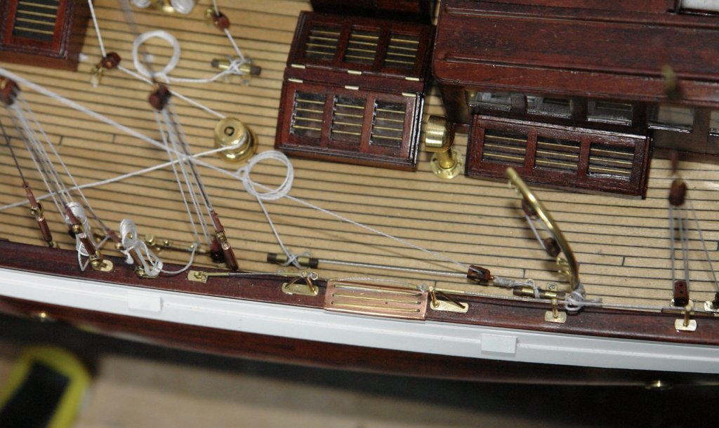
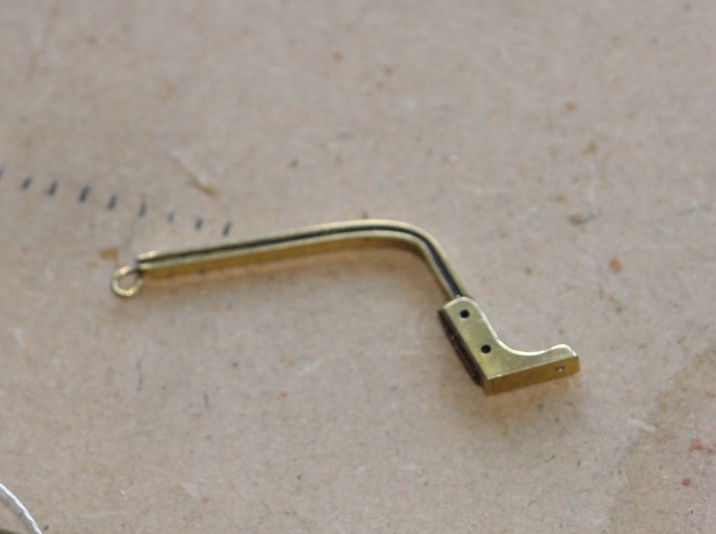
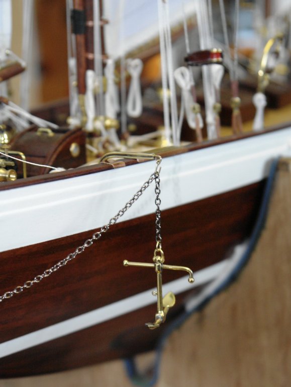
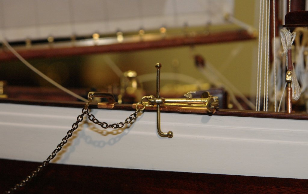
Michael / John (Jim Lad) - thank you for looking in and for the comments. John A - thank you for the additional information I will look them up, it looks like a good lead. And so onward and upward:- I spent some time figuring out how the sheets for the flying jib are rigged - the plans are quiet on this detail. From the following photo I new that the sheets (just visible) landed on the deck abeam of the deckhouses, but from other photos I knew that the only deck hard point at this location was a cleat. Eventually I found the following photo that showed blocks laying alongside the cleat. My presumption is that the blocks are attached to the cleat and moved between cleats to suit various sail sizes and configurations. Anyway on that assumption I made 2 blocks with rope tails and rigged the flying jib sheets accordingly. I then went on to mount the previously made anchors starting with the previously made outrigger. `this was glued and screwed in place (using a spectacle repair screw). The anchor was shackled to the chain and then pinned and glued to the bulwark rail before being lashed in place.


-
Hello Francis. That was a long gap between posts. I don’t always look at the recent posts or my Endeavour build log so it’s a bit of luck I found this, Anyway to your question. I set the mast on my milling machine table wth shims at the tapered end to get it level and the drilled a series of holes. Then I pinned through the channel into the holes. However all you need to do is scribe a line along the length. So how about setting the mast level on a flat table, using shims at the taper end to make it level, the shim thickness needs to be half the difference between the diameters at the large and small end. Tape the mast to the table and shim a pencil so the point is at a height of half the diameter of the large end. Now with the pencil and shim flat on the table draw a line along the length of the mast. This should give you a line against which to place the channel sighting through the holes for the cotter pins.
-
Hello Keith, it it is quite hard to recommend a good place to start with model ship building as the choice is very much dictated by the temperament and skills of the builder. Fortunately skills can be acquired and old dogs can learn new tricks. As for temperament, well that’s a different story as by our age it’s pretty well locked in. So if you are the sort of person who likes quick results, gets bored with hours spent trying to shape components which you struggle to see, or derives no satisfaction from a days effort producing something smaller than a five pence piece then start with something simple and small. If you don’t get bored or frustrated easily and see failure as an opportunity to make it again (and better) then go for something spectacular. Remember however that large complex models can take many years to build and before you start ask yourself if you have the will and stamina to see it through. That said many of us find model making a fascinating and rewarding passtime and a source of great pleasure and pride. Good look with your first build, I look forward to seeing your build log.
-
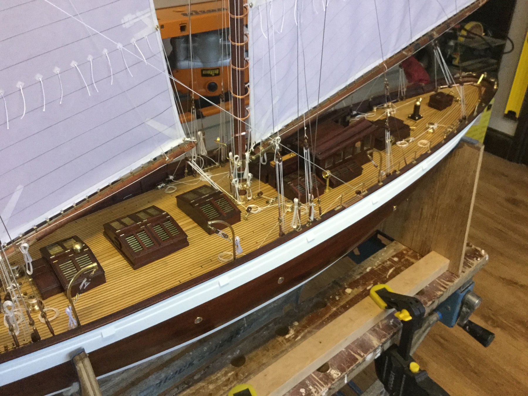
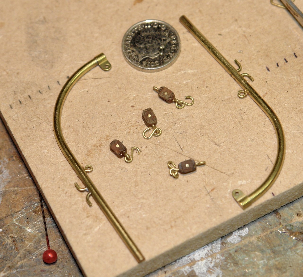
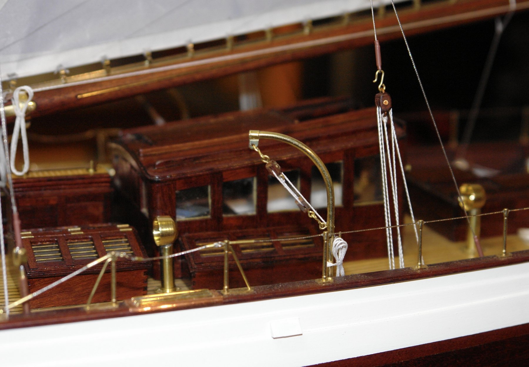
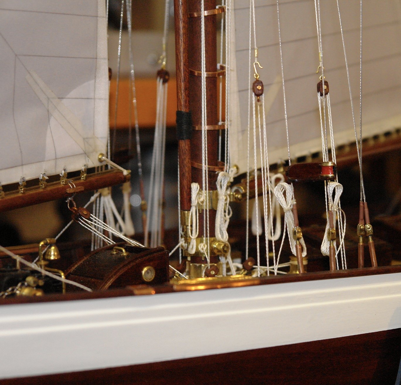
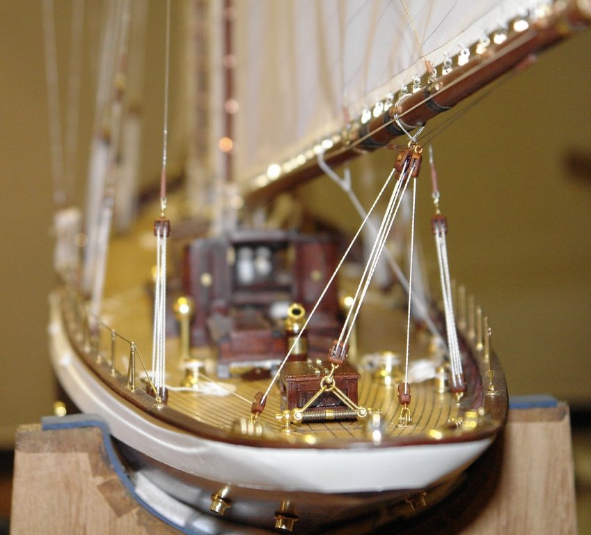
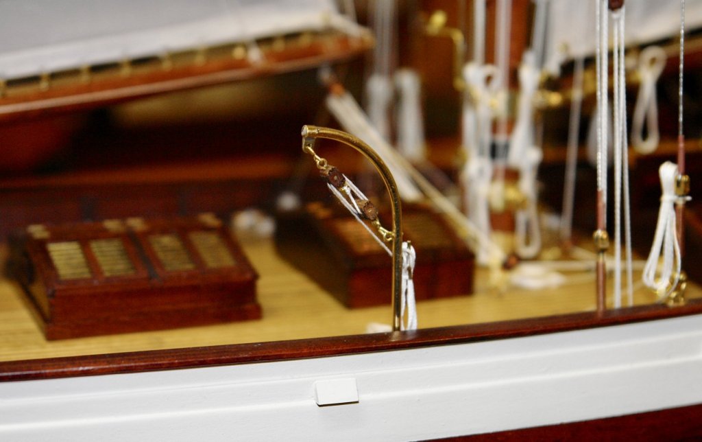
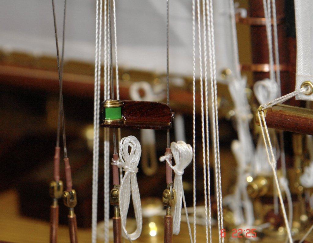
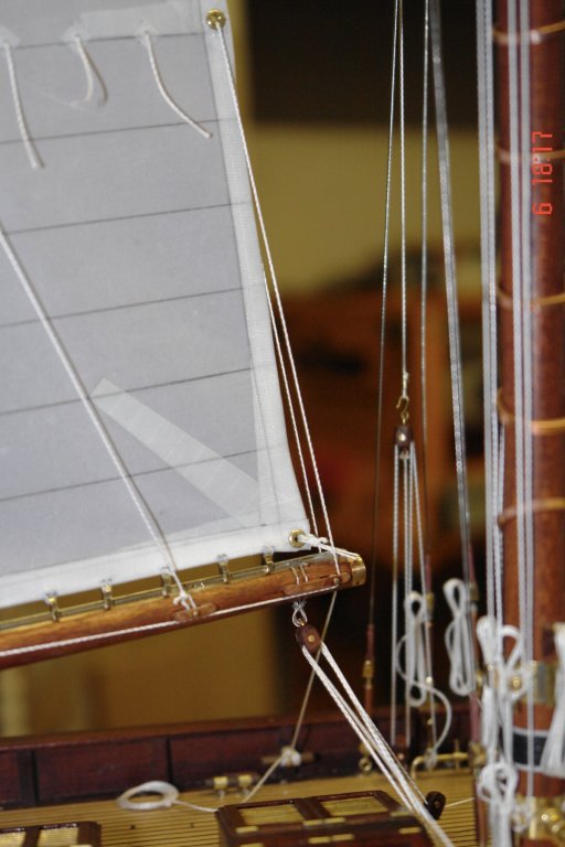
I'm gradually working my way through the final bits of rigging. I could go on for quite a while adding bits of detail. I'm finding the decision on when to stop difficult! I spent some time adjusting the mainsail sheets until I became satisfied with them. I then went on to rig the main topmast running back stays. In the following photo the sheets and the starboard backstay are complete. A while later the port backstay was also complete, I then moved on to finishing the boat and step davits. The davits and blocks had been made earlier. The step davits have single blocks while the boat davits have doubles.


- 882 replies
-
- 11
-
-
Hi John - I may be being dumb but I'm not sure where the link is to Davids post? Also I tried to search for Everson Line Company on Google without success.
-
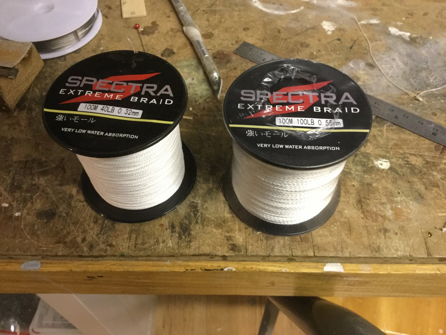
Richard / Dan - thank you for your comments - you are too kind. Noel - Altair is predominantly rigged with modern braided line and hence rope wound on a rope walk isn’t a great match. I searched the internet for braided line and came up with the following fishing line that can be bought in a wide range of thicknesses and several colours. It gave an acceptable approximation to what I was looking for and it slips round the blocks nicely and has virtually no stretch. It was bought on ebay.

-
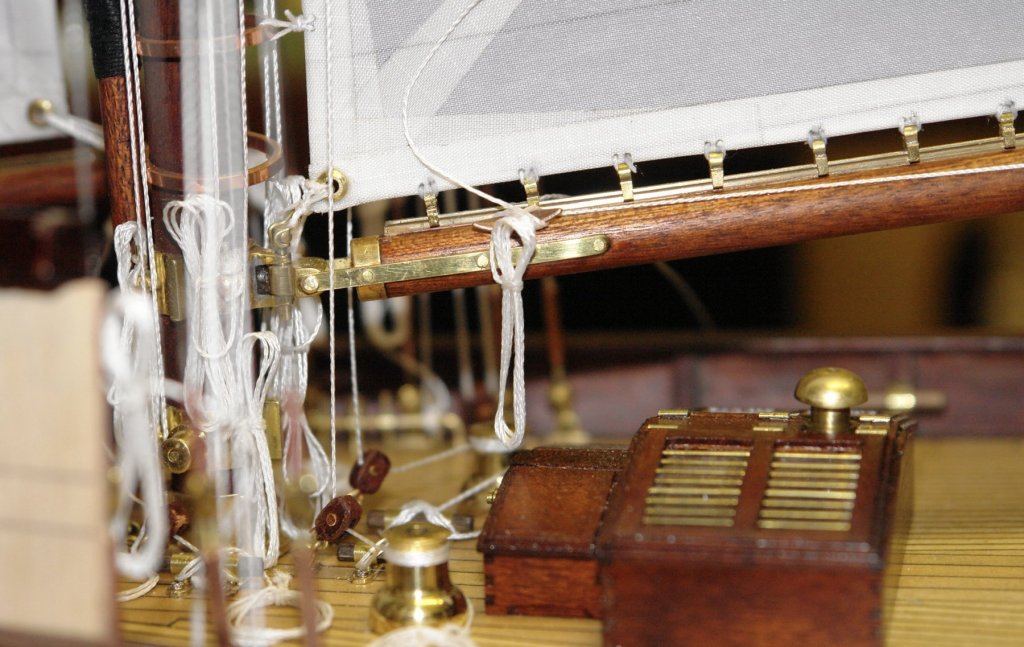
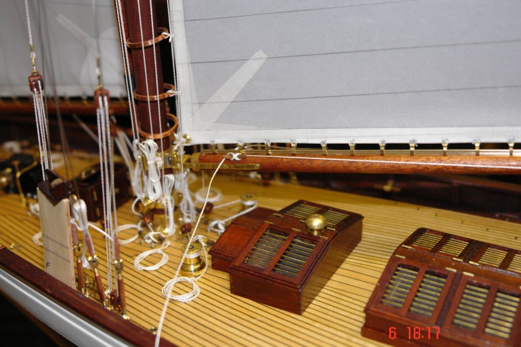
I made the navigation lights and housings and mounted them on the shrouds I then rigged the reefing lines on the fore and mainsails.

-
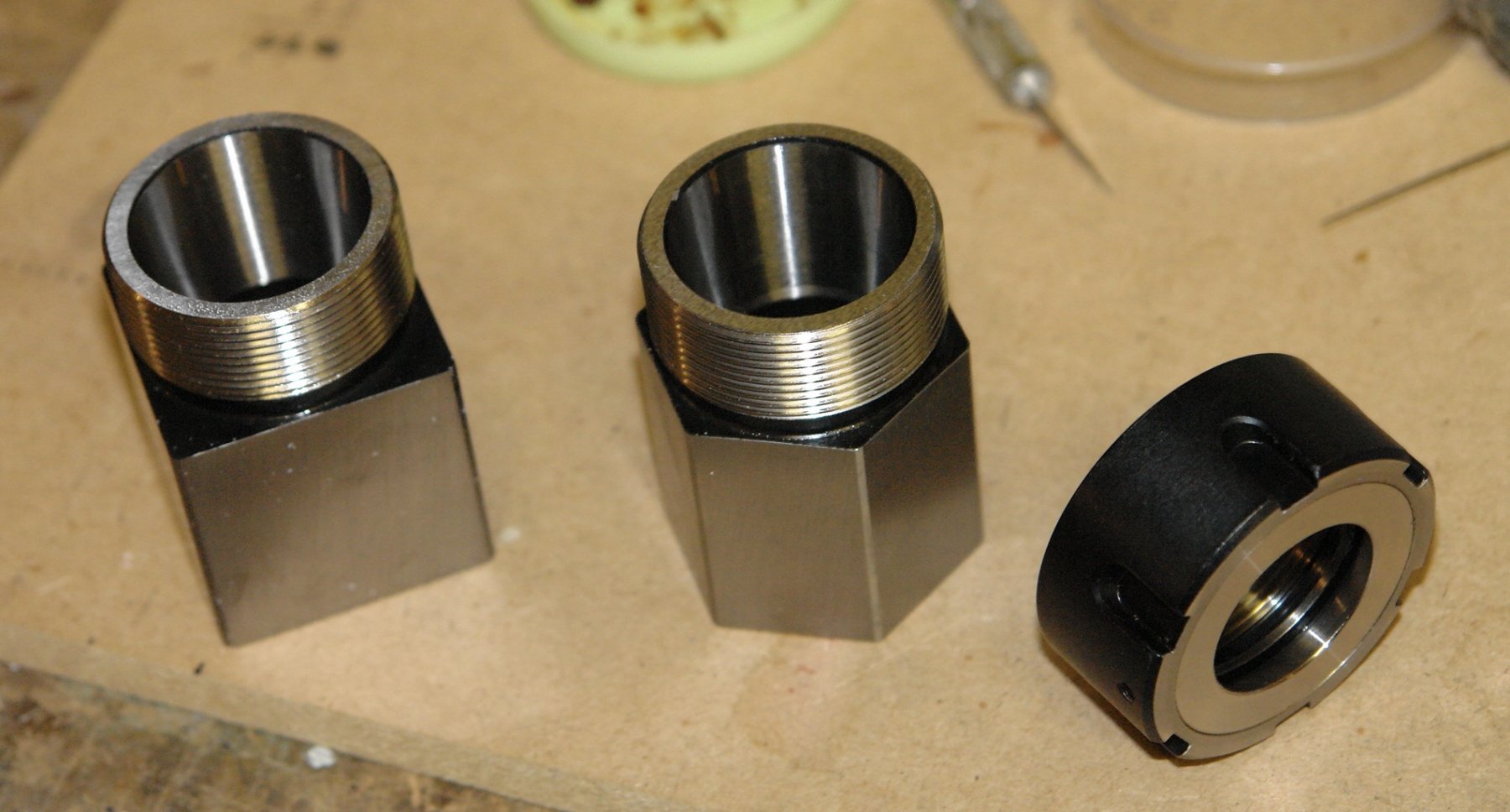
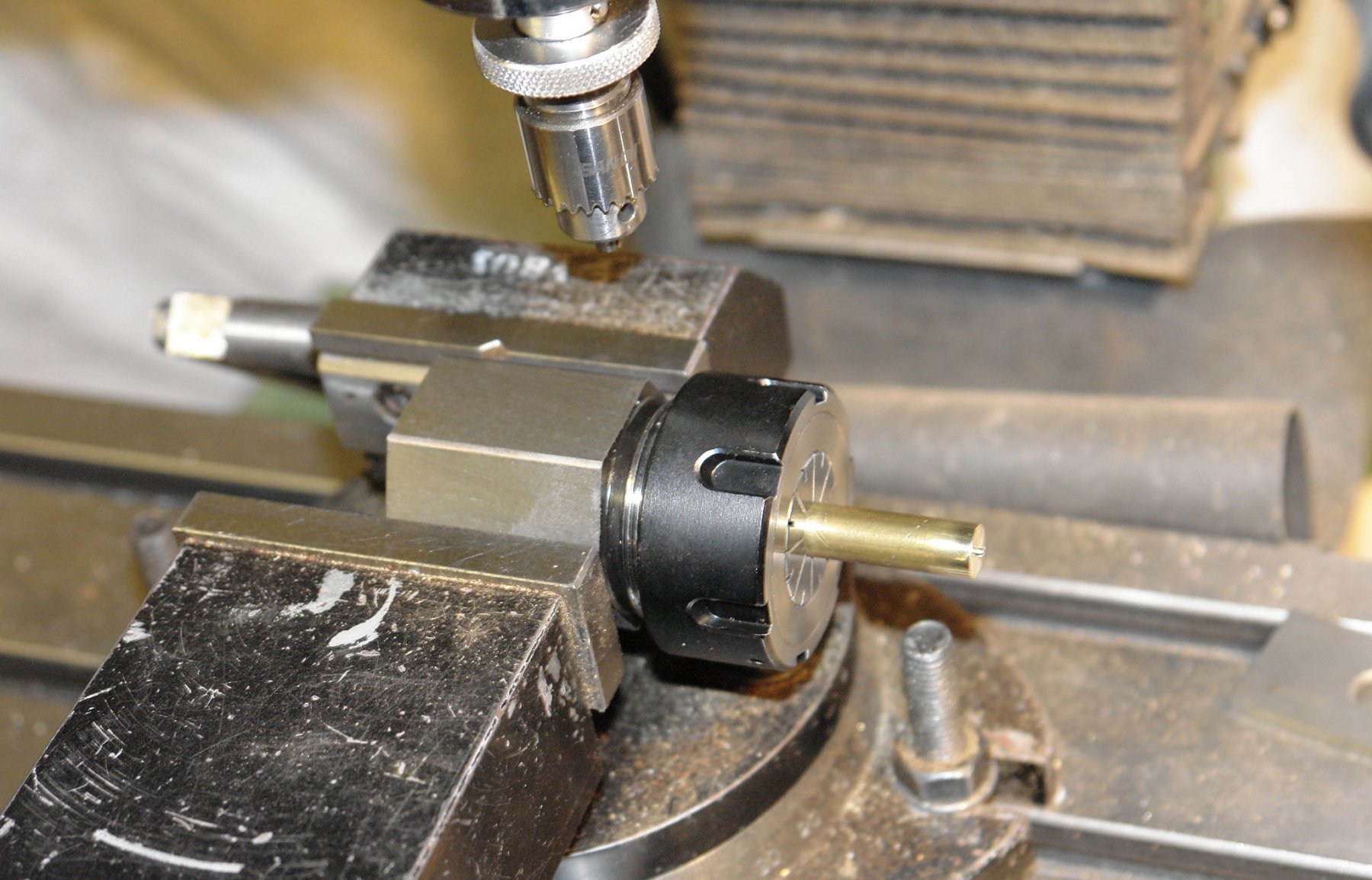
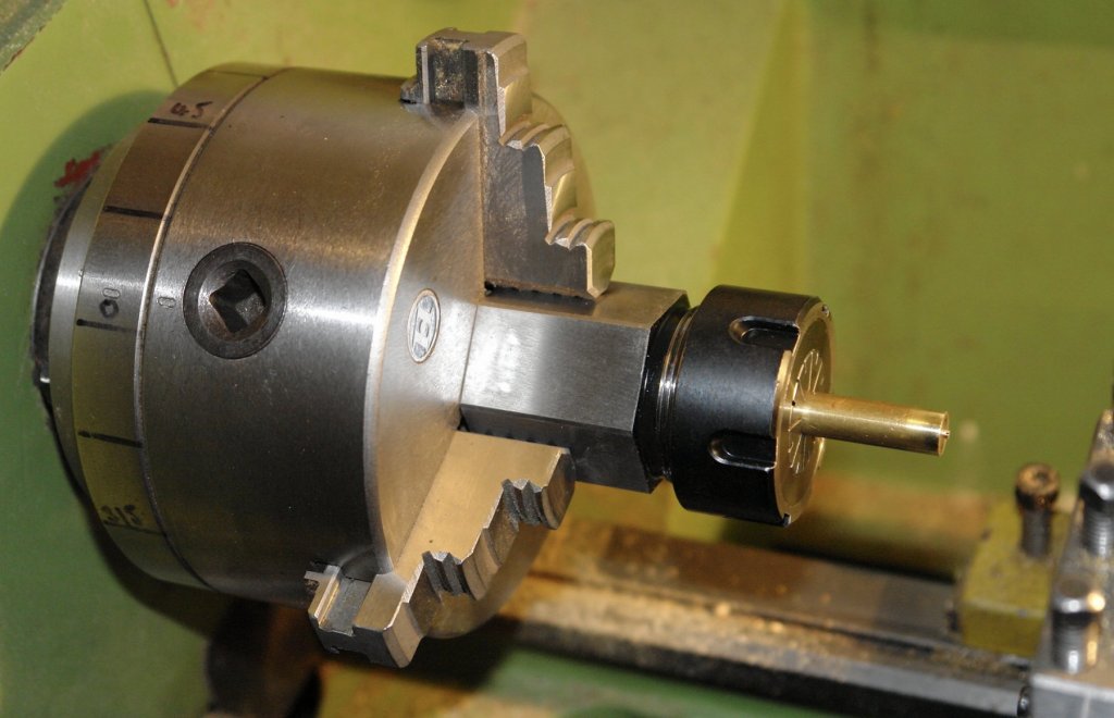
Collet blocks are used to simplify the milling of square and hexagonal shapes on round bar. The block use standard ER collets and are available in ER25, 32 and 40 sizes. If you are like me and don't have a collet chuck on the lathe you can mount the hex block in the 3 jaw lathe chuck or the square block in the 4 jaw chuck. The accuracy of the set up depends on the accuracy of the lathe chuck. Fortunately mine is pretty good. By using the collet chuck I can hold smaller diameter bar (down to .040") and of course I avoid the jaws damaging the bar. I bought mine from www.arceurotrade.co.uk - they ship abroad.


-
Hi Jon The diagram I put in your post was from "The Gaff Rig Handbook" by Leather. Unfortunately he isn't letting on what to do with the tails.
-
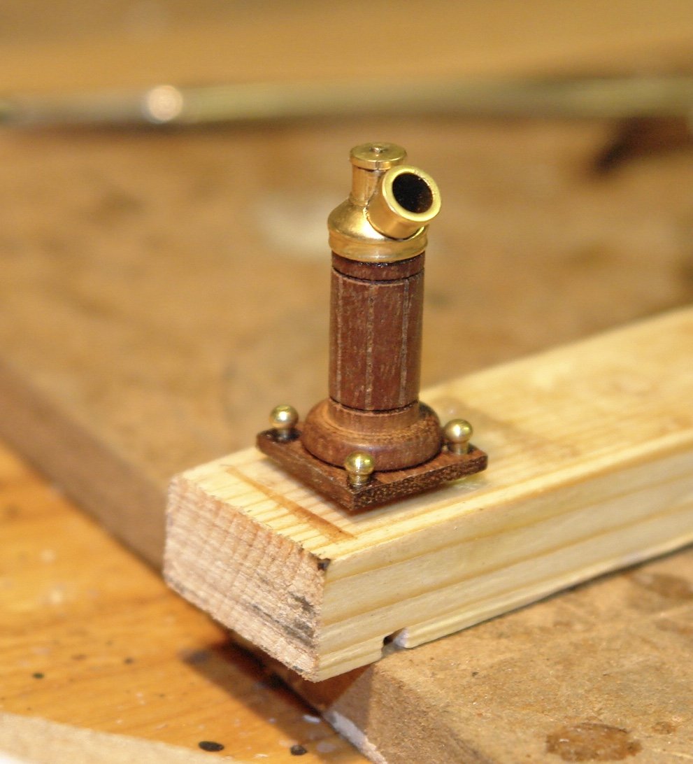
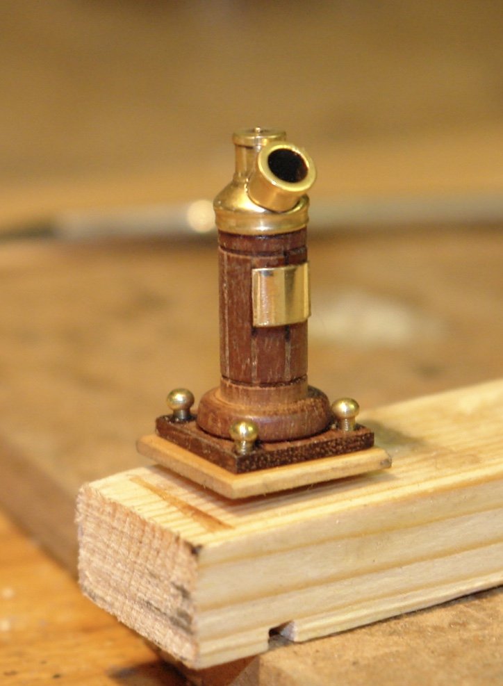
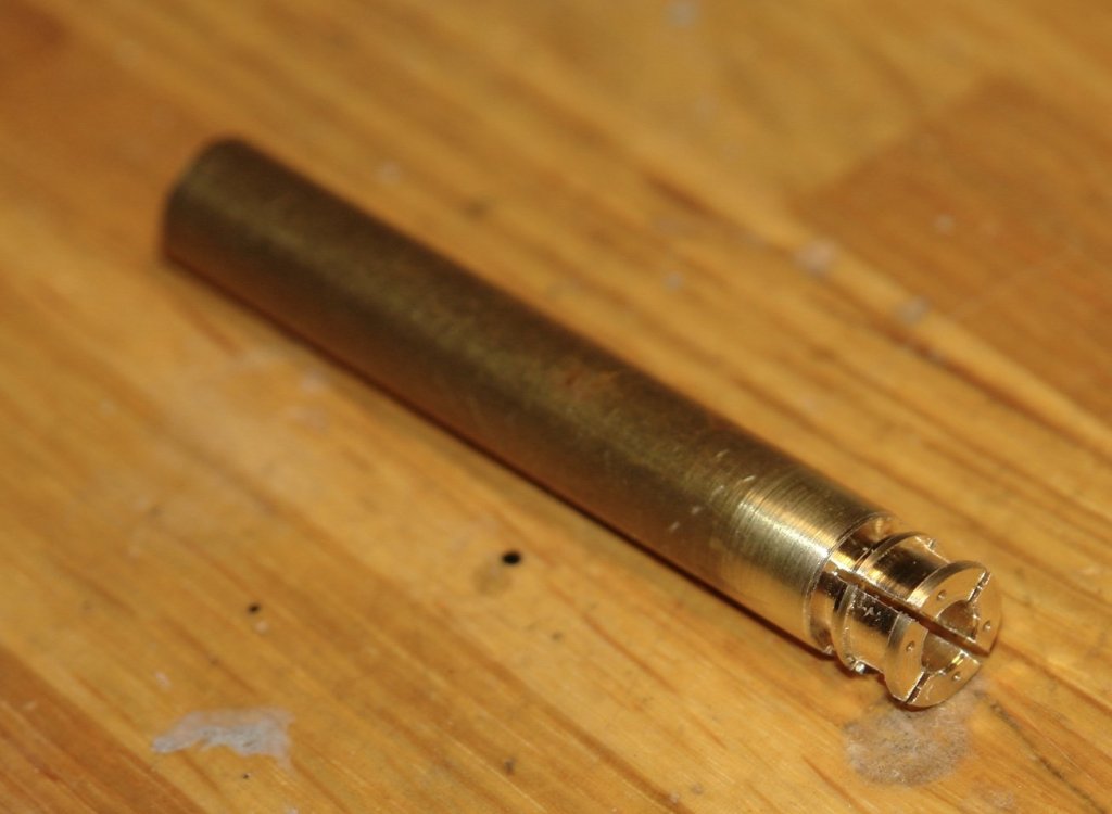
Thank you Richard. Preparations for Christmass and family visits have disrupted the build somewhat but today I got back not there workshop for the first time in over a week. My schedule going forward is looking better so I hope to make more progress over the next 2 weeks. Some time back I had a go at the binnacle but on checking my photo library i raised I had missed off the mounting plinth and the brass access plate. So I corrected the error, painted it with poly and mounted it on the deck. Its about 1 inch high. I then made a start on the mountings for the port and starboard lights. I turned the basic shape of the lights and segmented it into quarters of which I only need 2.


-
Nice launcher Kevin. It would have grieved me to have paid for it.
-
Nice work Jon. Have you thought how you will lower the centre of gravity for sailing. On the plans for the sailing version of Altair the suggested modification is to attach a separate lead keel on a skeg some 4 inches below the level of the real keel. The technical reason for this is that scaling down does not work if you want good sailing performance. Sail area varies as the square of the length while displacement varies as the cube. The result is that if you do a true scale model it has too little displacement and much too much sail area. Im sure from your previous builds of sailing yachts you are aware of the problem. The Altair plans also show a sailing rudder that has about twice the area of the scale rudder.
-
Nils, cleaning all those small spaces between decks requires specialist skills. Can I suggest you buy one of these. https://www.google.co.uk/search?q=model+figures+cleaner&ie=UTF-8&oe=UTF-8&hl=en-gb&client=safari#imgrc=thgAXWf_HUfN_M:
- 692 replies
-
- 5
-
-
- eagle of algier
- chebec
- (and 2 more)