KeithAug
-
Posts
3,986 -
Joined
-
Last visited
Content Type
Profiles
Forums
Gallery
Events
Everything posted by KeithAug
-
 Hello Kees, it will be good to see how this one turns out. Hope you are keeping well and the job hunting is on track.
- 193 replies
-
- 7
-

-
- wilhelmina vii
- fishing
- (and 1 more)
-
Mitbok, it would be interesting to know how you made the turnbuckle?
-
Hi Nils. Interesting model and a good start. Some of the frames are quite thinly cut, what did you use to cut them?
- 692 replies
-
- 5
-
-
- eagle of algier
- chebec
- (and 2 more)
-
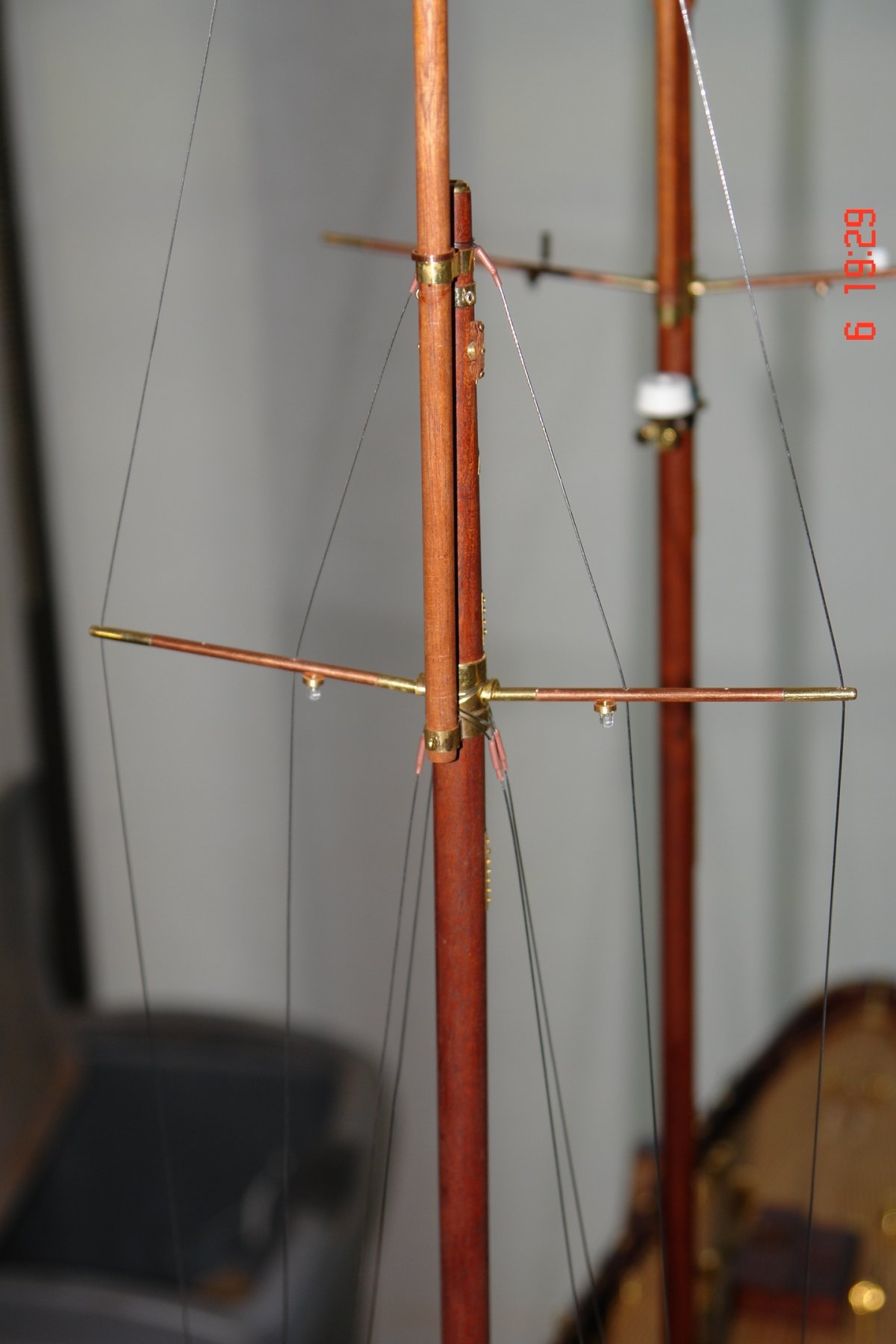
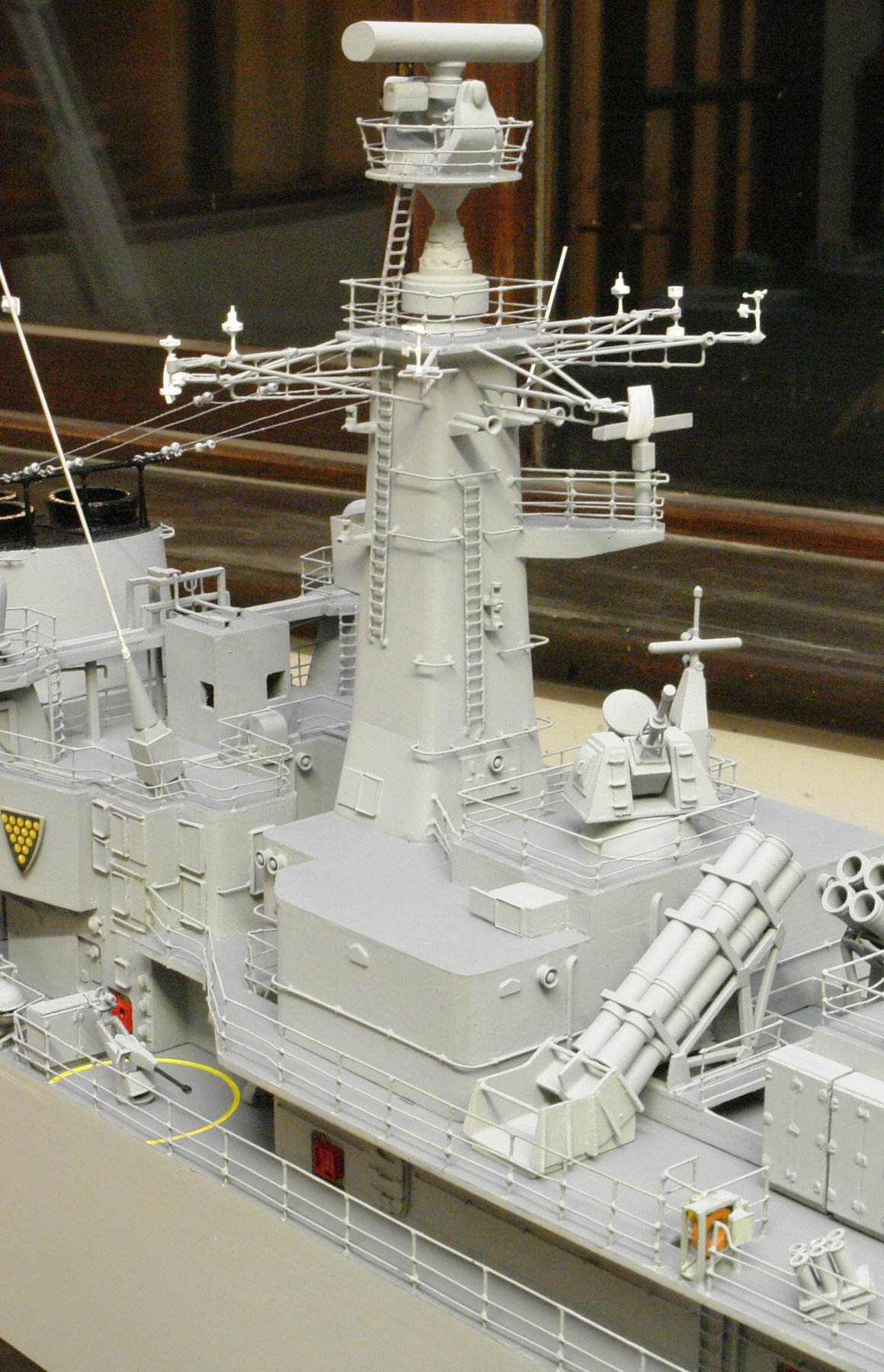
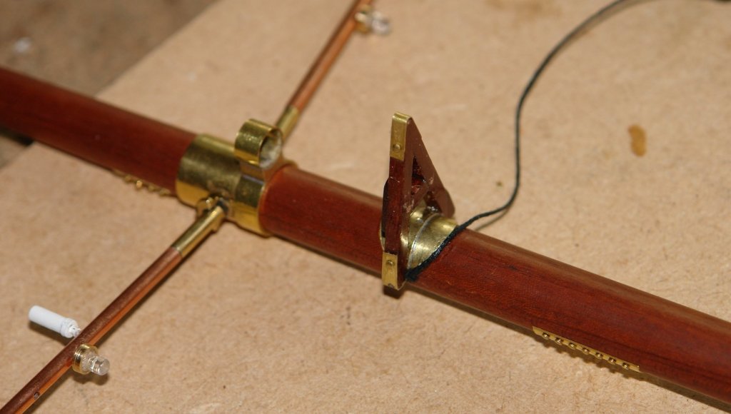
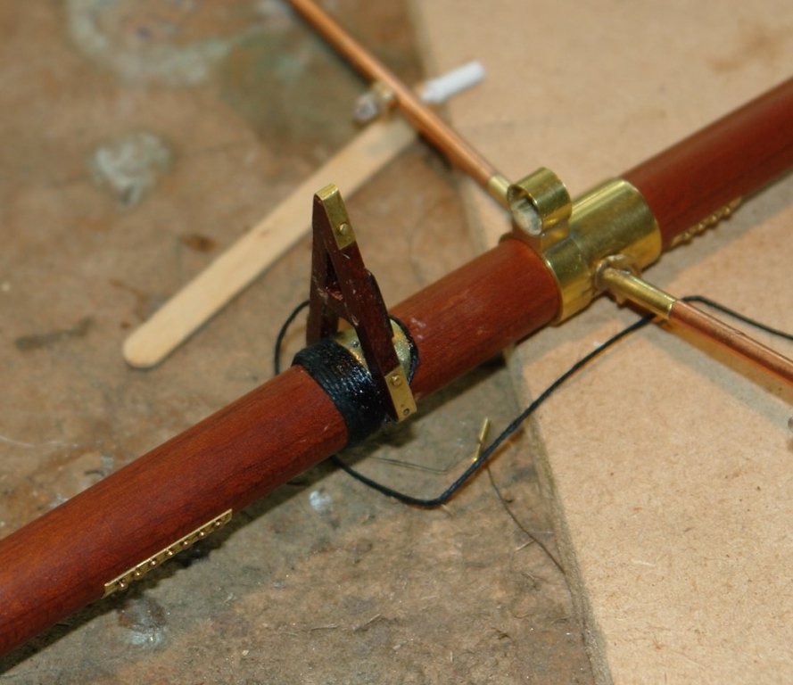
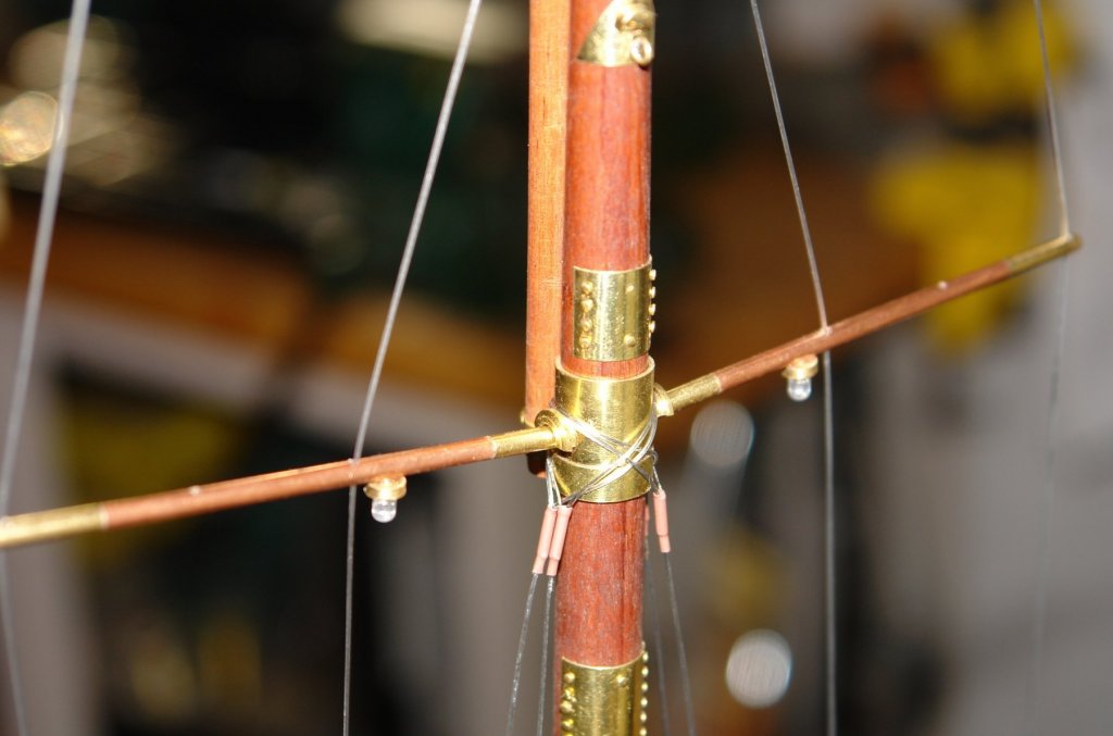
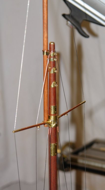
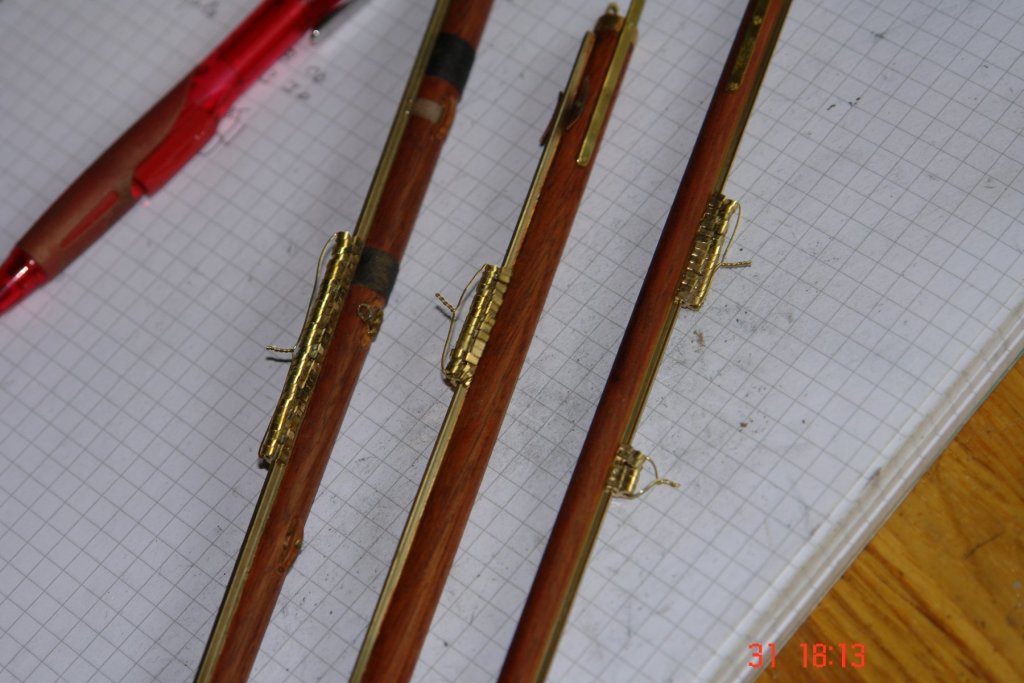
A little progress (yesterday and today) with the rigging. Altair standing rigging makes use of a lot of steel cable terminated with fittings. Fortunately no need (or desire) for many hours serving lines. But first I had to mount the radar / horns "A" frame on the main mast. I glued it in place and then did the bindings to reflect the detail on the real thing. The "A" frame, radar and horns were made some time ago and reported in an earlier post. And then on to the standing rigging for the fore mast - the shrouds are in place but I have now run out of braided beading wire - ebay to the rescue.


- 882 replies
-
- 13
-
-
Bedford Its always good to get a friendly reminder, no need to be sorry. Derek Thank you for your comment.
-
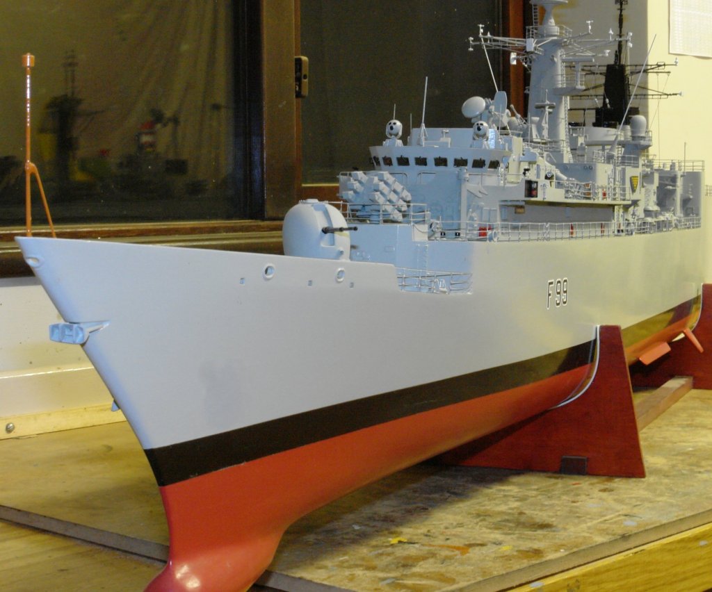
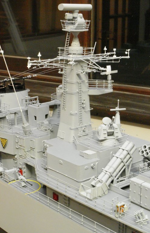
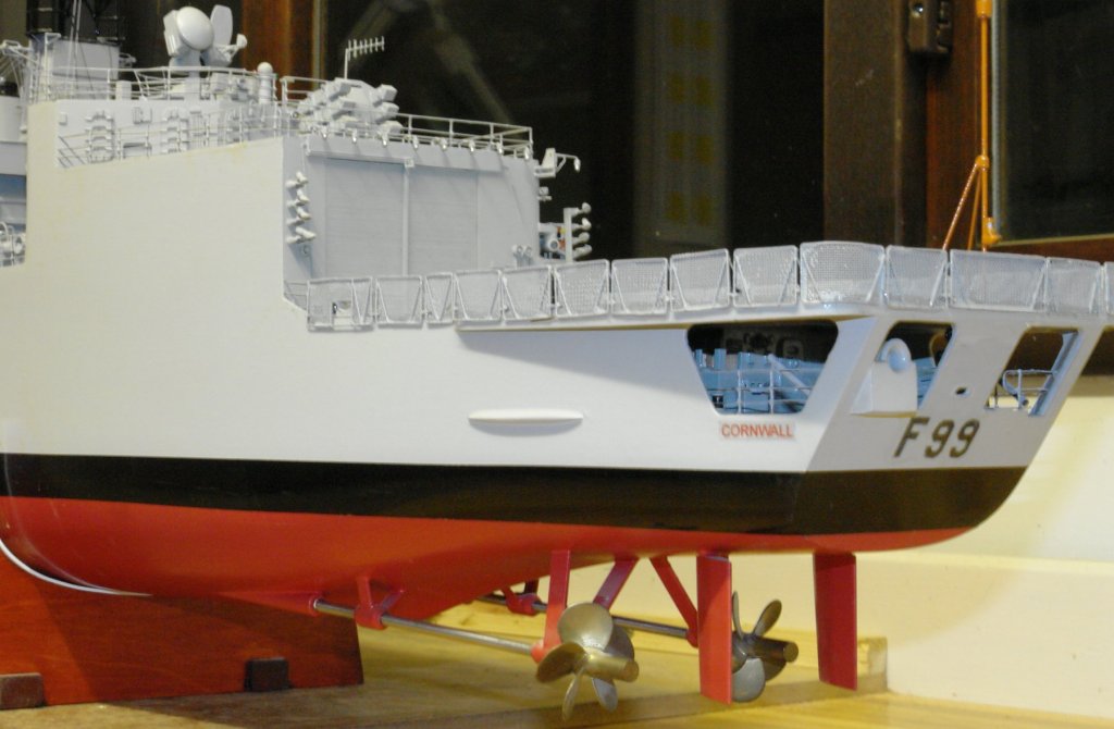
Kevin - you can see more detail of my type 22 here - you may have to join to see it. http://modelwarshipsuk.informe.com/forum/post41038.html?hilit=hms cornwall#p41038 Modelwarshipuk is a pretty good site for Royal Navy warships.
-
Kevin - its my age, I of course meant type 22. I have never used fleet scale plans but I did find Jecobin to be generally fine. Not sure why it would be on the fleet scale forum - but anything seems possible in this virtual world.
-
Kevin - are they Jecobin plans? I built a type 22 to their plans but supplemented them with a lot of photographs. I built the superstructure from 1/32 thick plywood - it has a deal more stiffness than plasticard. Here's my type 22 for interest. I'm enjoying your build, its coming along well.
-
Hello Bedford. I thought someone might pick this up. I was fairly confident because I laid the floor and built the frame for the french doors. However you caused me to recheck, fortunately spot on. Nils and John, thank you for visiting and for your kind words. John I'll be watching how that canoe develops and Nils when is the next keel laying ceremony?
-
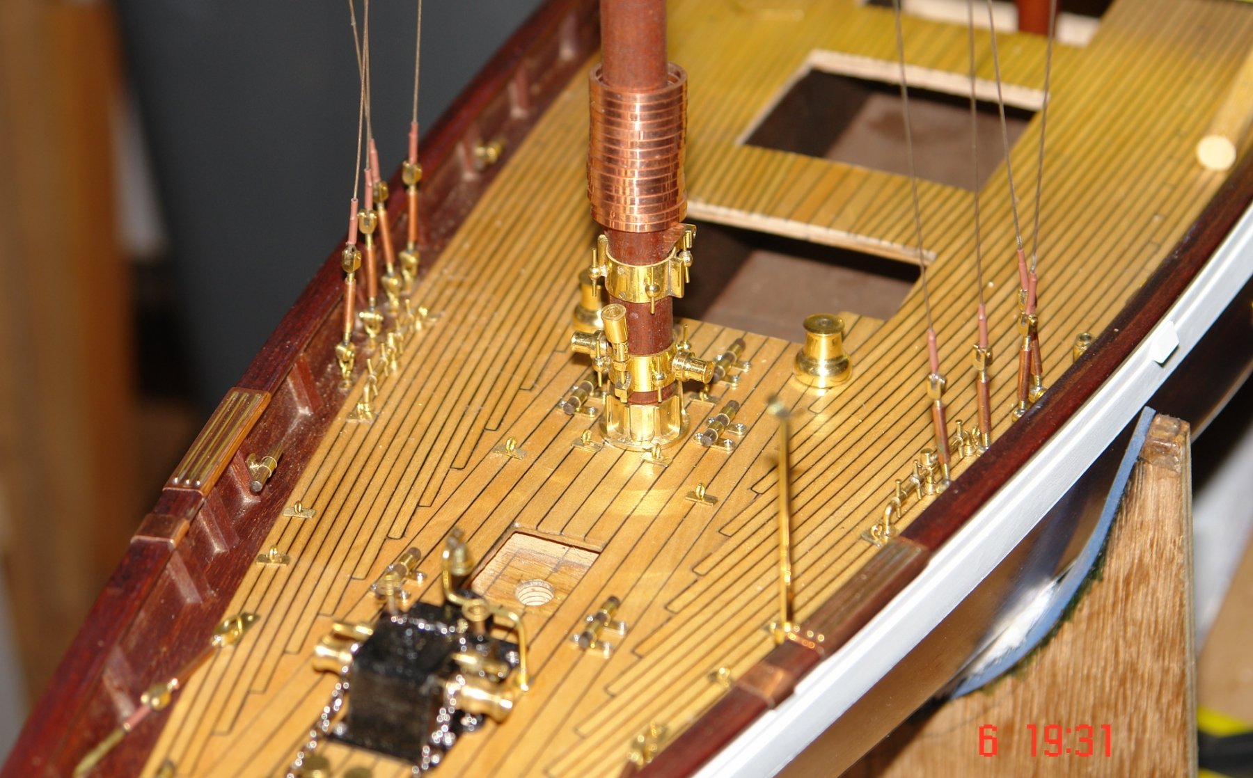
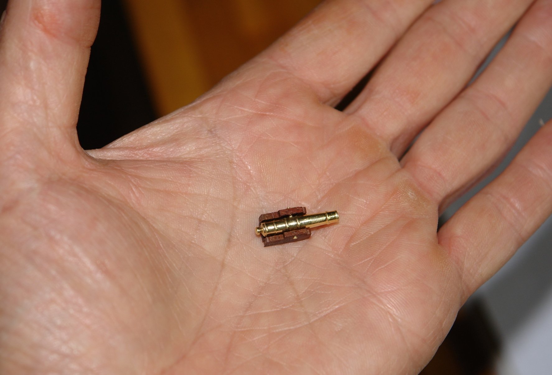
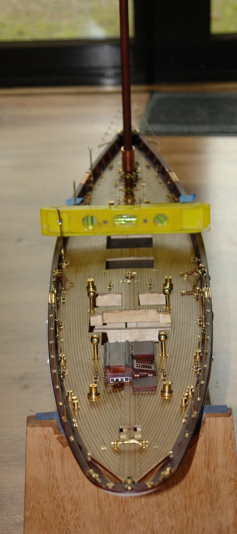
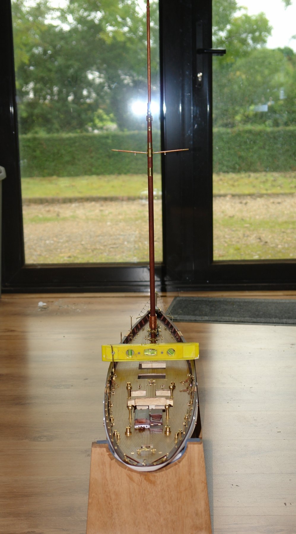
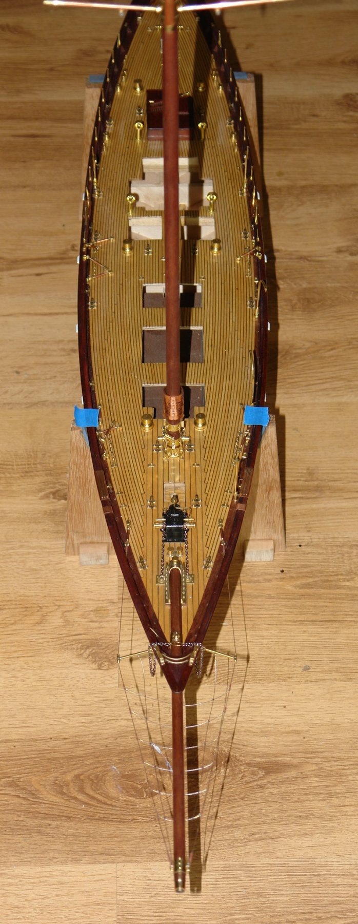
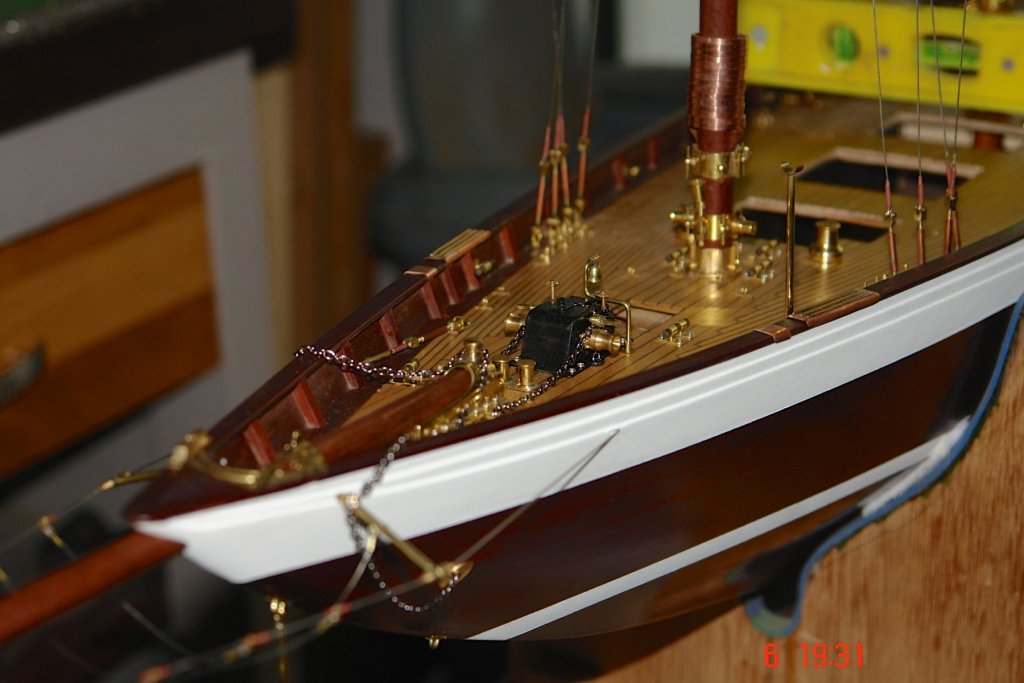
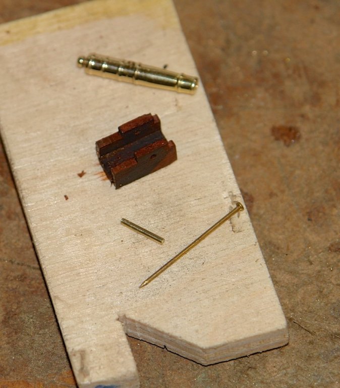
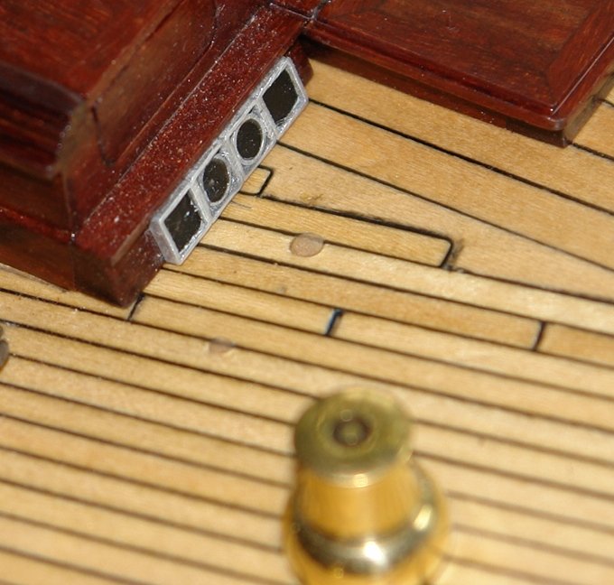
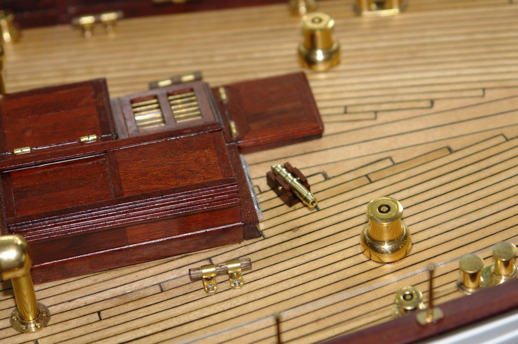
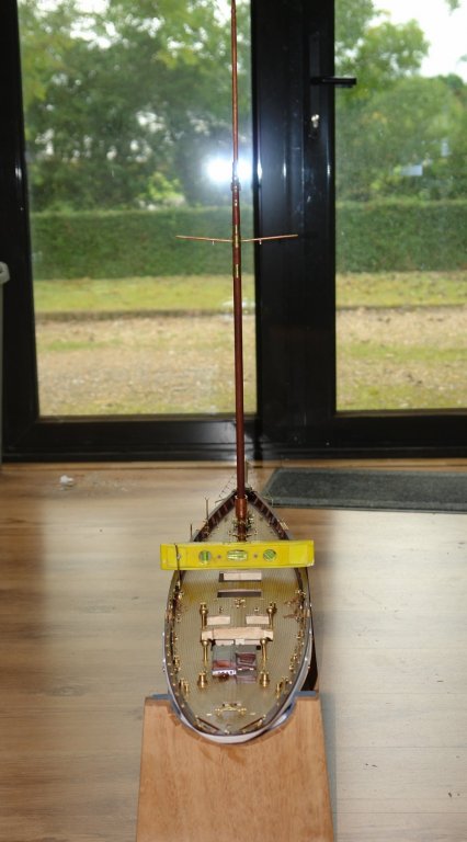
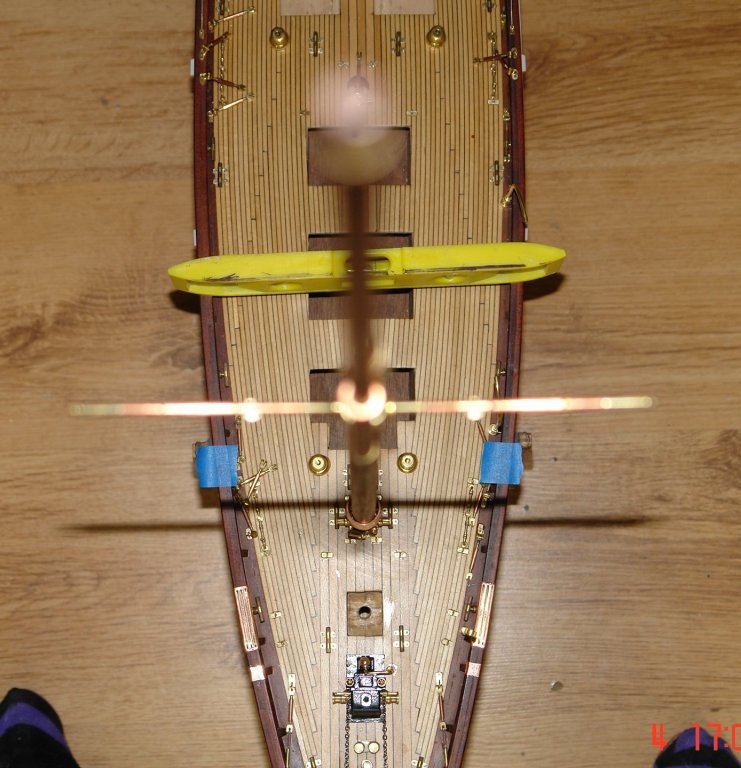
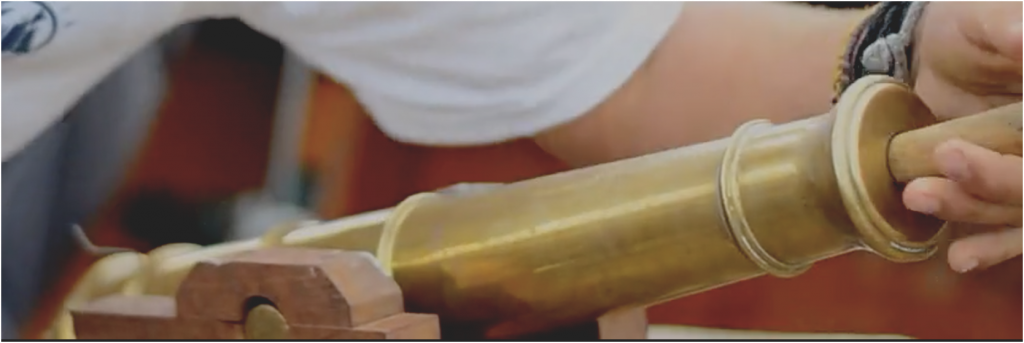
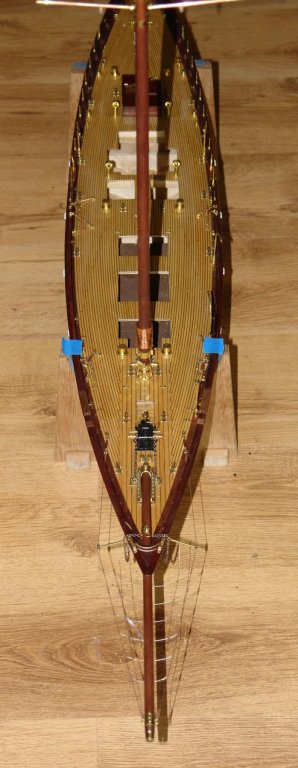
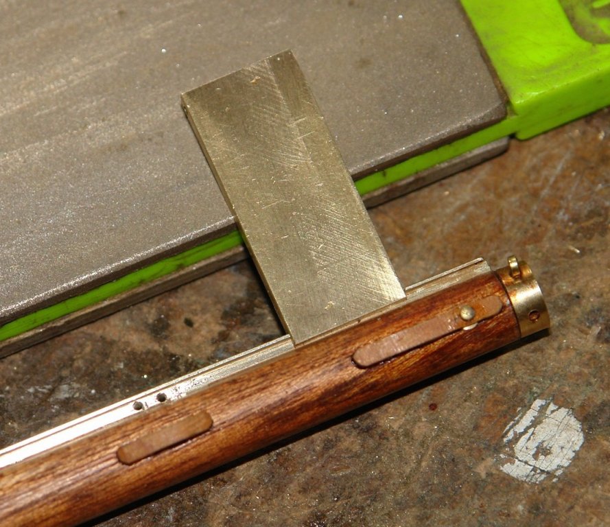
Thank you Per. I find I get a bit drawn into the detail. I wonder if my skills are up to doing something so I give it a try, if it does not work I try again. Sometimes I give in, but most of the time I get comfortable with the result ( Acceptance is helped by my eyesight not being as good as it once was). Once again thank you to all the other visitors. I think I mentioned earlier that I had drilled a couple of holes in the wrong place on the deck. The larger one in particular was bothering me. I considered a couple of options for hiding it including a coil of rope and a drinks tray with wine and beer. Not particularly satisfied with either option I was pleased to be struck by a "flash" of inspiration. The saluting cannon was featured in one of the videos of Altair. I moved on to stepping the fore mast. Verticality, rake and rotational position were all a bit of a concern so I took a deal of care with numerous repeat checks. I started by levelling the hull across the beam and ensuring that the waterline was parallel to the workshop floor. I also marked the rail on either beam with blue masking tape aligned to the ribs. I then used precision eyeballing to sight the athwart ships verticality against the frame of the workshop french doors . To fix the rotational position I sighted down the mast aligning the yards against the blue tape. The process was assisted by the camera flash and the shadow it cast. The rake was set by sighting against the workbench legs (to the side of the yacht).


-
Thanks Richard, I know many would have made a perfect job of a thread solution - I did wonder about setting the thread into the correct shape using PVA glue or similar, but in the end decided I was more confident using beading thread. Michael, thank you. I'm pleased you think it looks good.
-
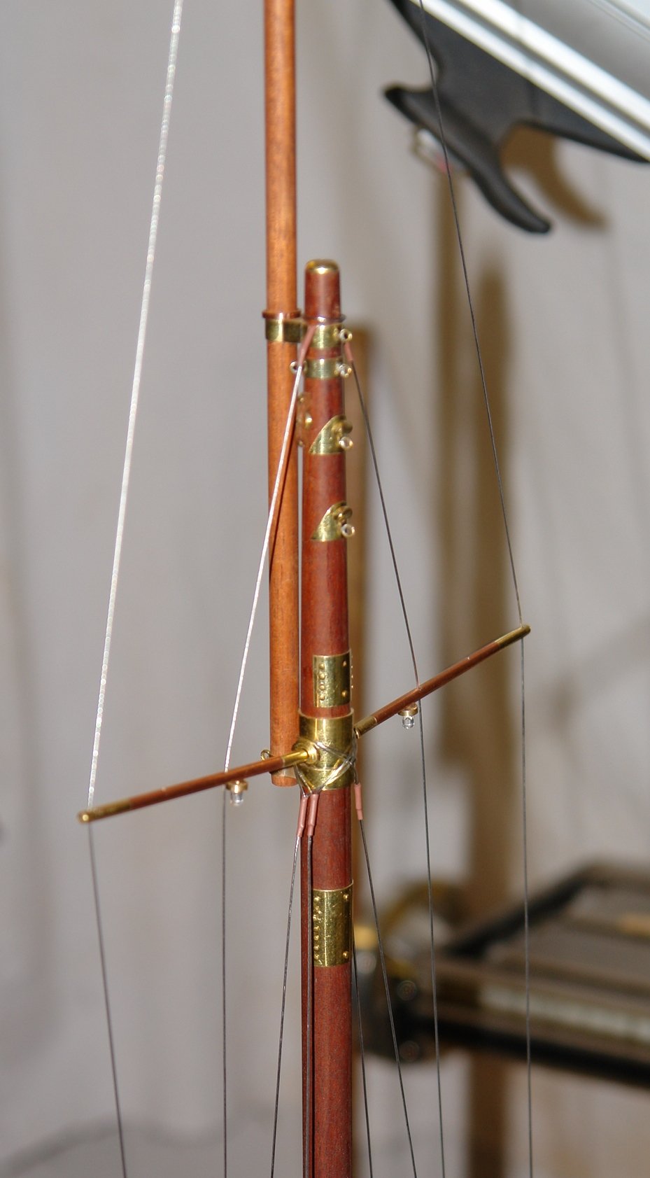
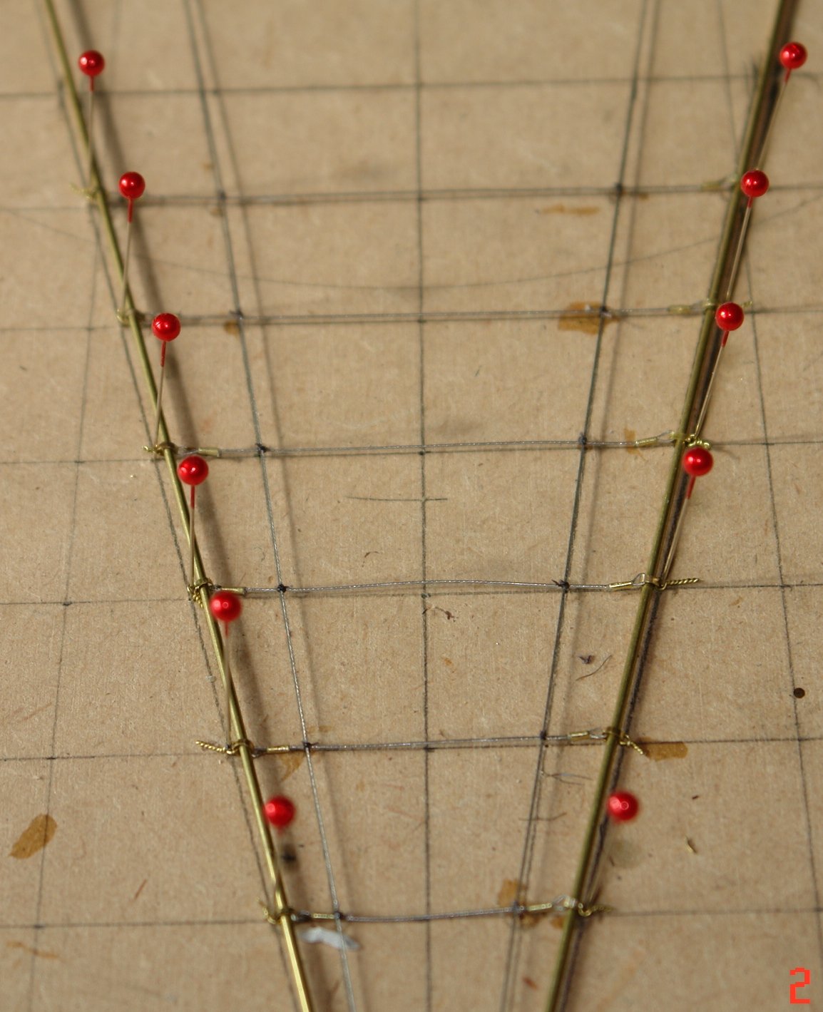
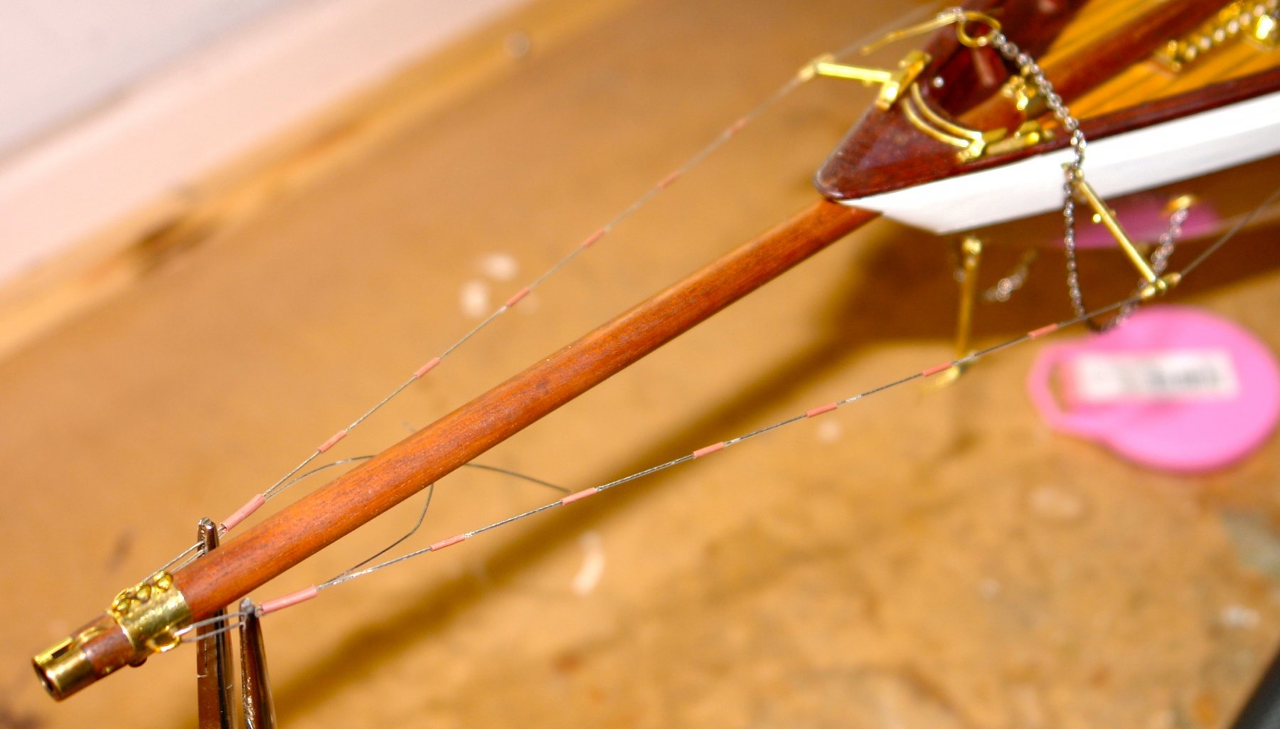
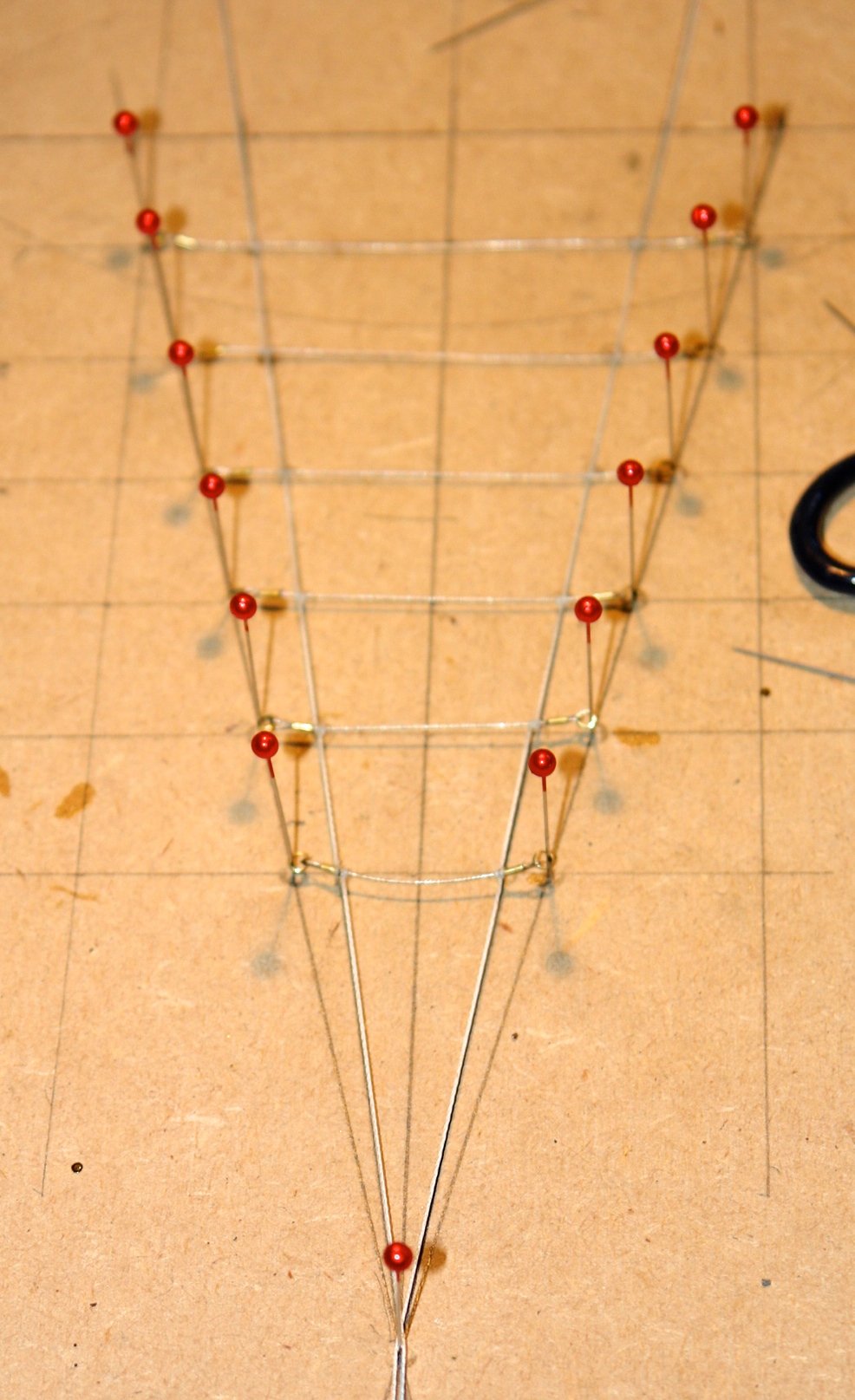
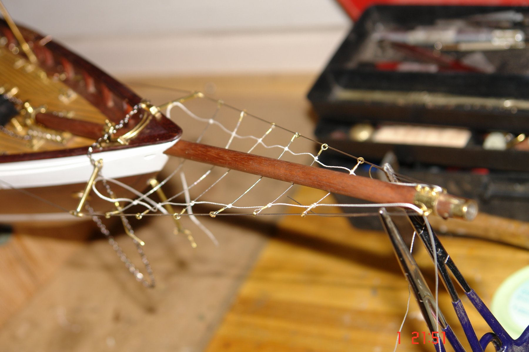
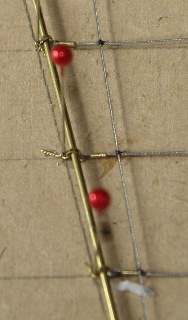
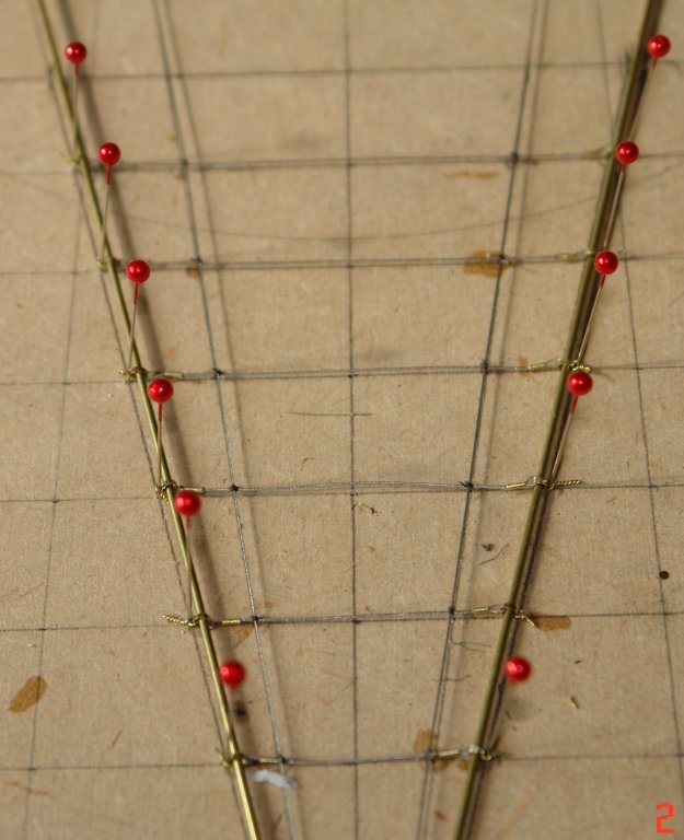
Thanks Richard, However I started today by trashing yesterdays work for a few reasons: 1, I couldn't get myself convinced that the fishing line would hang in a natural curve. 2, I realised that by not paying great attention to the orientation of the hoops on the ends of the athwartship braided wire that I had introduced a twist that made them want to follow a serpentine path. 3, I didn't feel that I had allowed enough belly below the bowsprit. So it went in the bin and I was glad that I had made all those extra end hoops. To solve the fishing line problem I decided to resort to further use of braided wire, it may not hang under gravity but the shape is more controllable. Fixing the orientation of the end hoops required a bit of a development of the building jig as follows:- Two brass rods (.040" diameter) were slotted through the hoops at each end of the athwartship lines during their manufacture - thus eliminating any twist caused by them being aligned on different axes. To give more belly I widened the base of the jig (drilled wider spaced pin holes). The finished assembly of lines and fittings felt a bit more workmanlike. The longitudinal lines were tied on with cotton thread and then secured with a spot of CA. I then went back to the shrouds and fitted the heat shrink tubing to simulate the protection at the attachment points. Fortunately the heat gun arrived at lunch time. The shrouds are temporarily fitted, tensioned and held with surgical clamps. With the protection completed the clamps were removed and the shrouds were slotted through the end hoops on the athwartship lines. The shrouds and the the longitudinal lines were then secured and the end hoops crimped on to the heat shrink on the shrouds. The resulting shape felt pretty good.


- 882 replies
-
- 12
-
-
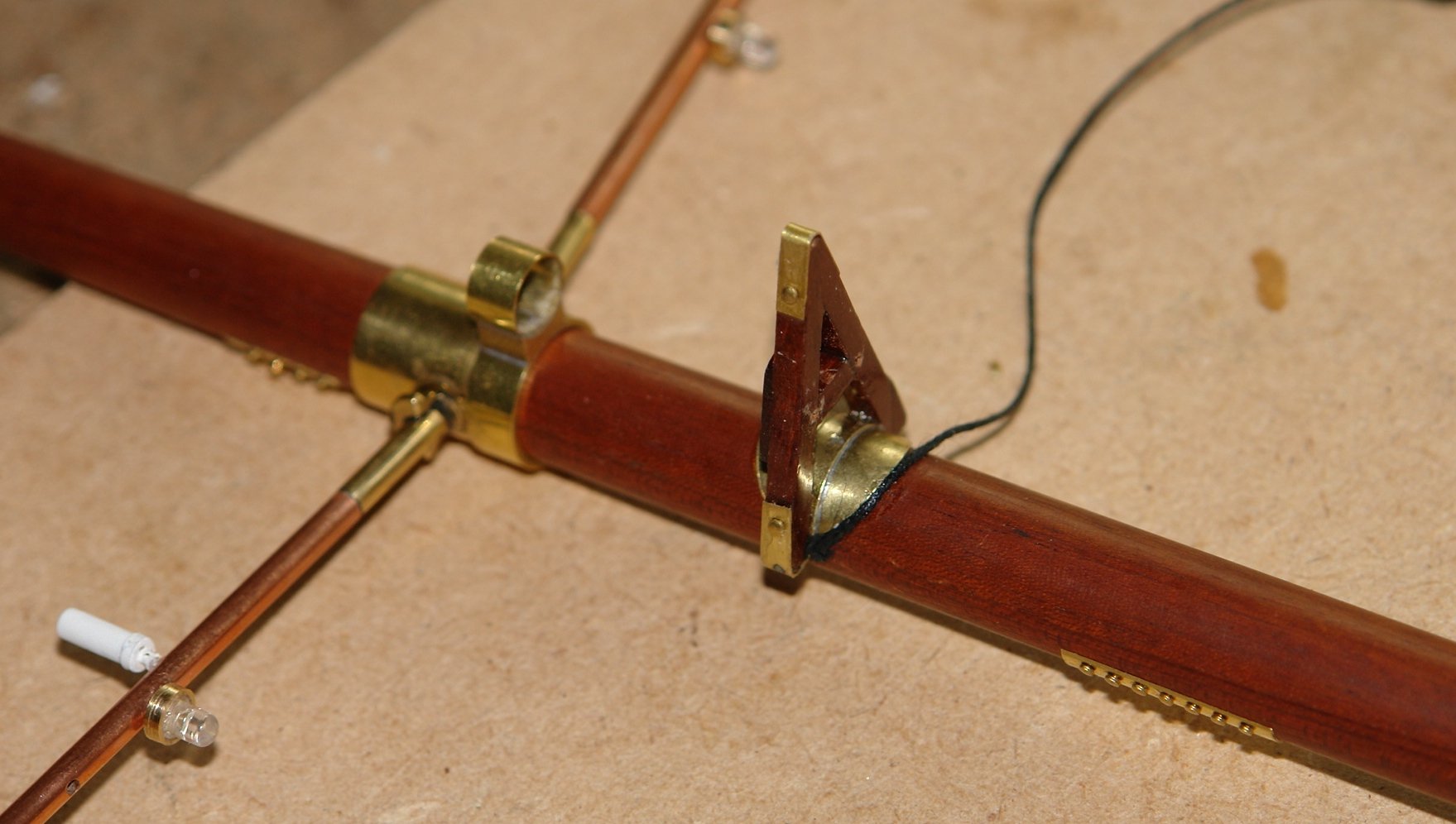
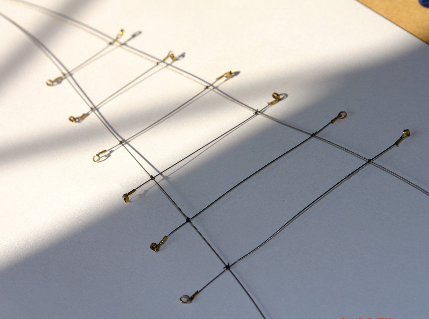
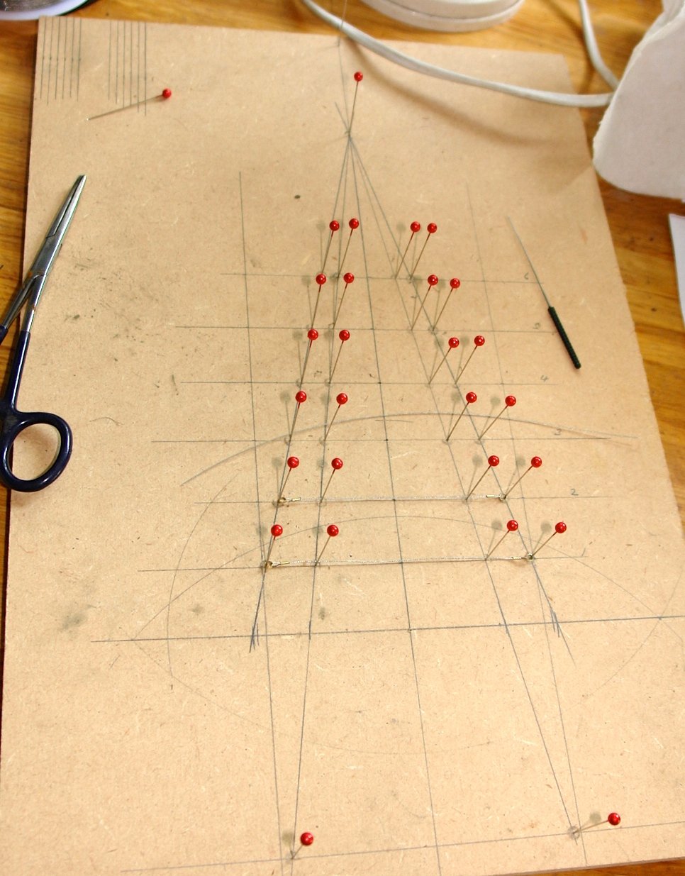
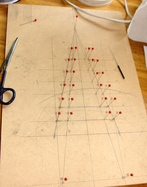
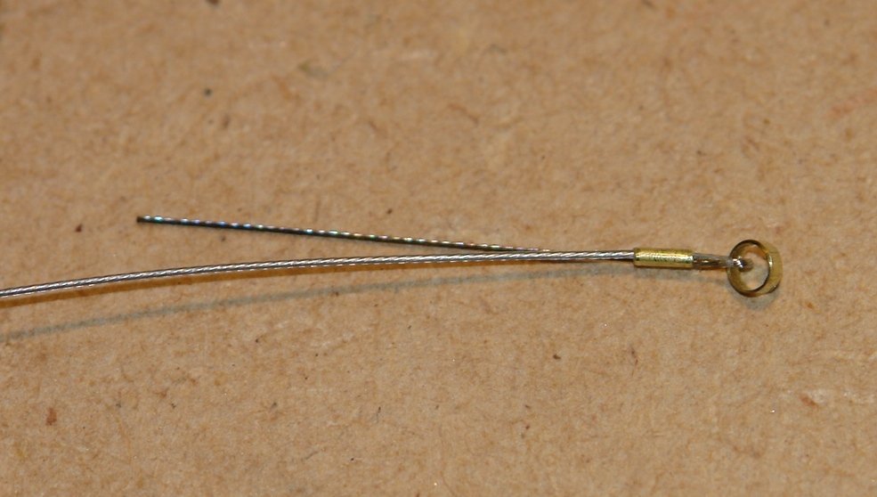
Today I spent some time progressing the bowsprit rigging. I am conscious that loose lines don't hang realistically because they are stiff relative to their weight. Because of this I decided to make the athwartship lines from .017" beading wire. I decided I needed a jig on which to make the bowsprit rigging - this was quickly knocked up from MDF and pins. The base of the triangle was a little wider that the distance across the martingale struts to give the belly to the lines. The ends of the athwartship lines were made by looping the wire through a .040" thin wall tube. The hoop on the end is the attachment feature for the bowsprit shrouds. In the next picture the 6 lines are compete and the port and starboard longitudinal lines (braided fishing line) have been tied. All a bit tricky to see - sorry. The whole thing is loosely fitted in place. I really need the hot air gun I ordered.


-
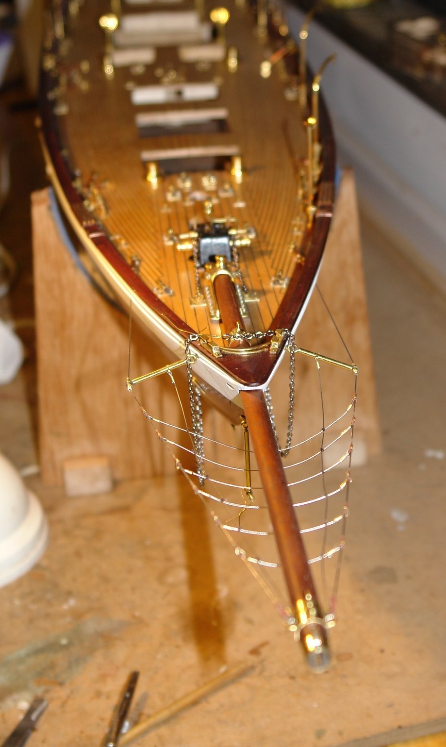
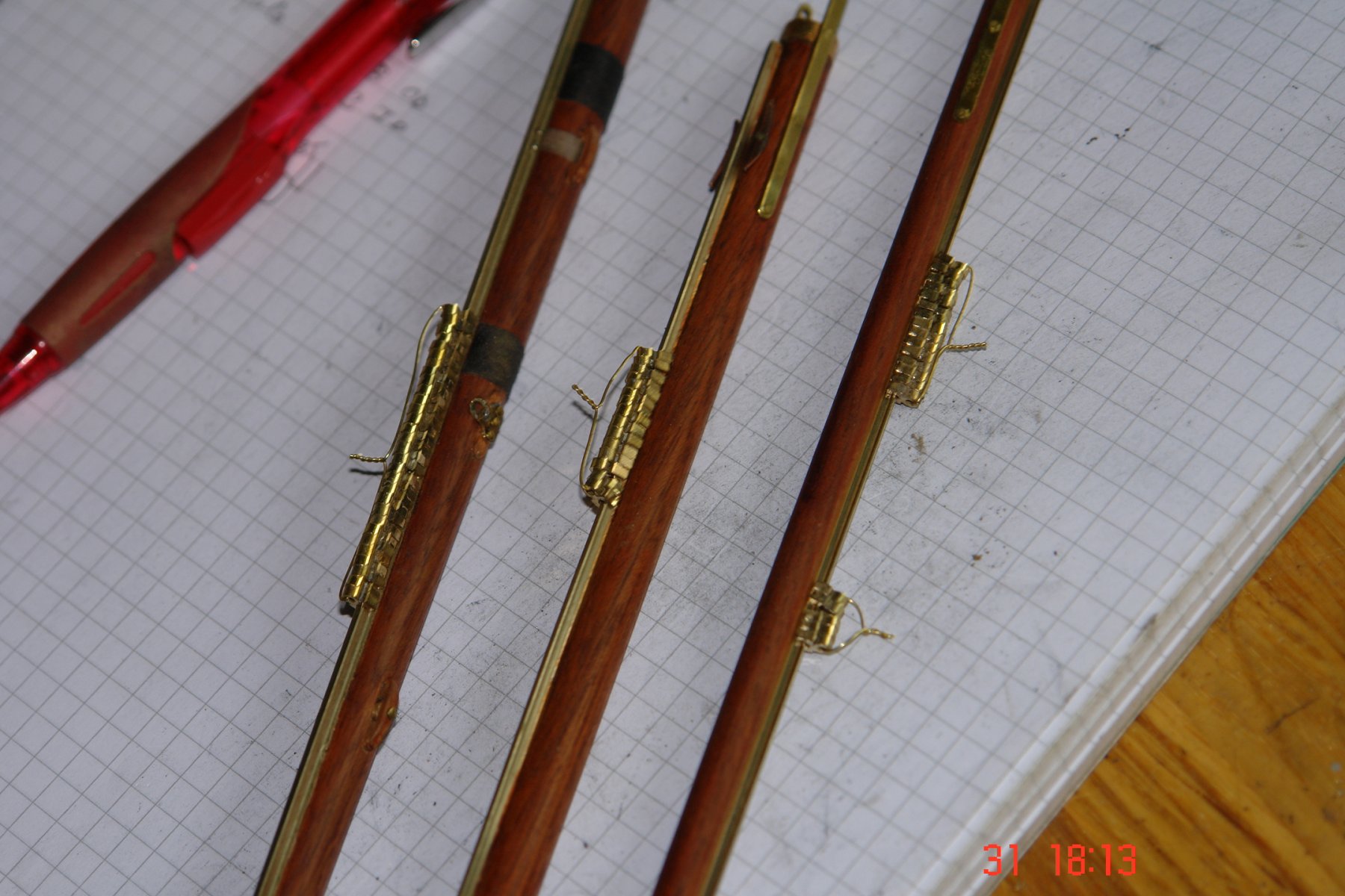
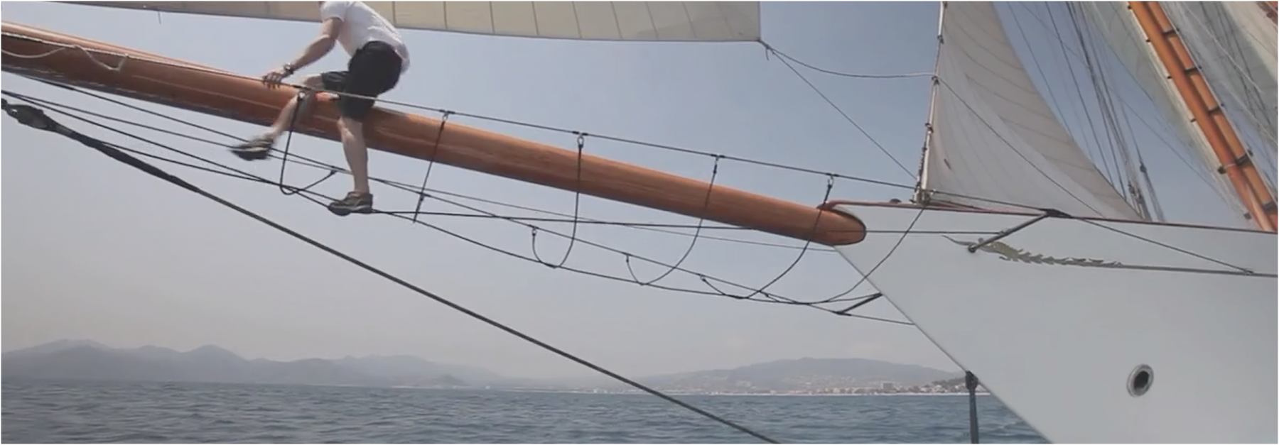
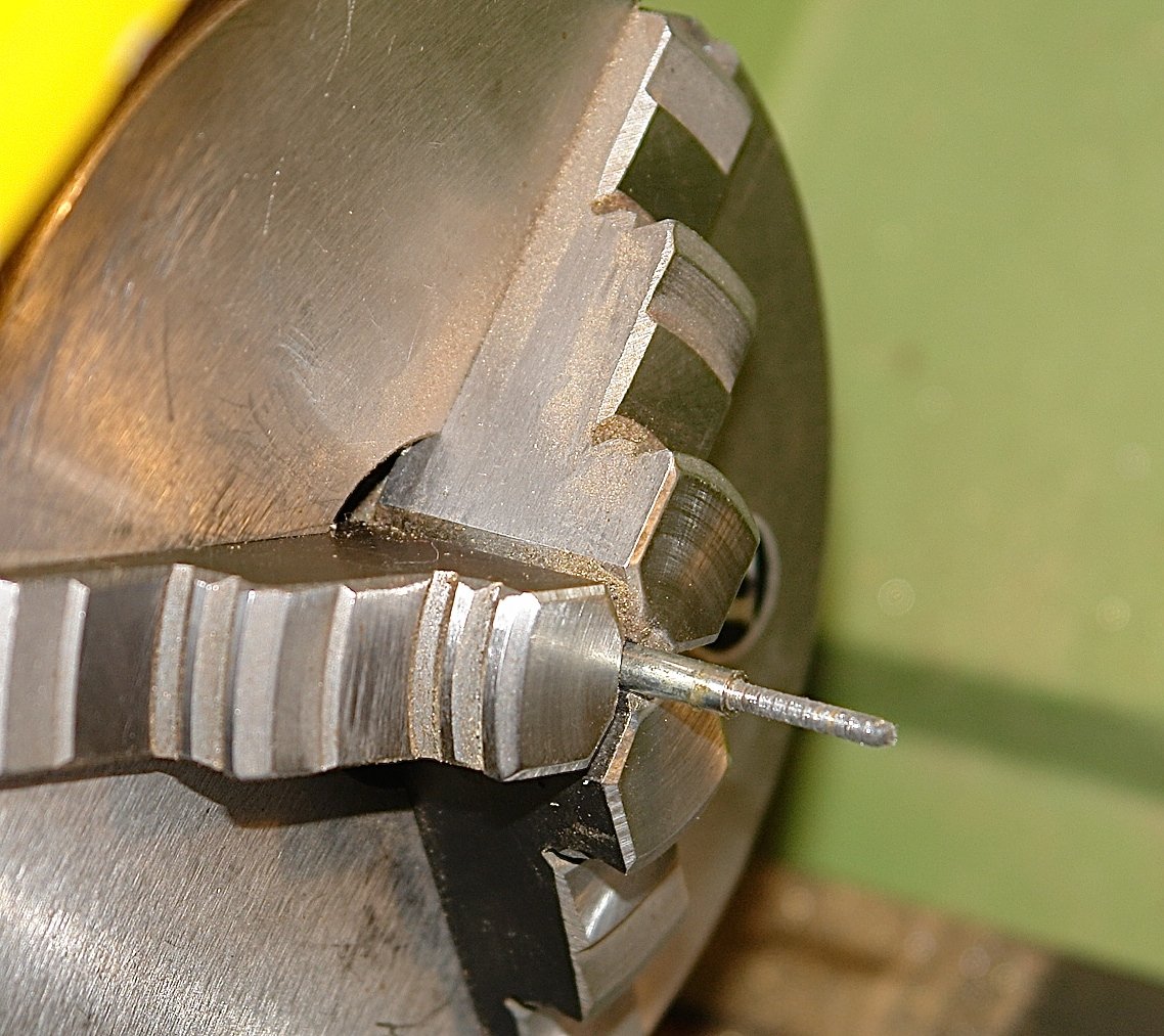
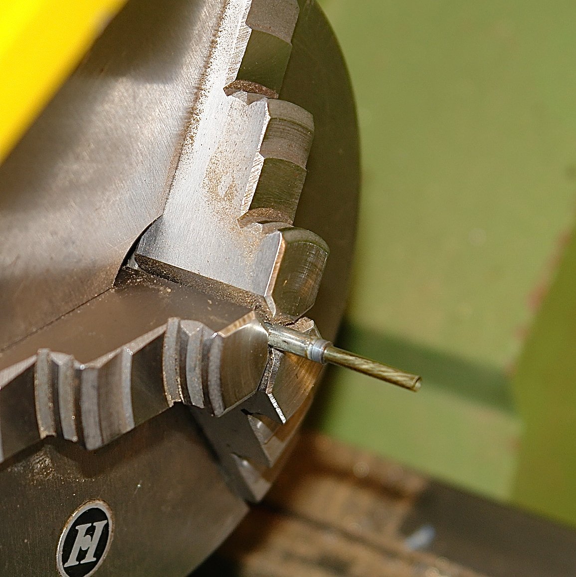
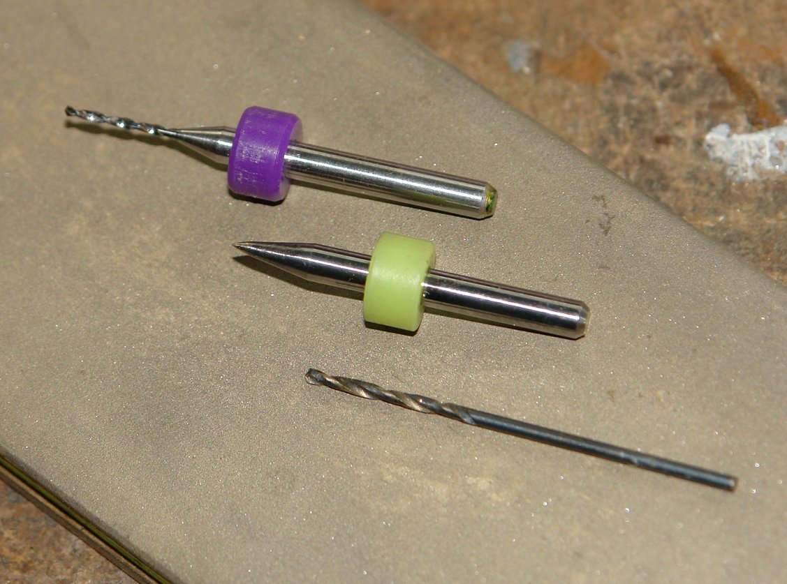
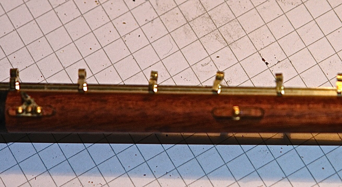
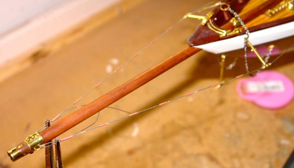
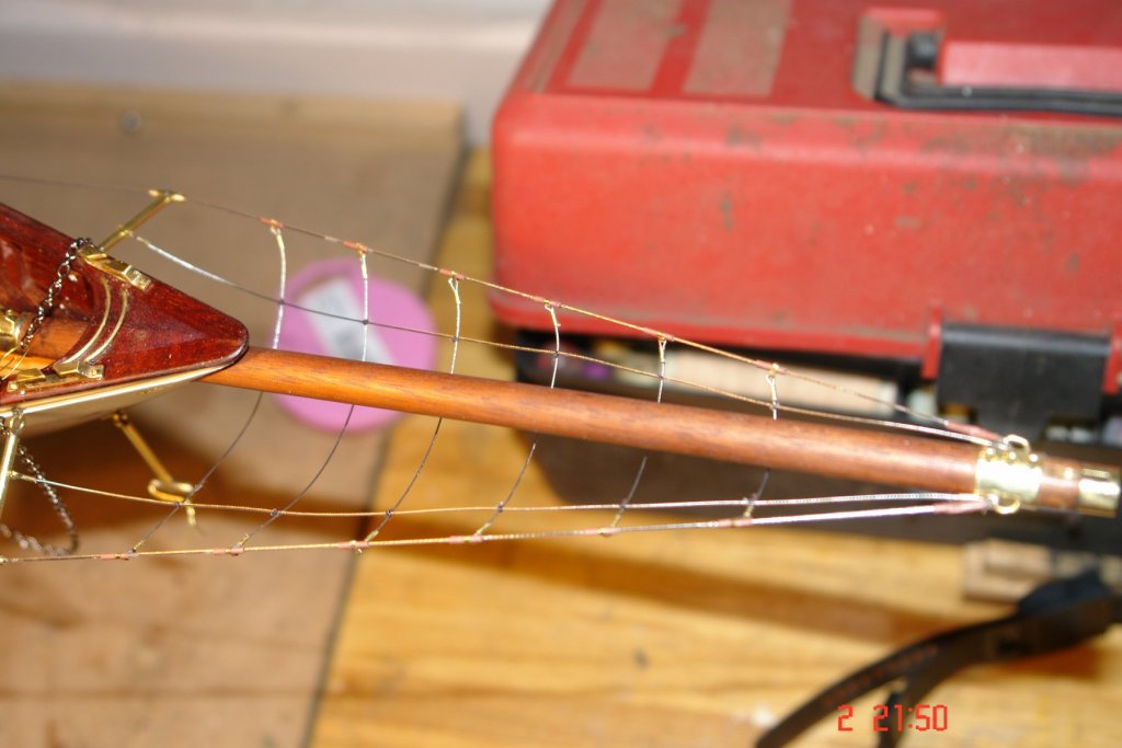
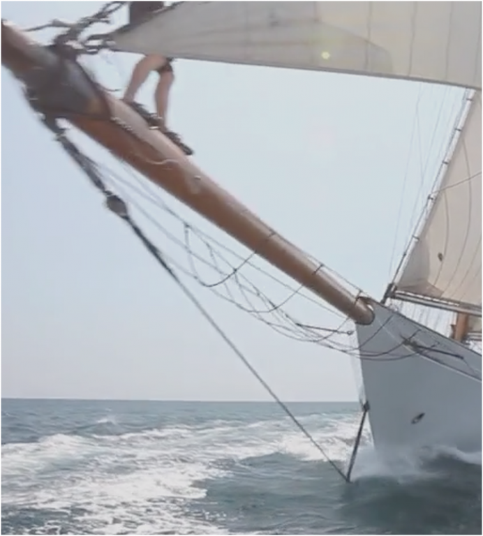
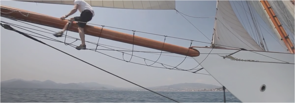
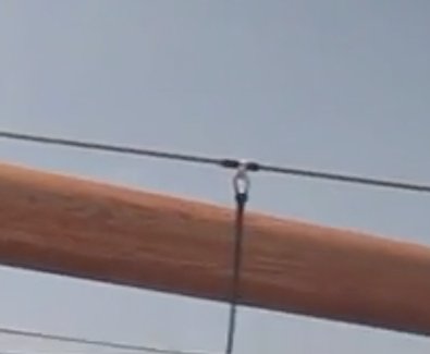
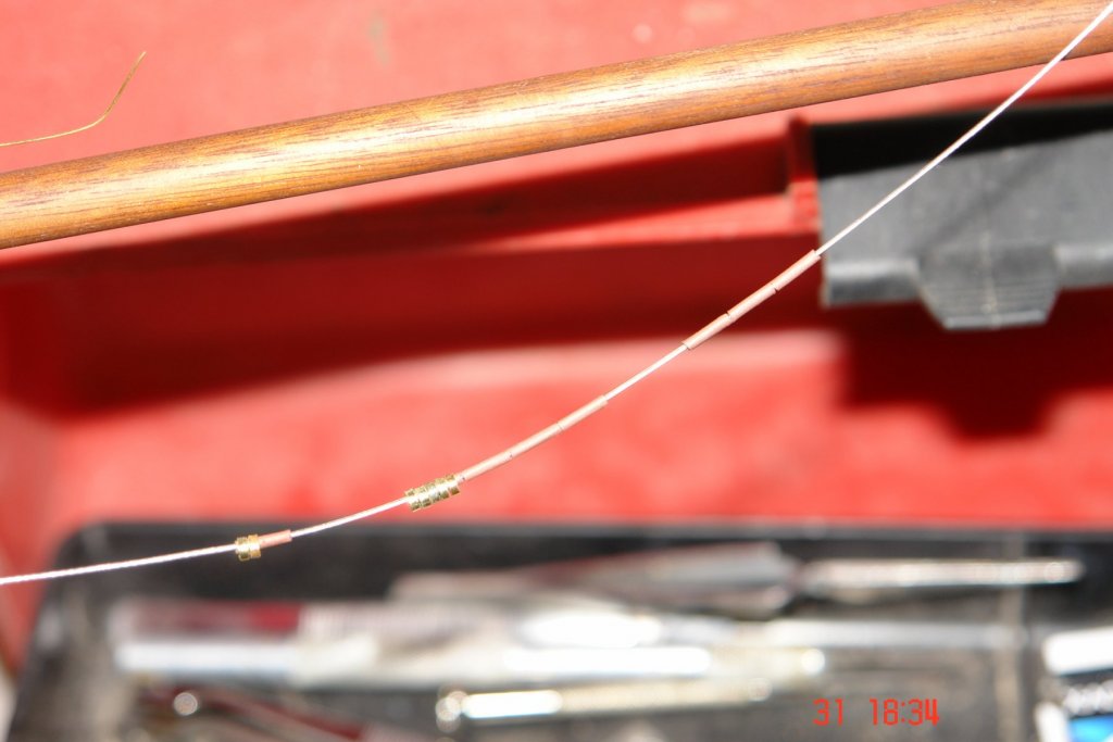
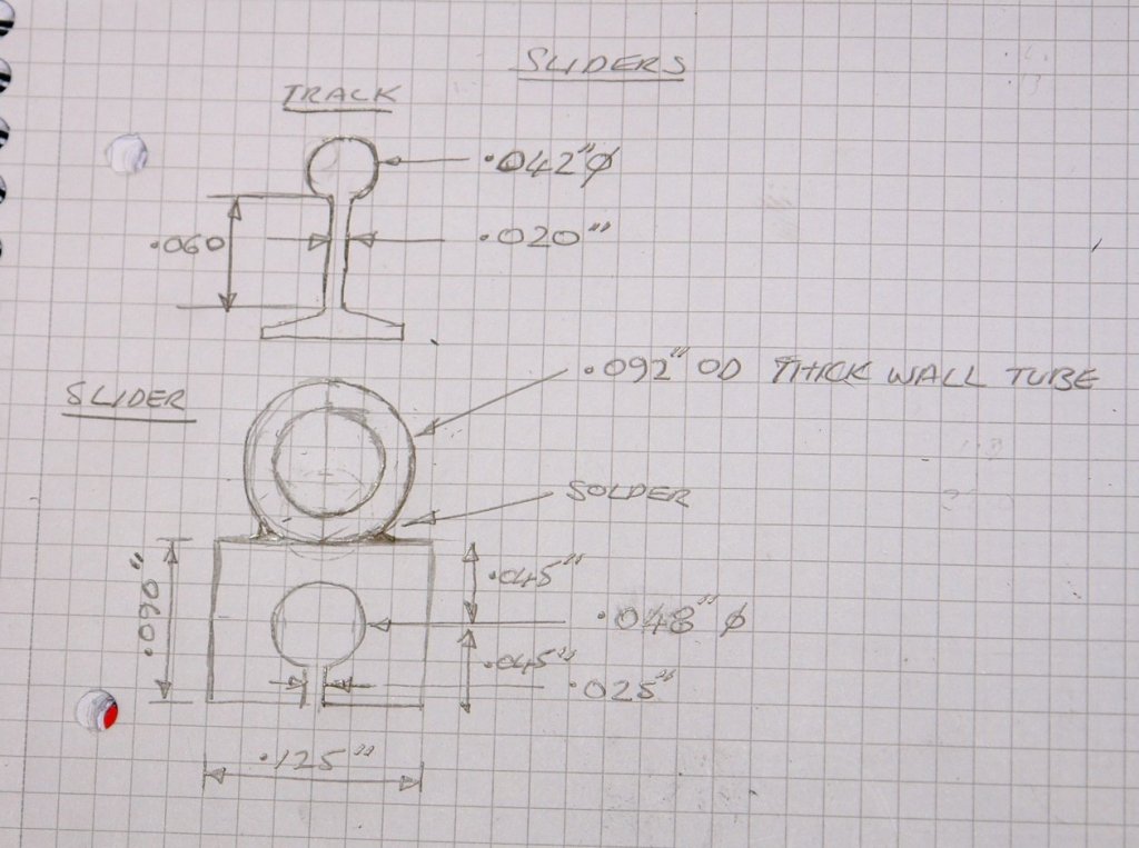
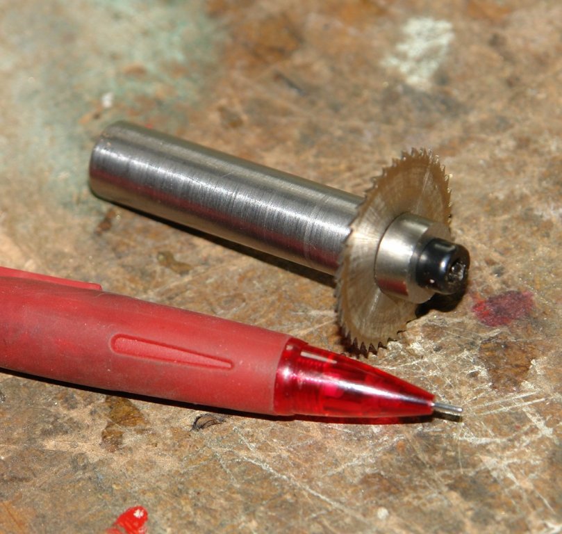
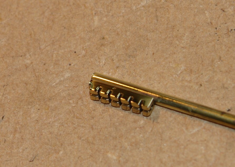
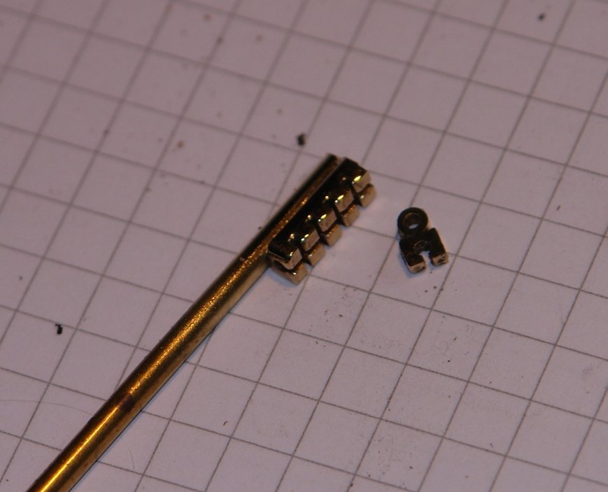
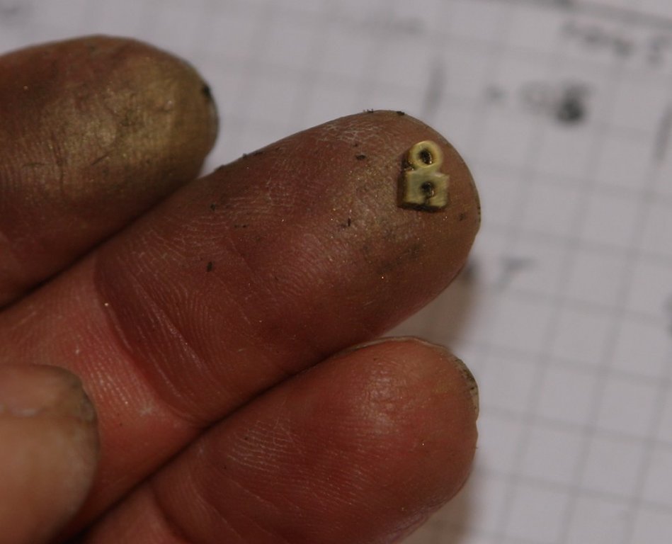
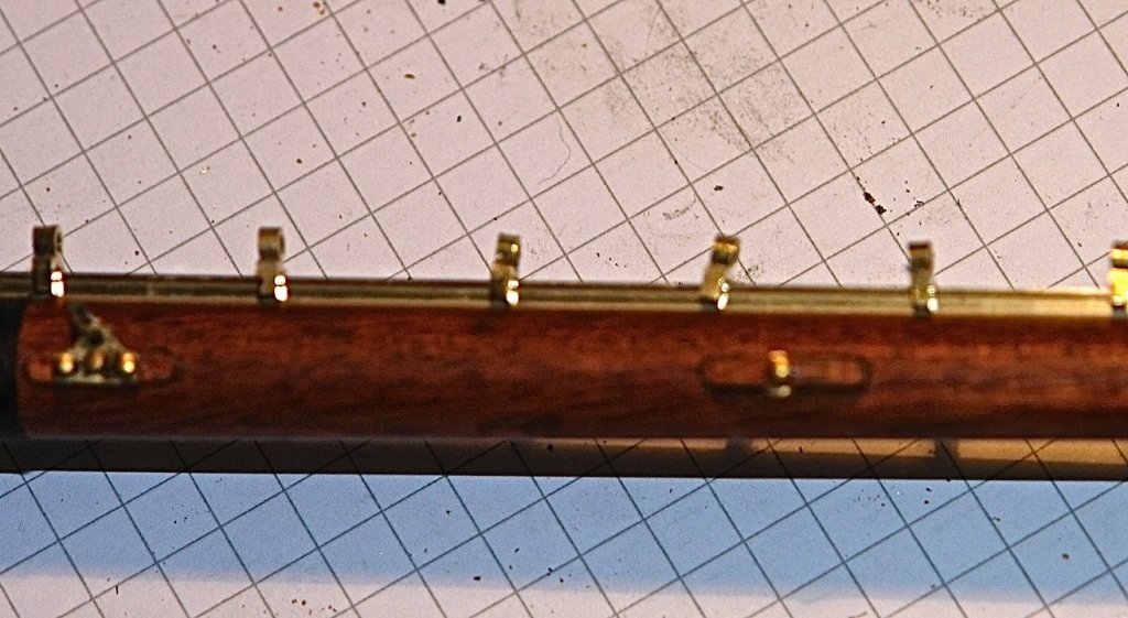
Herask / Druxey, Thank you for visiting and your supportive comments. Also thanks to all of you who left likes or just paid a visit. Well now for a fairly boring update - but the good news is that all 60 sliders are done plus 5 spares - for floor fodder. The sliders are currently stored on the tracks awaiting a later foray into sail making. I was a bit brain dead by the last batch - staring at small parts with less than perfect eyes is quite a challenge these days. So to proceed I started thinking about the bowsprit rigging. The first job was to glue the bowsprit into the shoe. Id been avoiding this because something kept telling me I would regret it. Anyway its done and the worry about the mystery problem may come to pass. Probably the best place to start with the bowsprit rigging is to have a look at a few photos of the real thing. The bowsprit shrouds are going to be made of 7 strand stainless steel braided beading wire - .024" or a scale size of a little over 3/4 inch. On the shrouds are attachment points for the skimpy lines that crew member is traversing. No netting here for whimpy crew members. The detail shot of the attachment point in the shot below below isn't entirely clear but I think what its showing is a protective band on the stay onto which the attachment lug is mounted. I thought it would be nice to try and reproduce this so I did a bit of experimenting. I plan to make the lugs from thing hoops cut from tube. The tube is .092" od thin wall tube and the hoops are sliced off .050' wide - done on the lathe for accuracy / consistency. The jig / operation is fairly easily understood from the photos. The tube is held on the spigot with a spot of CA glue for the turning operation. The hoops are very skittish so I made a lot of spares. I only need 12 so I am into overkill. The binding on the shrouds is going to be made from .060" bore heat shrink tubing - brown to simulate leather. The next shots show the first attempts - I'm sure I will get better with a bit of practice. (I ordered a heat gun off the web for my next attempt - a match wasn't very effective). I also started to assemble the components on to the shrouds. All a bit small but it fills the time quite well.


-
Hello Mitbok Sorry I am so late finding this build. As you say, what a beautiful hull shape. The build quality is tremendous. l liked the process for the seat pillars, I will copy that some time. I see that the guard on the Byrnes saw is always in the up position. I wonder if anyone ever uses the saw with the guard down?
-
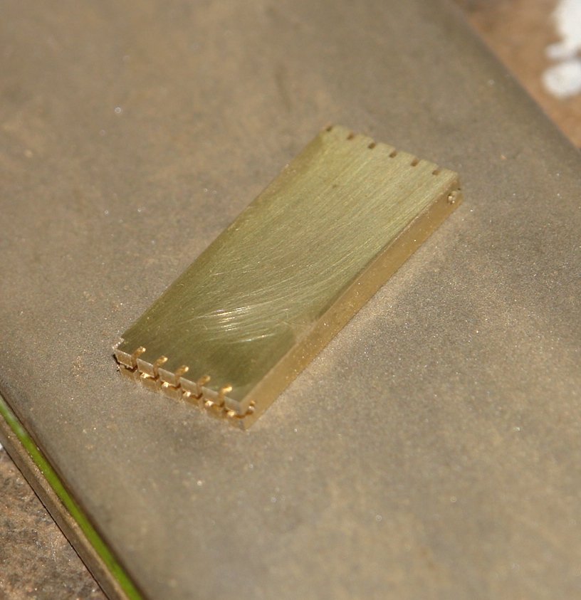
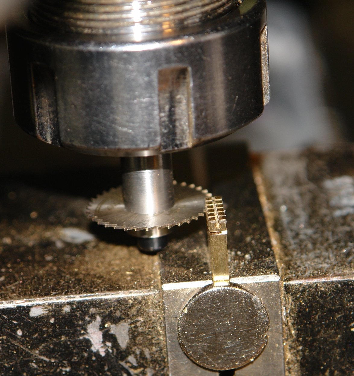
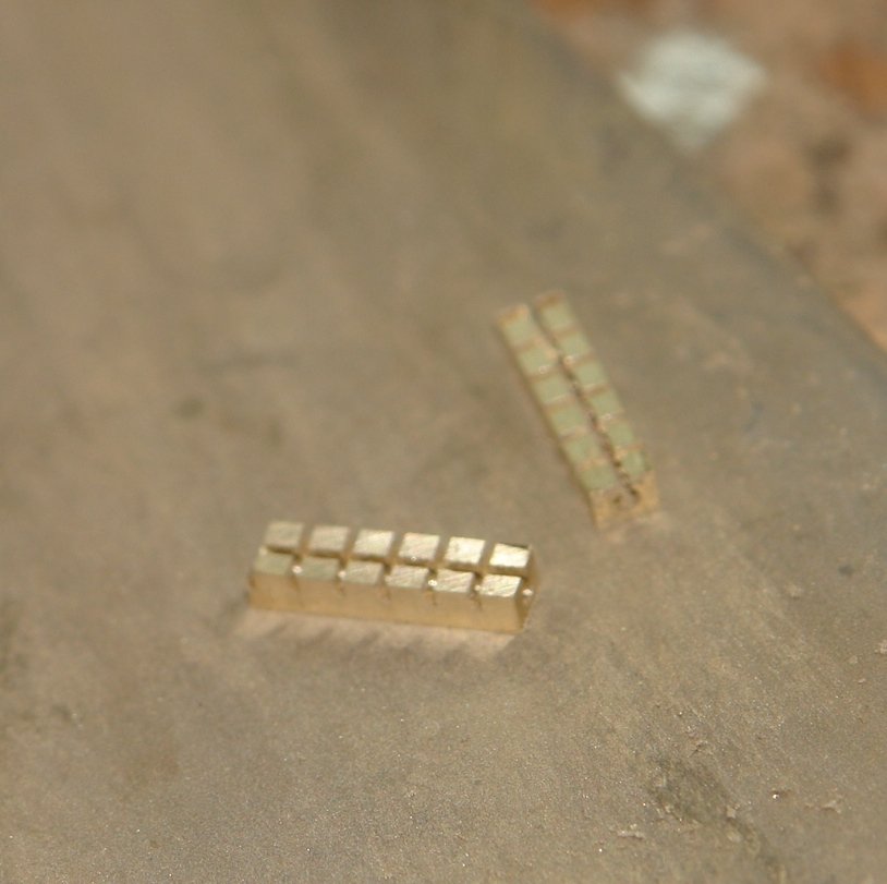
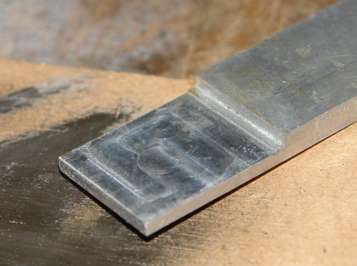
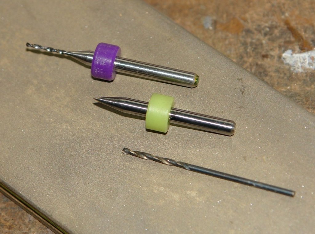
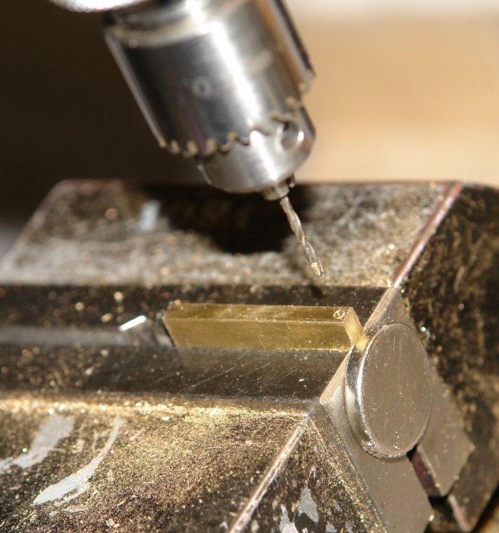
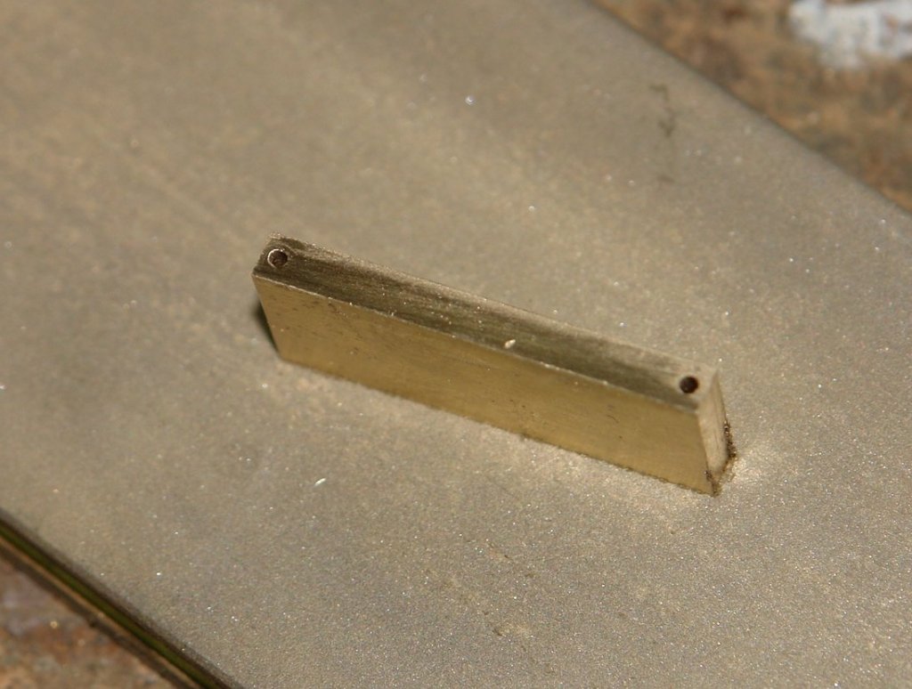
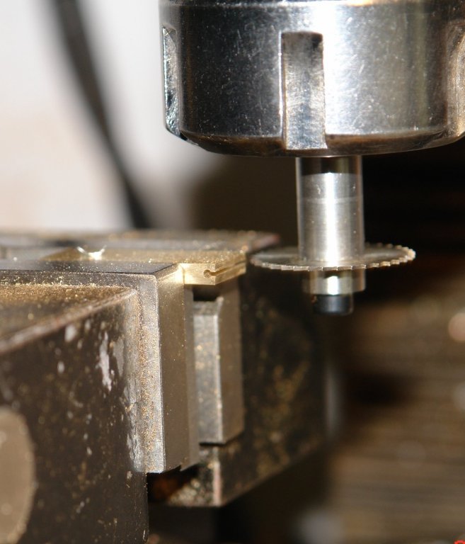
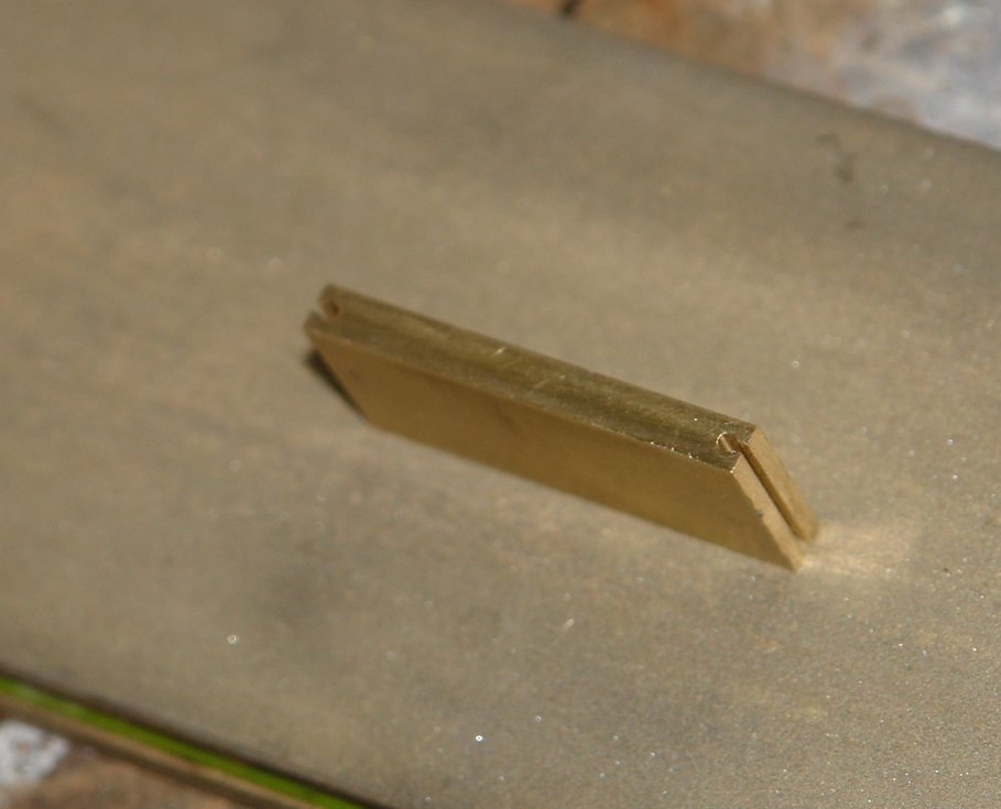
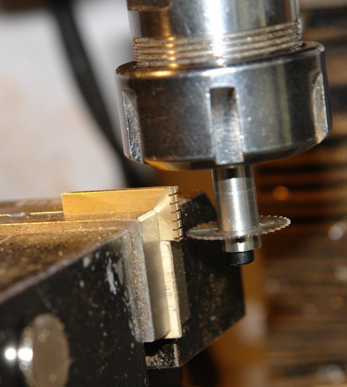
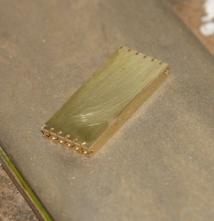
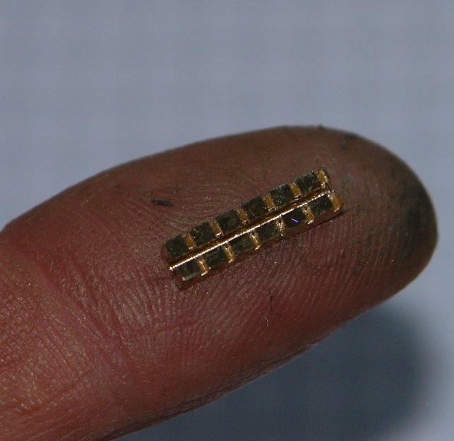
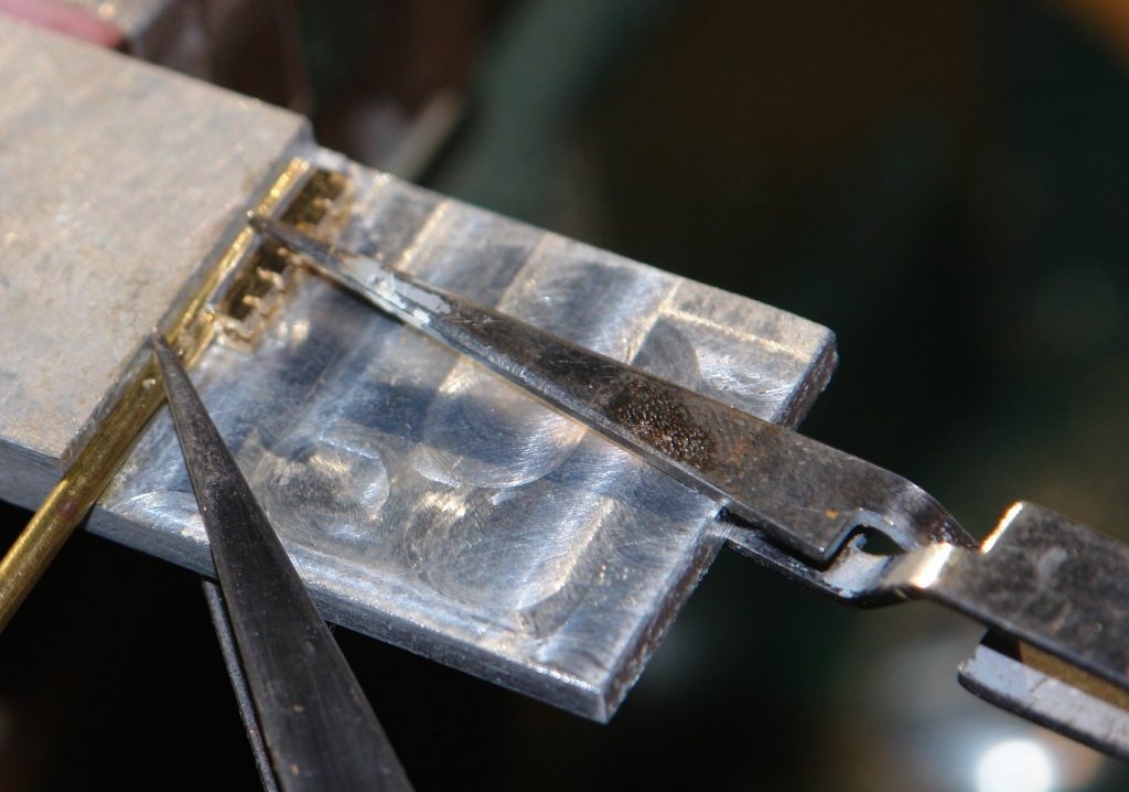
And so on with slider production - 59 to go. The sliders have to be sized to fit the track (00 gauge) previously fitted to the main, fore and staysail booms. This meant a design as per the following sketch. I decided the best starting point was .125" x .500" brass bar, this would allow me to make 6 sliders per batch. The first operation was to drill (on the mill) the .048" slider hole across the .500" width of the bar. I use a broken drill ground to a point to centre spot the hole and follow up with a .040 drill followed by the final size .048" drill. This in my experience is the best way to get the hole to start accurately and run true. I made 2 batches of 6 by working on both ends of the bar. The next operation was to slot through to the hole using a .022 miniature slitting saw held in a arbour I made for the job. Slight run out on the saw meant that it cut a .025 slot. Accurate centring of the slot was critical because any offset between the slot and the hole meant that it would not slide (I know because I did it). At this stage I did a trial check that the bar slid nicely on the track. I now did a series of cuts across the 0.125" width of the bar to divide the edge into .060" wide segments. These cuts were only part way through because I wanted the assembly to remain together for later soldering. The 2 ends were then sliced off .090" thick to make a "chocolate bar". I had made up a simple aluminium jig to assist soldering. The jig has a small step (just visible in front of the shoulder) which locates the tube relative to the chocolate bar so that once assembled the two parts are aligned on the centre line. I used aluminium to avoid the possibility of the sliders attaching to it during the soldering operation. The parts were placed on the jig and held with spring to close tweezers while soldering with a butane torch. After a bit of polishing the slider segments were cut off using a razor saw. To make 6 takes about an hour - so 60 is 10 hours (across a few days).


- 882 replies
-
- 17
-
-
RussR How about sticking it to a longer piece of sacrificial timber using double sided tape. Then cut it on a chop saw or table saw using a very thin slitting saw blade while holding the sacrificial timber. Alternatively if you don't have power tools cut it with a razor saw and mitre block.
-
Hello Hamilton. It will be interesting to hear how you coped with getting the plank edges to line up as you progressed with the planking. In builds such as this where the distances between the frames are relatively large compared with the thickness of the planks I find that the planks want to "flatten" out mid way between the frames and that this makes maintaining alignment of all the plank edges a bit problematical. That said many builders seem to cope with the problem very well. Any learning points you want to impart will be most interesting. The build is coming along very well.
-
Jim The first ship plans I bought were for HMS Hood when a 16 year old back in 1969. Interesting to note that when I bought the plans she had been gone for 28 years whereas I have owned them for 48 years. My how time flies. I'm looking forward to seeing how this develops.
-
Thanks Richard, you are too kind. I too am having a few days away but once back I'll do a bit of detail on my method, trials and tribulations in making the sliders. Then it will be on to masts and standing rigging. I have been doing a bit of internet surfing on suitable materials for sail cloth. Altair has a "modern" set of sails so I need something to simulate these. I'm stilll undecided so suggestions are welcome.
-
She is coming along really well.