KeithAug
-
Posts
3,986 -
Joined
-
Last visited
Content Type
Profiles
Forums
Gallery
Events
Everything posted by KeithAug
-
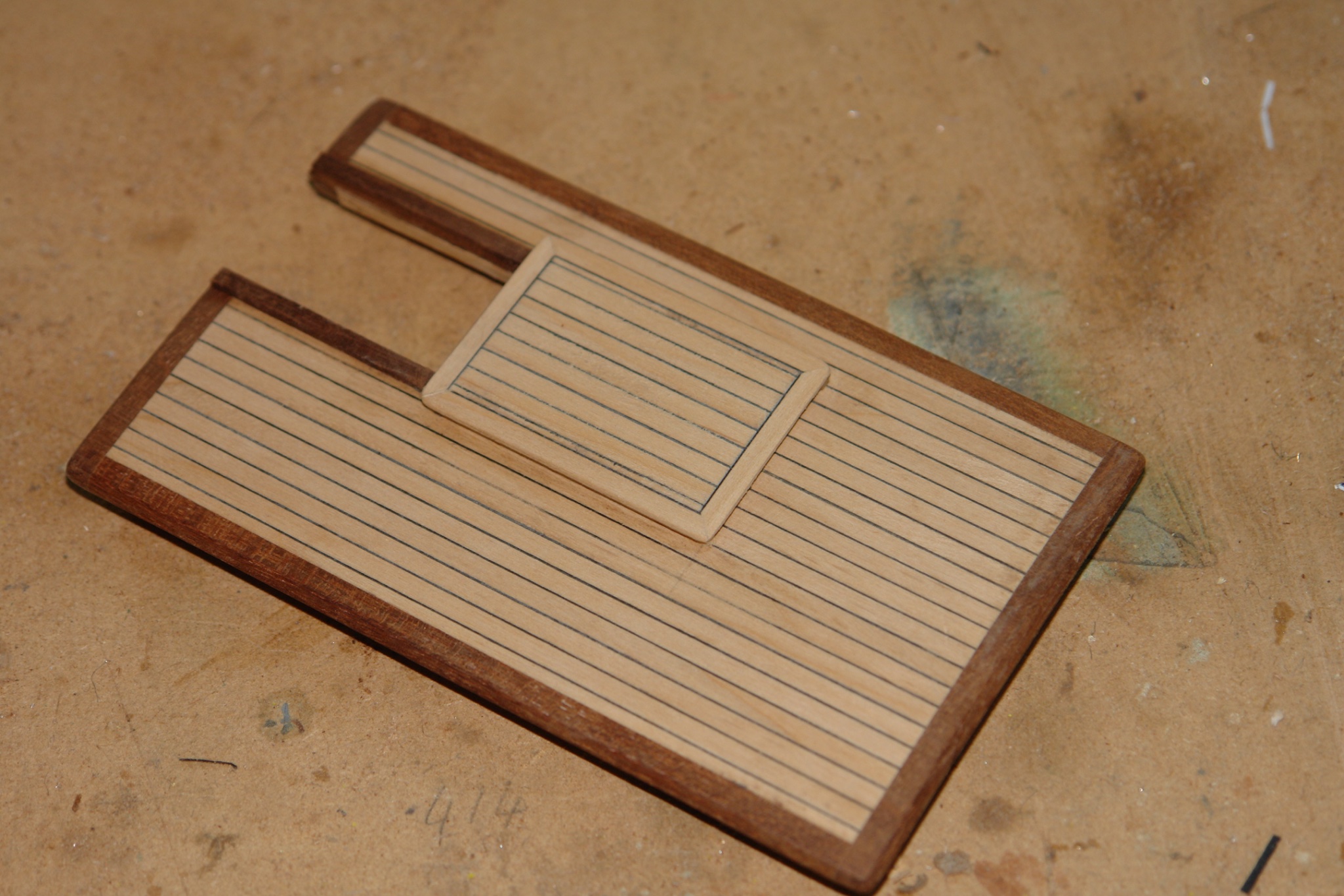
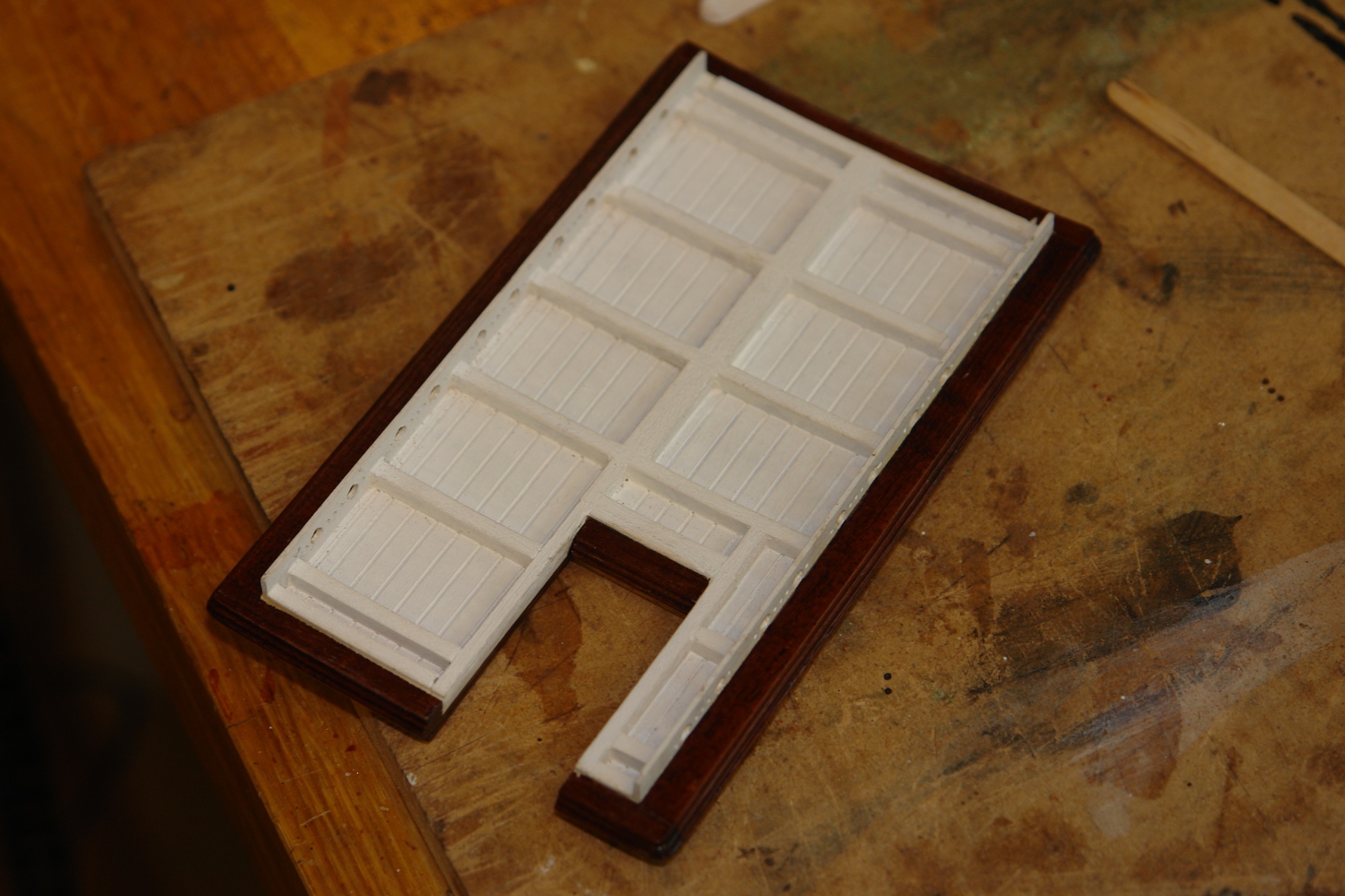
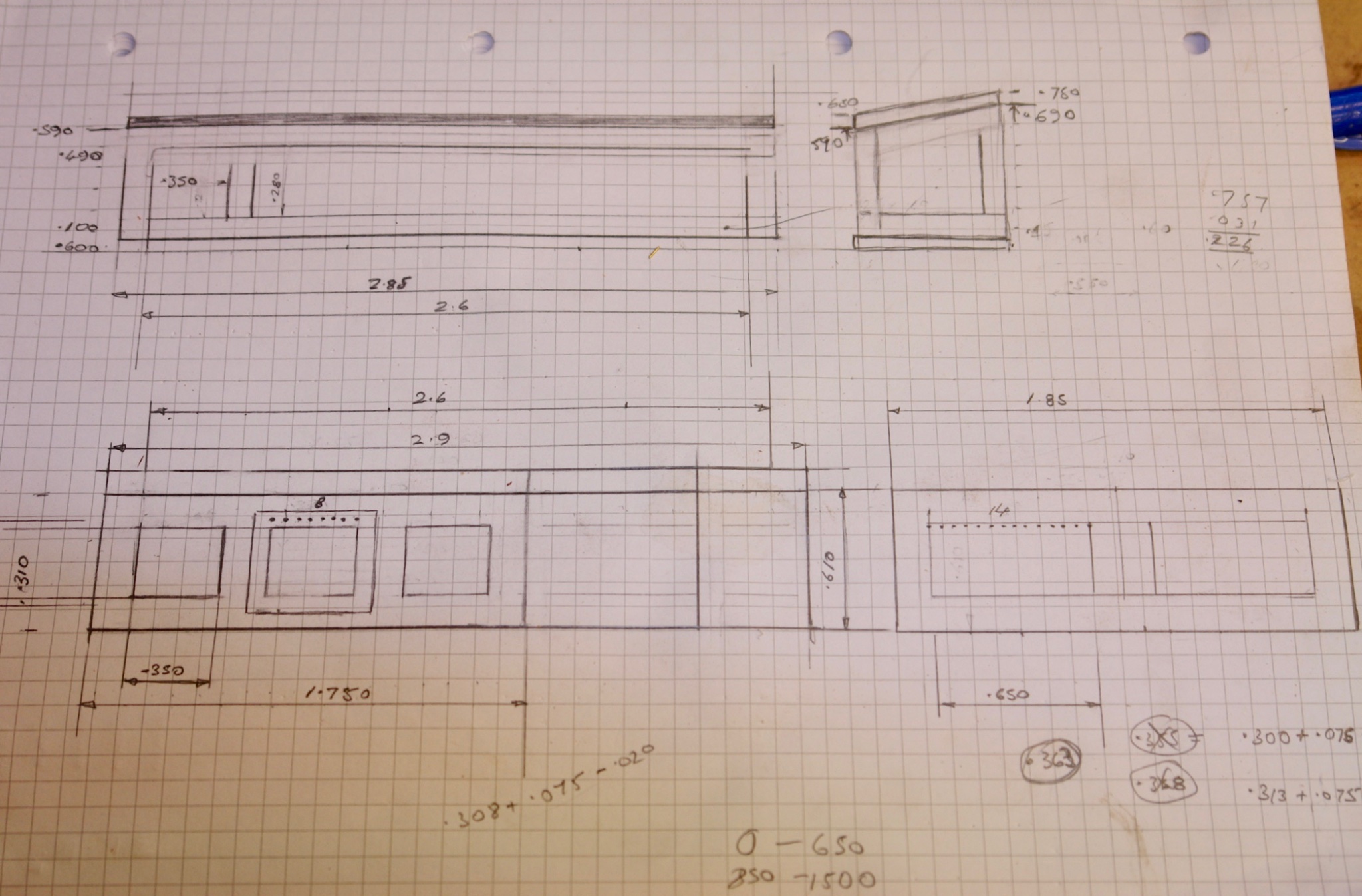
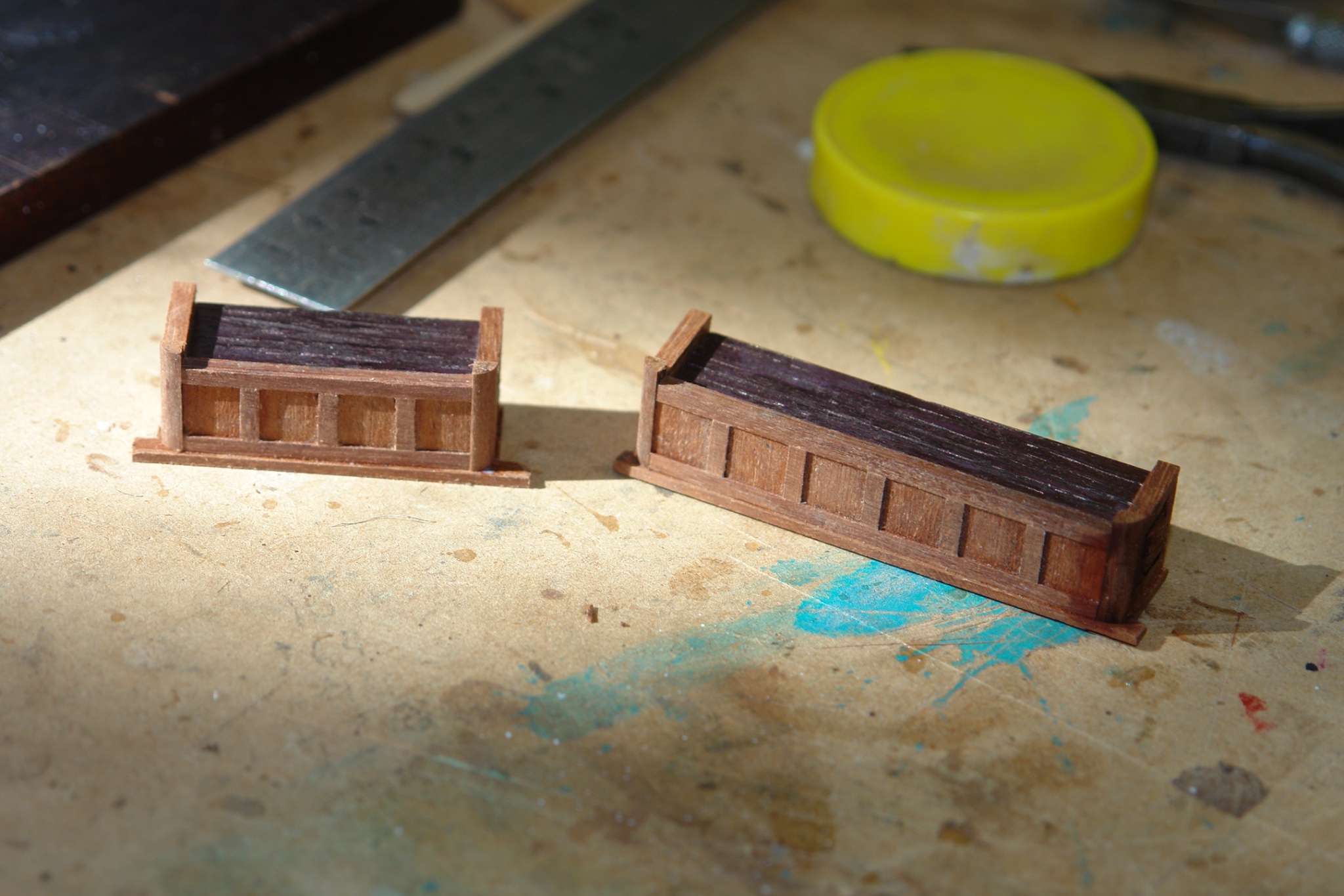
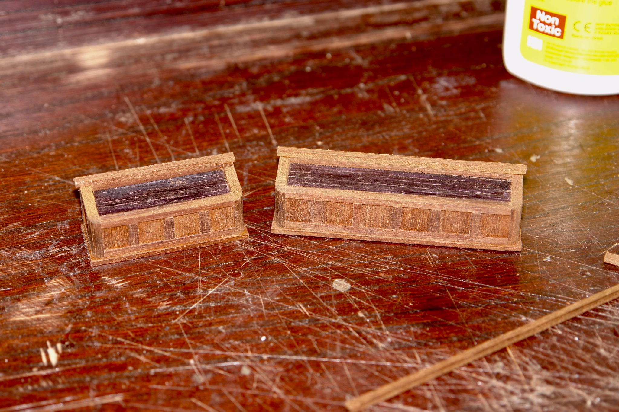
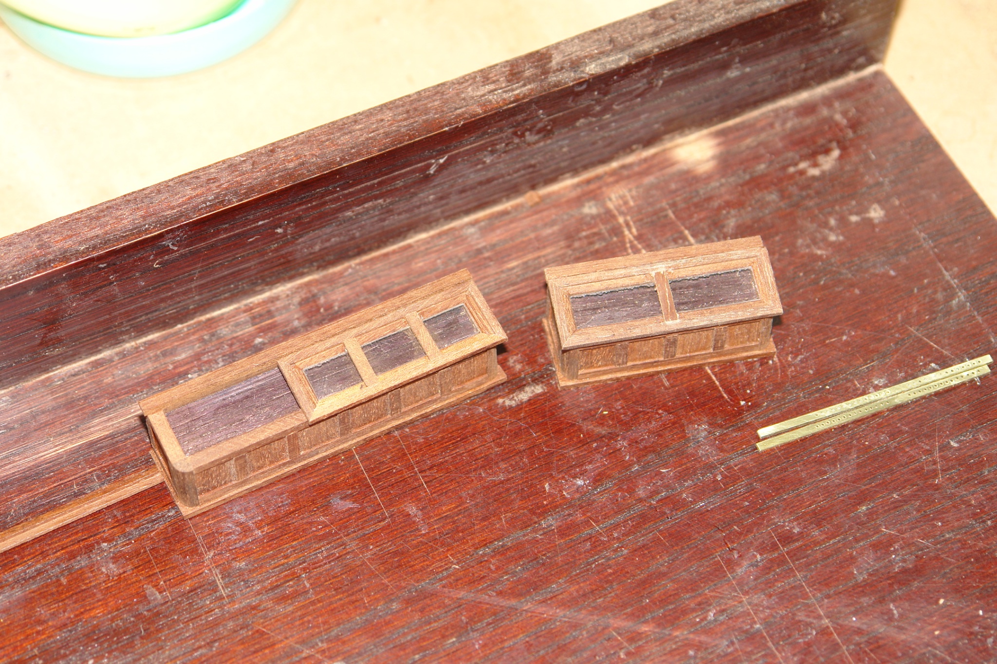
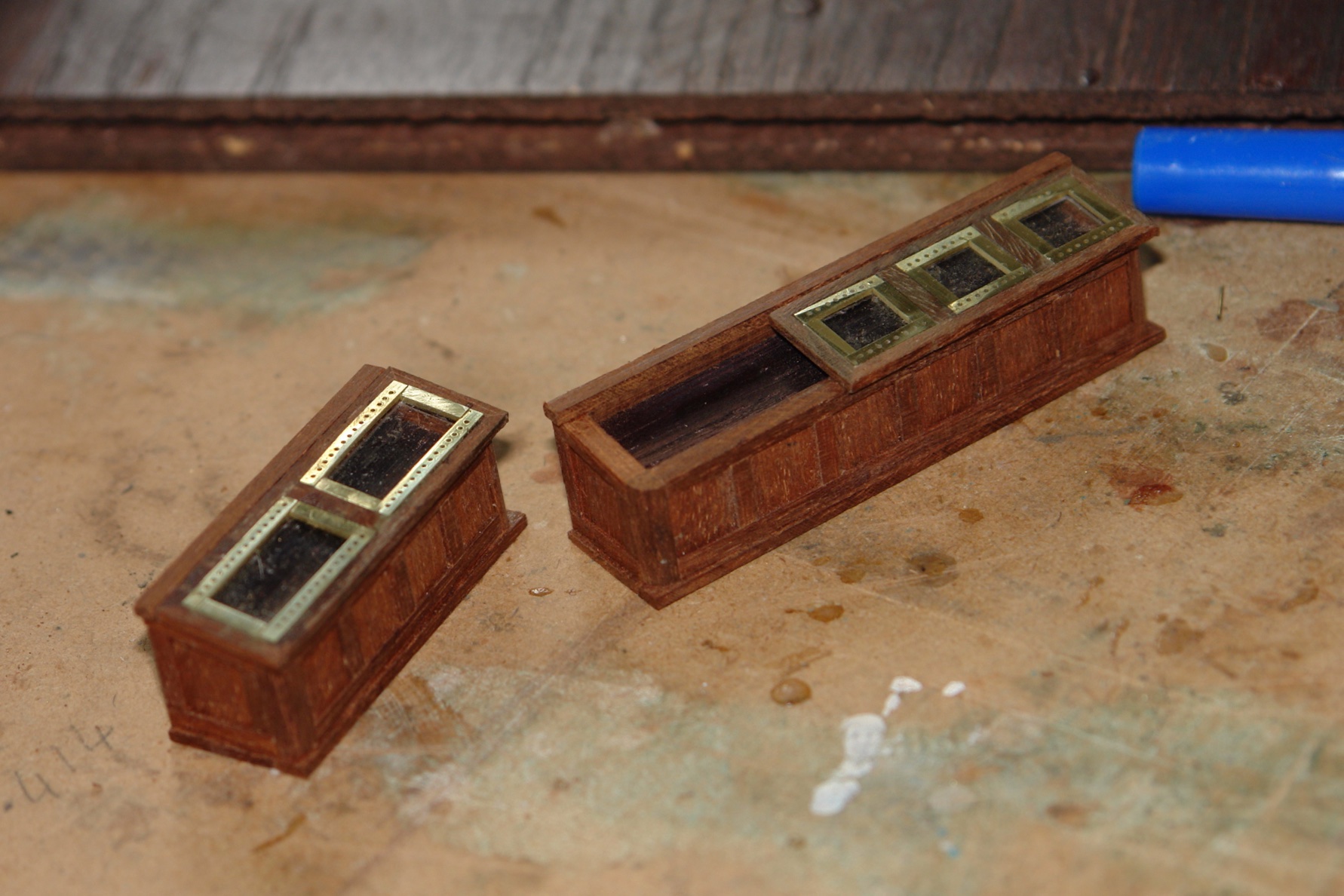
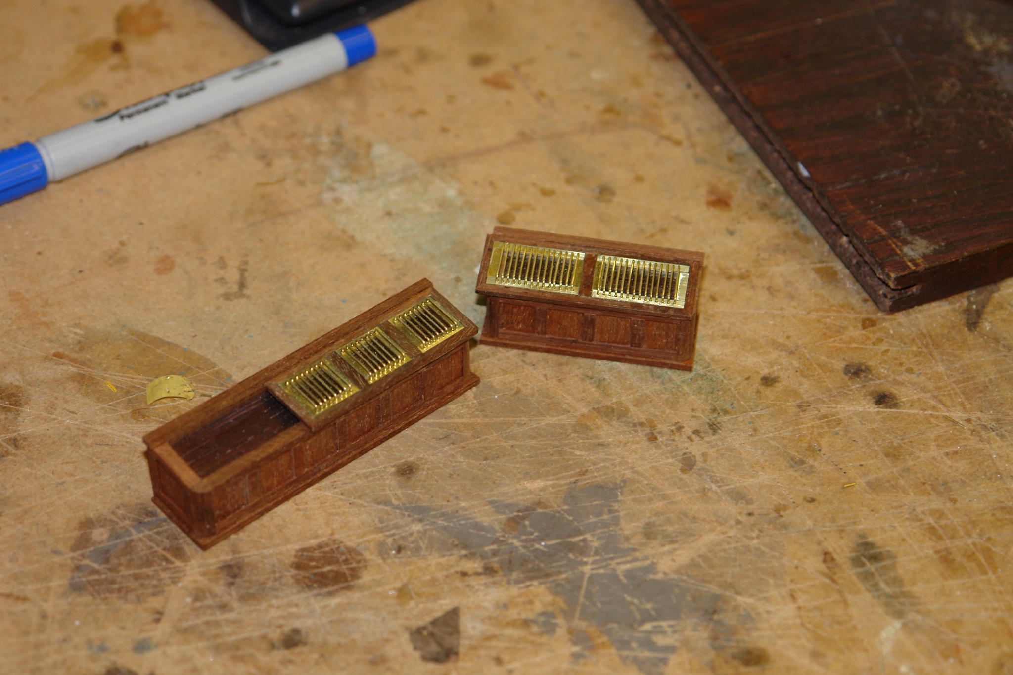
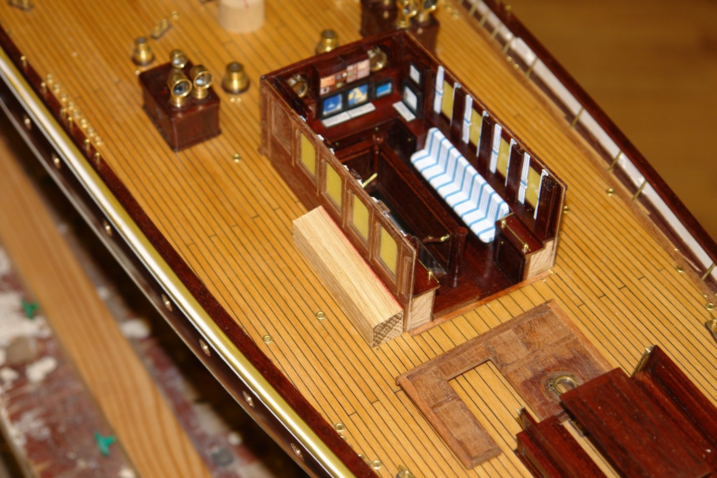
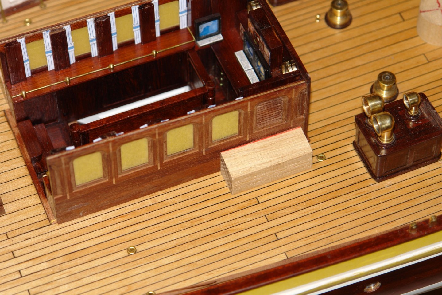
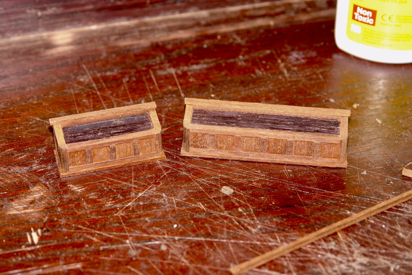
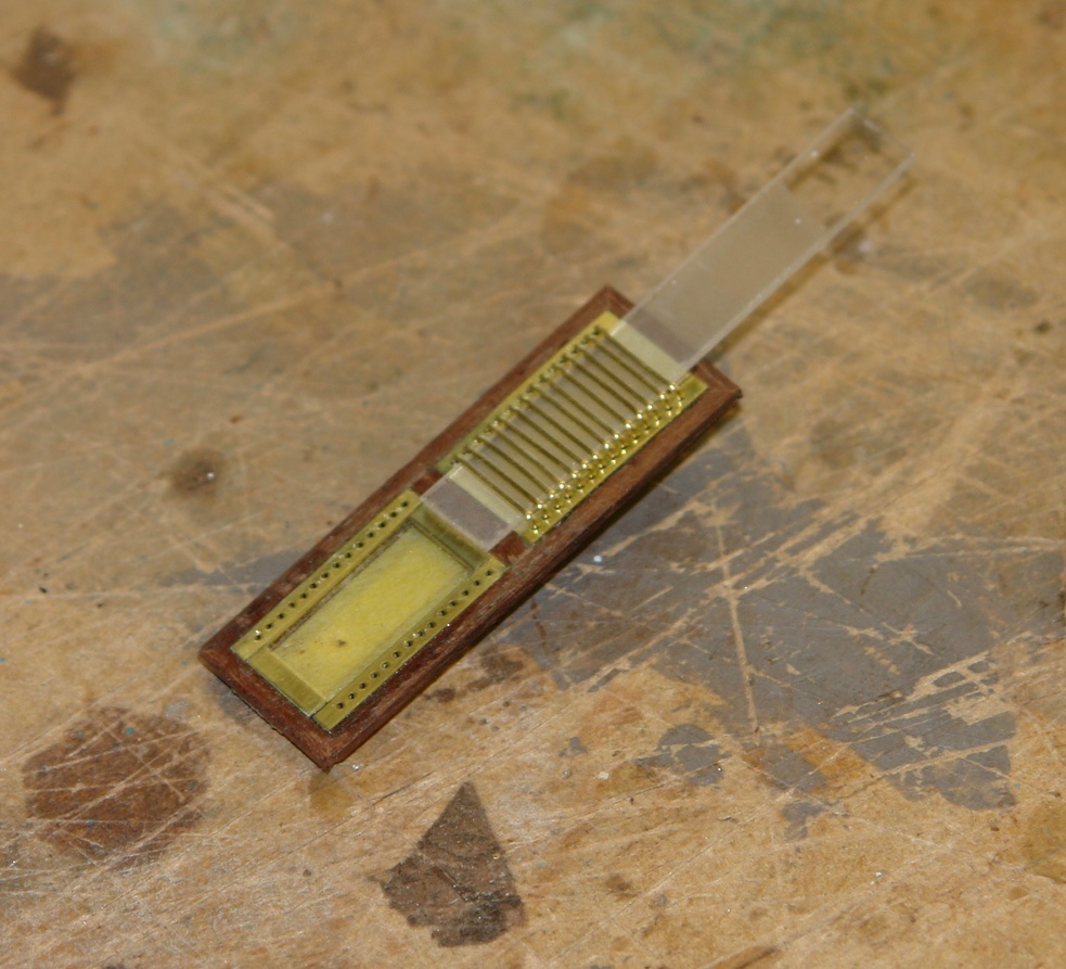
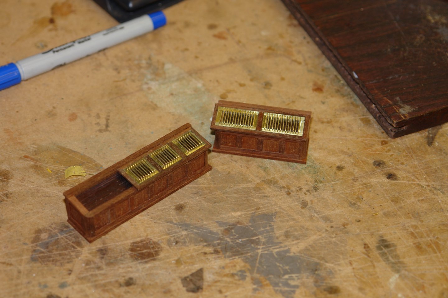
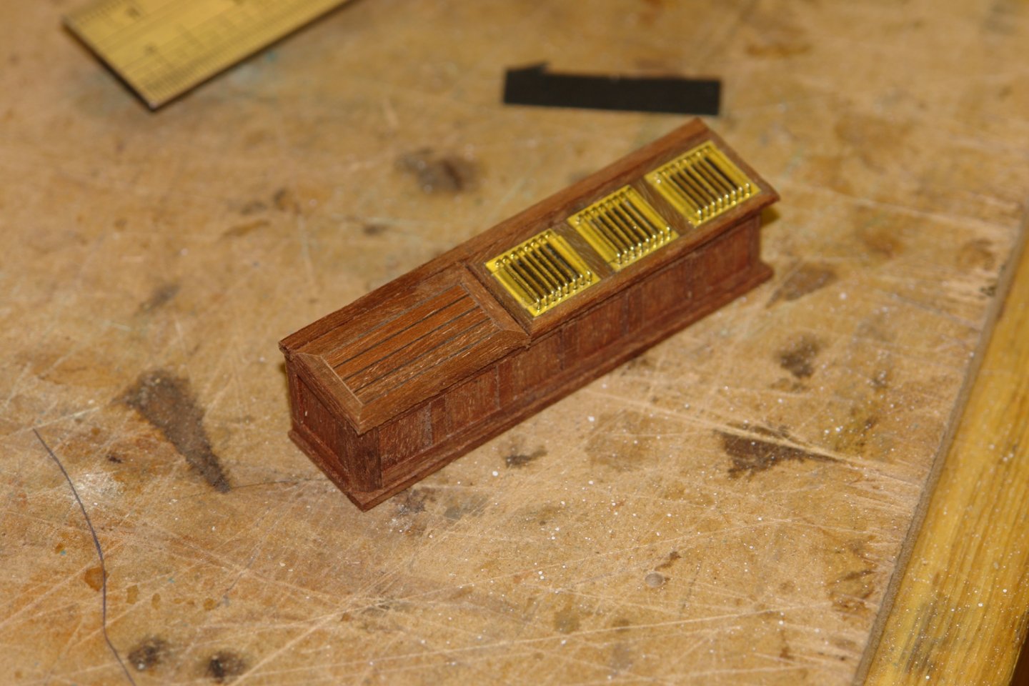
 Thank you Richard and Gary and thanks to everyone for the likes. Well here we go again, shortly to be locked up for another month - good job we have a dog to get us out for woodland walks. The hatch was finished by creating a framed surround and then glueing it in place in the open position. I could have made it slide but the previous one (on Altair) quickly ceased up. It didn't therefore seem worthwhile. The underside was then given a quick once over with wire wool before being masked and painted with 4 coats of white acrylic paint. For no particular reason I then moved on to the "wings" on either side of the deckhouse. The box structure are variously photographed with planked tops and with protected skylights. As previously I went with the skylight version. Having made similar structures before I didn't need a very detailed sketch. The port wing is longest at 2.9 inches wile the starboard structure is only 1.85" long. Both are .650" high by .710" wide. As previous I started with oak cores. These were clad with mahogany frames and panels. The skylight frames were then made and glazed and brass strips were cut to take the protective bars. The brass strips were drilled and mounted prior to installing the bars. The bars were then installed. Finally the planked section was made to cover the exposed section of the longer wing. I haven't glued the tops on yet - a job for tomorrow.
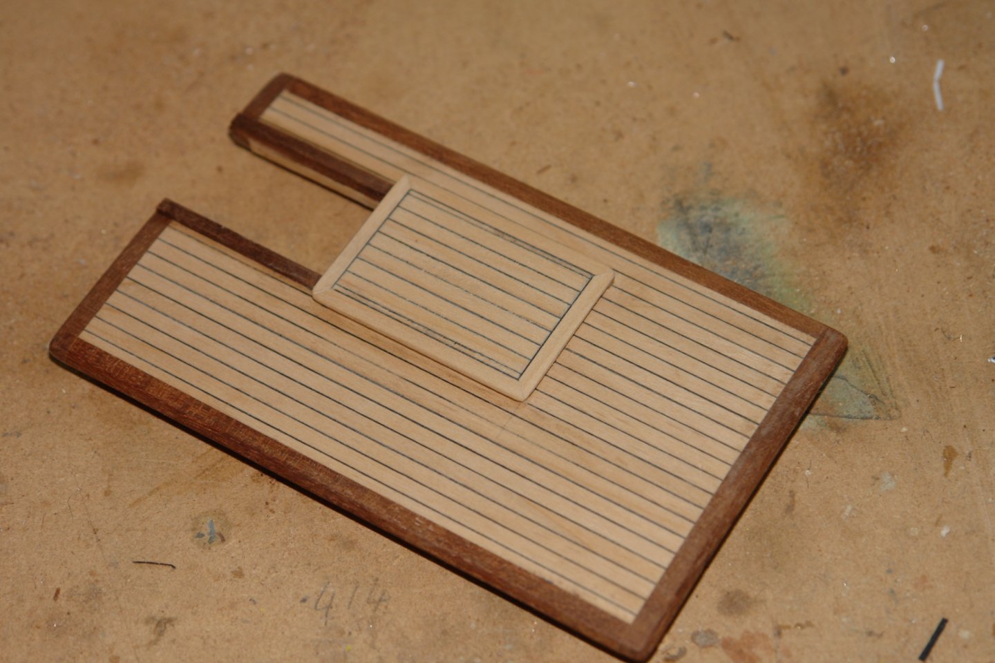


-
Richard - pumps very nicely made, excellent machining of such small parts.
-
Valerie, excellent shackle - and the extra bit of explanation was yer helpful. What diameter wire did you use?
-
Your builds pass too quickly Javier. This one is progressing at warp speed.
- 15 replies
-
- 1
-

-
- fishing boat
- small boat
- (and 1 more)
-
Thank you Allan, I always seem to forget that styrene is an option. Boring out rod is pretty straight forward, let me know if you need any advice.......... but as you say the original is wood then wood is A good way to go.
-
Allan, Anchors can be quite tricky things to make. The photo isn't very revealing but it would be good to know your process for making it. Also the mast hoops look good but what was your rationale for making them out of holly rather than metal.
-
Exactly so Michael. Eberhard - Thank you, but its not something you are going to find very useful at your preferred build scale.
-
Hello Kevin. Thank you for the compliment. I guess you were jesting but I think you can do it on the MF70. Use 2x24" planks of MDF attach one to the table, hanging out over the end of the bed. Put the pivot at the off table end and then mount the top MDF plank on the pivot. Problem solving is such fun.
-
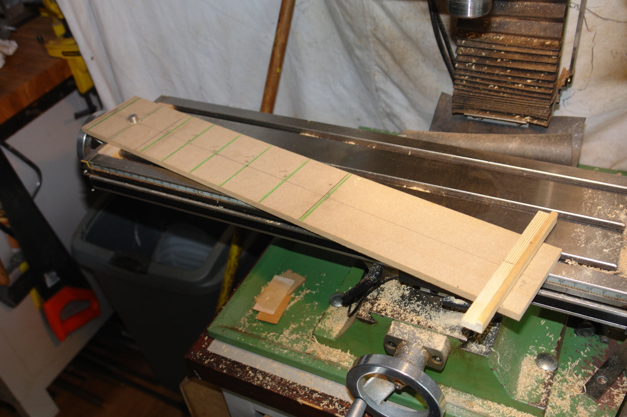
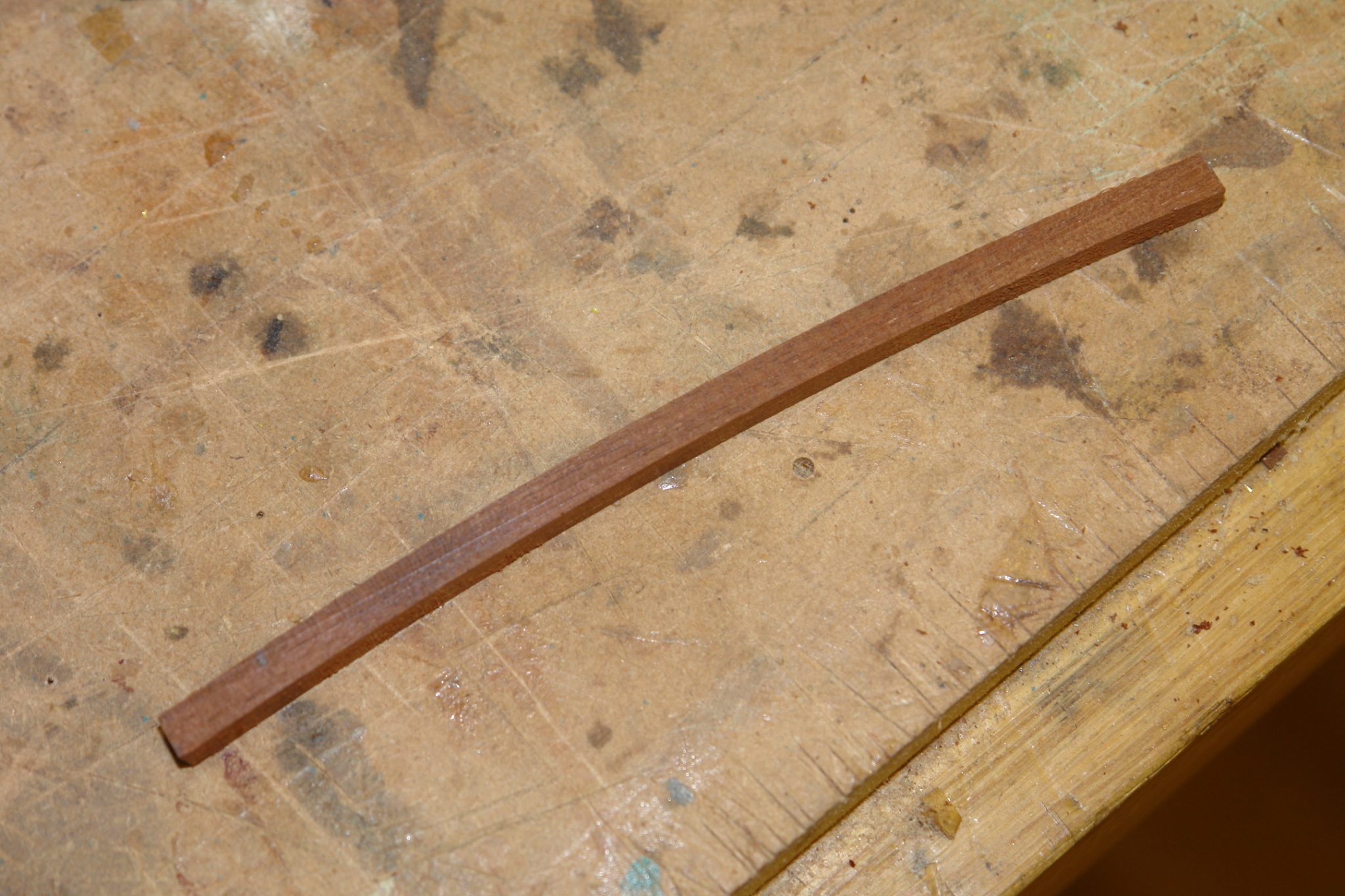
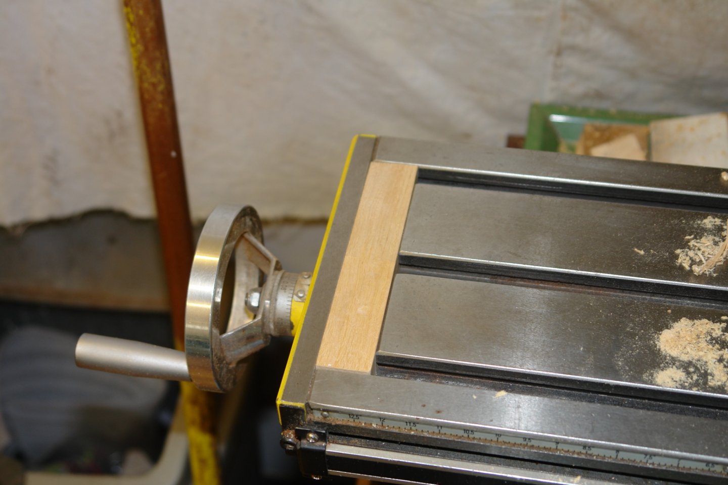
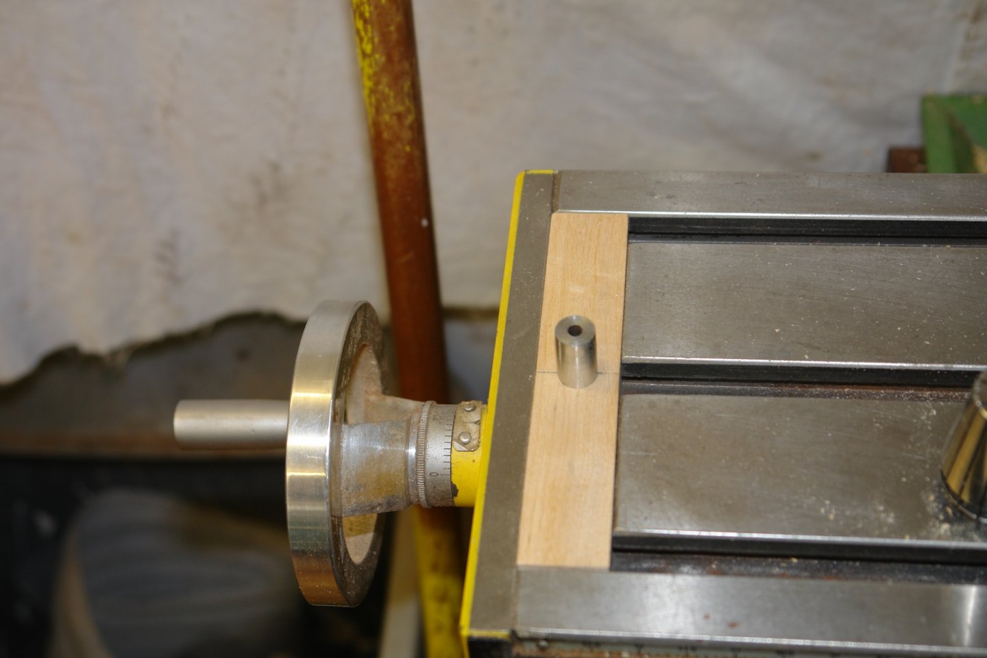
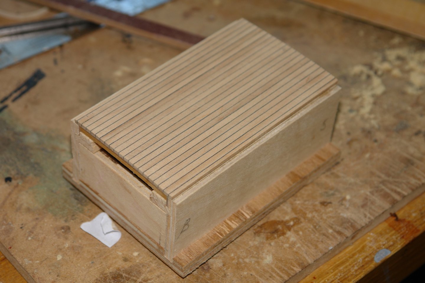
Hi Michael, thank you for your comments. I only ever part off on manual feed so doing it slowly was fairly easy. I find soft solder is remarkably strong for jobs of this type, it rarely seems to come apart during machining. I did however make sure the parting tool (which was only .025" wide) was very sharp. Pat - I look at many models on this site with admiration, everyone seems to have something that they excel at. And so to cutting the roof end mouldings. I checked the curvature against a set of radius templates that I downloaded from the web. The radius required turned out to be 22". I improvised a jig to cut this radius. I started by cutting a piece of wood to be a snug fit in the end slot of the mill table. Into this I inserted a steel peg. A piece of MDF was then cut, one end with a hole to fit over the pivot pin and the other end with a "L" section cross piece onto which the mahogany stock was mounted. The distance between the pin and the centre of the cross piece was 22". The mahogany was mounted with double sided tape and the curved beam was cut by progressively passing it backwards and forwards while feeding the end mill down. It didn't take long and the results were fine. I used the previously made scraper to form the profile before glueing the ends to the roof. The corners were then manually finished so the moulding shape wrapped around the corner. The cut out for the hatch was then removed and the hatch runners and side detail was then commenced. The hatch planking was built on the roof to get the correct curvature. Sellotape was laid on the roof to facilitate this operation.


-
PoulD - Early on I did toy with putting LED's inside the hull but I knew that after the first few months I would never turn them on again. Thank you for your kind comments about my craftsmanship, I keep trying but have a lot of room for improvement.
-
Druxey, Steve, John - thank you for the compliments, they keep me warm as the workshop starts to cool - only 9 weeks to Christmas.
-
Keith - You are right to suggest it won't be possible to see them so it is somewhat pointless....................... but of course I will.
-
Richard, might work but at 0.2" thick I think it would have some memory and would flex back to a larger curve. I could over bend but this might be a bit hit and miss. I have worked out a plan to machine the planks to the desired radius. I'll try it some time this week and report on my success or failure later this week.
-
Vaddoc This is also a good supplier of wood and usually cheaper than Cornwall. https://www.slecuk.com/ Nice work with the scroll saw, but glueing pattern on the reverse sounds very tricky. Good luck.
-
Simple rope making machine in Lego
KeithAug replied to Brinkman's topic in Modeling tools and Workshop Equipment
Nicely done. -
Self-made small horizontal milling machine
KeithAug replied to Bitao's topic in Modeling tools and Workshop Equipment
Pretty amazing. I'm in awe. -
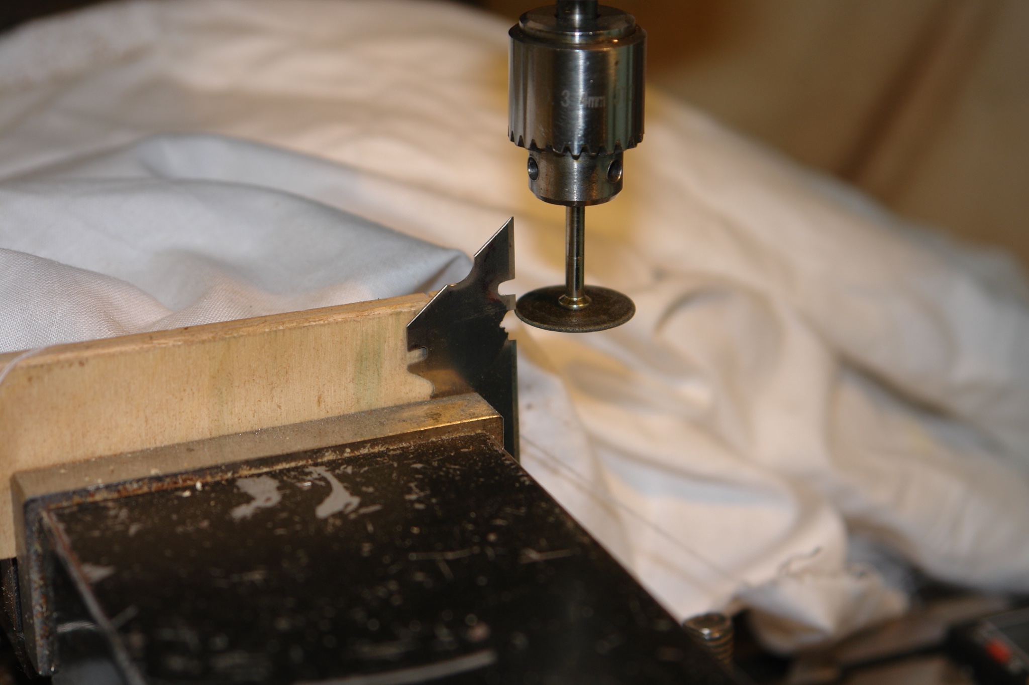
Allan - basically yes - I'm using the mill which of course has a x,y table and of course I also have z axis control on the grinding wheel. All very controllable. Eberhard - yes I believe the deckhouse is vented via the frieze and mushroom vents. My guess is that the vents are brass but the crew seem to have run out of brass polish. I will make them from polished brass.
-
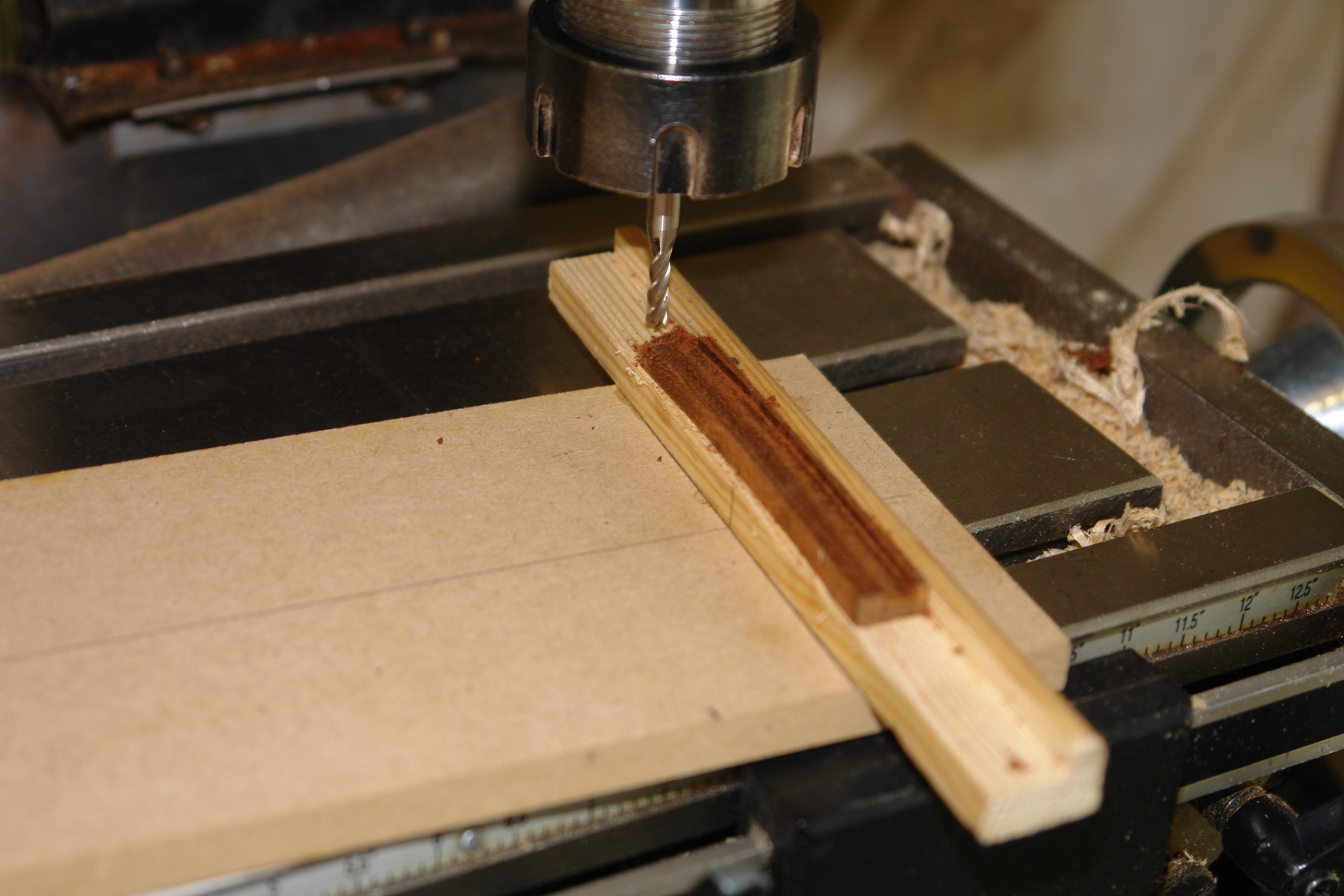
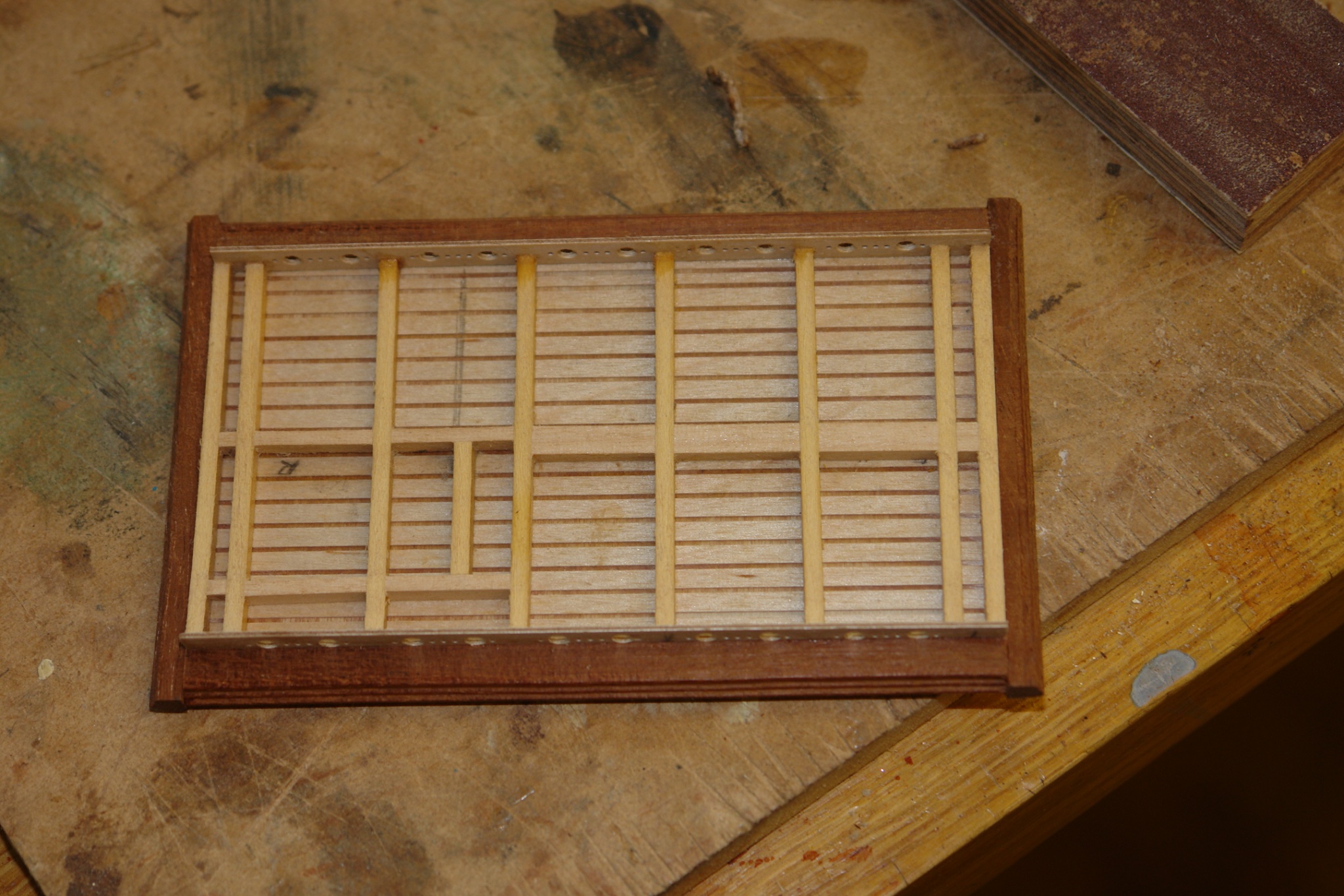
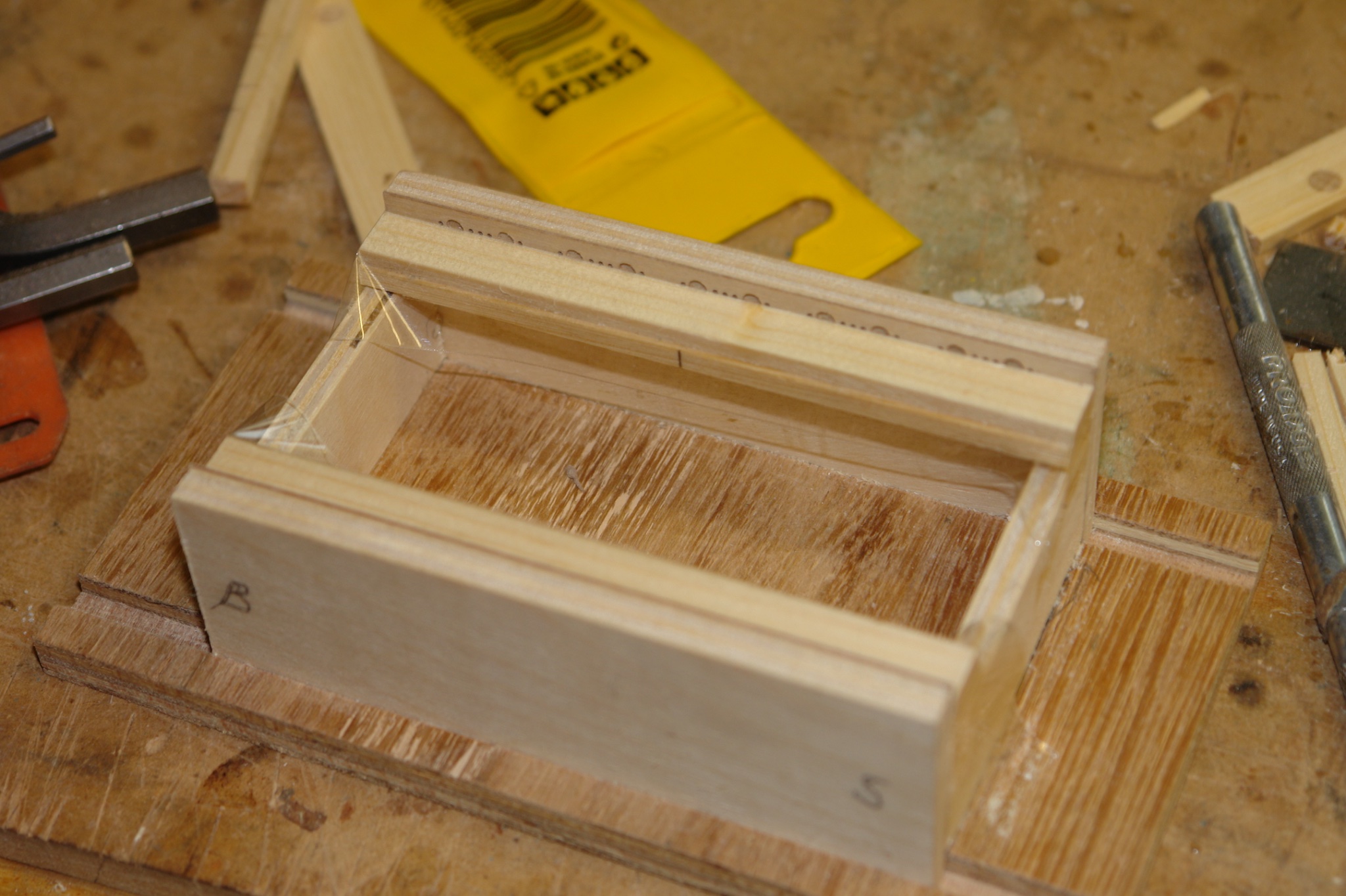
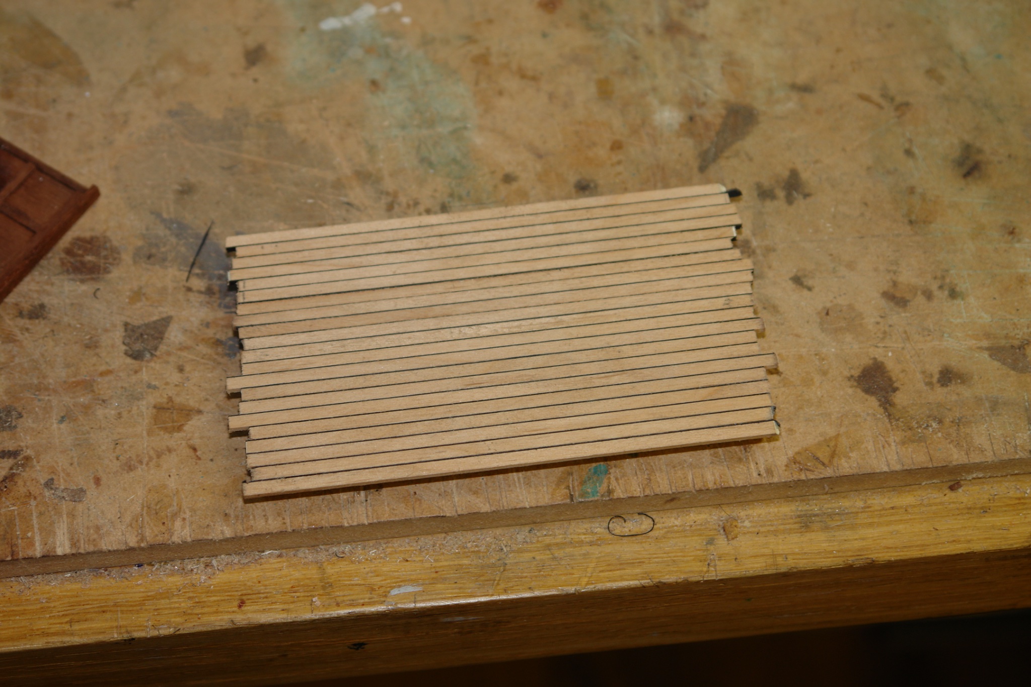
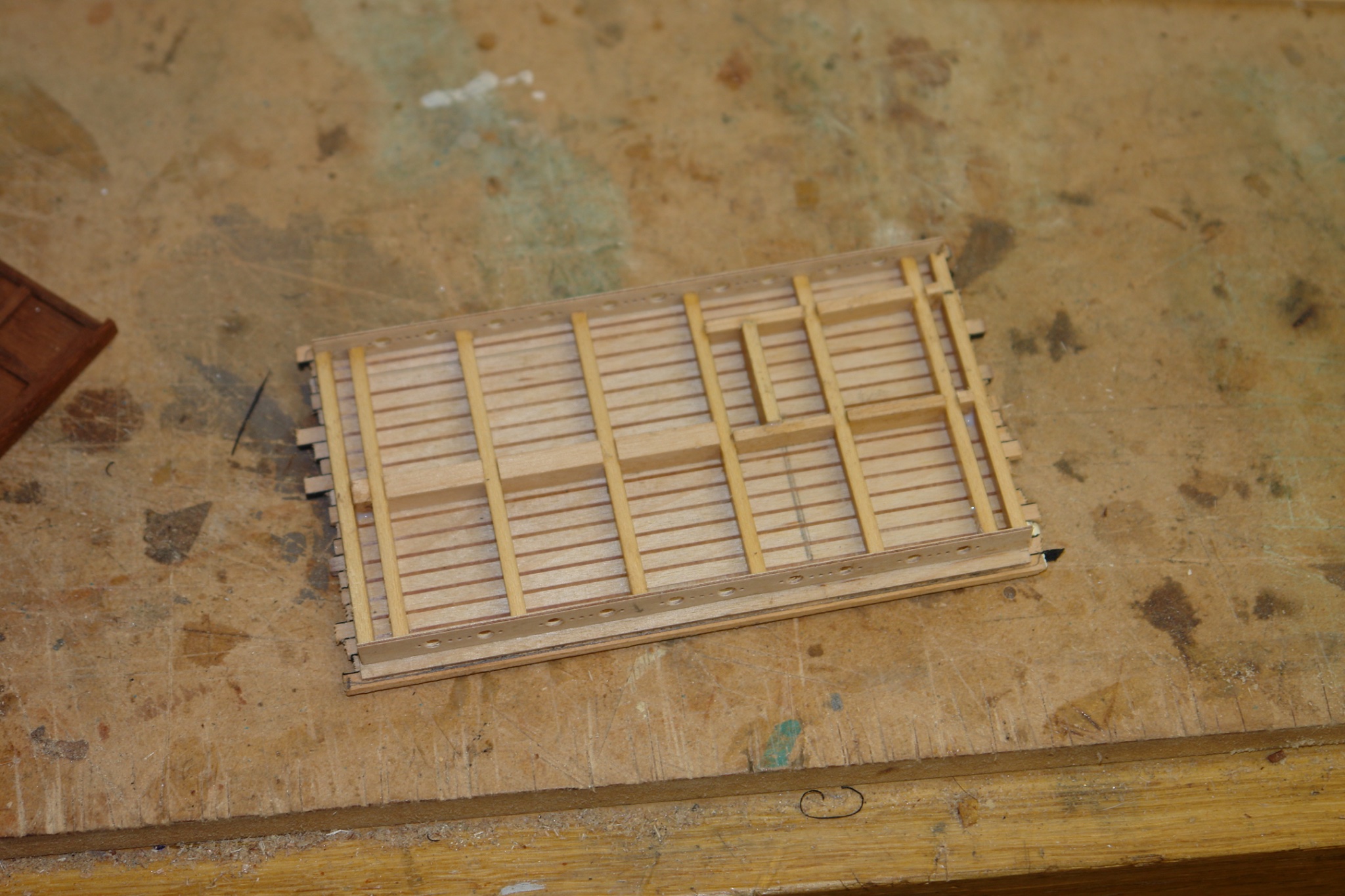
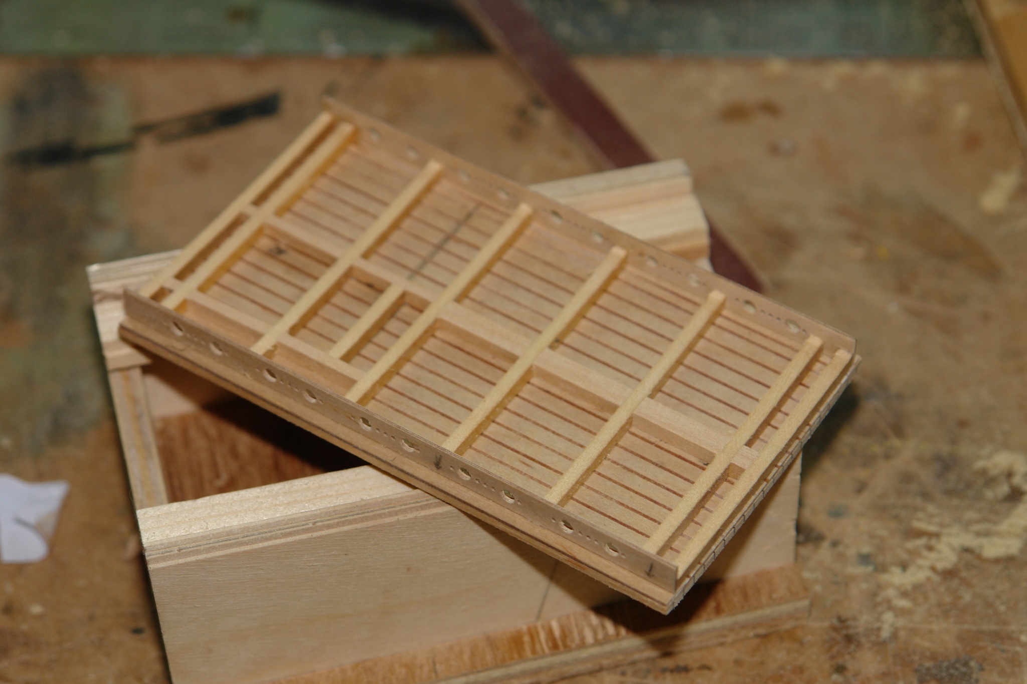
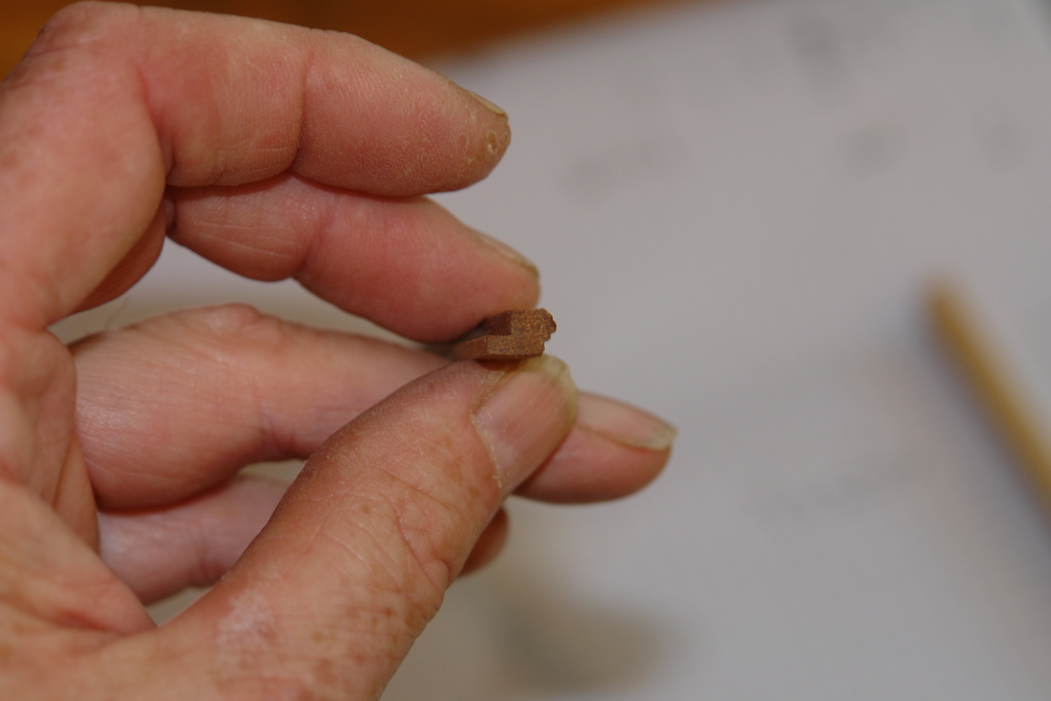
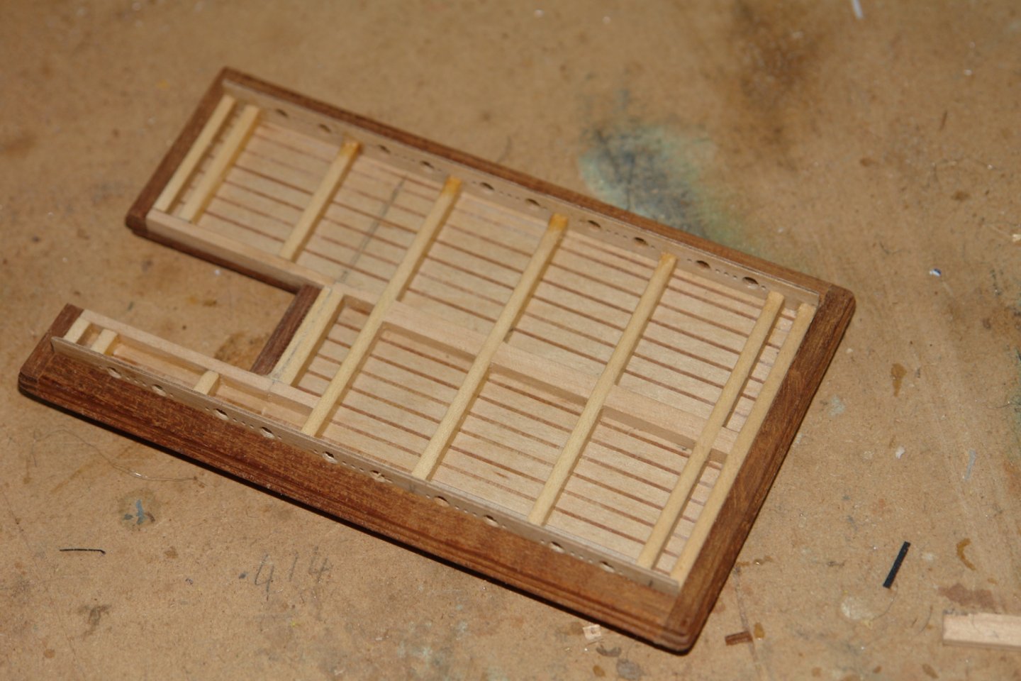
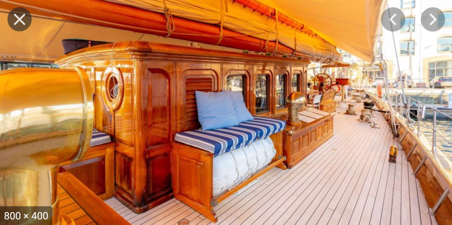
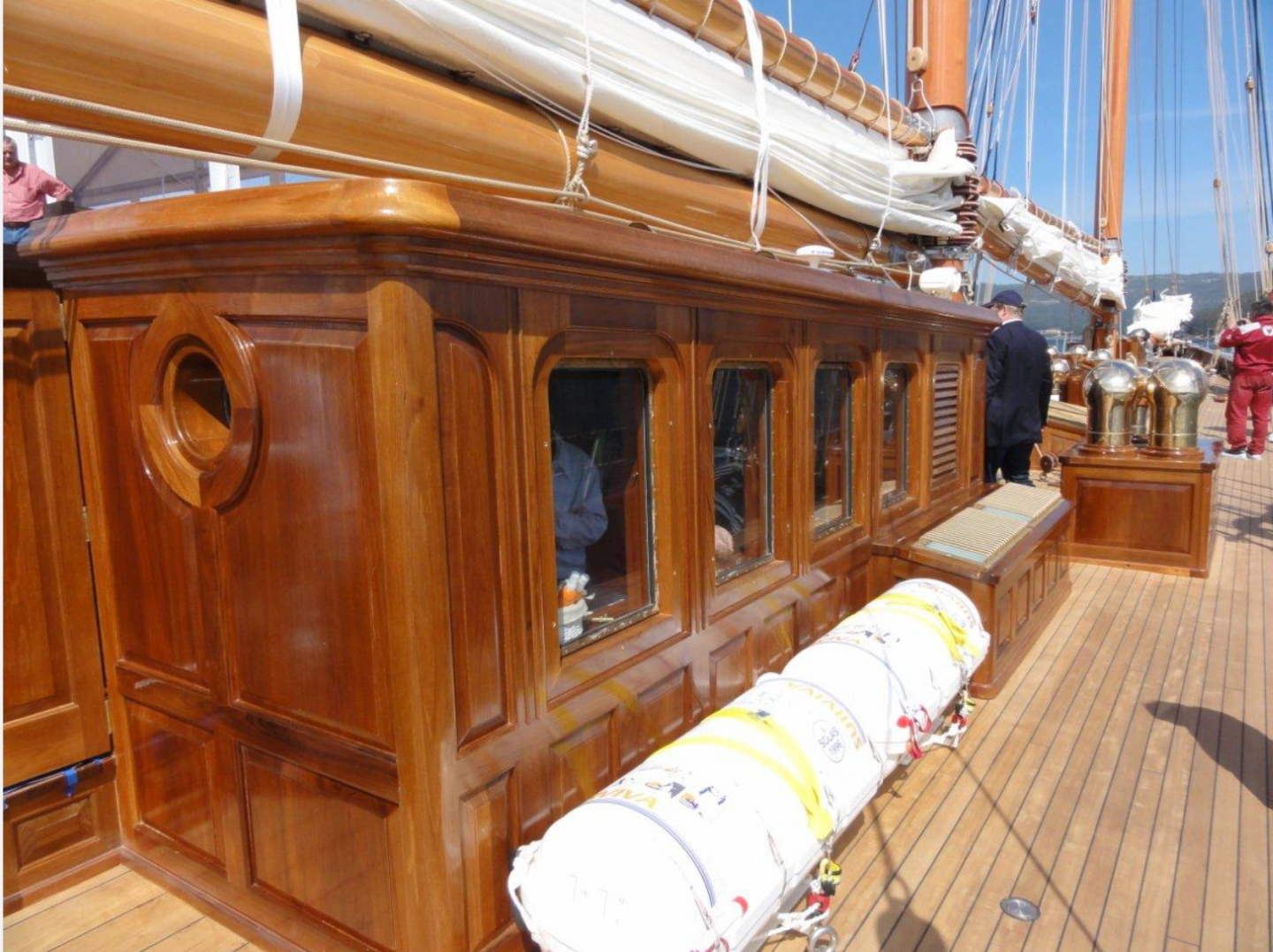
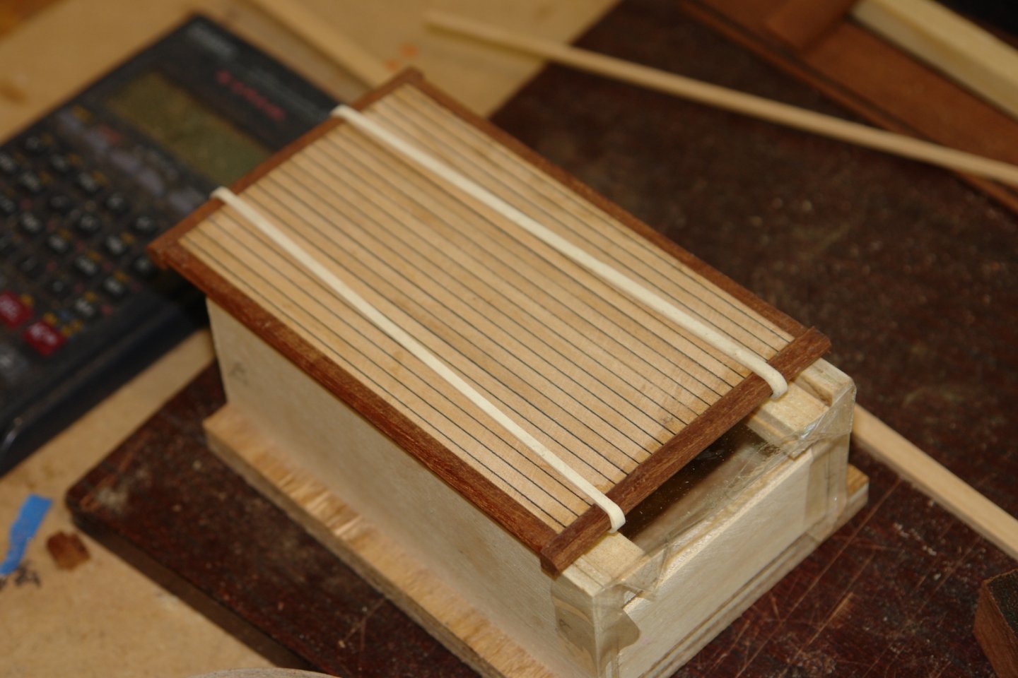
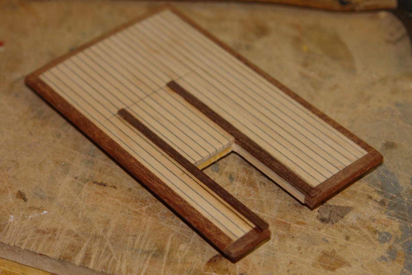
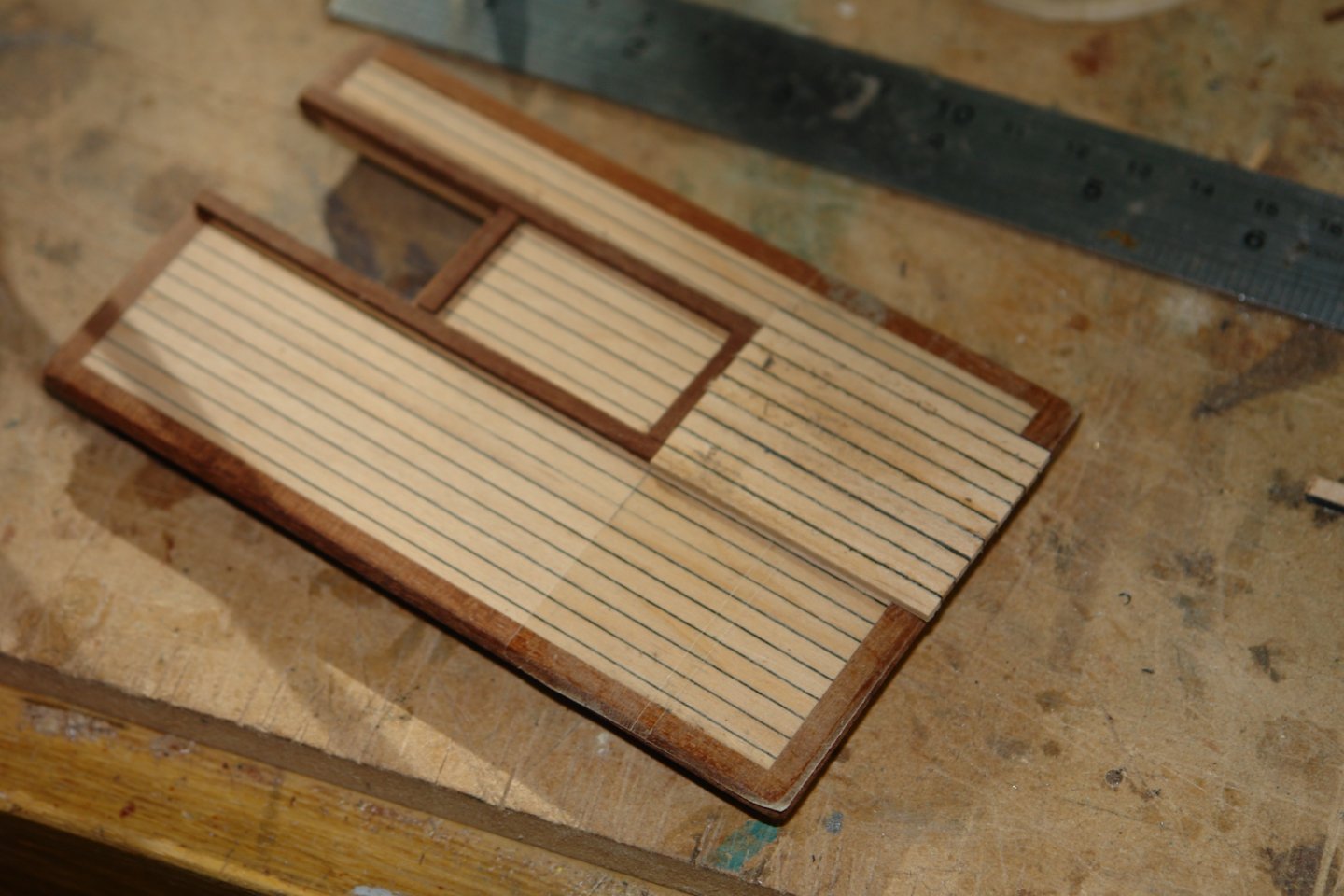
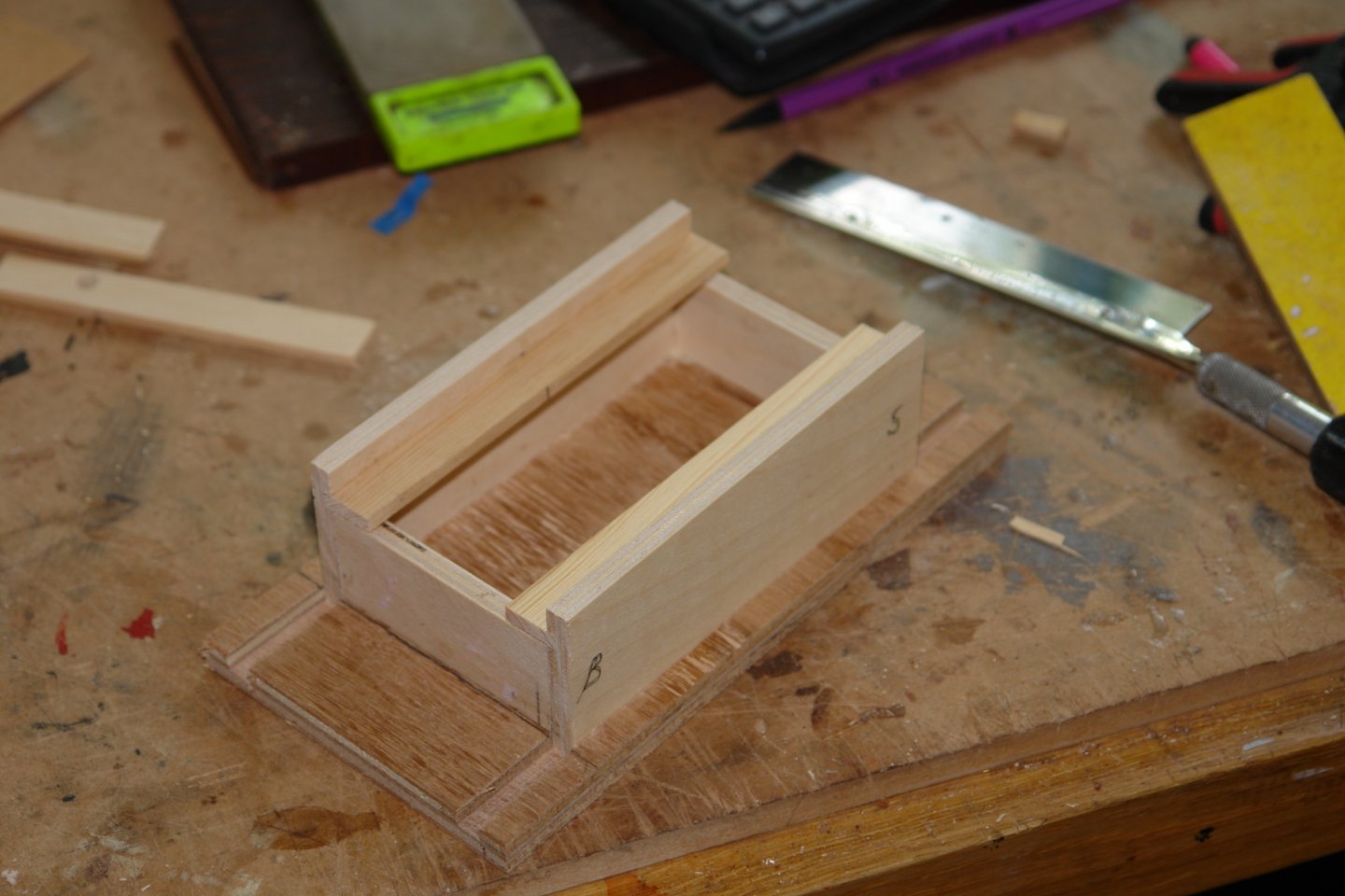
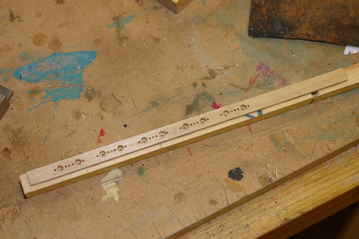
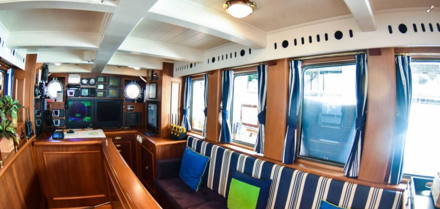
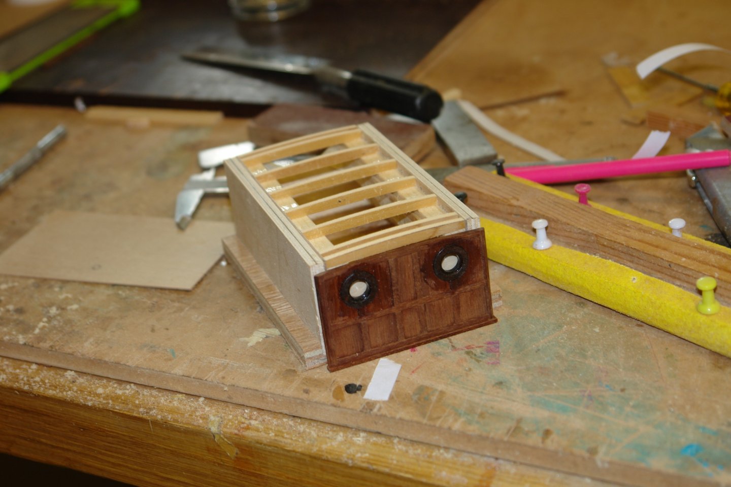
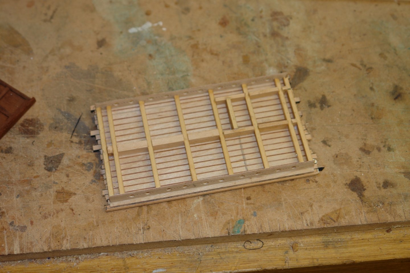
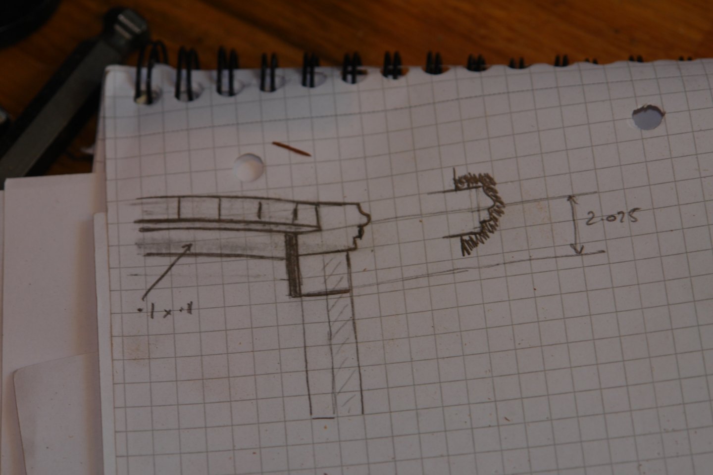
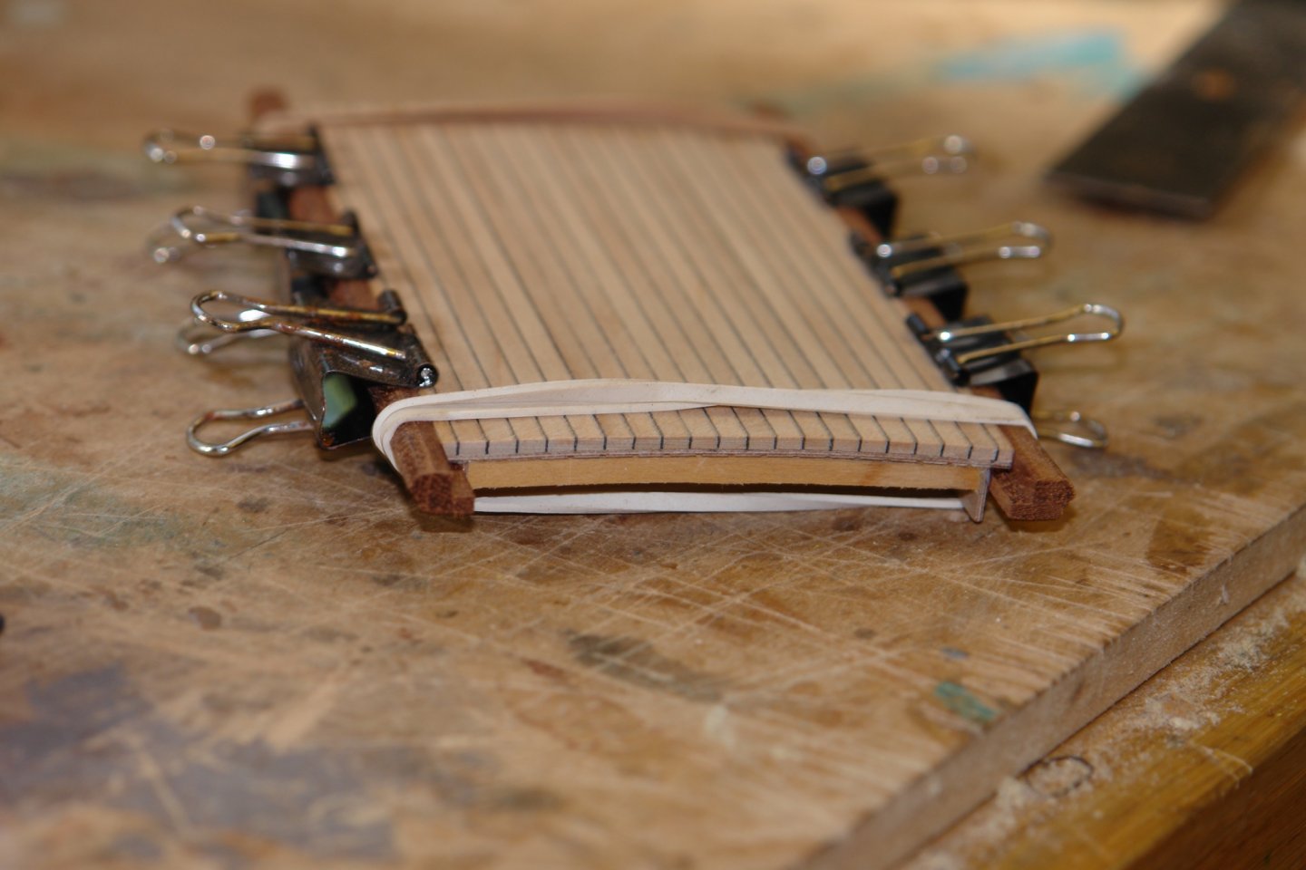
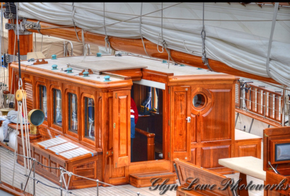
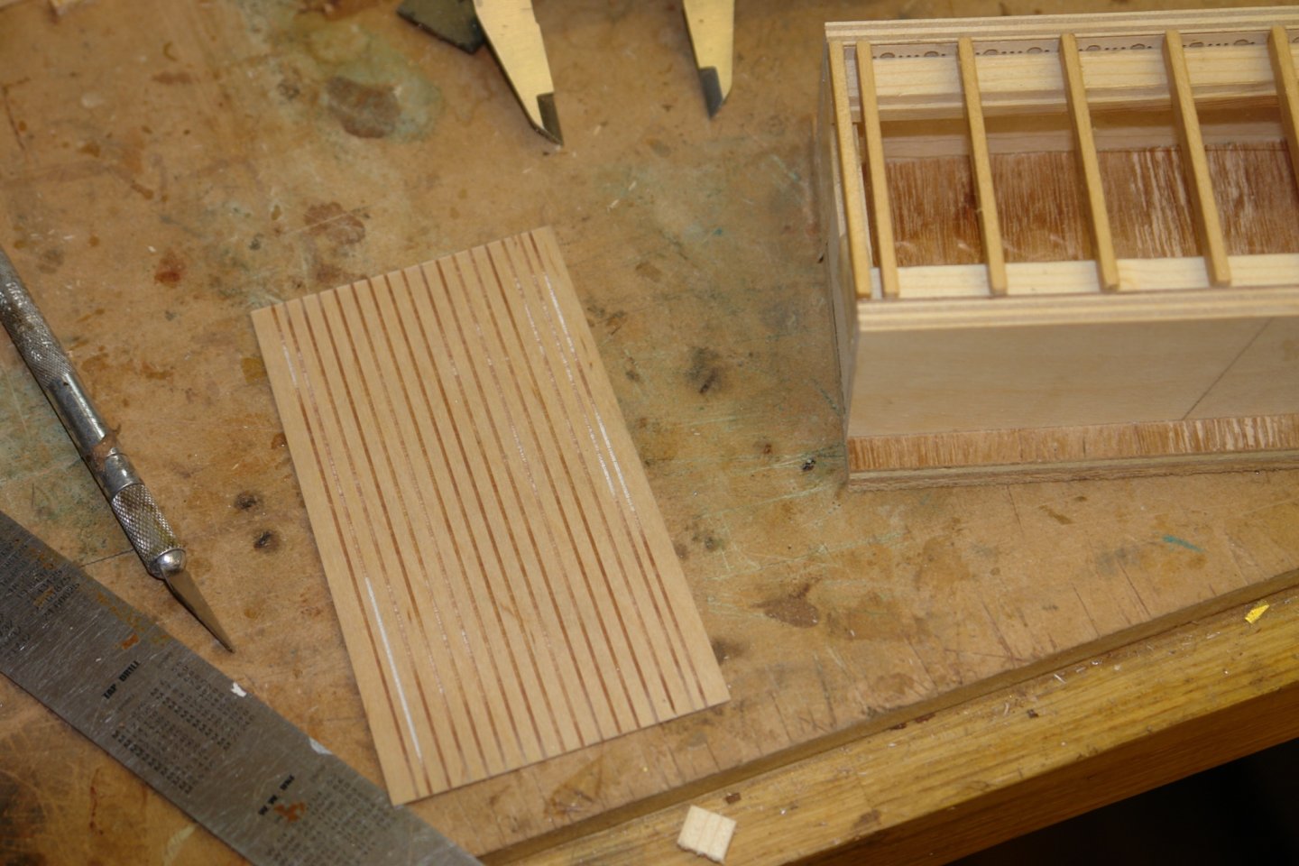
Well that's another week gone by with only modest progress. Much of the country is experiencing high Covid restrictions but our area is only on the lowest level of alert. Unfortunately the children and grandchild are still in London where more significant restrictions apply which means that we are again isolated from them. You would think this would be good for productivity but alas this is not the case. Mark, Pat, Keith, Richard and Gary, thank you for tearing yourselves away from your builds to leave supportive comments, they are much appreciated. Also thanks to everyone for all the likes and visits. The last week has been directed towards roofing, the roof of the deckhouse actually. I wanted to get the internal and external features reasonably representing the real thing. I include a couple of images as a reminder of what I am roughly aiming at. Rather than try and build onto the fragile deckhouse walls I decided to create a much more substantial building jig. I then cut the frieze planks that fit internally above the side windows. The two were cut together joined by double sided tape. There frieze planks were cut from 1/32" ply and to prevent splintering were drilled while attached to a backing plank. The friezes sits in a slot in the jig and to prevent the roof sticking to the jig it is covered where necessary with sellotape. The cross beams were then installed and glued to the frieze at each end, The top of the jig is sloped to match the deckhouse sides but the beams are mounted vertically, so lie at a small angle to the frieze. The cross beams were installed extra wide and then sanded back to match the curved profiles of the front and rear faces of the deckhouse. The ceiling of the deckhouse is painted white but has a planked appearance. This was crated by slotting a piece of 1/32" ply on the Byrnes saw using a .020" width slitting saw. On the reverse side of the ply the roof was planked in the same manner as the deck. This was then glued to the roof frame on the jig. Once dry the roof was removed from the jig and additional beam detail was added. The edges were then trimmed. Before the roof was placed back on the jig and sanded to a smooth curved finish. The roof edge is made from a substantial piece of profiled mahogany and I wanted the profile to be reasonably representative. The sketch shows the profile which is 0.2" high. To create the profile I made myself a scraper from an old boxcutter blade. Making the long edge planks was then a fairly straightforward scraping job. Once made these were glued to the roof. I now have to make the equivalent pieces for the front and rear of the roof but these will be curved and will therefore be a bit trickier.


-
Kurt Yes that's the way I do it. I burn off the plastic coating before threading the wire through the crimping tube as it allows the tube to be much smaller and more to scale.
-
More than I would have guessed Eberhard. She is a fascinating little vessel. Logically she would have been very vulnerable to fire from smaller quick firing guns. I guess her rate of fire was quite low and presume her accuracy was somewhat problematic. The crew must have been quite nervous between shots.
-
Nicely done with the shells Eberhard. Do you know how many shells the magazine held? With such a large gun mounted on a small hull I am assuming that the magazine capacity was very limited.
-
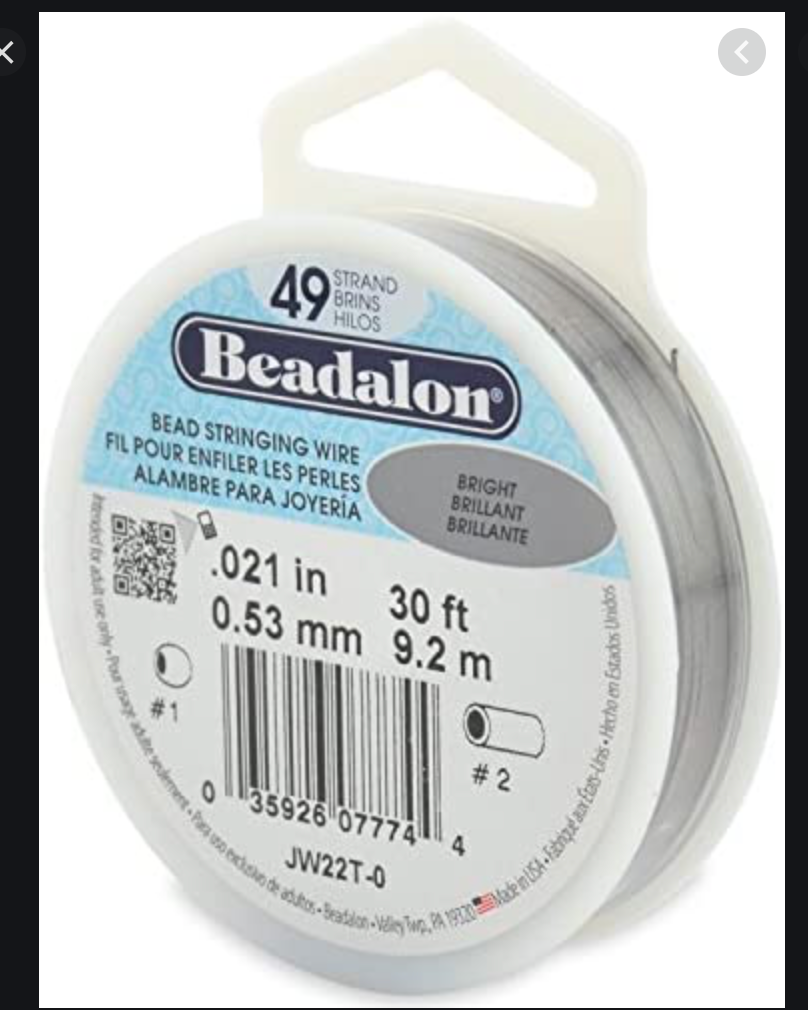
Allan I use beading wire, as do a number of fellow MWS members. You can get it in various diameters. Its quite flexible and does not kink easily. It is plastic coated but if you use the clear plastic cover its virtually invisible.
-
Allan, I did wonder whether it was to facilitate wheelchair access - very commendable. My sailing days are behind me but I do know that the tack that the boat is on is fairy important when choosing the head to occupy (port or starboard). Presumably the crew won't mind changing tacks to assist sailors with limited mobility.