KeithAug
-
Posts
3,986 -
Joined
-
Last visited
Content Type
Profiles
Forums
Gallery
Events
Everything posted by KeithAug
-
 Brian, remarkably they do. I think the brownish red looks great and agree that a bright red wouldn't have worked nearly so well. I look forward to the next instalment.
 -
Very nice work on framing out the clinker shell. I look forward to seeing more. My workshop started out at 7 degrees today and by mid afternoon had reached 12. I recall thinking it was getting a bit too warm.
-
I have every sympathy Keith. I have spent loads of time staring at out of focus images of Germania most of which lead me to different conclusions about the same part. At lest you have the advantage that a better photo is unlikely to turn up. Nice detail on the rudder chains.
-
Andrea, Very creative recycling. Your English is fine.
- 9 replies
-
- 1
-

-
- Schooner
- training vessel
- (and 1 more)
-
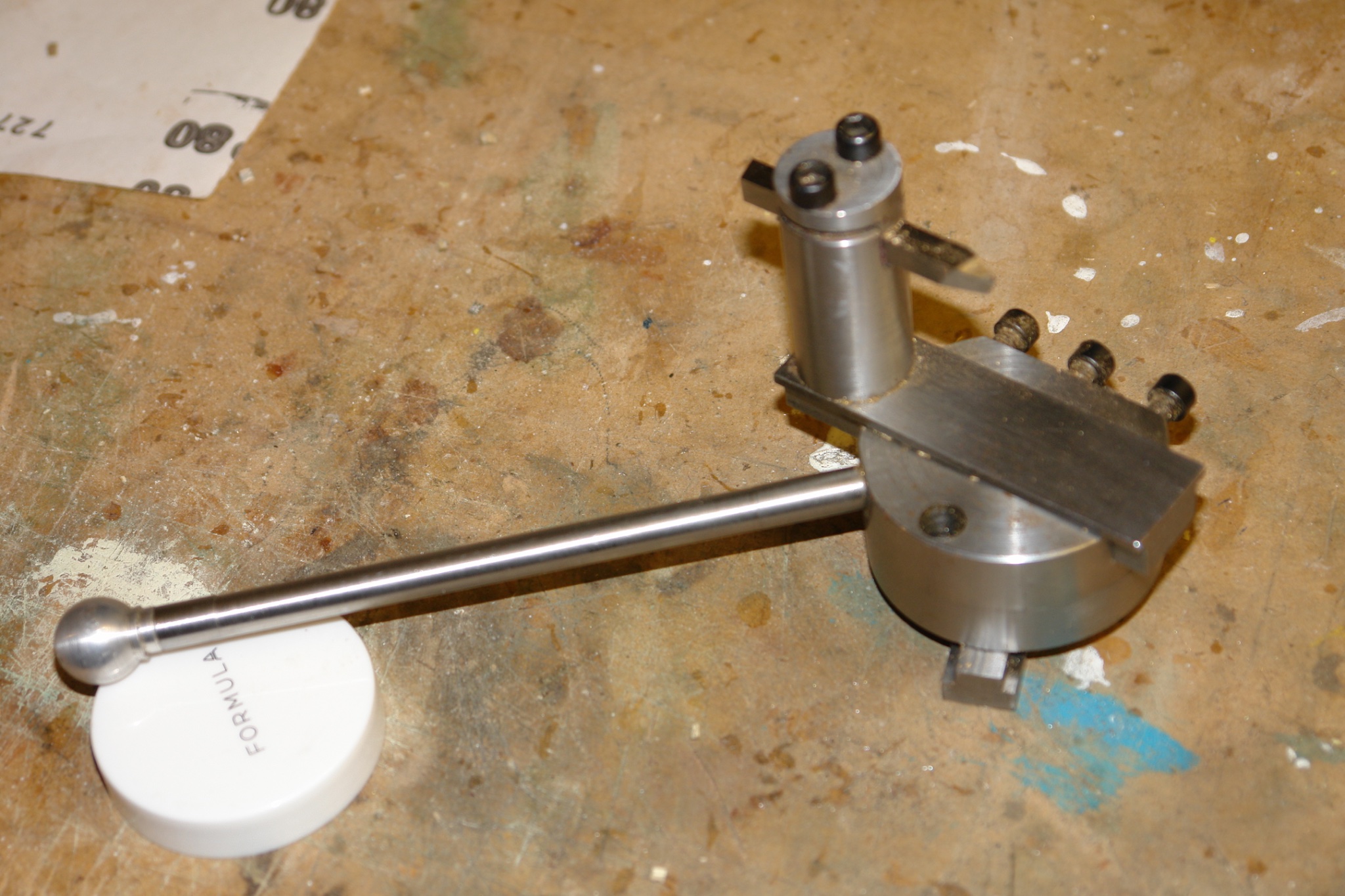
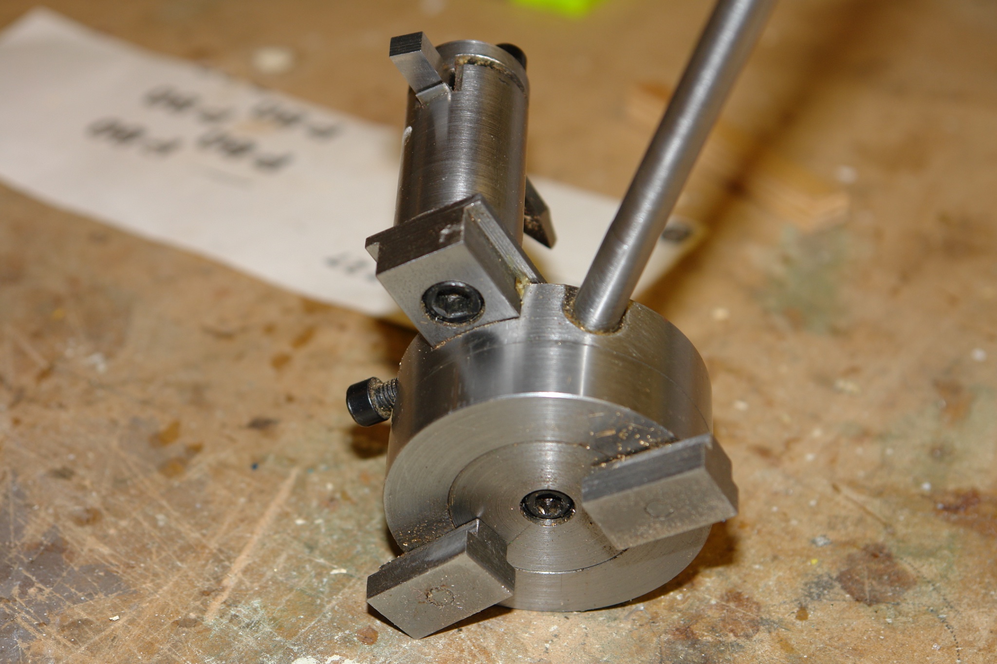
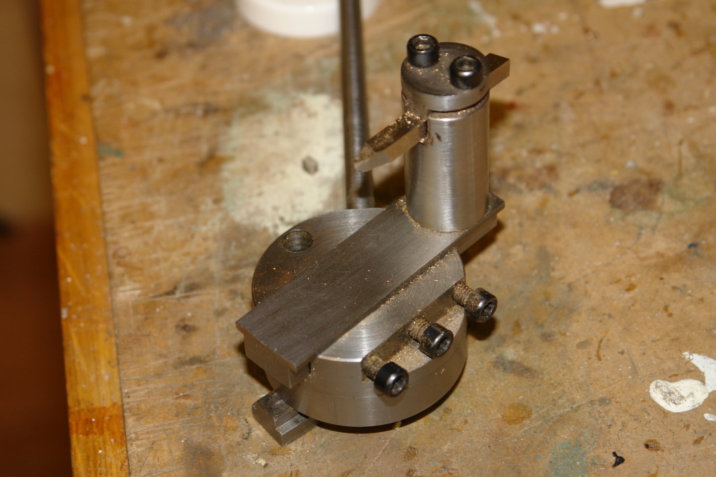
Eberhard / Druxey, I was limited by the size of the bar I had for the base. If you look at the top view you will see a hole near the handle. The cap head bolts which hold the "T" nuts are recessed into the fixed base and are accessed by this hole. The top is turned through 180 deg to access the second cap bolt. Thank you for your kind remarks Druxey.
-
Eberhard - nothing special, home made. I made it so that it will cut balls as well as concave surfaces. Eberhard, Undecided - I'm tempted to leave them but think they will look better in black.


-
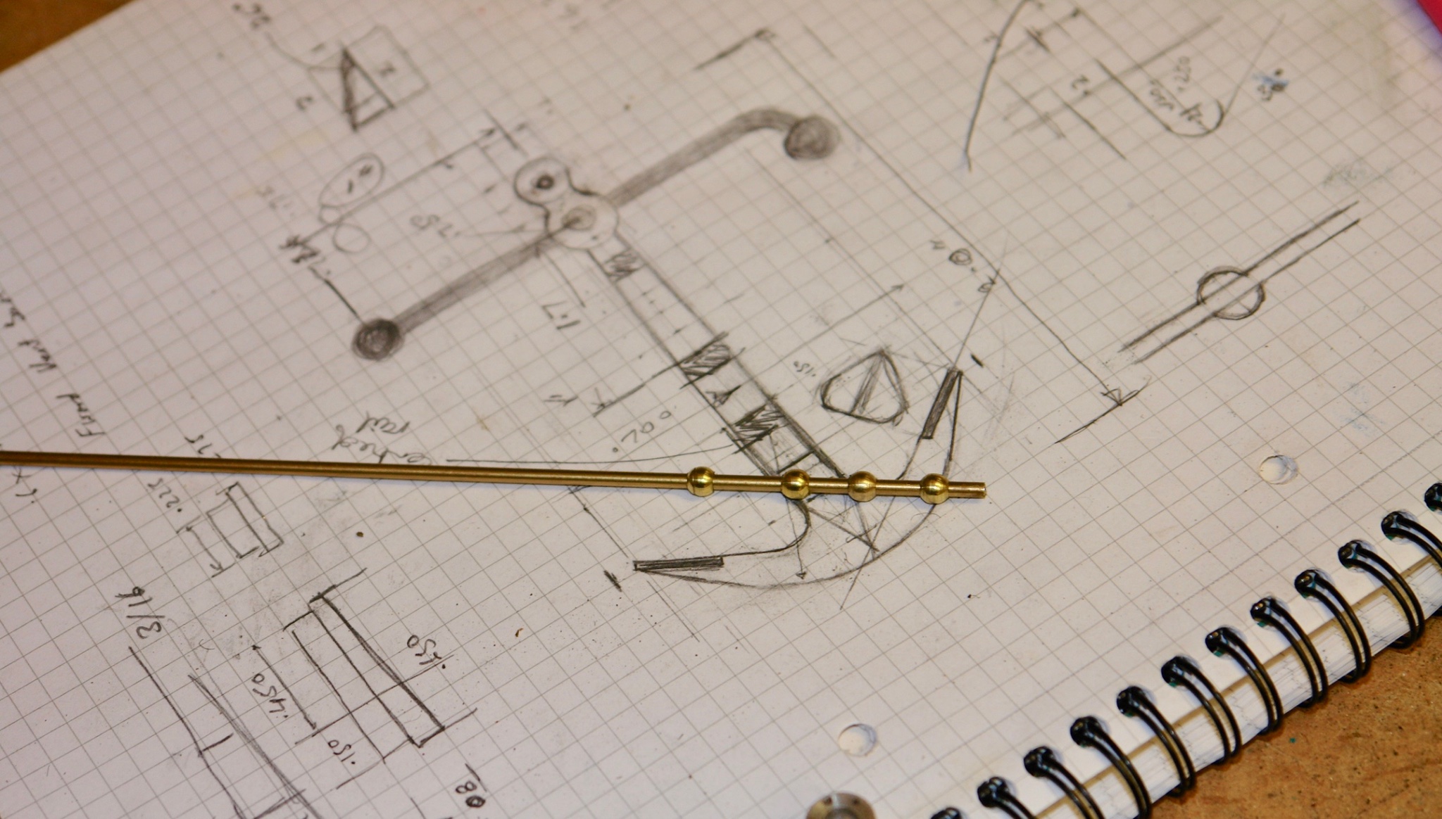
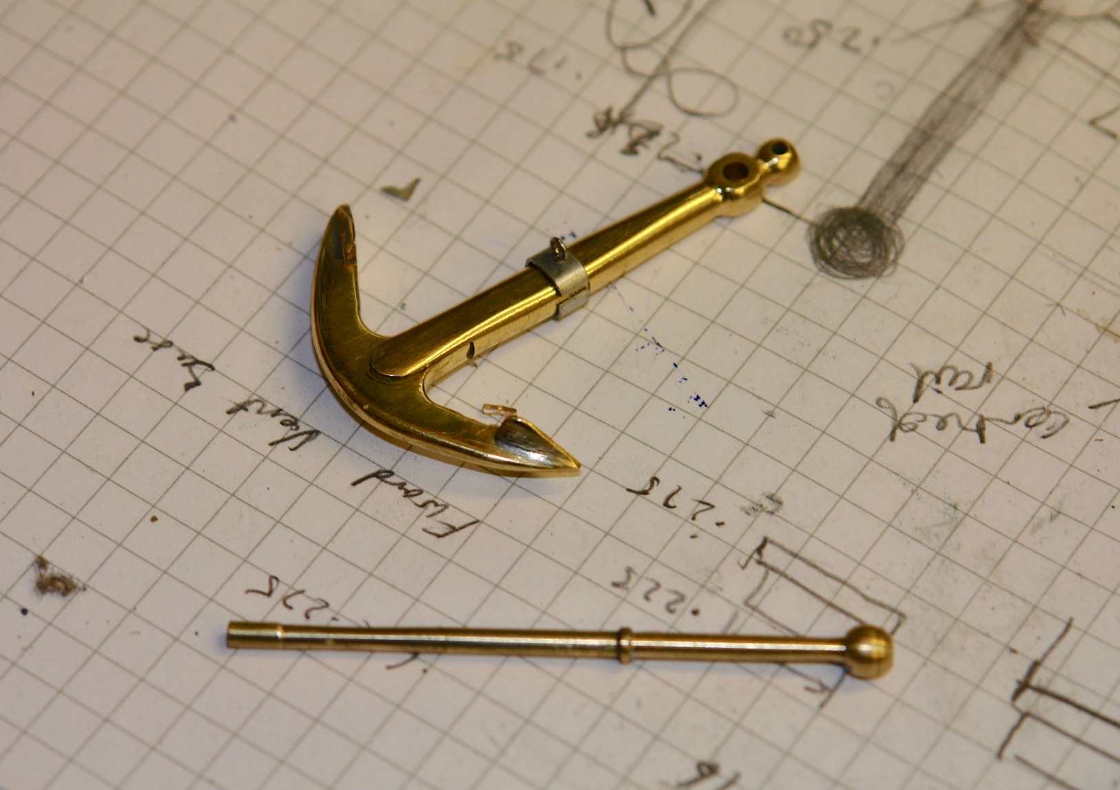
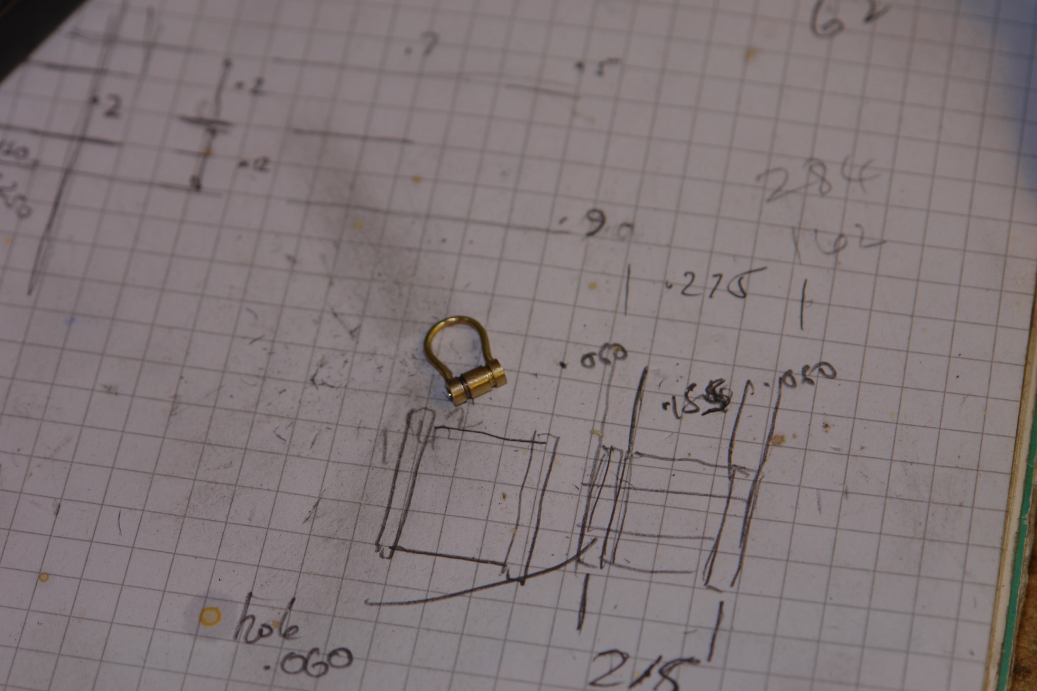
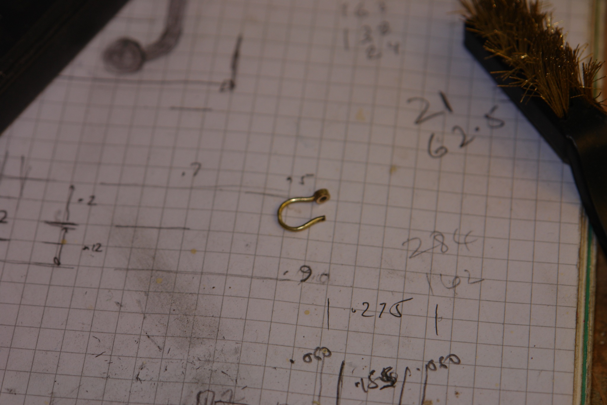
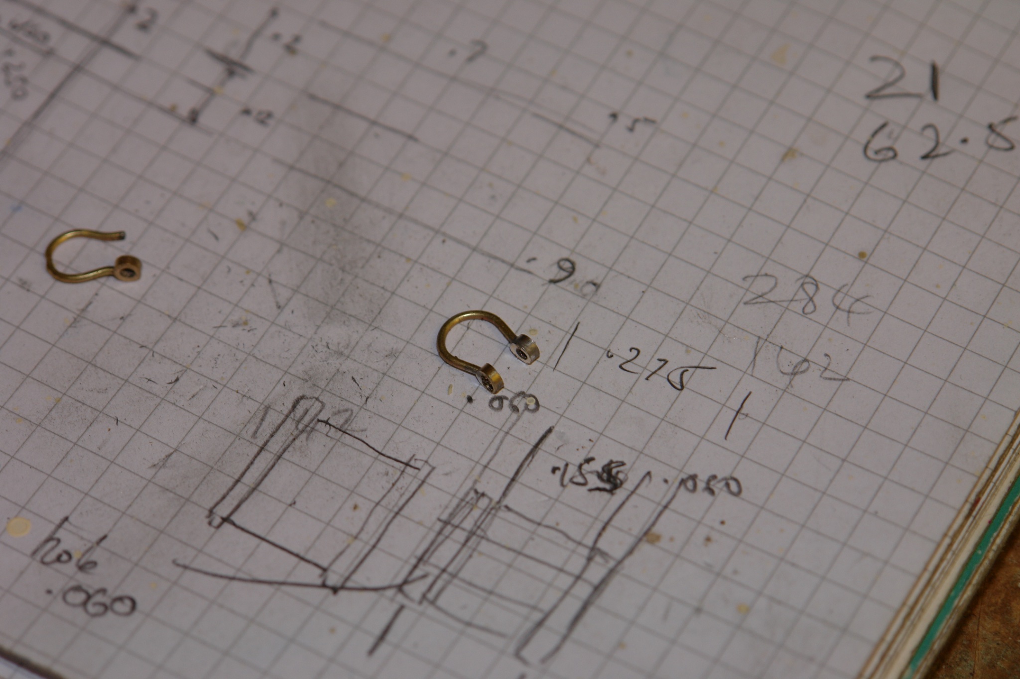
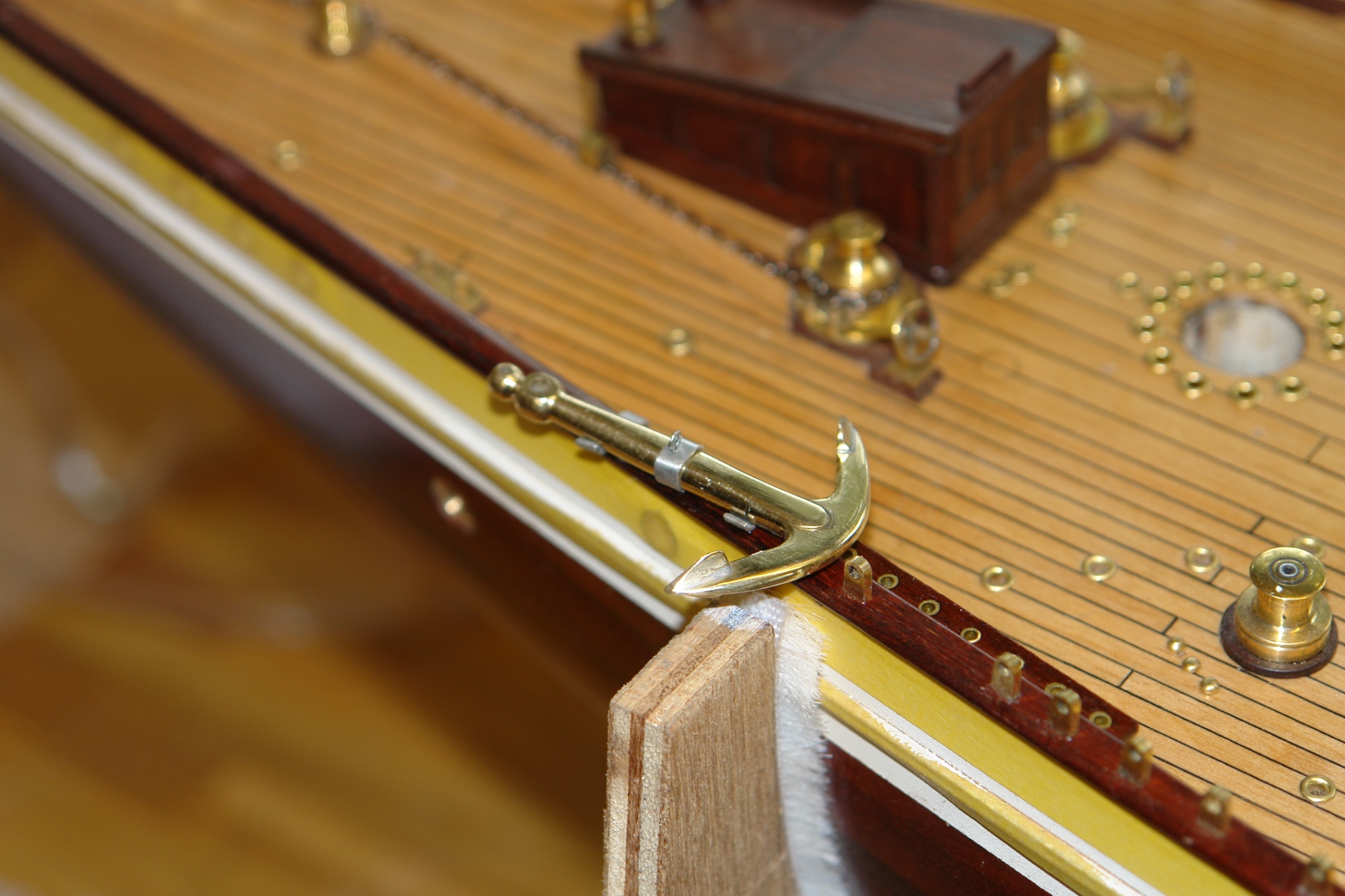
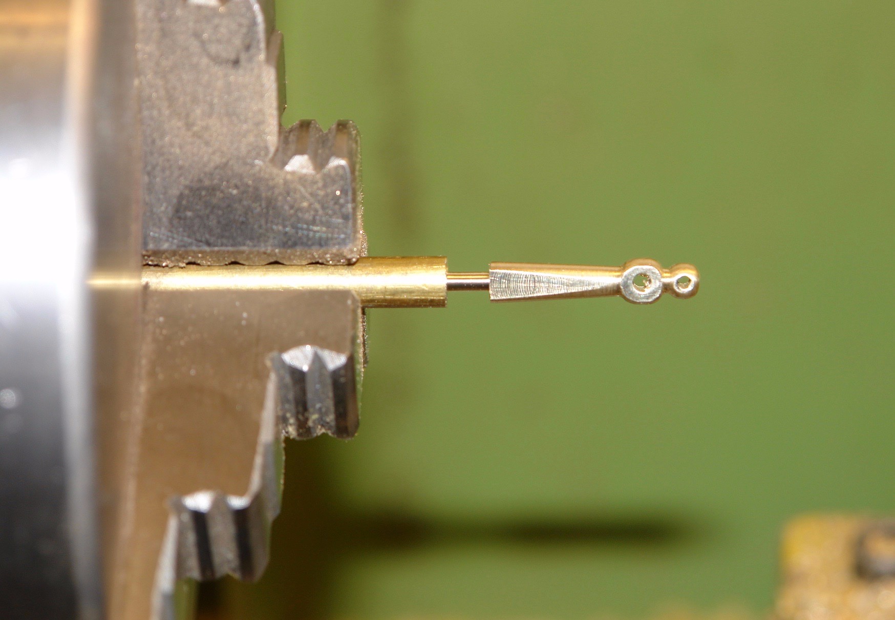
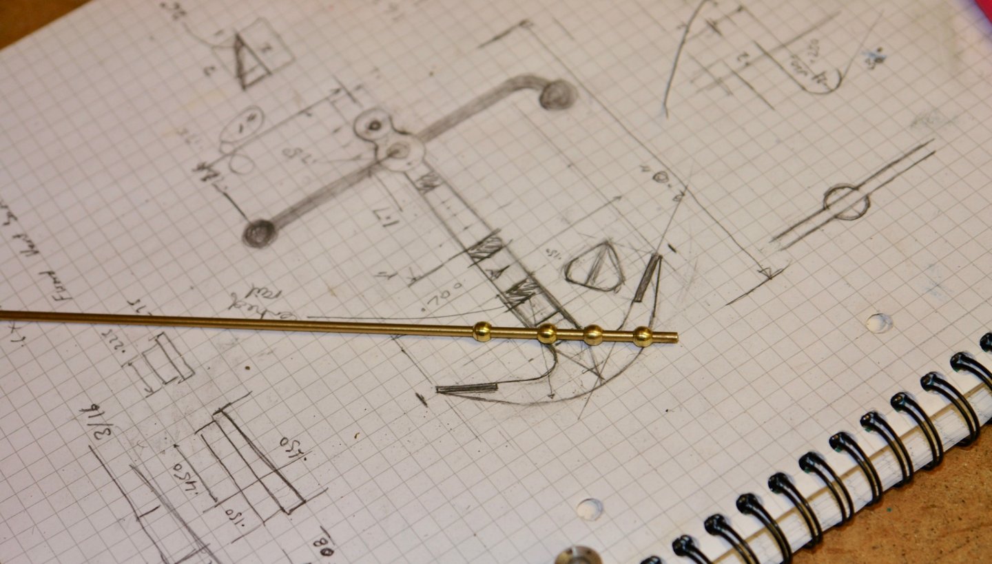
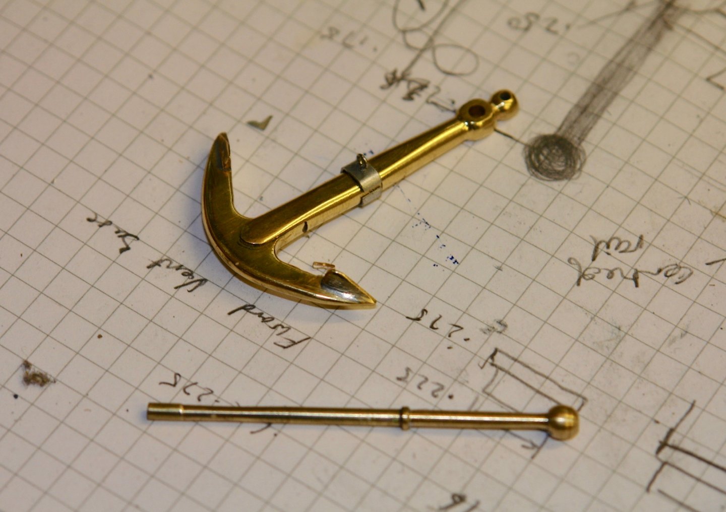
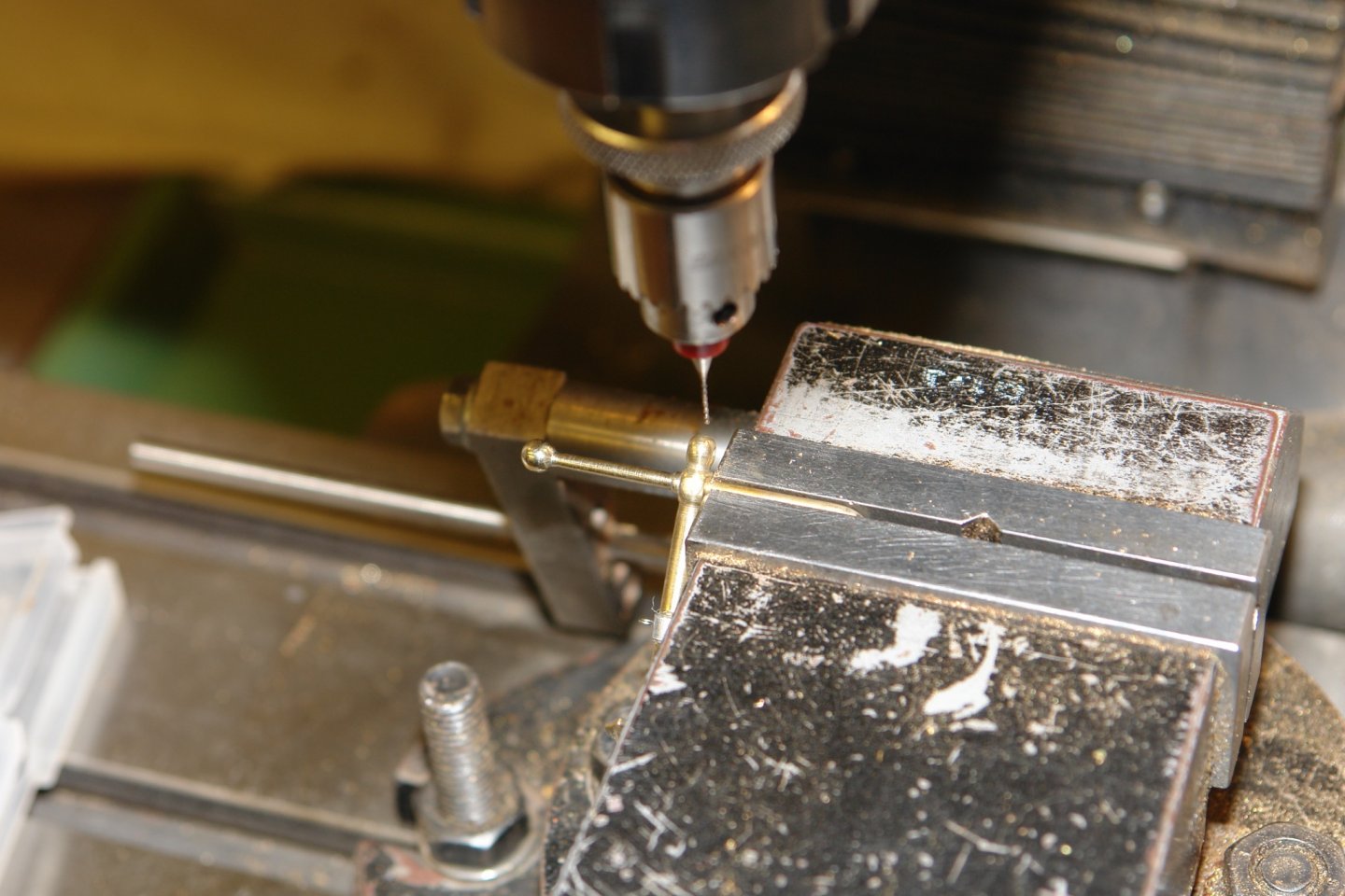
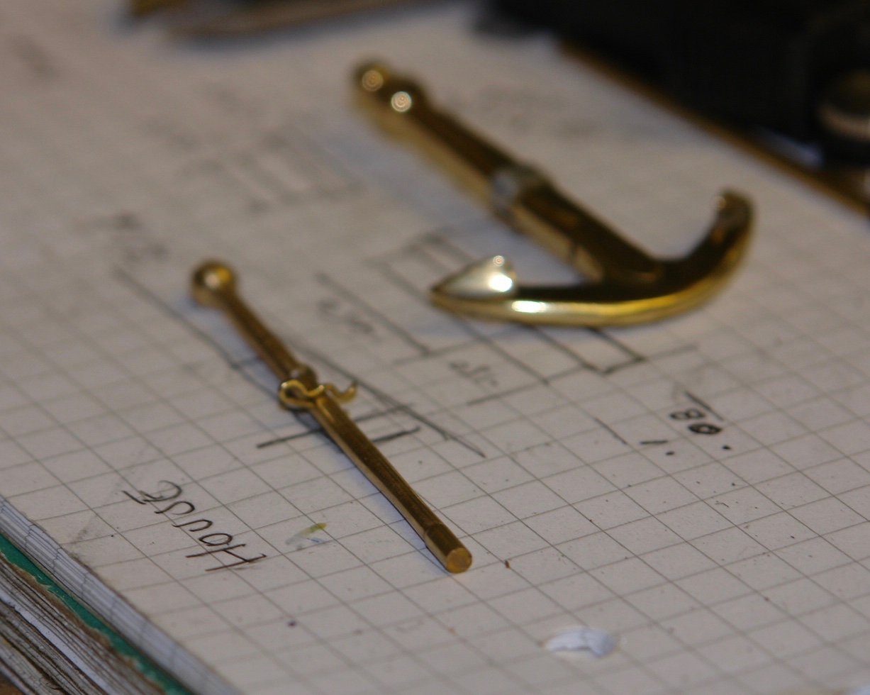
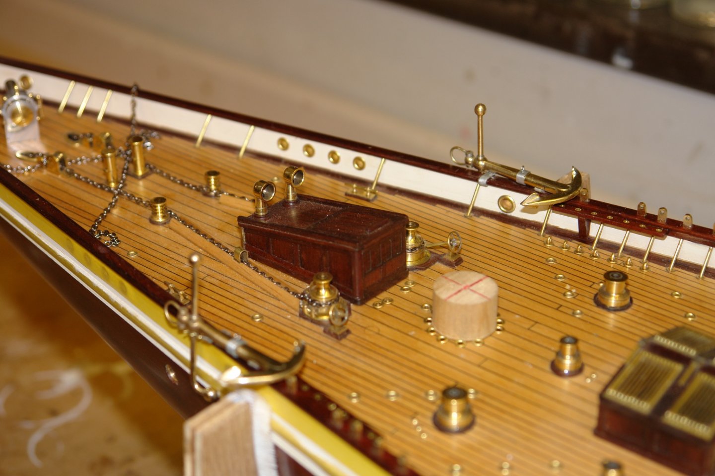
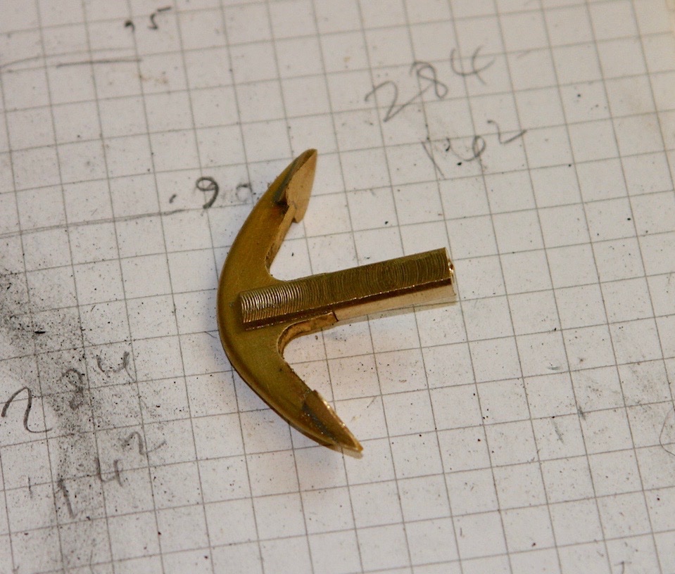
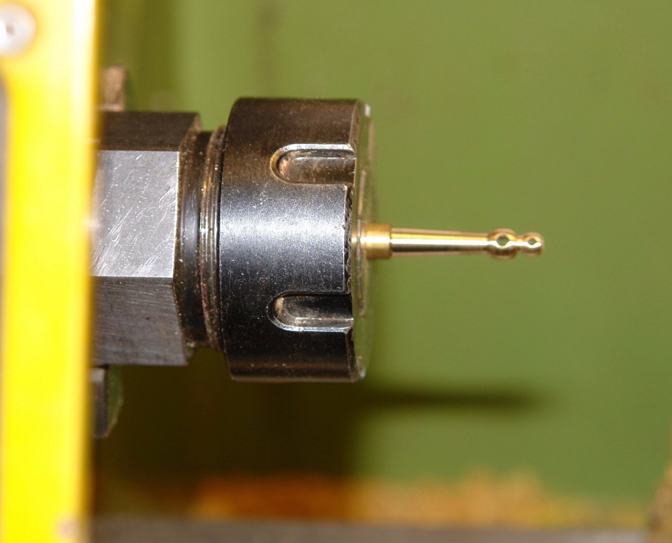
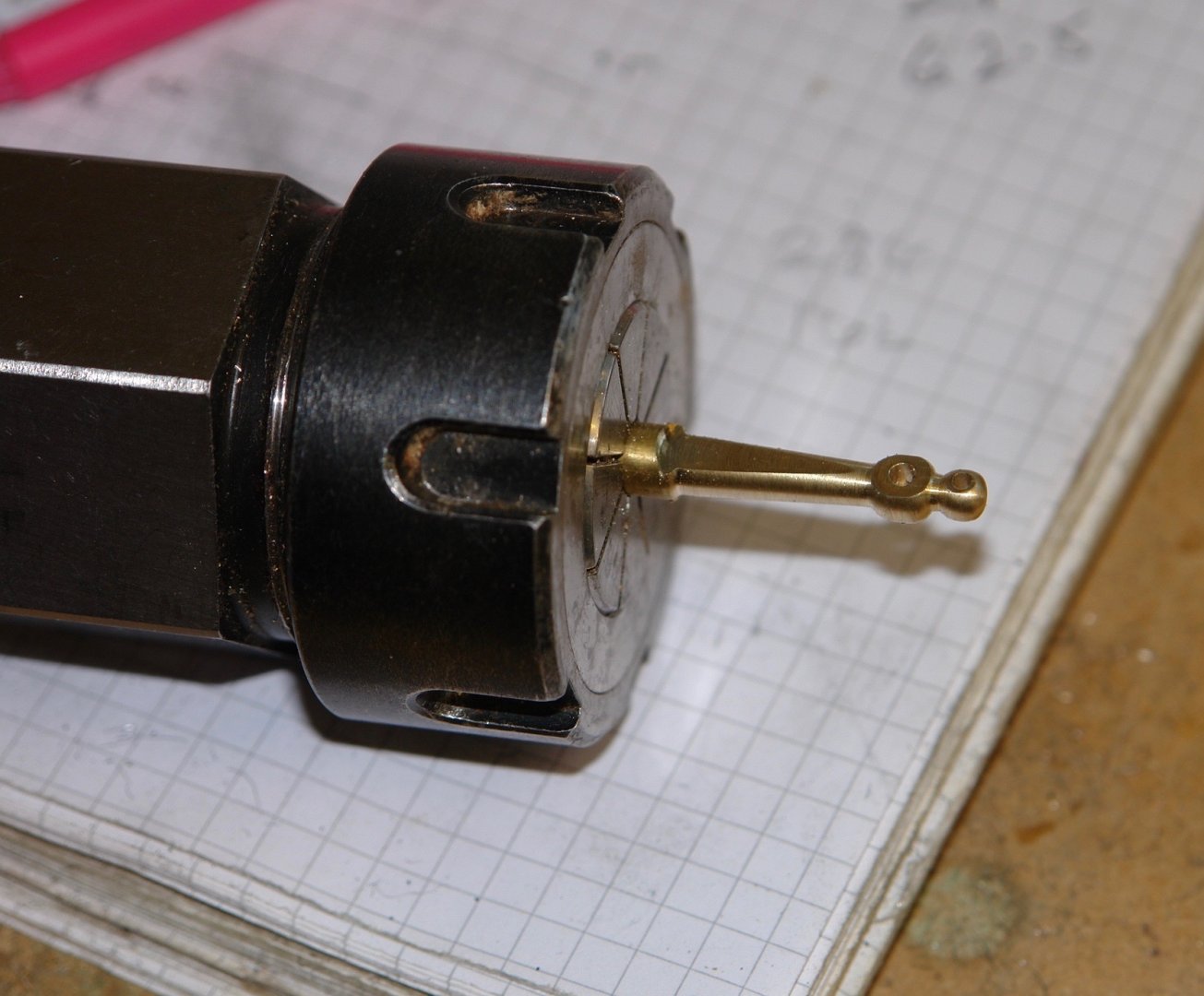
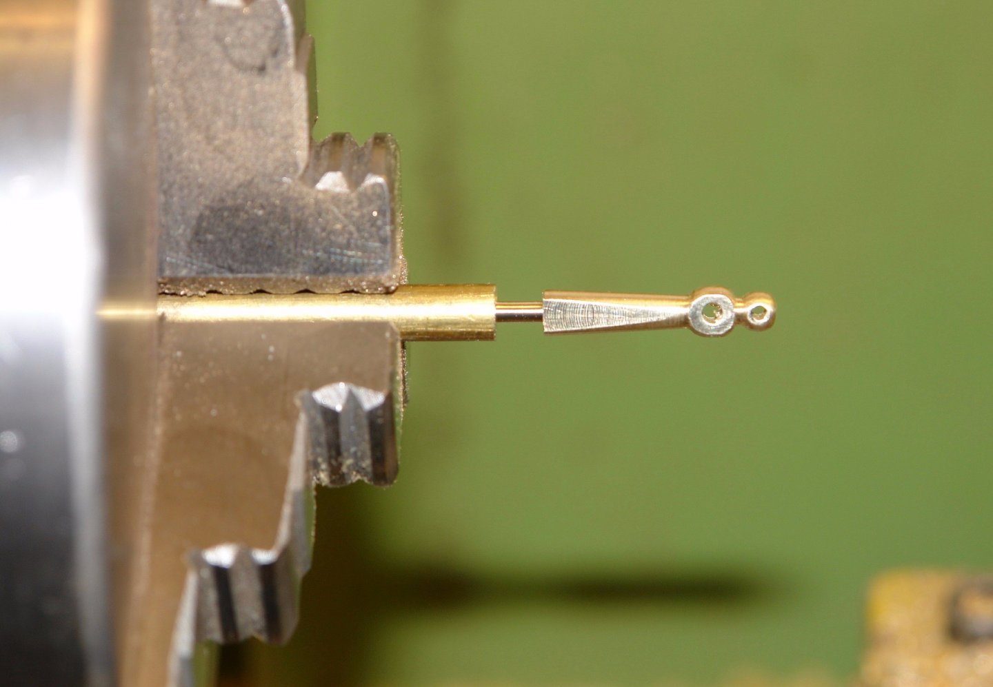
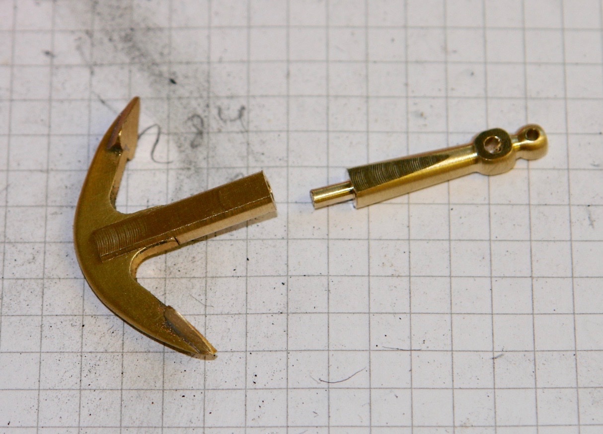
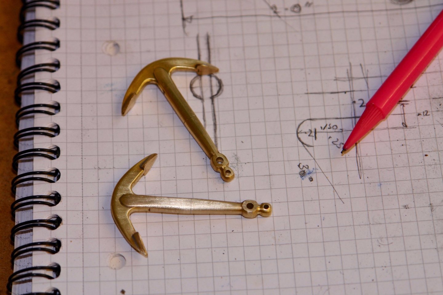
I continued working on the anchors. I dug out the lathe ball turning attachment to make the 4 small balls that sit on the ends of the 2 stocks. They were temporarily parked on a 3/32" rod awaiting use. They are .150" diameter. The stock was turned from 3/32" rod - taper turned to slim down towards both ends. The stock was heated to soften the brass for later bending. A ball was soldered on one end and a ring added to butt up against the shank. The stock was then inserted into the shank and a .025" hole was cross drilled to take the keep pin. The keep pin was made from wire. The stock was inserted in the shank and the end was bent through 90 degrees. The ball was then soldered on the other end (the metal clip is preventing the ball moving during soldering). A bit of polishing followed. Next the 2 shackles were made. I cut a piece of small bore tube on the lathe ( the grooves are to guide later cutting). The tubes were drilled with 2 transverse holes and a length of .025"m wire and soldered it in place. The central piece of tube was then cut away to reveal my useless soldering. The next one went better. A shackle retaining pin was then made and the anchors were complete. Then temporarily position to see how they looked.

-
Eberhard I tend to agree, particularly where more than a couple of identical items are being made. The case is a bit more marginal when only a couple of items are required where the preparation time can be as long as the fabrication alternative. Keith - I will add it to the plan although I might wait for an outdoors photo opportunity. The weather here isn't very conducive to outdoor photo sessions at the moment. Thank you Gary and Pat and to everyone else who has visited.
-
I do like unusual ships and once again your description is both detailed and informative. A fine model even down to the detail of the flag. I don’t know how you can part with your creations when finished. I would be interested to know the purpose of the forward deck house? sorry to hear that you suffered from COVID by pleased you made a good recovery, Keep safe.
- 33 replies
-
- 4
-
-
- James B Colgate
- whaleback
- (and 2 more)
-
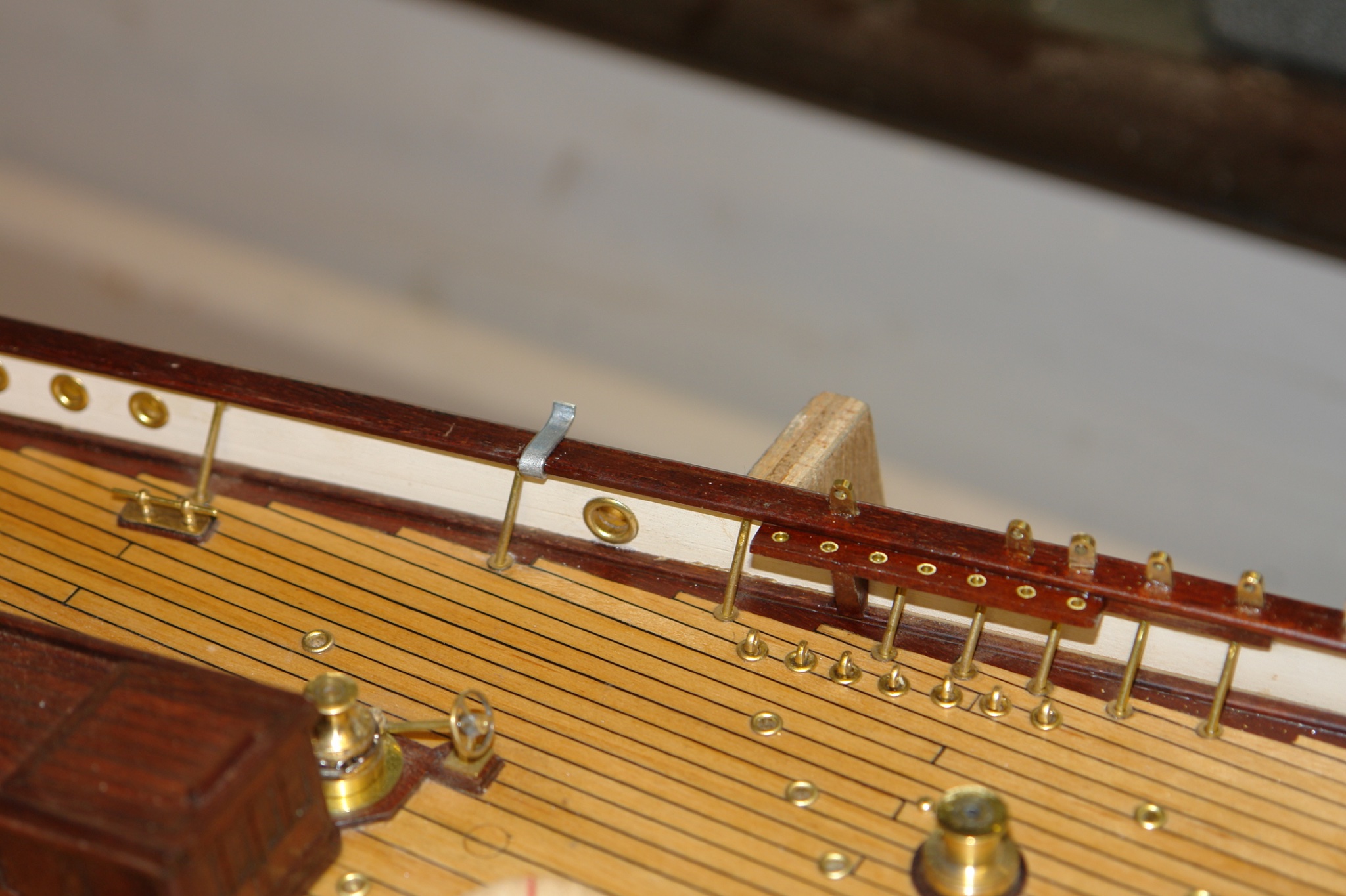
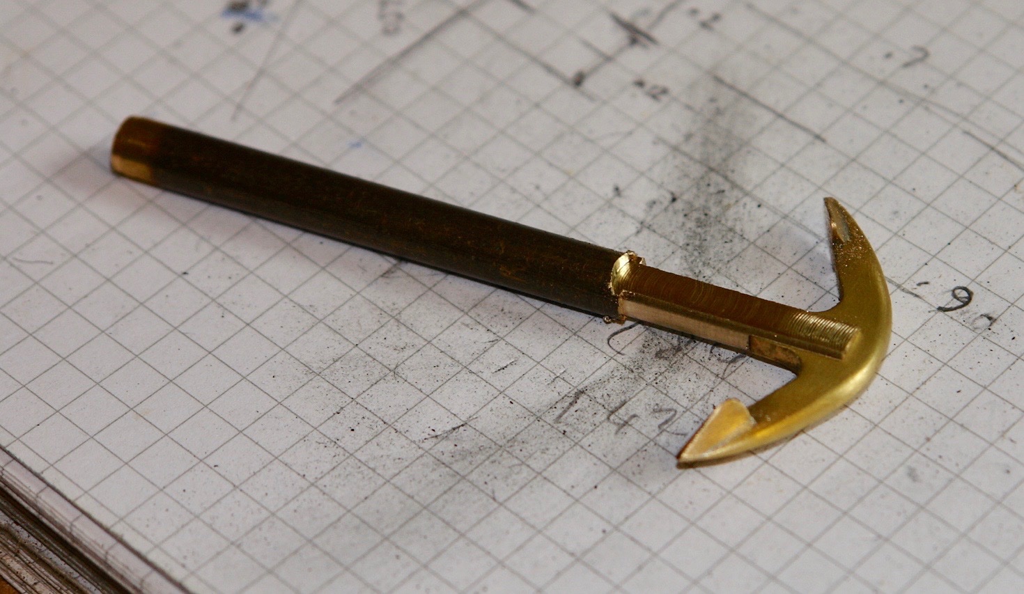
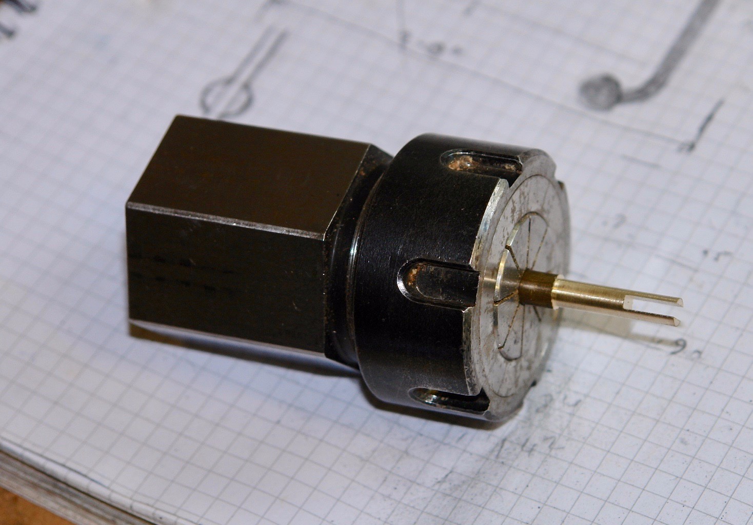
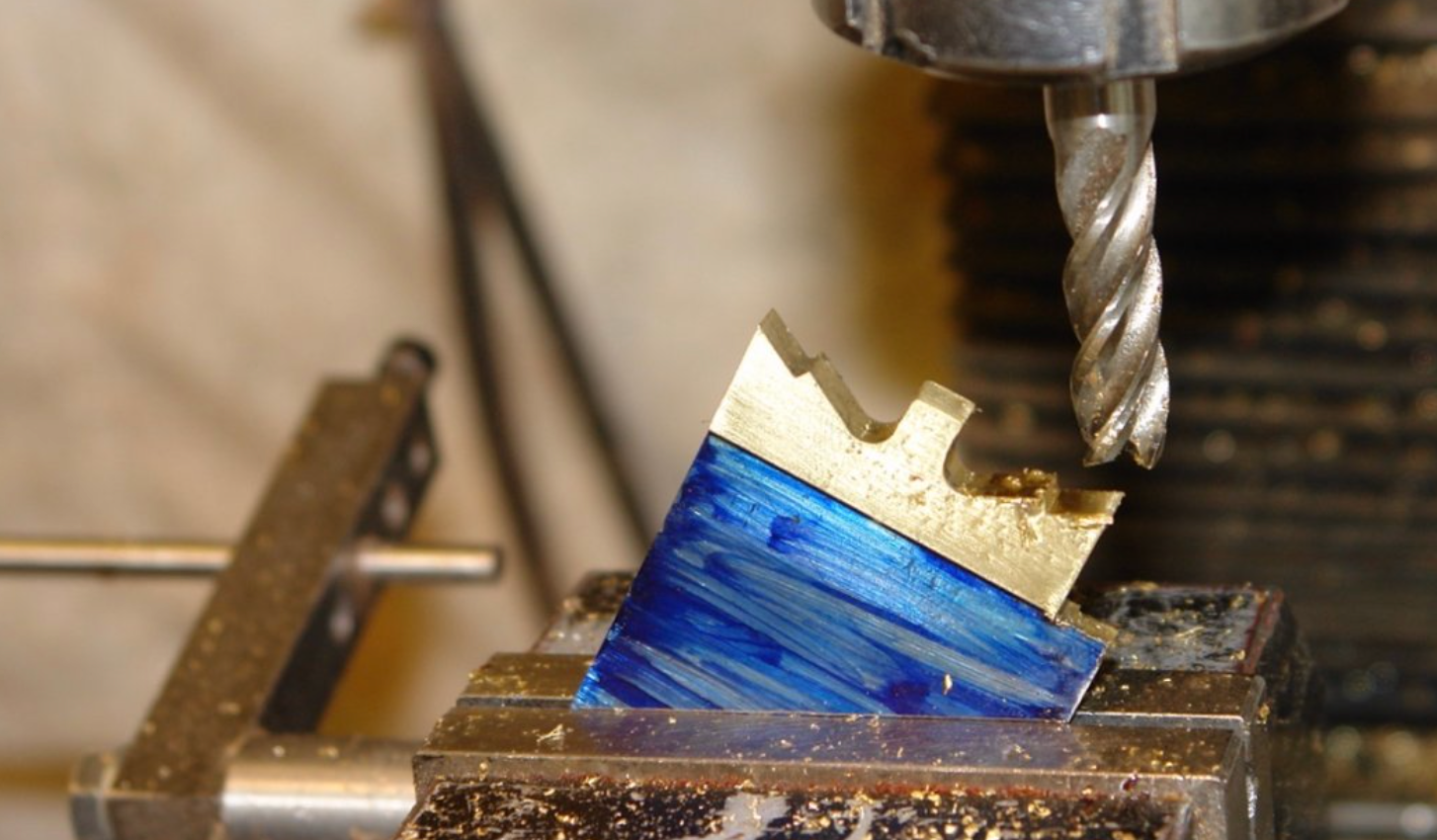
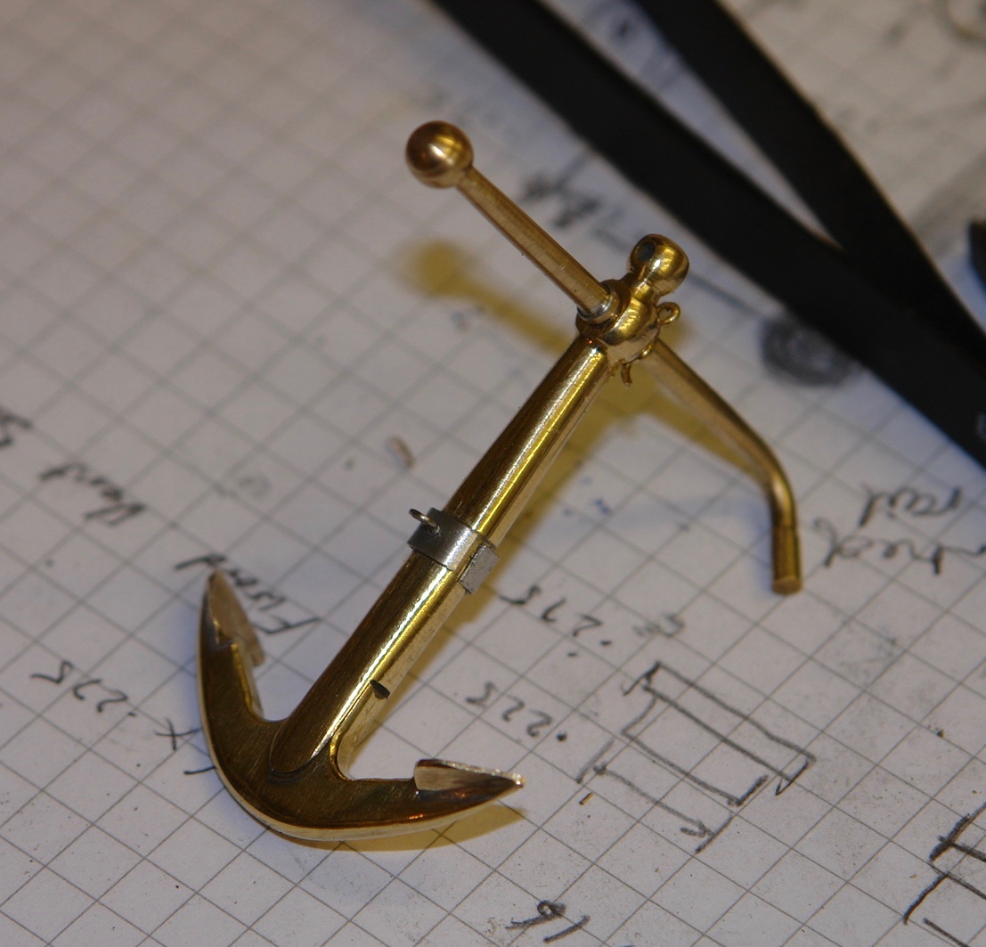
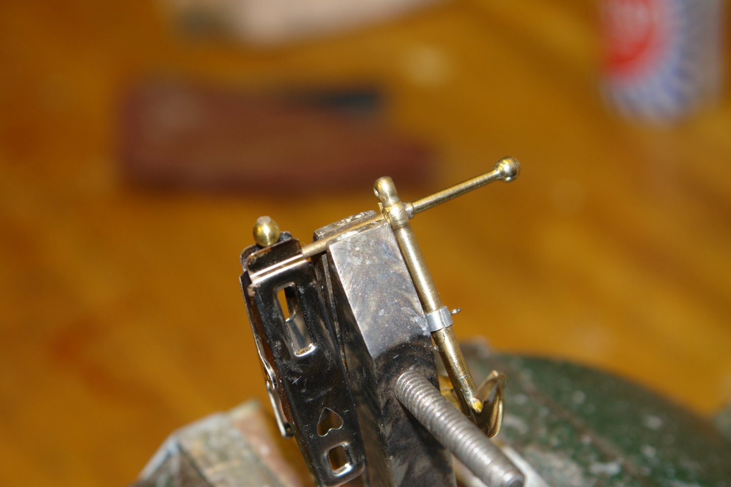
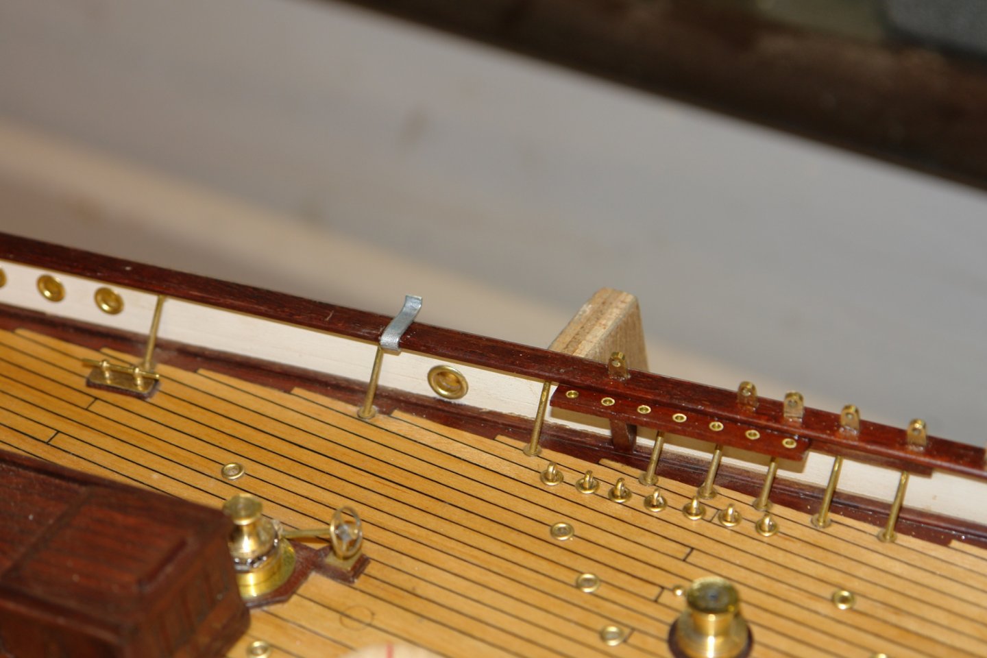
I have continued working on the pair of anchors. That wasn't quite true. On photos the shank of the anchor appears to be thicker than the crown so I needed to make it out of thicker material. Producing the crown with only a short stub also gave me access to machine the upper edge of the arms. Obviously a longer shank would have interfered with the milling cutter I started to form the shank from 1/4" round bar, Firstly by cutting a slot before milling 2 flats. In my alternative reality it made sense to form the shank in two parts (upper and lower section). I wonder why I did that? Before parting off the lower half I bored an axial hole to take a spigot for the top half. The upper shank is a flattened taper (turned and milled). The spigot was then turned to fit into the lower half and the top of the shaft was then parted off. The upper and lower shafts were then soldered together - followed by a bit of shaping with a file and emery board before joining the shaft to the crown. The brackets to support the anchors on the rail started life as an expensive gadget (never throw anything useful away). I made the balancing band out of tube with a wire lifting eye, It covers the upper and lower shaft joint as planned (at least that's my story and i'm sticking to it). Next job - the stock.


-
Great explanation JD. Worrying news about Covid. I hope that you all made a speedy recovery.
-
All up to your usual high standardised Kees. Tough news about the care center but at least you have the comfort of knowing you helped. Good that you have been vaccinated, stay well.
- 193 replies
-
- 2
-
-
- wilhelmina vii
- fishing
- (and 1 more)
-
A nice start Bill. I look forward to seeing how she progresses.
-
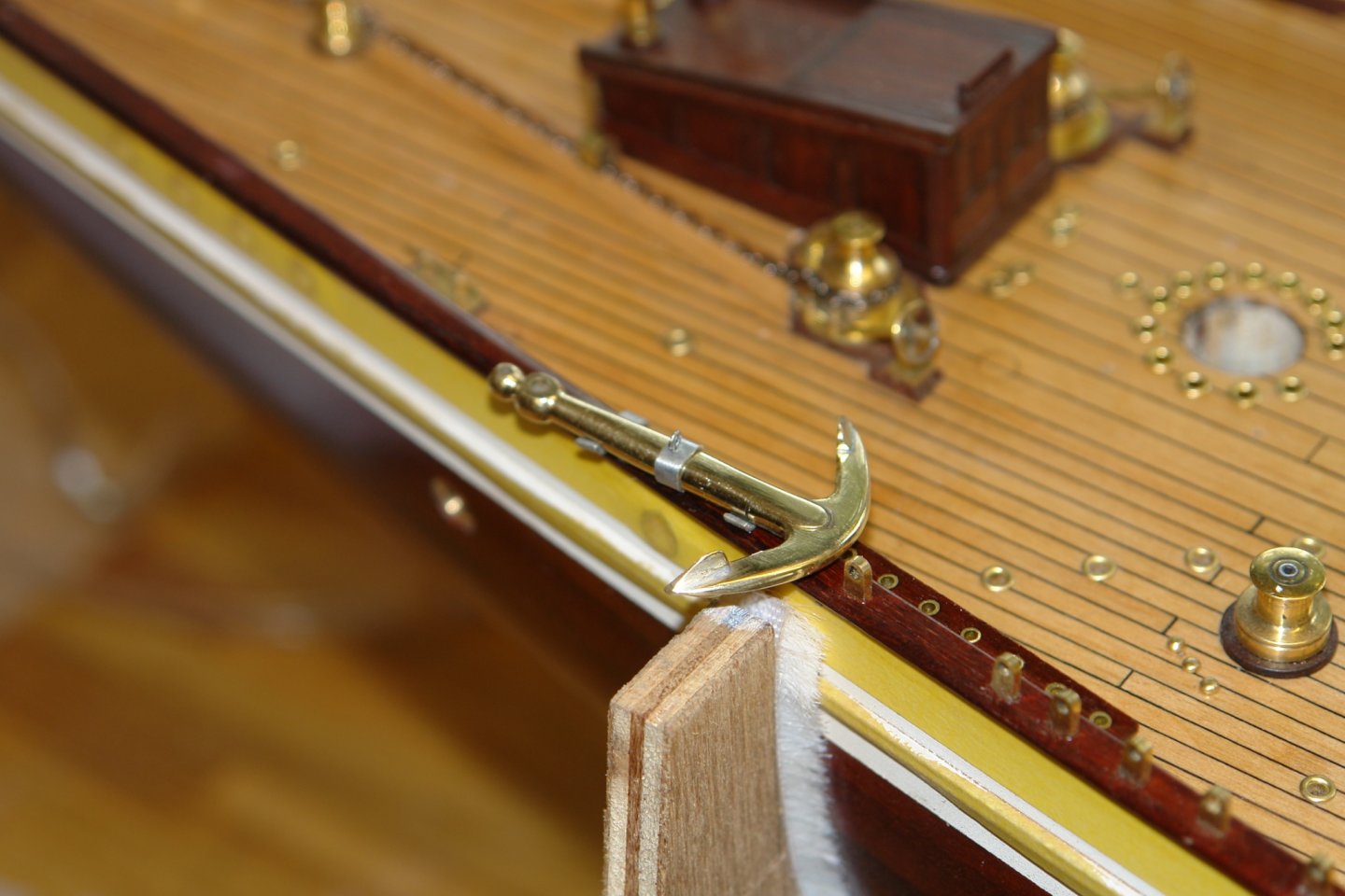
Eberhard - The anchor looks even better in situ. Photos do seem to magnify construction dust very well.
-
Sorry Guys, I'm not scheduled to get my first inoculation until late February so you won't let me in. Thank you Steve and Pat, and thanks to everyone for the likes.
-
Keith. We have a tradition of passing on such things to the next generation. We had one to pass on to the grand daughter at Christmas. Un fortunately Mr Covid kept her away, Roll on next Christmas. Neat job on the hand pump by the way.
-
Tom, I quite like the way parallel planks notch in to the deck edge plank.