KeithAug
-
Posts
3,986 -
Joined
-
Last visited
Content Type
Profiles
Forums
Gallery
Events
Everything posted by KeithAug
-
 Yes I have been following the market developments. I think a high quality inexpensive machine is several years away.
 -
Thank you Eberhard. I had been thinking of trying for the very reason you identify. However I don't think that I will use it a lot and newer technologies might come to my rescue first. I am waiting for good quality 3D printing to become more affordable.
-
Plenty of scope for your imagination Tom, should be fun.
-
A fascinating project, I bet few vessel match her for lack of aesthetic appeal. I will watch with interest.
-
Keith - I particularly like the way the crew have dug into the coal but feel they will need to repaint he deck white when they get a chance.
-
Druxey - My wife has a long list. Allan, I just used the bynes saw with a fine toothed slitting saw blade (108 teeth x 3" diameter). I have blades that I reserve for cutting metal and ones which I only use on wood. As for cooking I can do most things to a modest standard but I am the go to member of the household when it comes to curry's with all the trimmings.
-
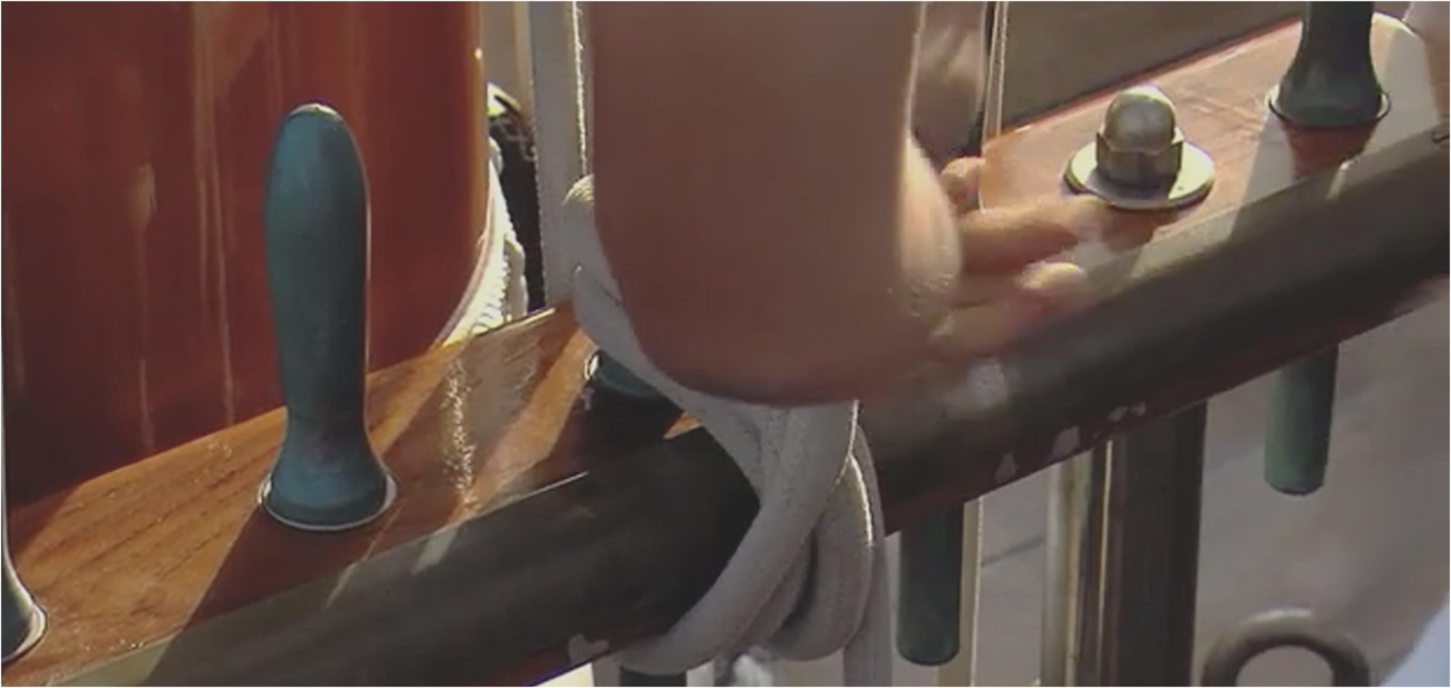
A very good point Eberhard and I suspect the designer agreed with you. The picture below is one of the later pictures I have of Germania which clearly shows the hex nut albeit with a domed end. You will also notice the brass rubbing strip on then rail edge. However here is an earlier shot with the rail in the "as built" state with no nut and with no rubbing strip. I suspect that at some stage the original design proved a bit fragile and this led to the modifications. I made the nut too large so I may lop it off and revert to the original design. No one is ever going to notice the cheat. Sometimes life needs to be a bit easier.

-
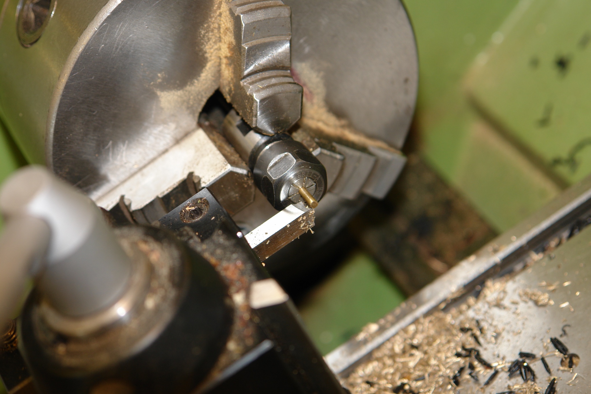
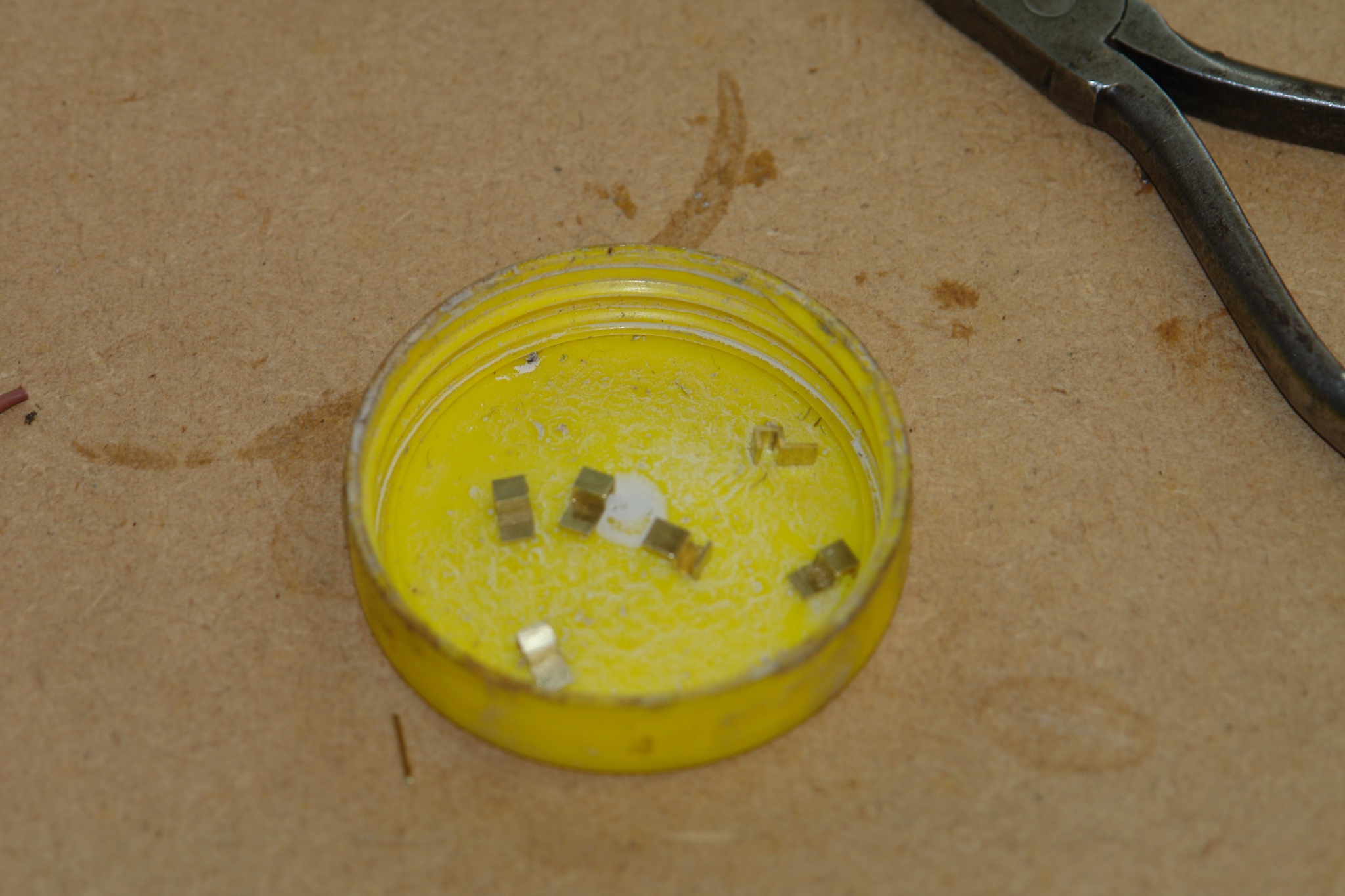
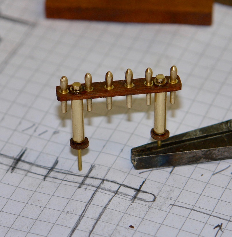
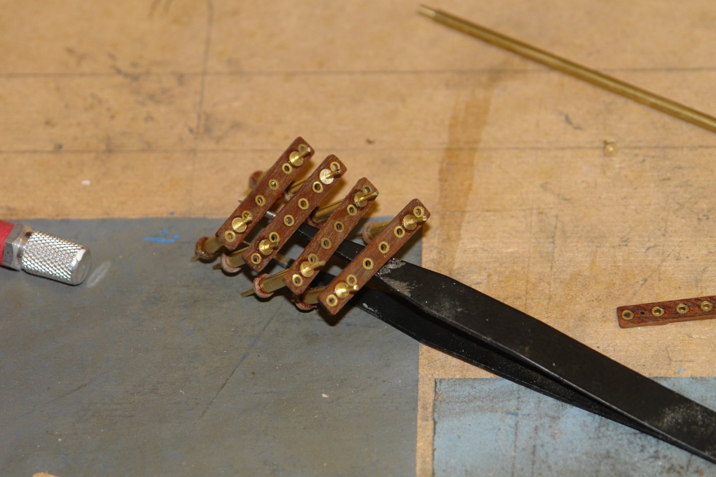
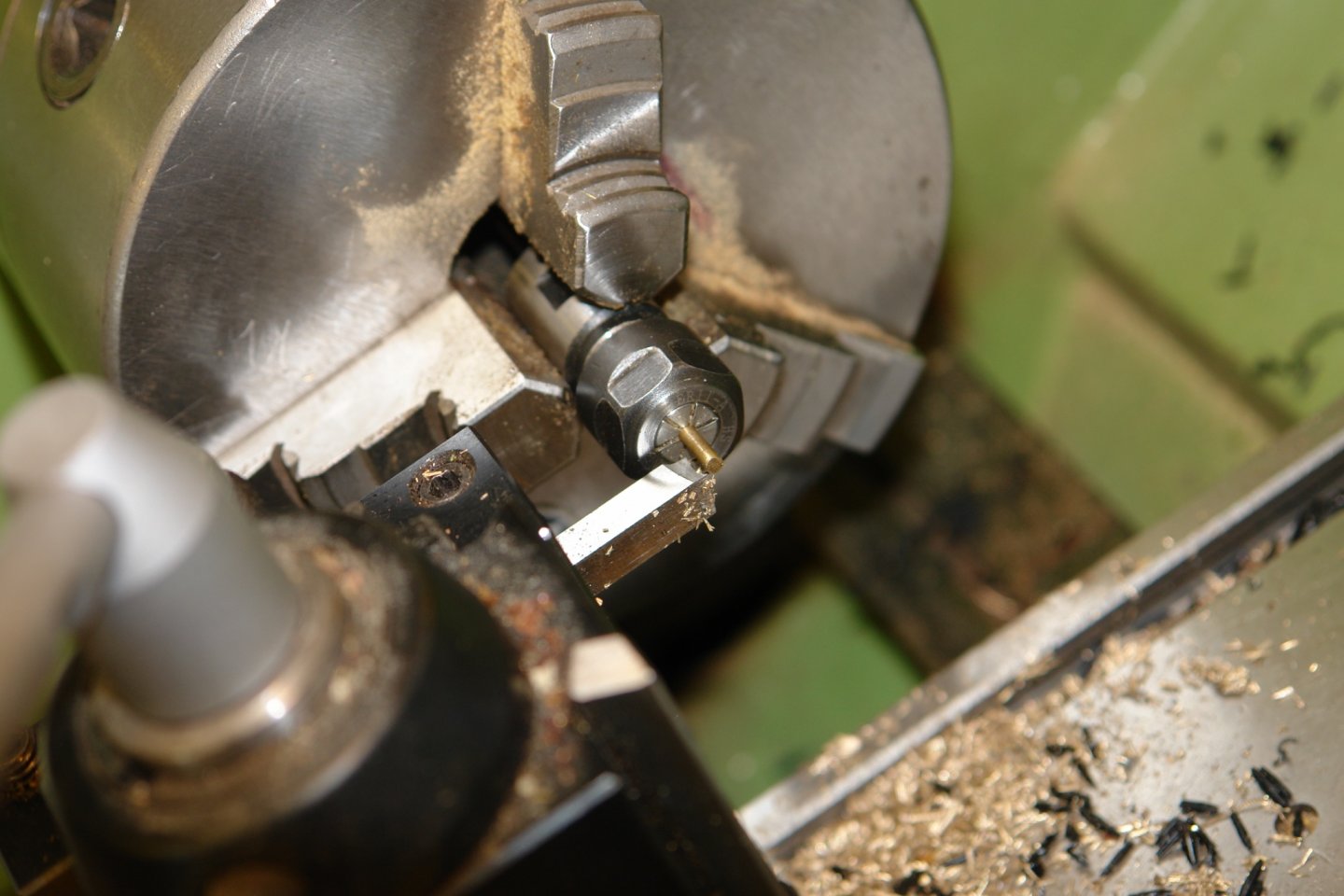
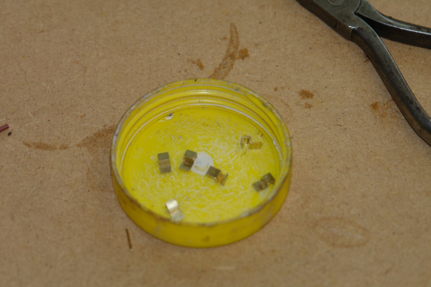
Thank you Keith. Dinner is delayed so I will finish the post. I machined flats on a 3/32" rod to form a hexagon and then parted off 8 retaining nuts. These were glued in place and then the pins were inserted into the rail.
-
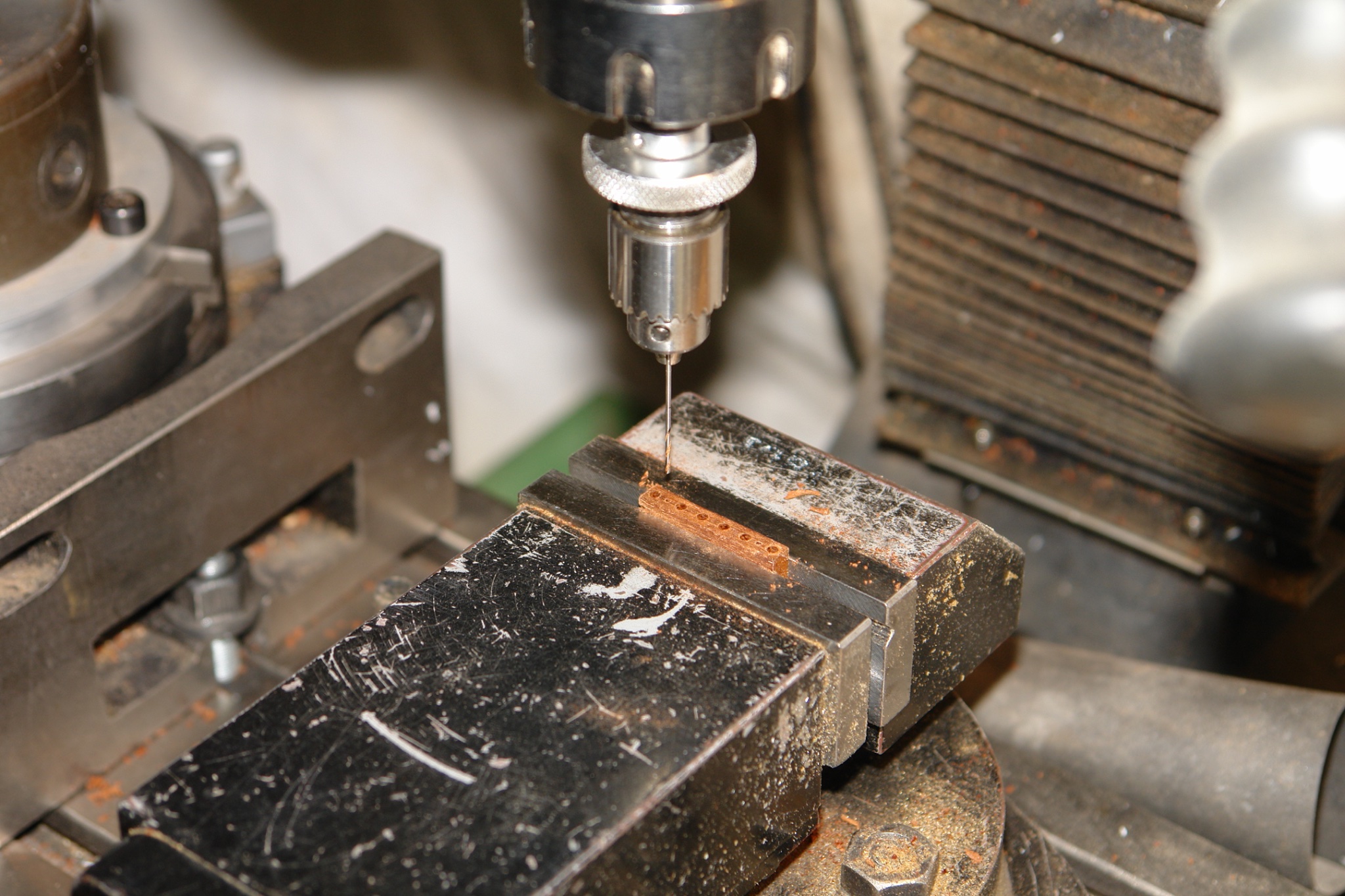
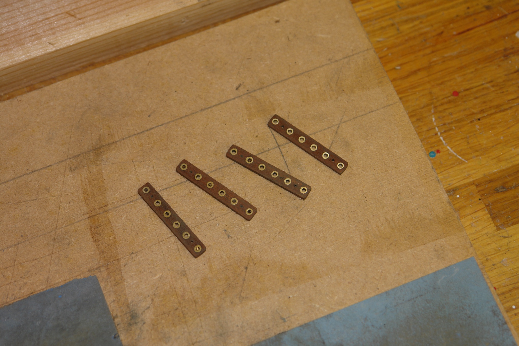
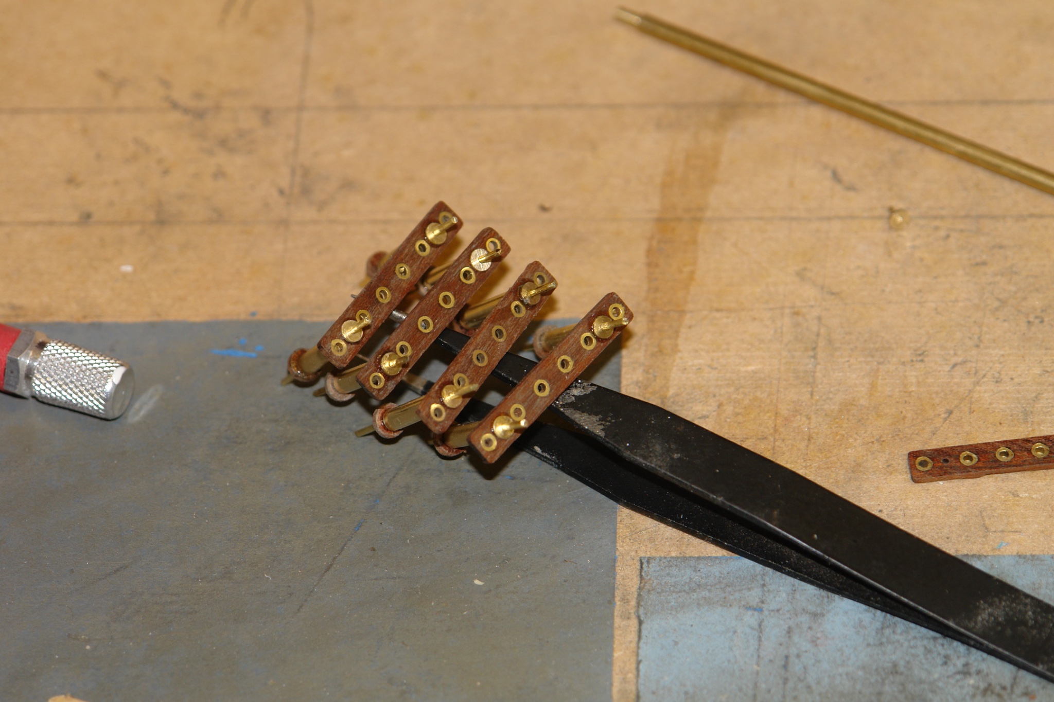
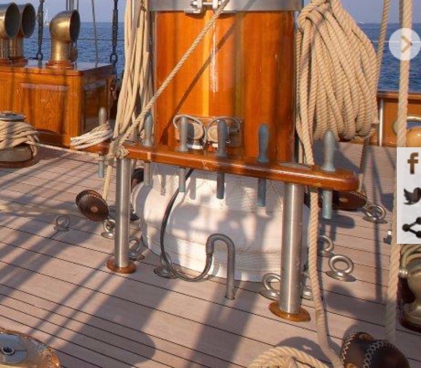
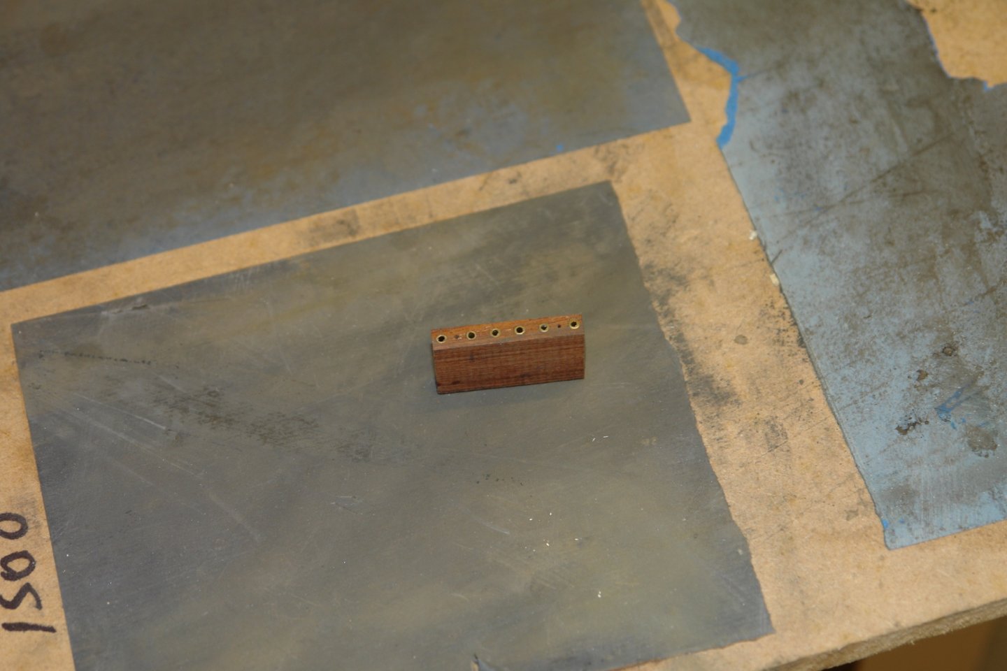
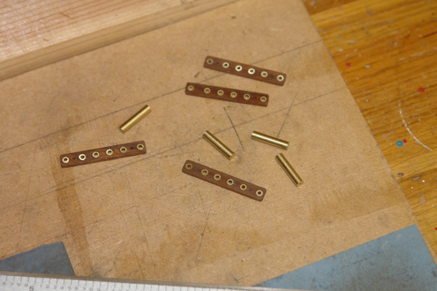
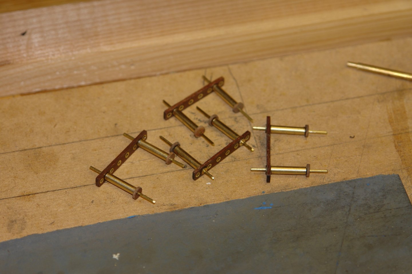
Time for another update. I hope you are all well and that your Christmas won't be too disrupted by the pandemic. Pat - thank you for your comments. So I moved on to something different. On each side of the fore and main masts are a pair of pin rails - 4 in all, and all identical. I have fairly decent photos. I was able to scale the dimensions from a combination of photos and a little plan detail. As usual I made a sketch. Each rail has 8 holes - 6 for pins and 2 for the legs. The rail height is 0.6" and they are 1.25" long. I started with a block of mahogany which I cut to size and then I drilled the 8 holes. The pins will fit in brass collars .04" internal diameter and .092" outside diameter. I pressed and glued 6 pieces of brass tube into the mahogany to create the collars. I then sliced off the 4 rails. The legs were turned from brass rod 1/8" diameter. The legs were bored to take spigots ( at both ends) for mounting to the deck and attaching the rail. I also turned up some small mahogany plinths before assembling the various bits. I also turned the brass washers which fit over the upper spigots and below the retaining nuts. I ground a piece of 1/4" tool steel into the profile of the belaying pin handled then started manufacturing the 24 pins. They were turned from 3/32" rod. I am on cooking duty tonight so I must stop here. More to follow shortly.


-
Dan, I fear this build will be over much too quickly.
- 33 replies
-
- 4
-

-
- James B Colgate
- whaleback
- (and 2 more)
-
I have wondered about that tool for a while, but never taken the plunge. I’ll be interested to see how it works out.
-
Allan, your experience with silkspan (paper) will be quite informative when I come to make sails for Germania. I am watching with interest but as you progress I would welcome your view on how applicable it is for much larger sails.
-
Tim - Yes, your attention to detail is better than mine. I will now have to rectify matters.
-
On retirement I promised myself that I wasn't going to embark on any project that would become a chore. I am now in retirement year 8 and despite a number of close shaves to date i have not failed.
-
Tim - I don't believe so. I'm pretty sure that the ventilators are turned individually and manually by the crew.
-
Allan, so did I. I remember converting to silk after the frustration of tissue which seemed to puncture on every landing. I’m assuming silkspan lies somewhere between the two in terms of robustness.
-
Very interesting Allan. Do you worry about the fragility of the silkspan during construction or is it reasonably robust?
-
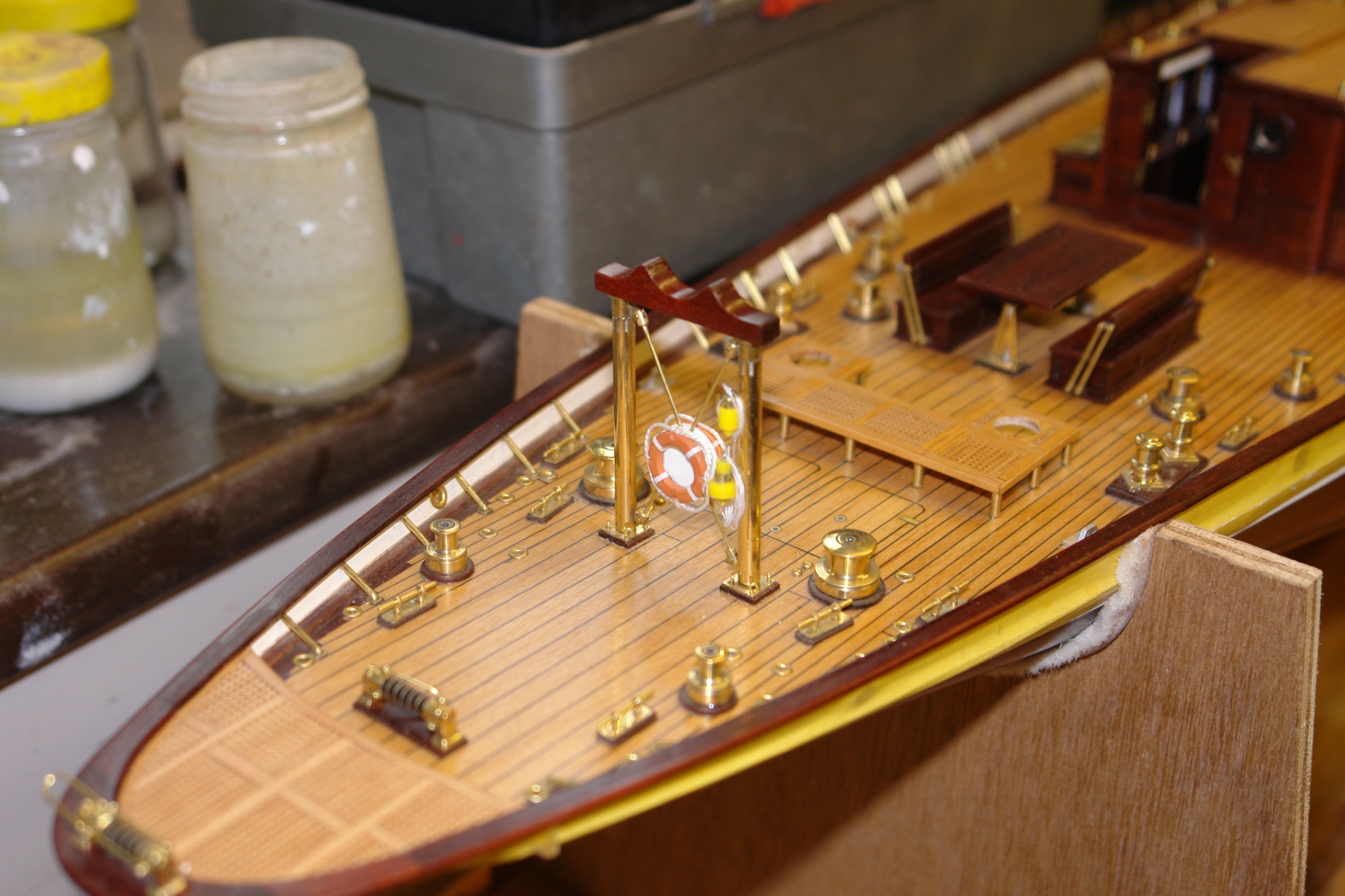
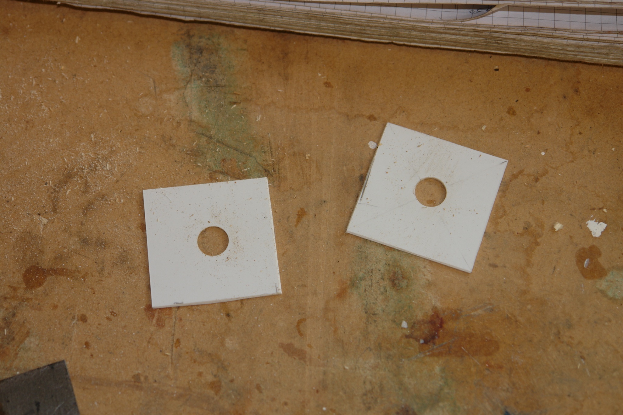
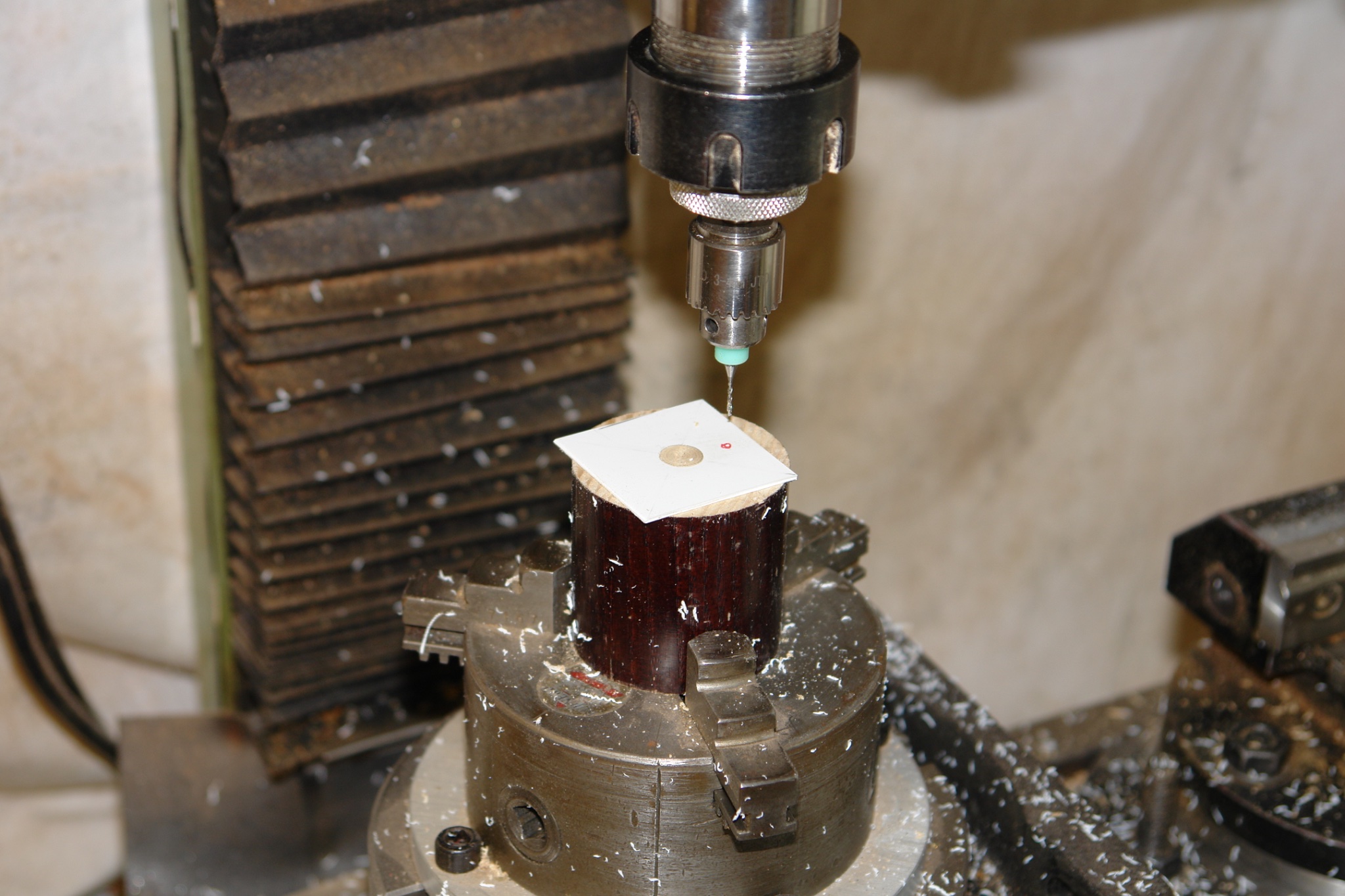
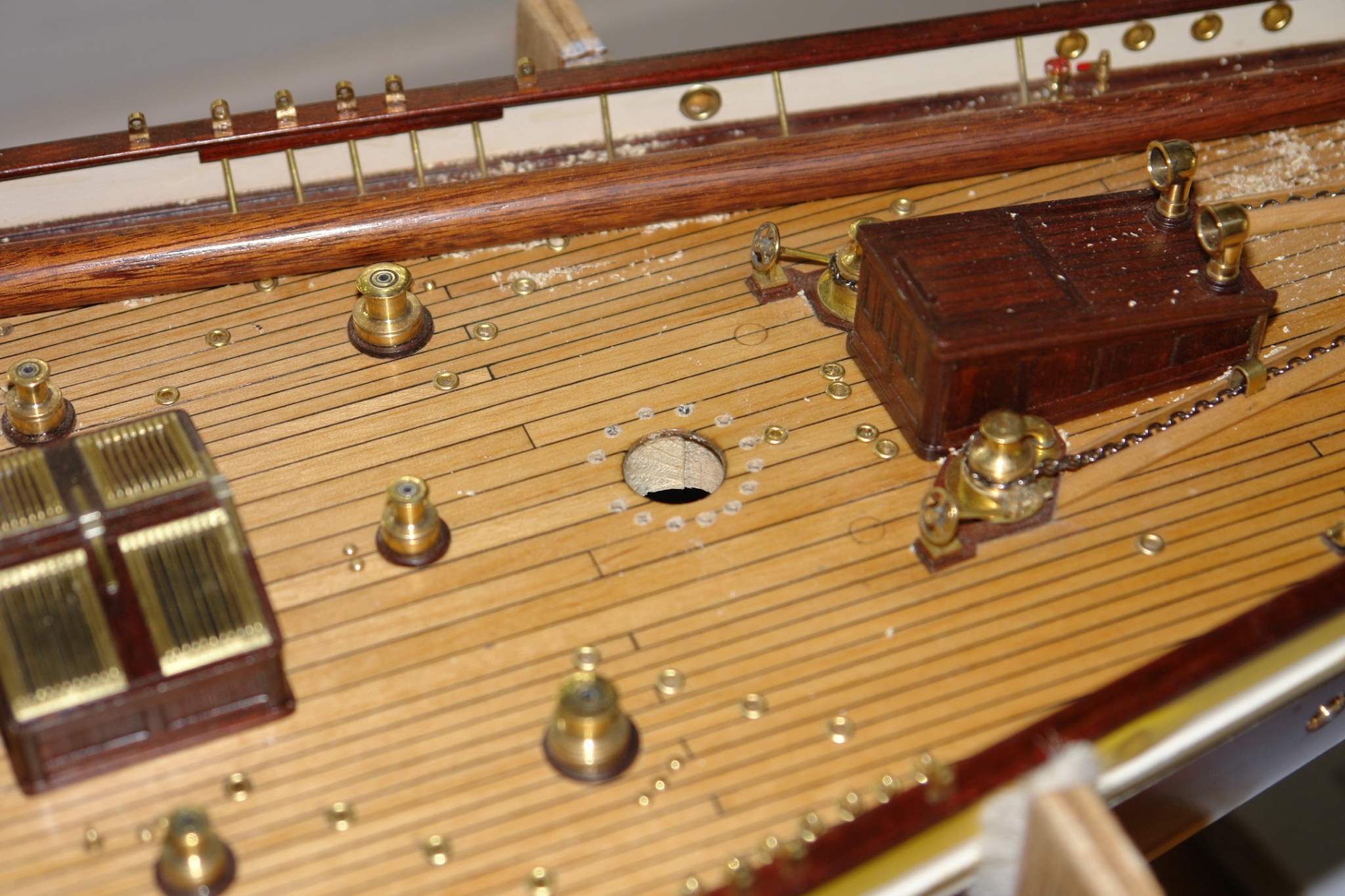
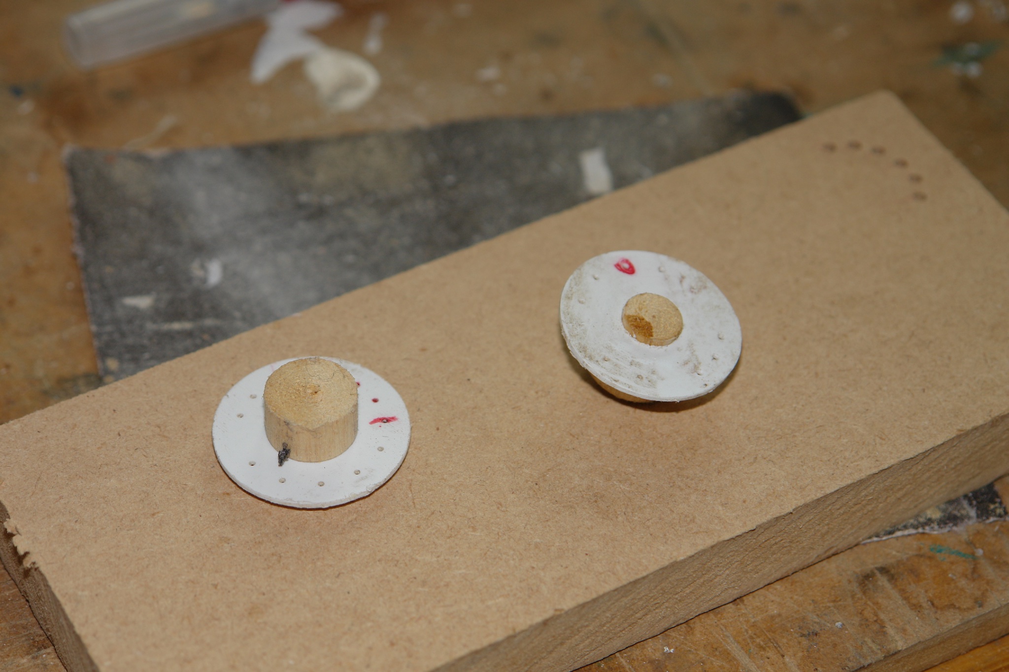
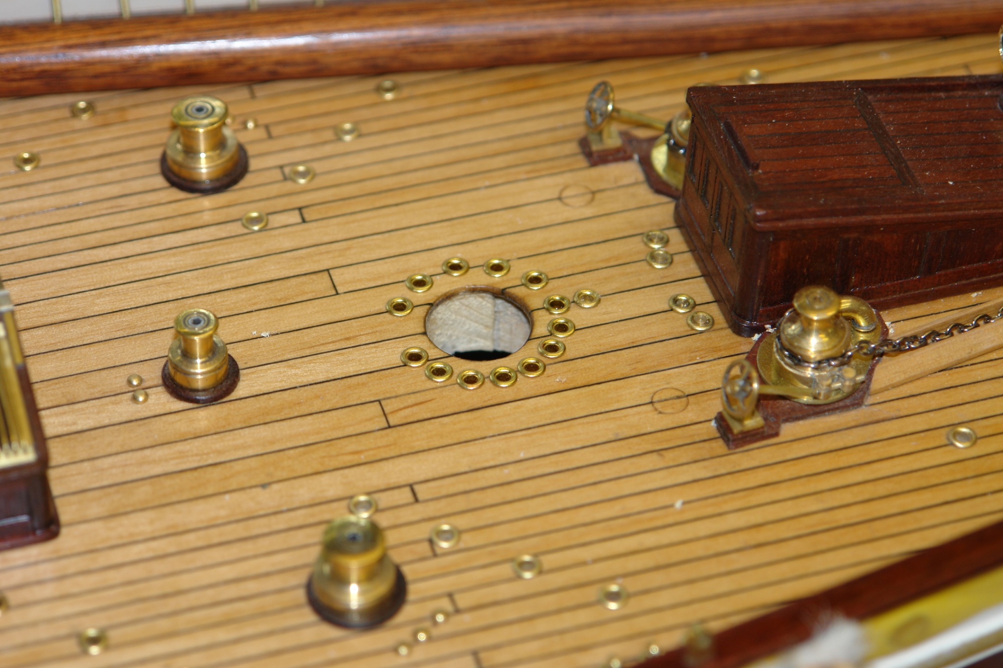
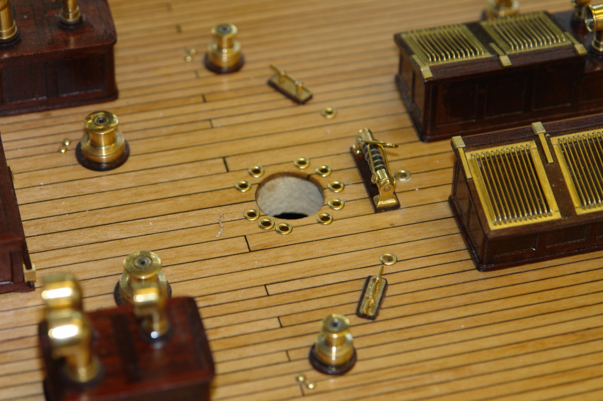
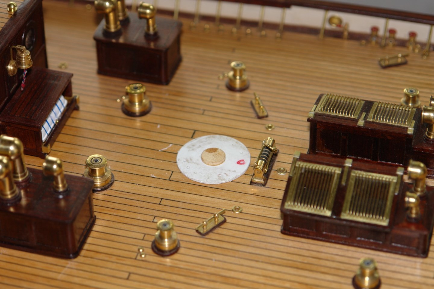
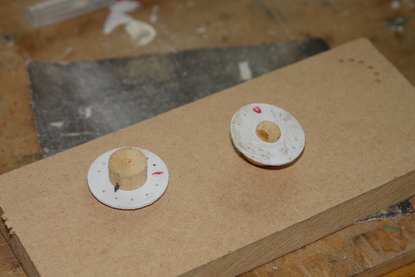
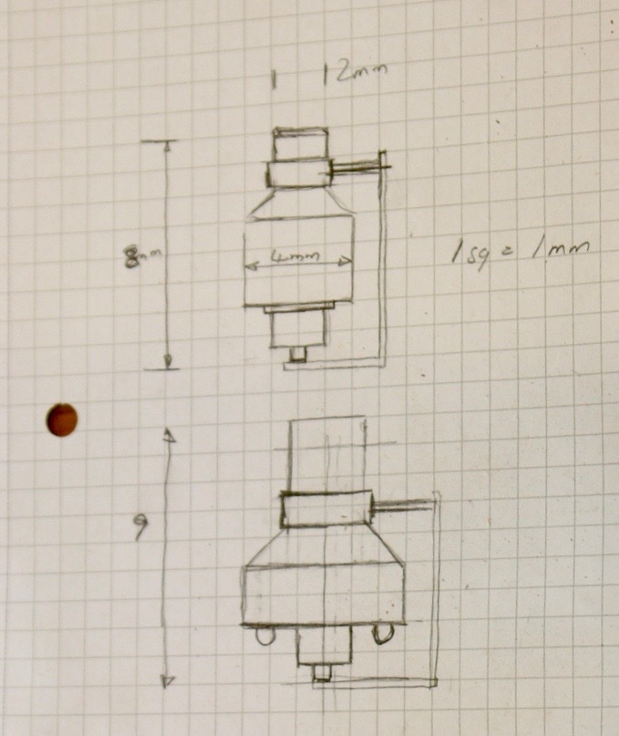
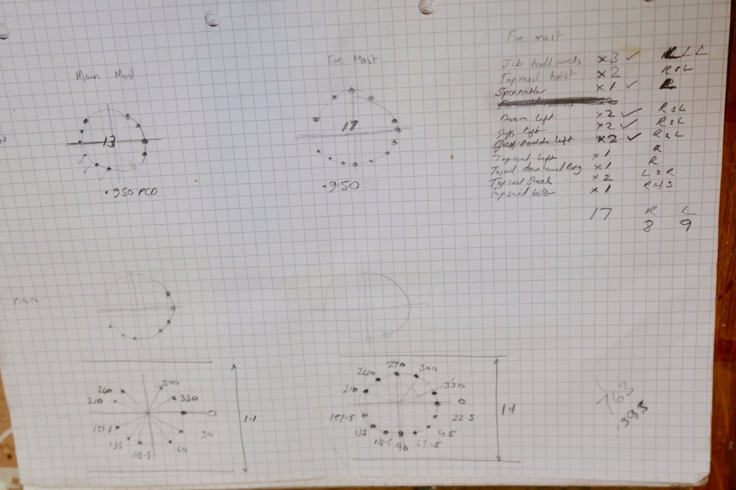
Pat, Druxey, Keith and Dan - thank you for the comments, you are too kind. I am gradually grinding my way through stuff that I left incomplete some time ago. The main boom crutch was almost finished minus the life ring lights. I find myself flipping into mm dimensions at times - catching up with metrification which I seem to remember happened about 40 yeas ago. I must have some sort of regressive Luddite gene. I turned the lights from yellow plastic rod so I didn't need to bother with painting. I attached a length of line and tied them to the life rings and then mounted them on predrilled holes in the crutch ( sometimes planning ahead works out ). My regular readers will note I still haven't sorted out the unnatural lie of the rope around the life rings - it is still on the "to do" list. For an age I have been putting off drilling the holes around the base of the main and fore masts (to take blocks). This is not through some unnatural aversion to the drill but rather because the plans and the photographs don't match. I spent a lot of time trying to reconcile and record the differences while thinking trough what rigging lines would go to which blocks. In the end none of the evidence was very helpful so I decided to go with my best guess. Having made a guess I then went to a lot of trouble to position the holes very accurately. Accurately positioning the location of guessed holes must be one of the definitions of madness. But anyway I cut templates from placard. These were accurately drilled with holes at the pitch circle diameter extracted from the plan and at angular spacings plucked from fresh air. These templates were then mounted on turned spigots that fitted the mast holes in the hull. The block mounting holes were then drilled through, note the wood chips everywhere. Finally brass grommets were glued in to take the pre made eyelets. In the coming months as I proceed to rigging I will no doubt discover the error of my ways.


-
Hello Tim, I see you are gradually working your way through my various posts, Thank you for taking an interest and for the the detailed feedback. Someone did suggest this but finding the time would be an issue and I think I prefer building rather than writing. I am thankful for those of you who take an interest in what I do but I fear not many outside the forum would find my ramblings of great interest. Maybe the book will have to wait until I am too feeble to do much else. Tim - I hadn't seen this before but on your prompting I did a bit of youtube research. It looks like a very good Idea which I plan to try out. Thank you for the advice. Thanks for the link Tim.
-
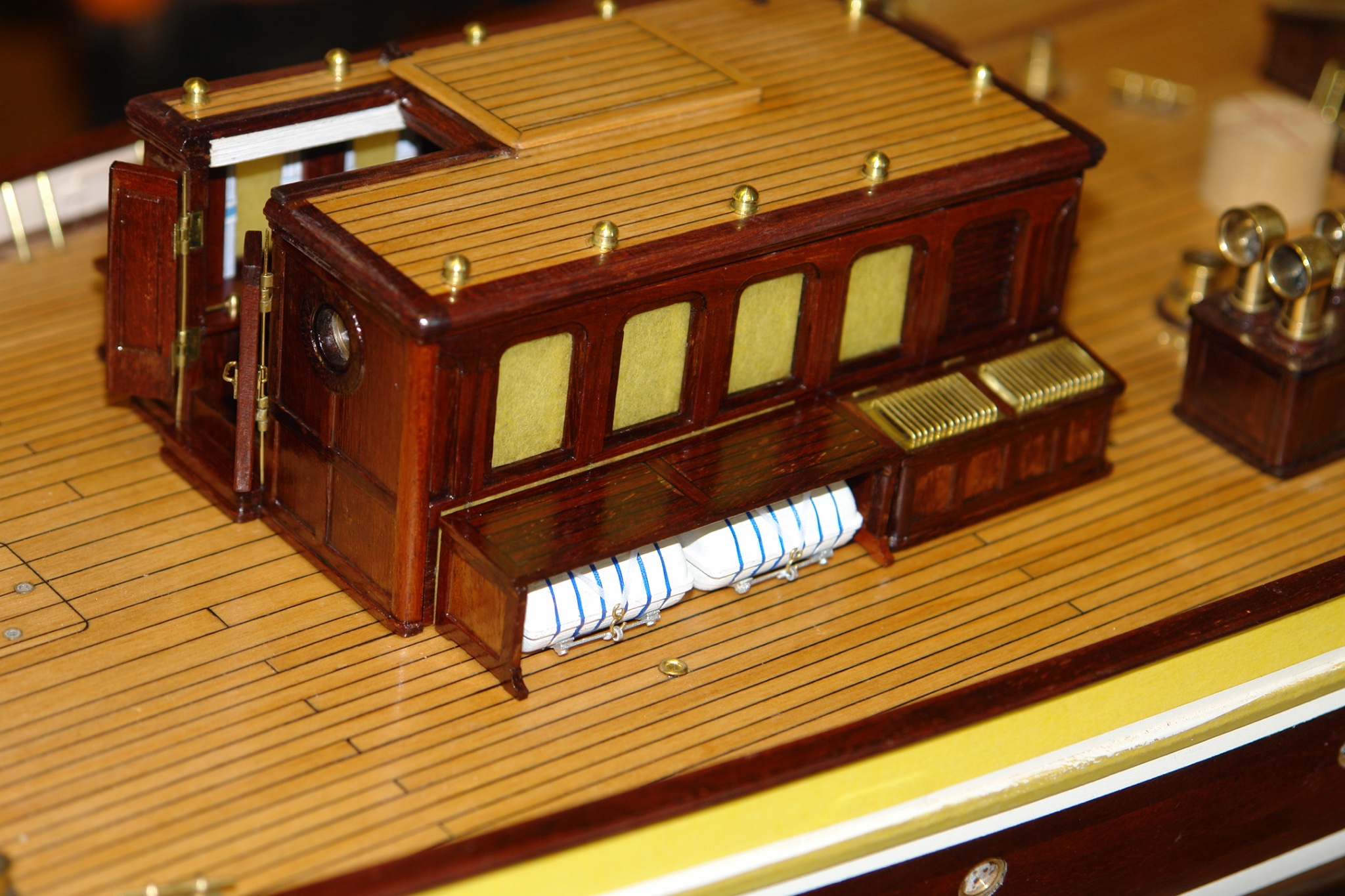
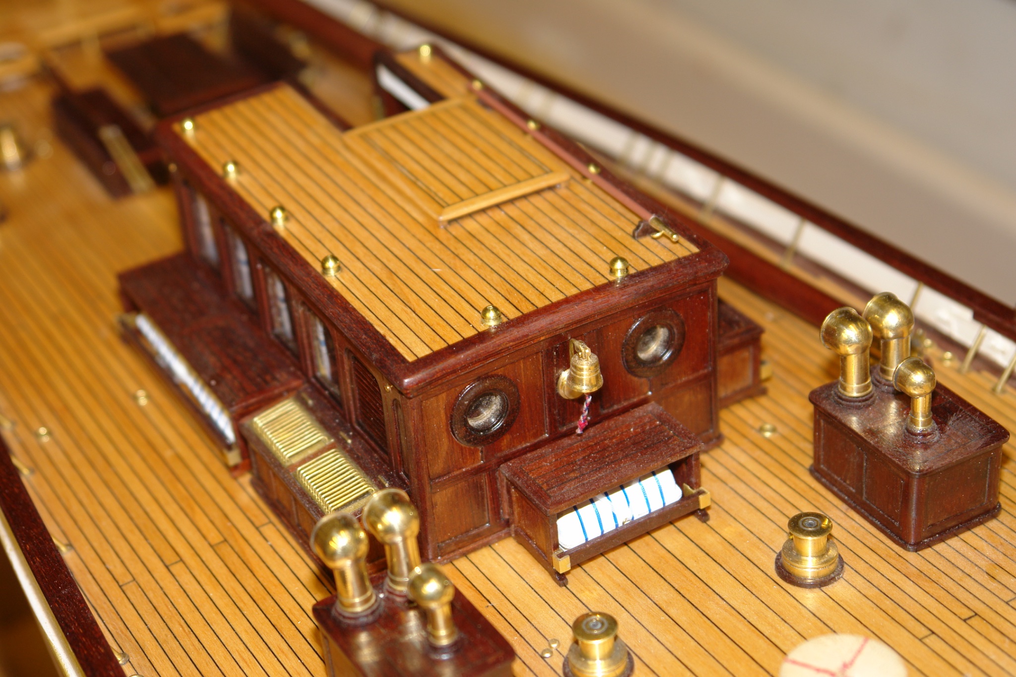
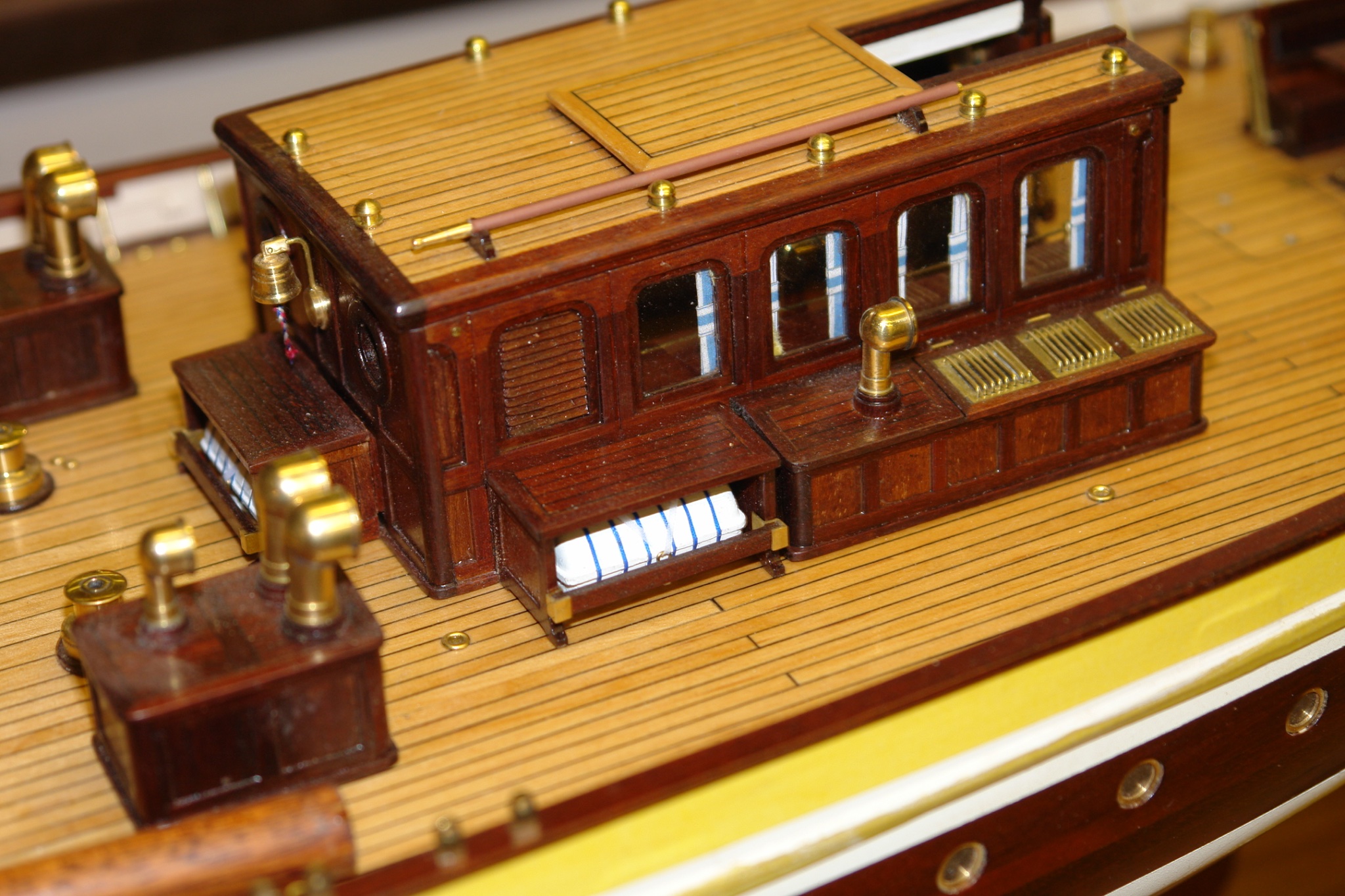
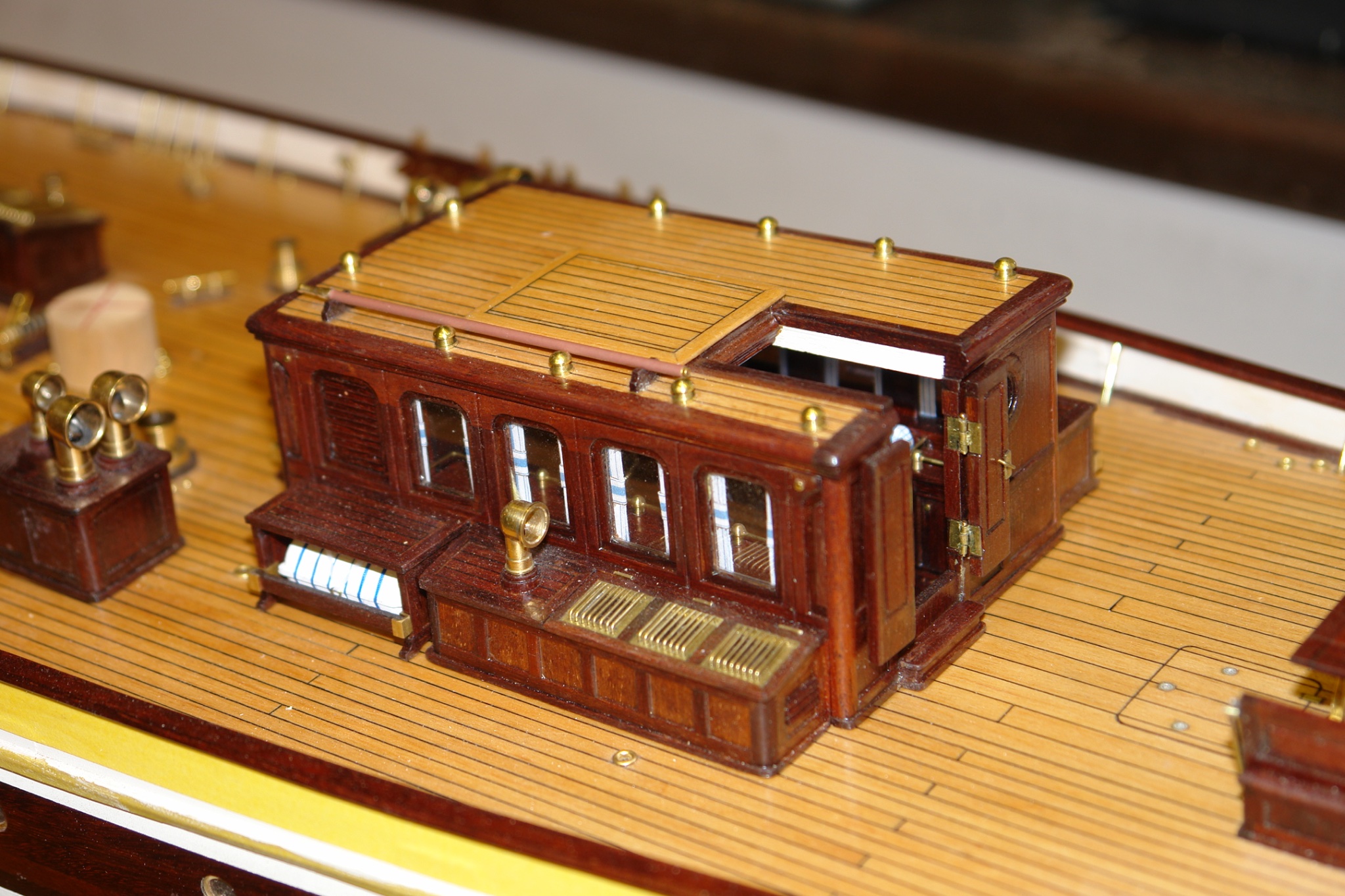
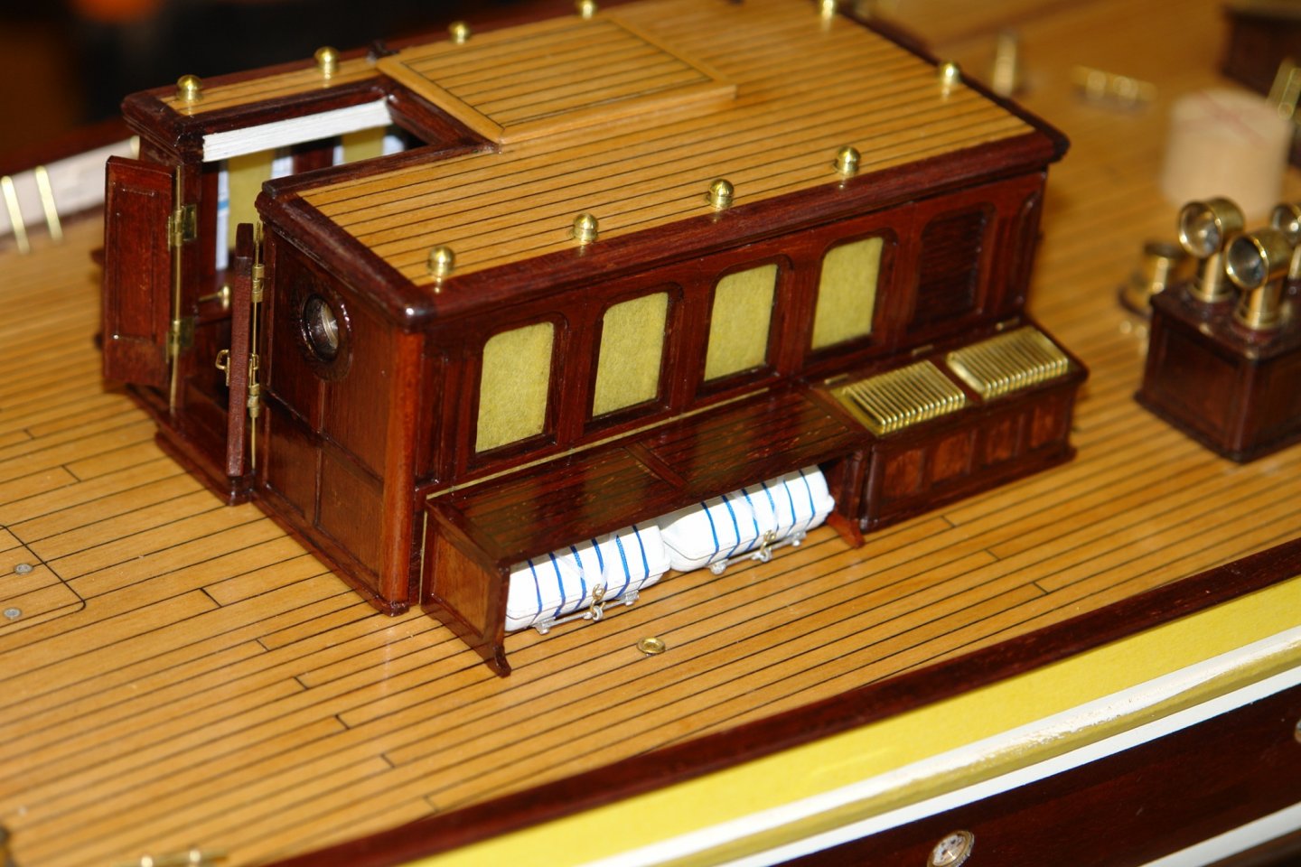
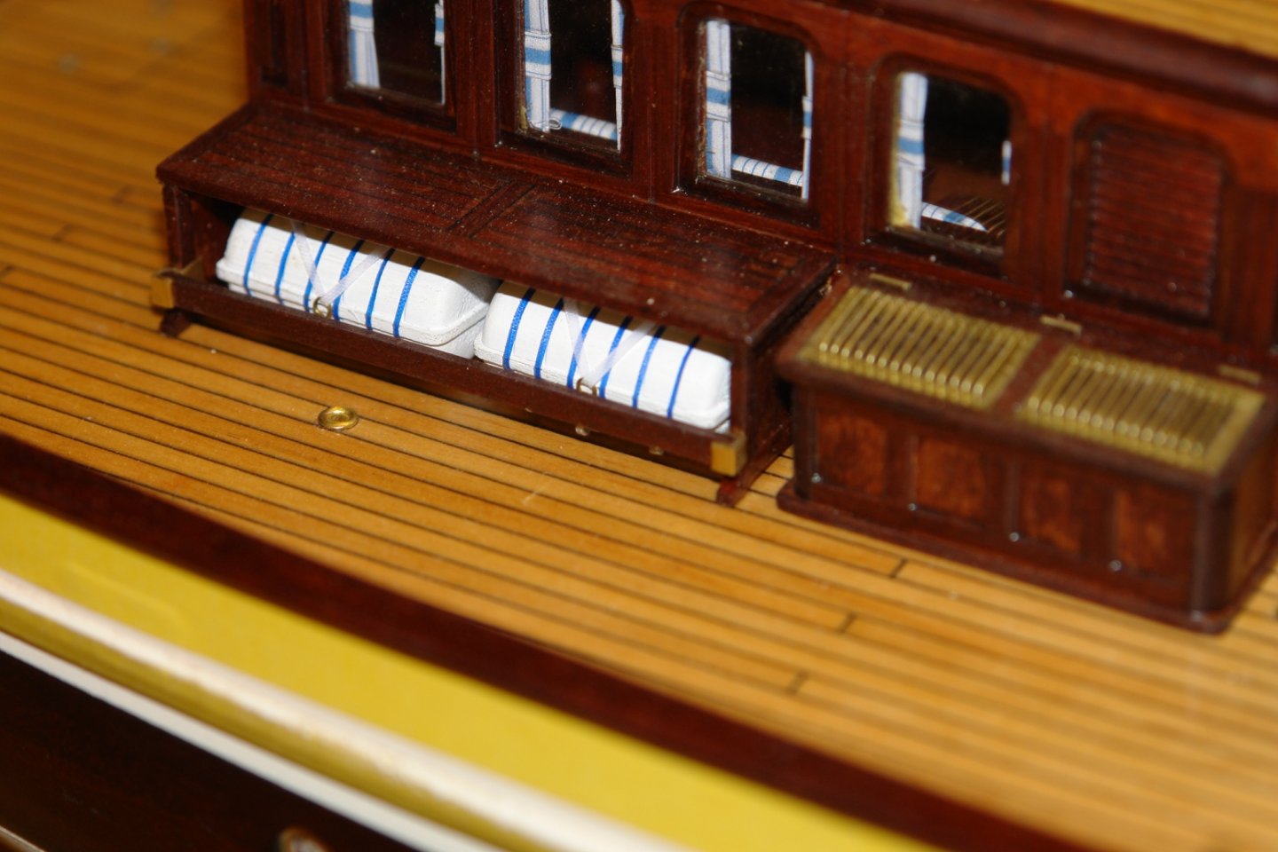
Allan, Keith Druxey. Pat and Gary- thank you all for your comments, you are all too kind. I quite often look at other modellers work and think I wish I was that good. Perhaps it is all a matter of perspective. Not much of an update this time - just to confirm that I finished the deckhouse and can now move on to something else. The benches were glued in place and the life rafts were glued beneath them. I then made the brackets for the planks that fit across the front of the rafts. The planks were then installed making the raft cradles almost impossible to see from most angles of observation. With the poly application finished I was able to remove the masking tape from the windows. The ships bell was mounted. The penultimate vent was then put in place. The wires holding the doors on were removed and replaced with hinge pins. Apart from a good dusting the deckhouse is complete and now I will have to decide where to go next.


-
Looking really good.
-
The tracks look pretty good to me Keith, I don't think many would notice the slight scale issue. Were they black on the original? I am trying to remember my last visit to HMS Warrior where I think the tracks were brass. In any event I do like the way the intersecting circles decorate and add interest to the deck.