KeithAug
-
Posts
3,986 -
Joined
-
Last visited
Content Type
Profiles
Forums
Gallery
Events
Everything posted by KeithAug
-
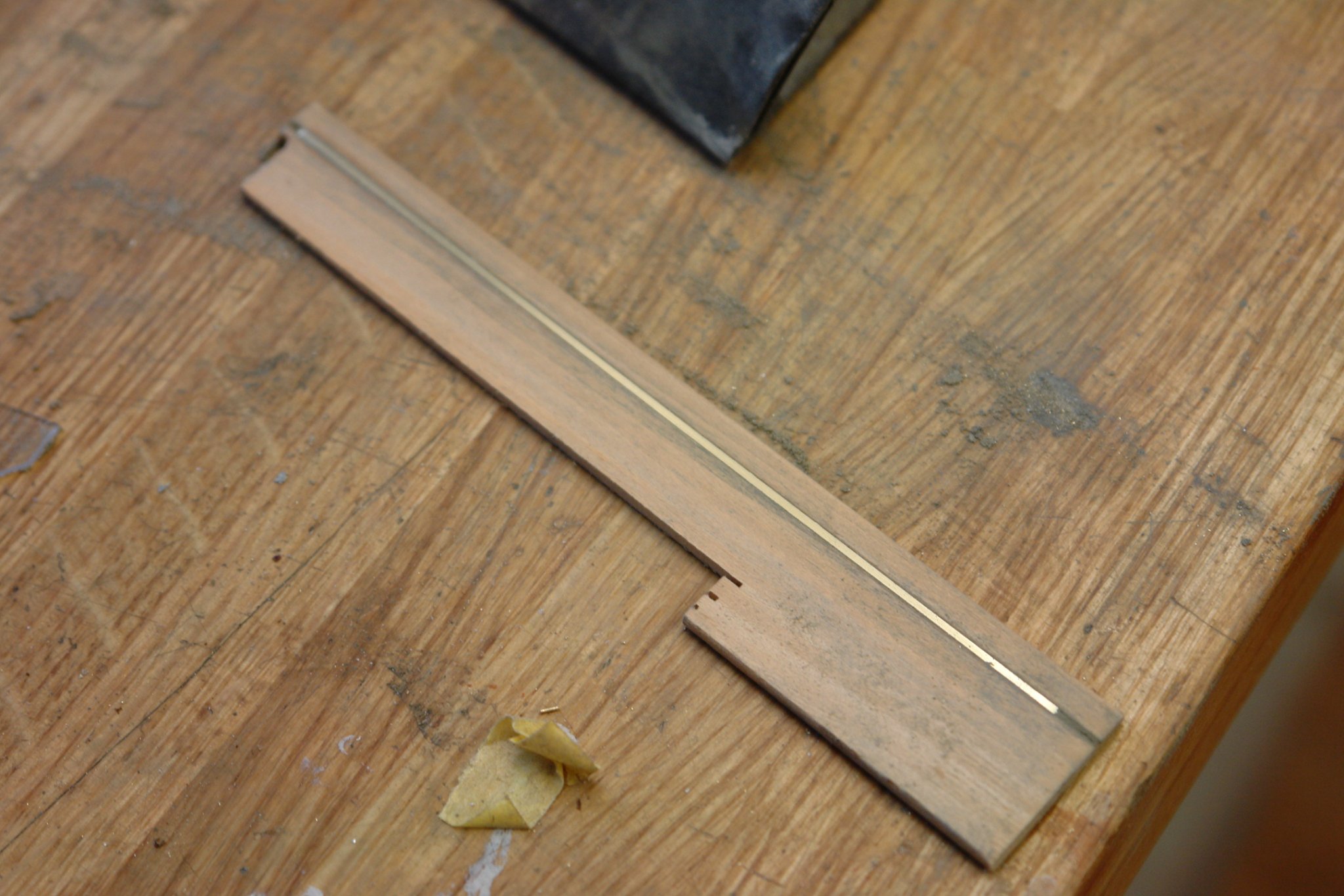
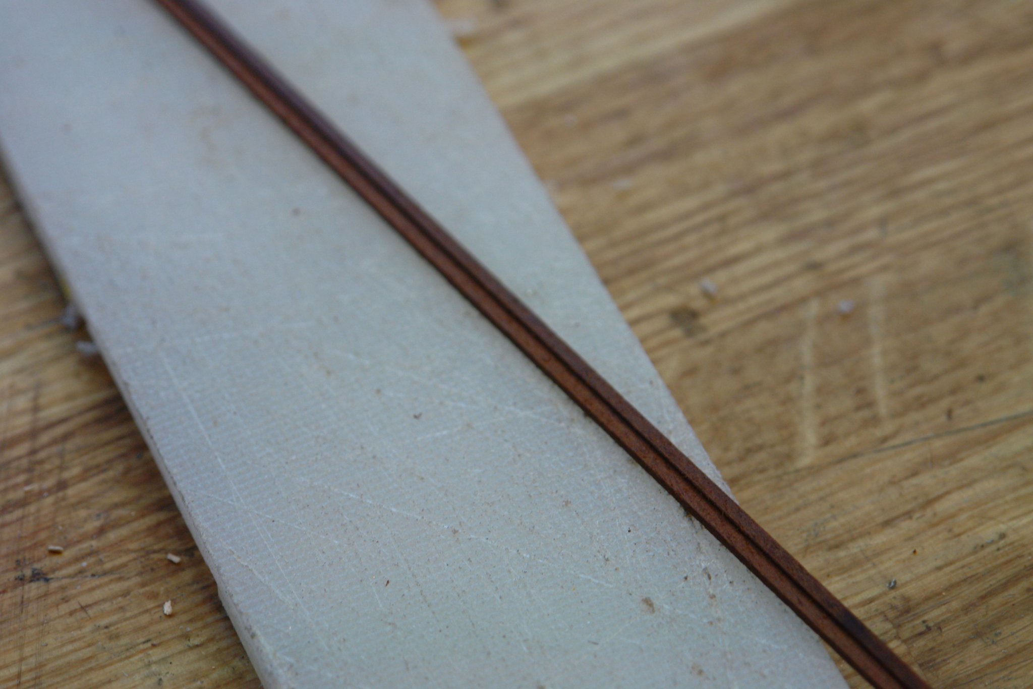
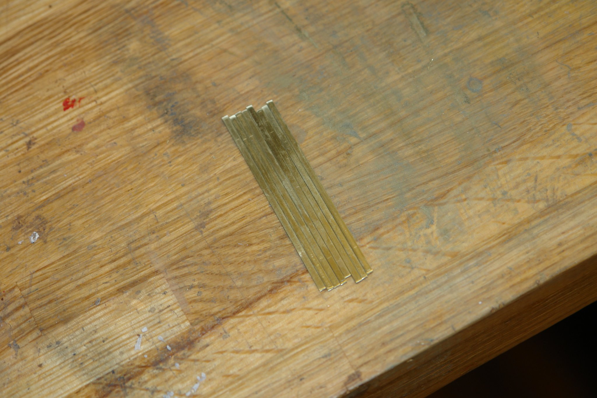
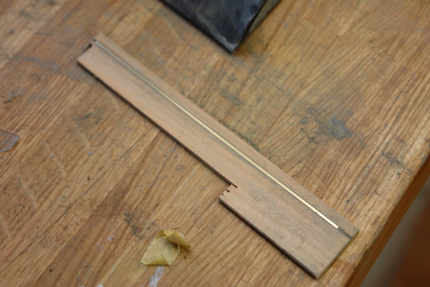
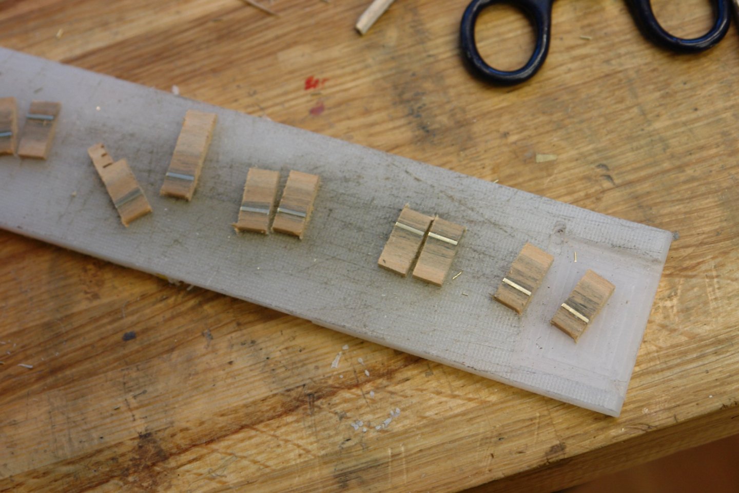
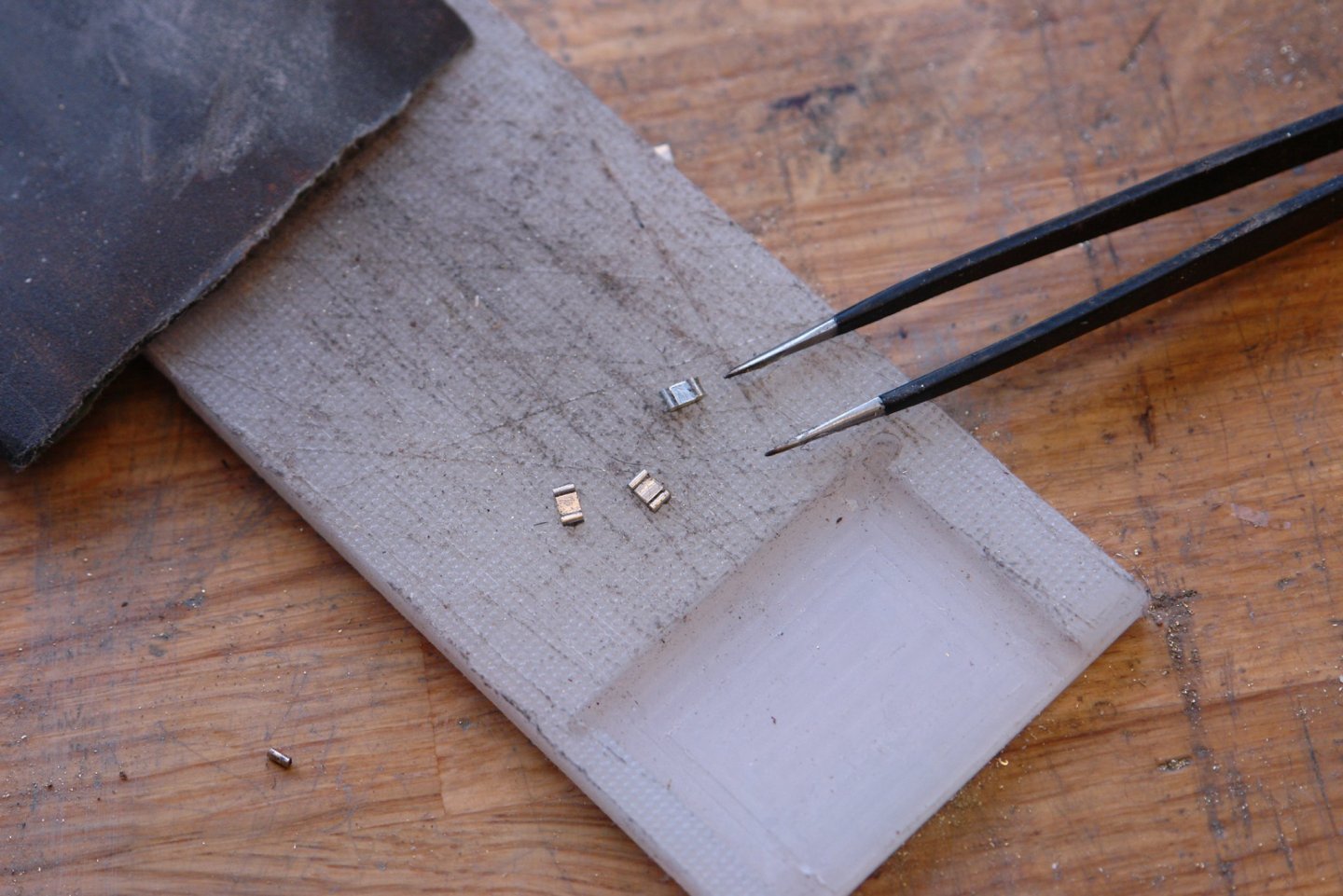
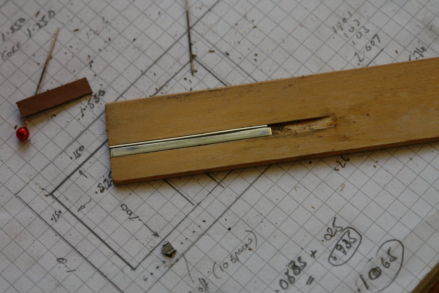
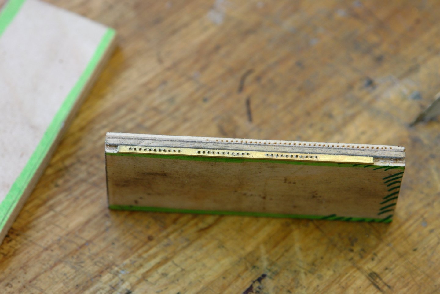
 Thank you Boris and Keith. Mark / Paul thank you for following my exploits with my carbide drill, its an old friend and I will miss it once it has gone. Today was wet so I got on with the protection bars. I also needed to make the hinge straps - these are .04" wide and i decided the best way to make them was to file flats on either side of .04" brass rod. I did this by taking a piece of wood, cutting a slot in it .03" deep and then gluing the rod in it and filing off one side. Then a second slot was cut .02" deep and the rod was flipped over and re-glued before filing off the other side. Thus producing a strip of .04"x .02". The straps were cut to length while still attached to the wood. I also made simulation hinges by soldering wire to the edge of a strip of brass and then cutting off short lengths. The simulation hinges were then glued in place. I needed to add hinges to the previously completed skylights but the hinges for these were only single sided. Once more they were cut to length and glued in place. All a bit of a fiddle but it did successfully fill a wet day.
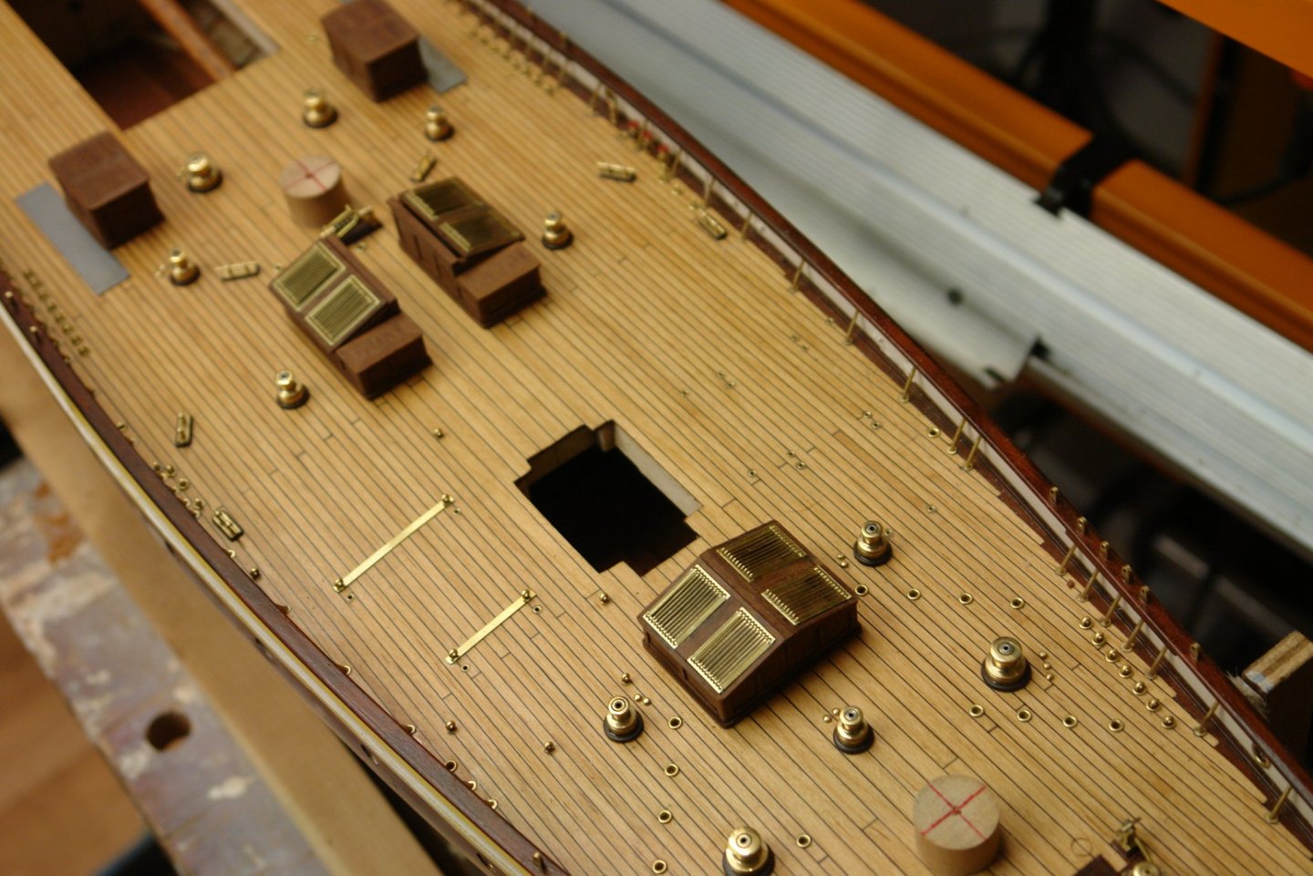


-
Nice little engine Richard, all looking very ship shape.
-
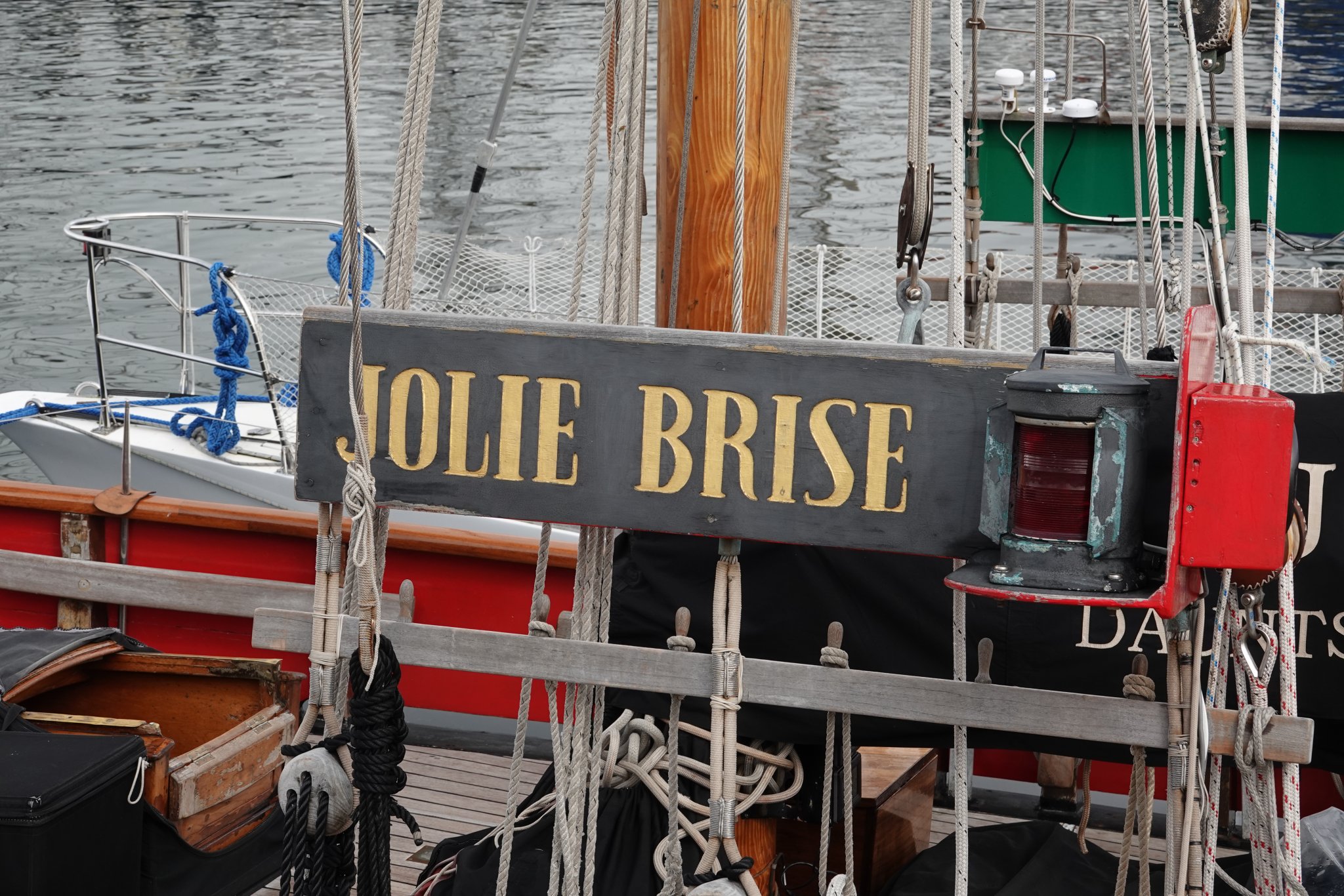
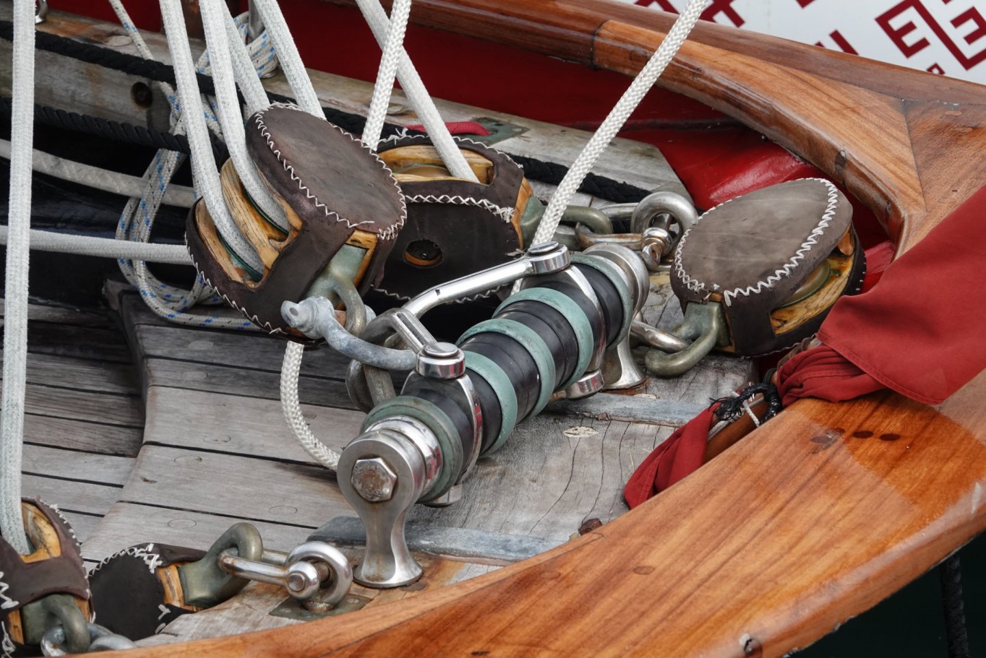
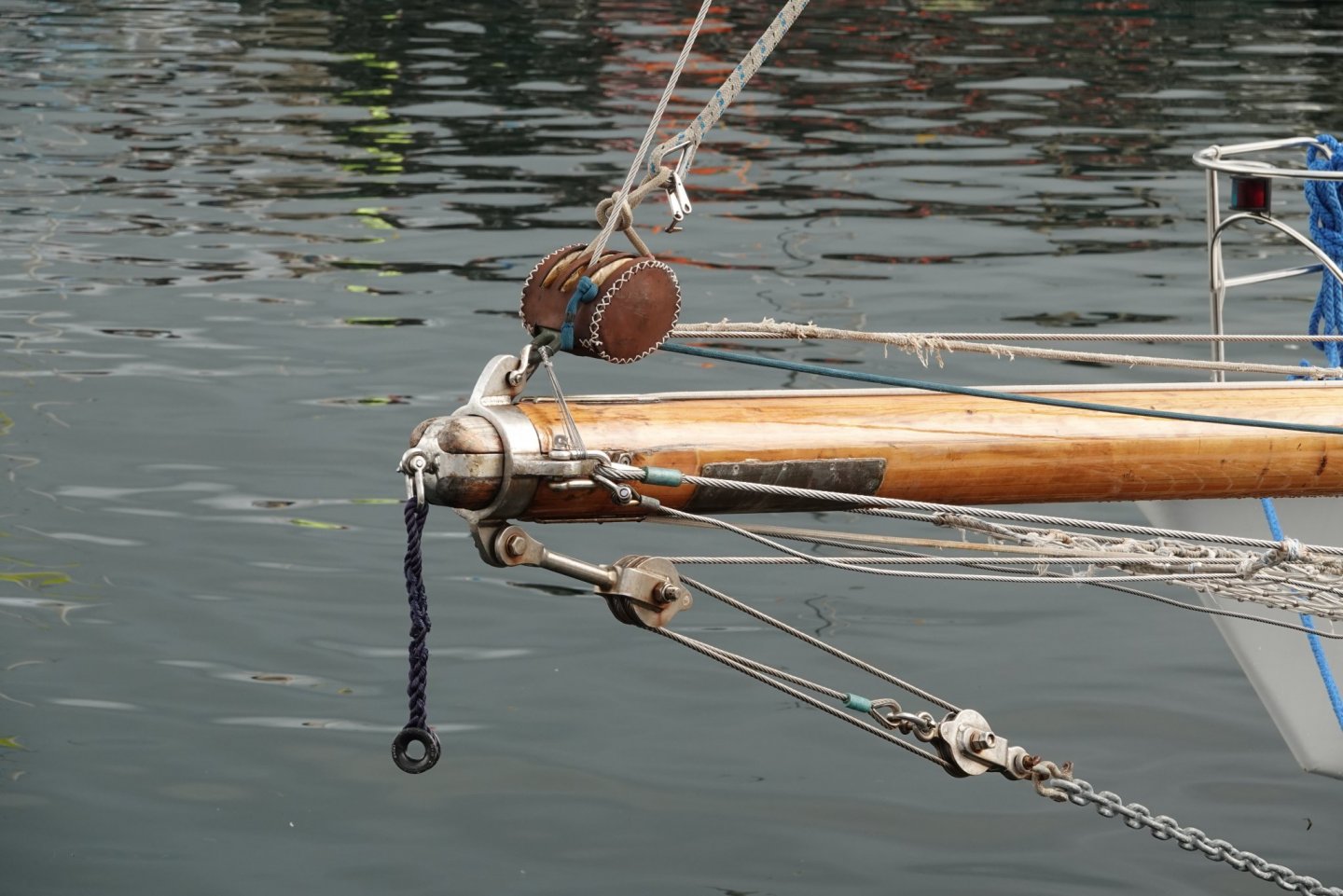
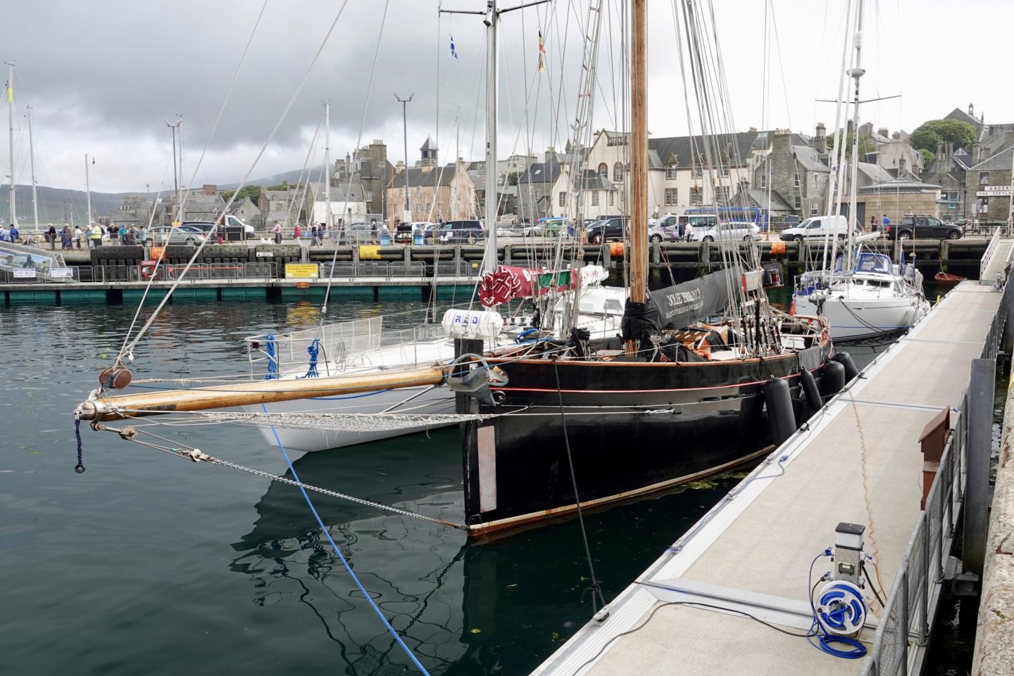
You work very nearly and quickly - the build is coming along well. I was looking at Jolie Brise in Lerwick harbour in August 2019, I took a few photos.

- 15 replies
-
- 5
-

-
- jolie brise
- pilot
- (and 1 more)
-
The hull shape looks quite elegant Jon. I look forward to following the build.
- 23 replies
-
- 1
-
-
- dancing feather
- pilot schooner
- (and 1 more)
-
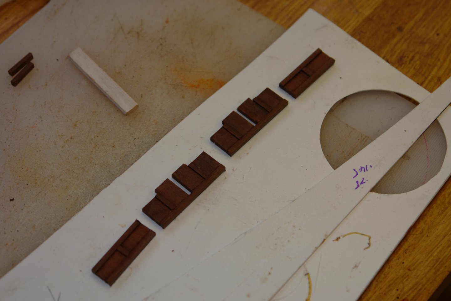
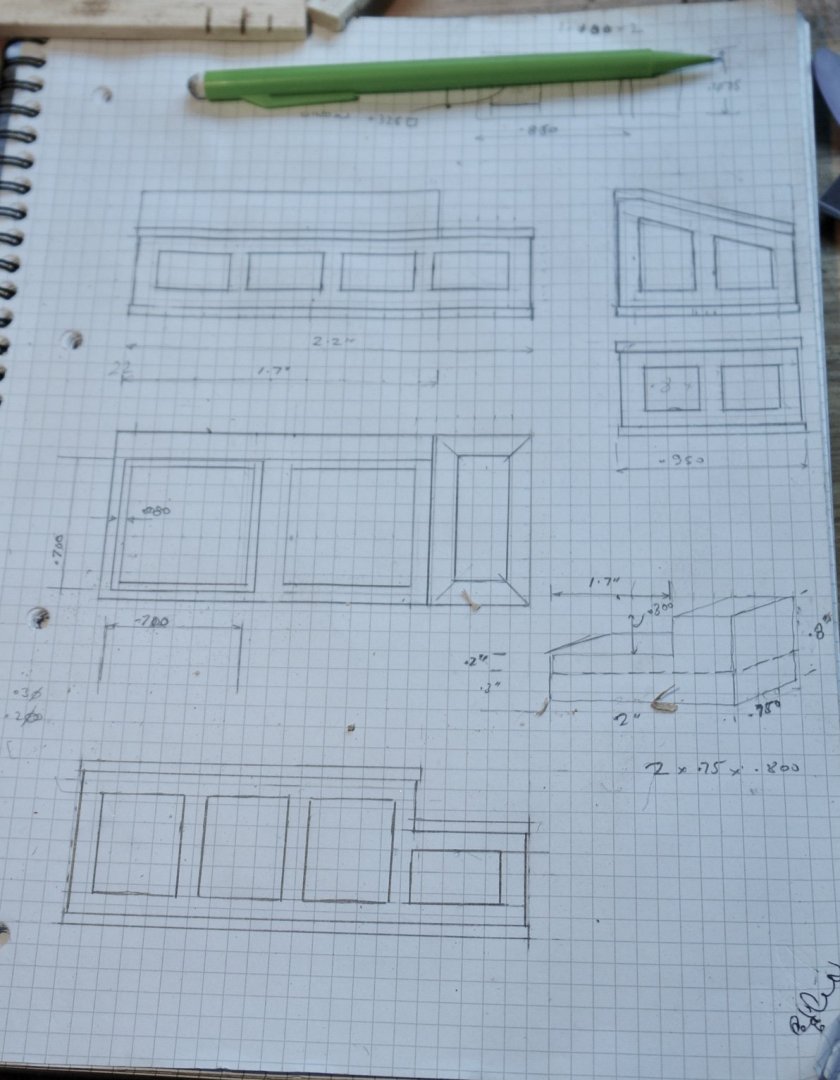
Thank you Richard. Yes Patrick - the same here. Thank god for video conferencing. I am slowly working my way through the deck houses - so this is sort of a repeat of previous posts. That being the case I'll post the photos with a minimum of text. As previously I started with a sketch scaled from the plan and augmented with measurements taken from photos. Each square on the sketch represents 0.1". I made more window frame edge strip. I made more brass edge strip. Another 88 0.6mm diameter holes all drilled with the same carbide drill used for the previous 96 holes - now a total of 184 holes. Is this a record? The edge strips were installed as per previous post.

-
Thank you Hubert and Sceatha. Roger - a possibility - but all the other deck attachment points are of the conventional eyebolt type. Thank you for the complements Pat. I sometimes wonder how you manage at miniature scale so I too find your work impressive. As for staying safe its difficult not to be when confined to barracks. I think this is going to be going on for a long time. Thank you Gary, modesty compels me to point out that the mill did all the hard work. Zbip - yes others have suggested this use - although I am not altogether convinced. A short life line attached somewhere near the centre line is a better way of keeping the helmsman on board. Noel - good Idea but it would spoil all the guessing fun. I might try it though.
-
Nicely done Richard - tricky little things to make aren’t they.
-
Sceatha - an interesting subject for modelling - i look forward to seeing how it develops.
- 81 replies
-
- 3
-
-
- egyptian
- byblos ship
- (and 1 more)
-
Magnificent work as usual Gary - loved the recourse to calculation for sizing the otter boards.
-
HMCSS Victoria 1855 by BANYAN - 1:72
KeithAug replied to BANYAN's topic in - Build logs for subjects built 1851 - 1900
Pat - I do like ships of this era, the decks are so clean and uncluttered.- 1,021 replies
-
- 3
-
-
- gun dispatch vessel
- victoria
- (and 2 more)
-
Keith - shirt sleeve weather here for most of the week - but as we are on restrictions it might as well snow. I look forward to the next stage of the build.
-
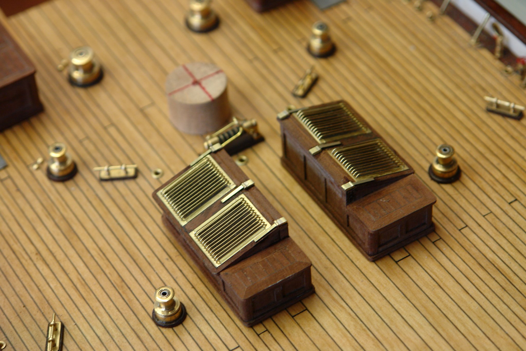
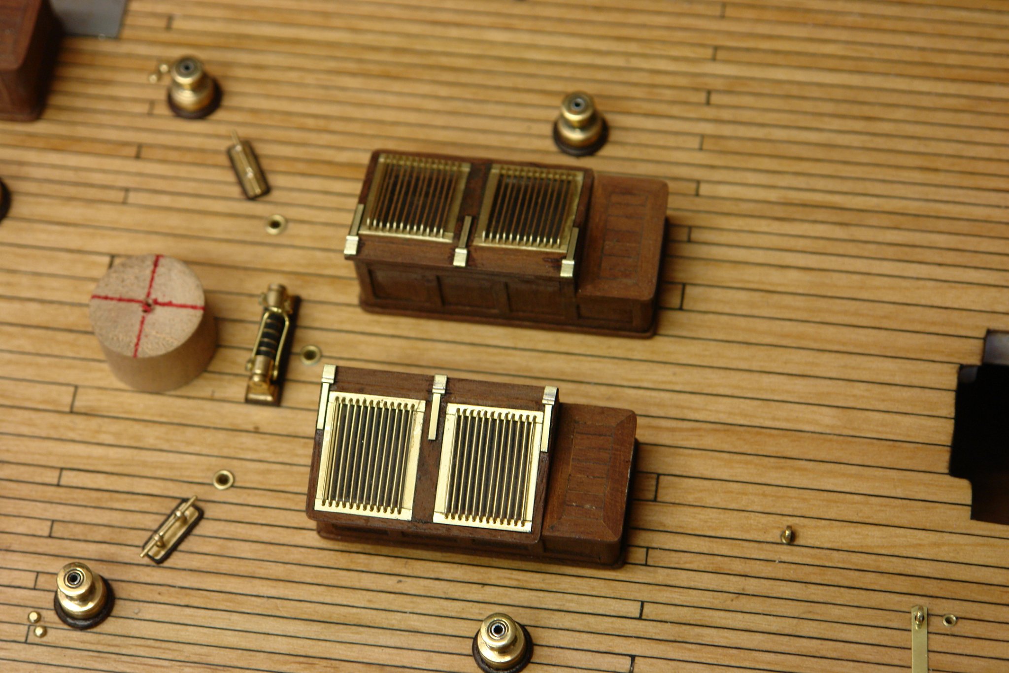
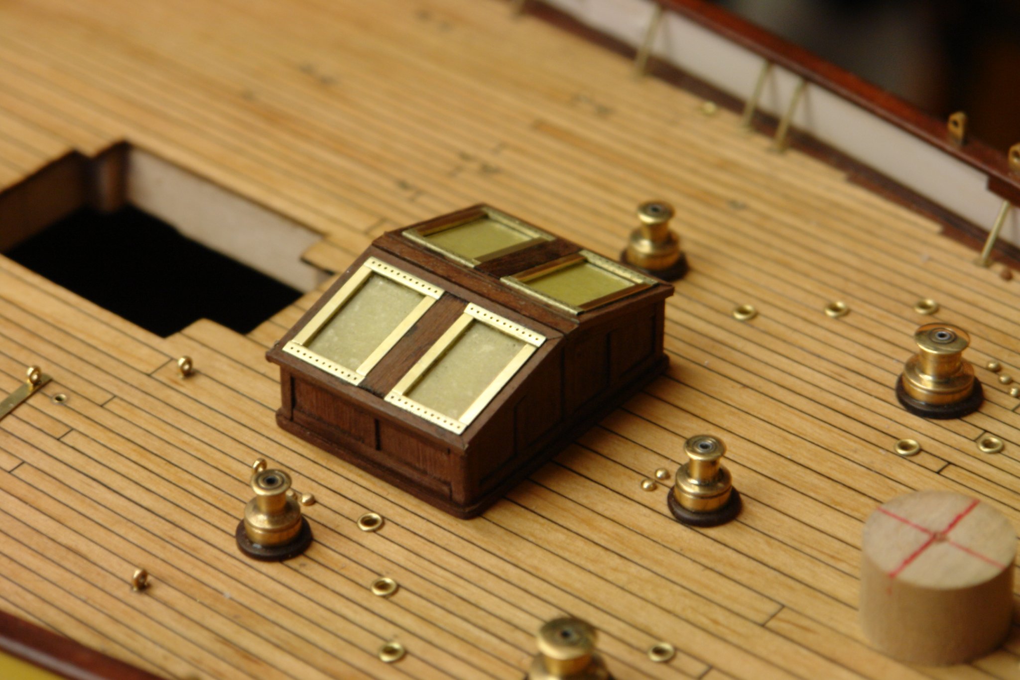
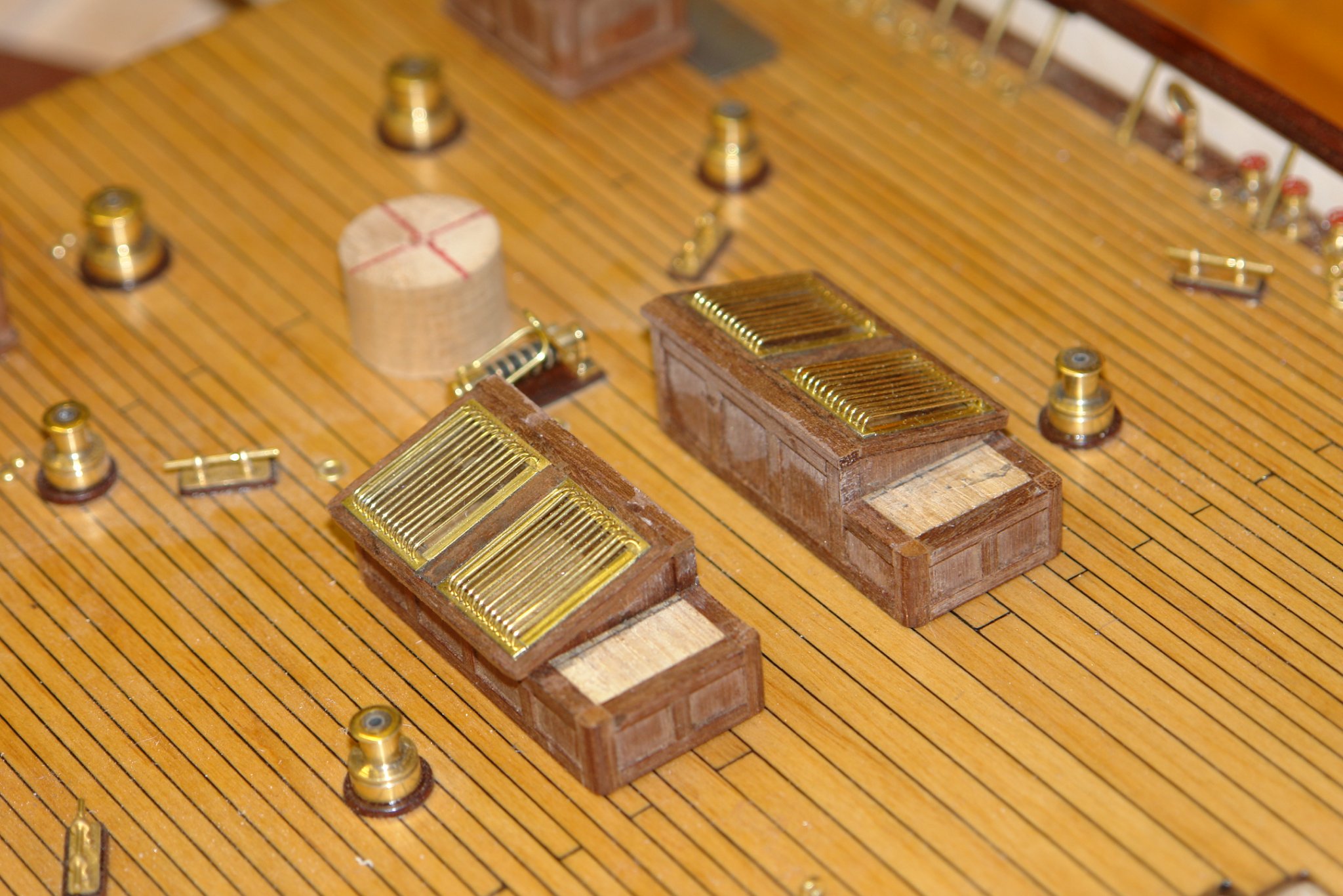
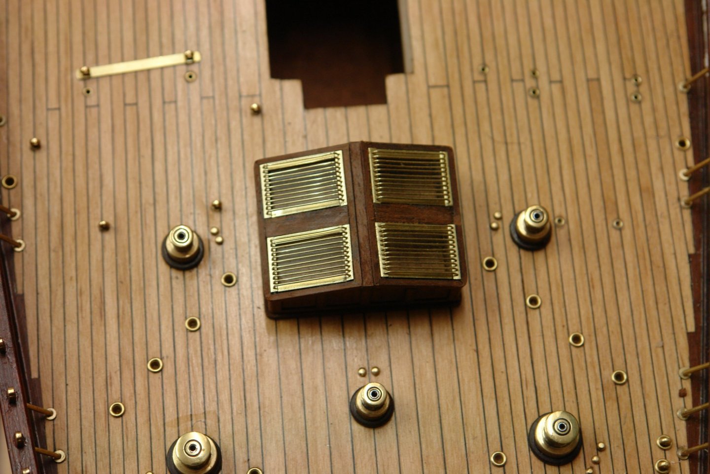
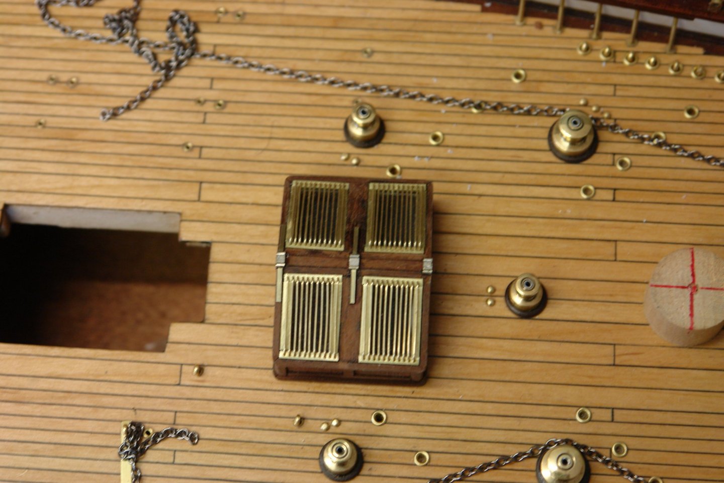
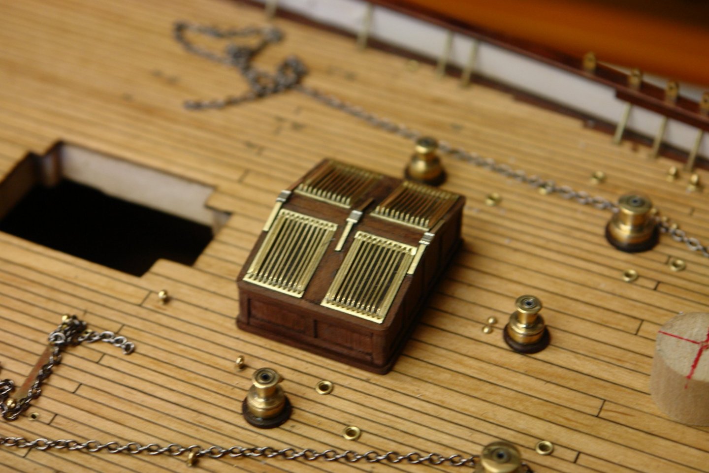
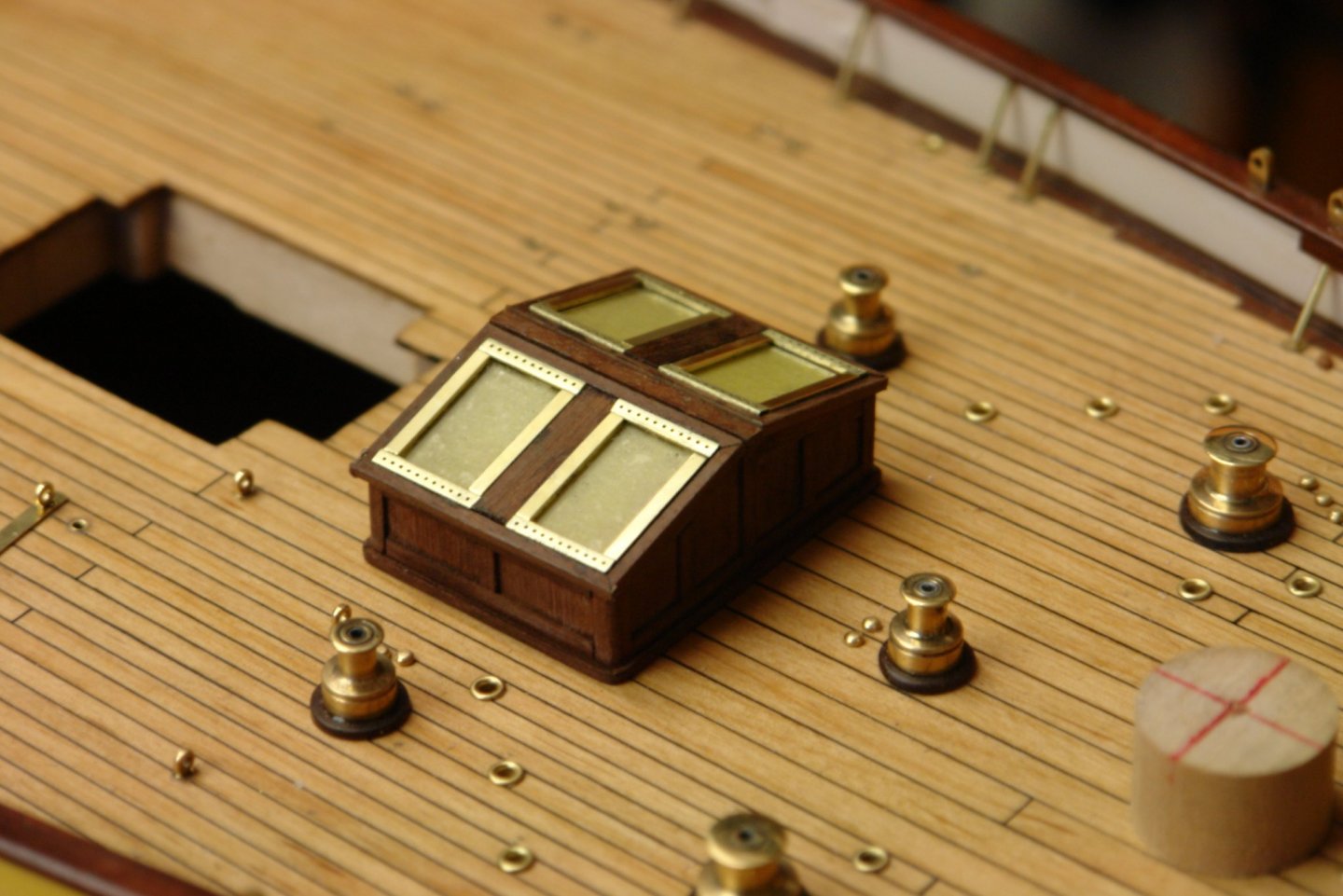
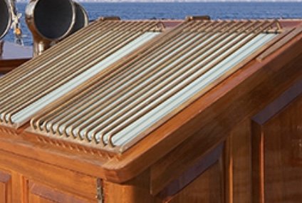
Thank you Eberhard, Pat and Steve - also thanks to everyone for the likes. I finished installing the skylights and completed the small piece of flat surface. Not much explanation necessary but here are a few photos:- I did slight adjustment to some of the bars with the point of a scribe until all the spacing looked even. I still need to add the hinges and vents and of course will need to paint them with poly.


-
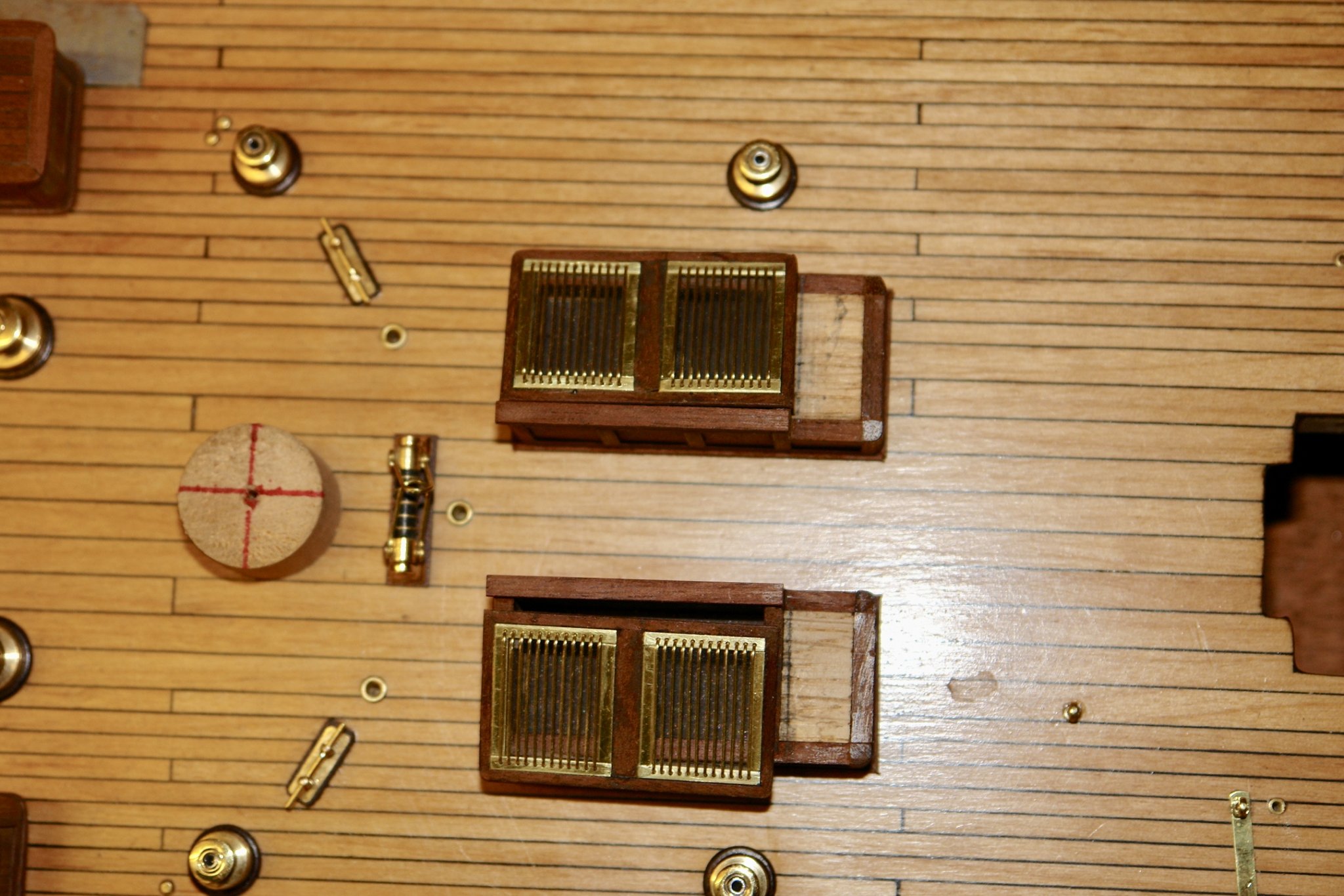
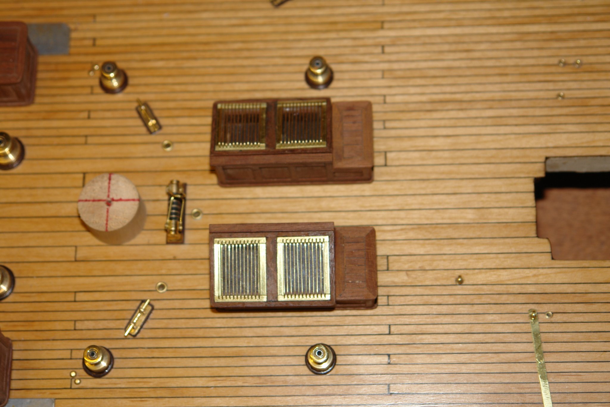
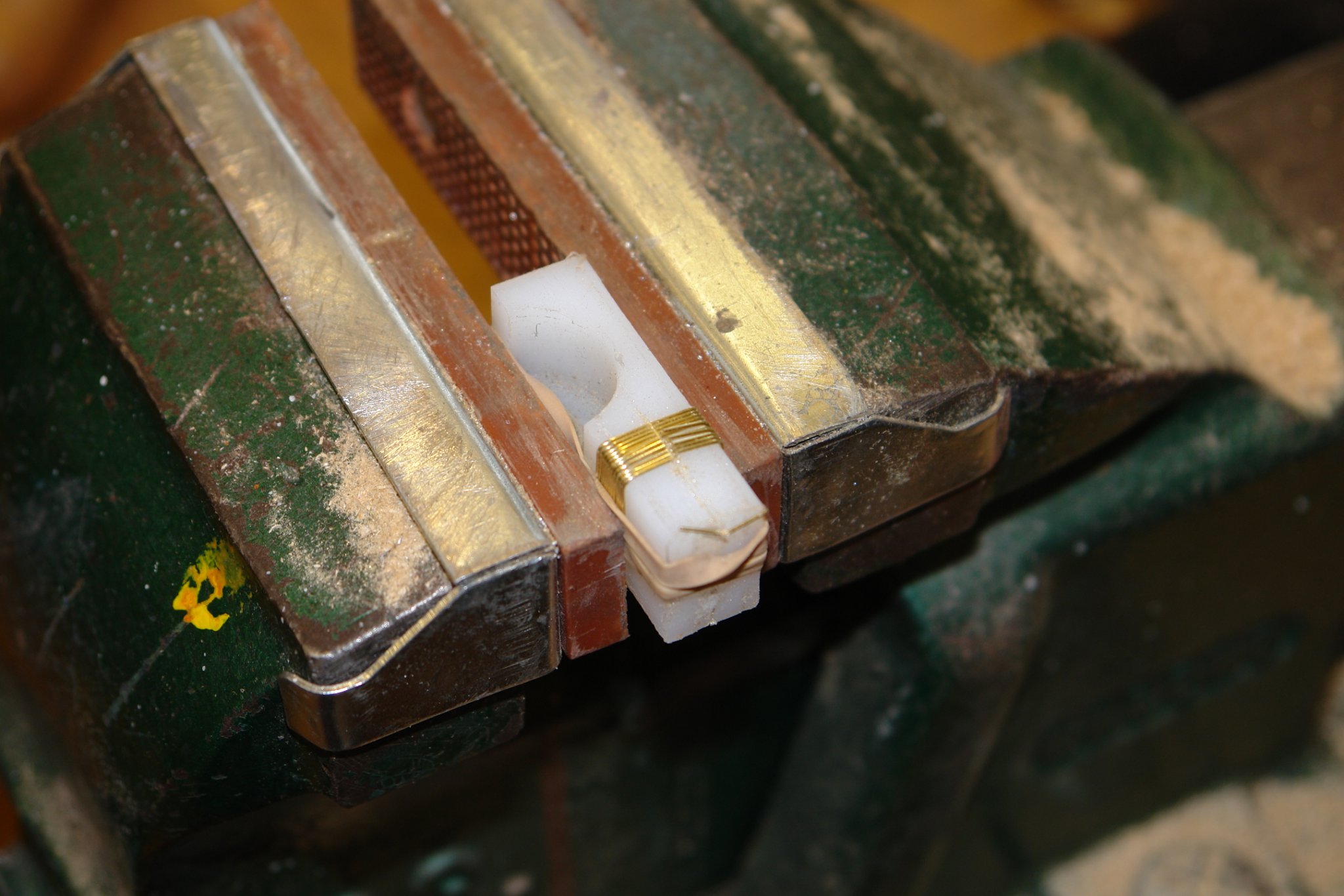
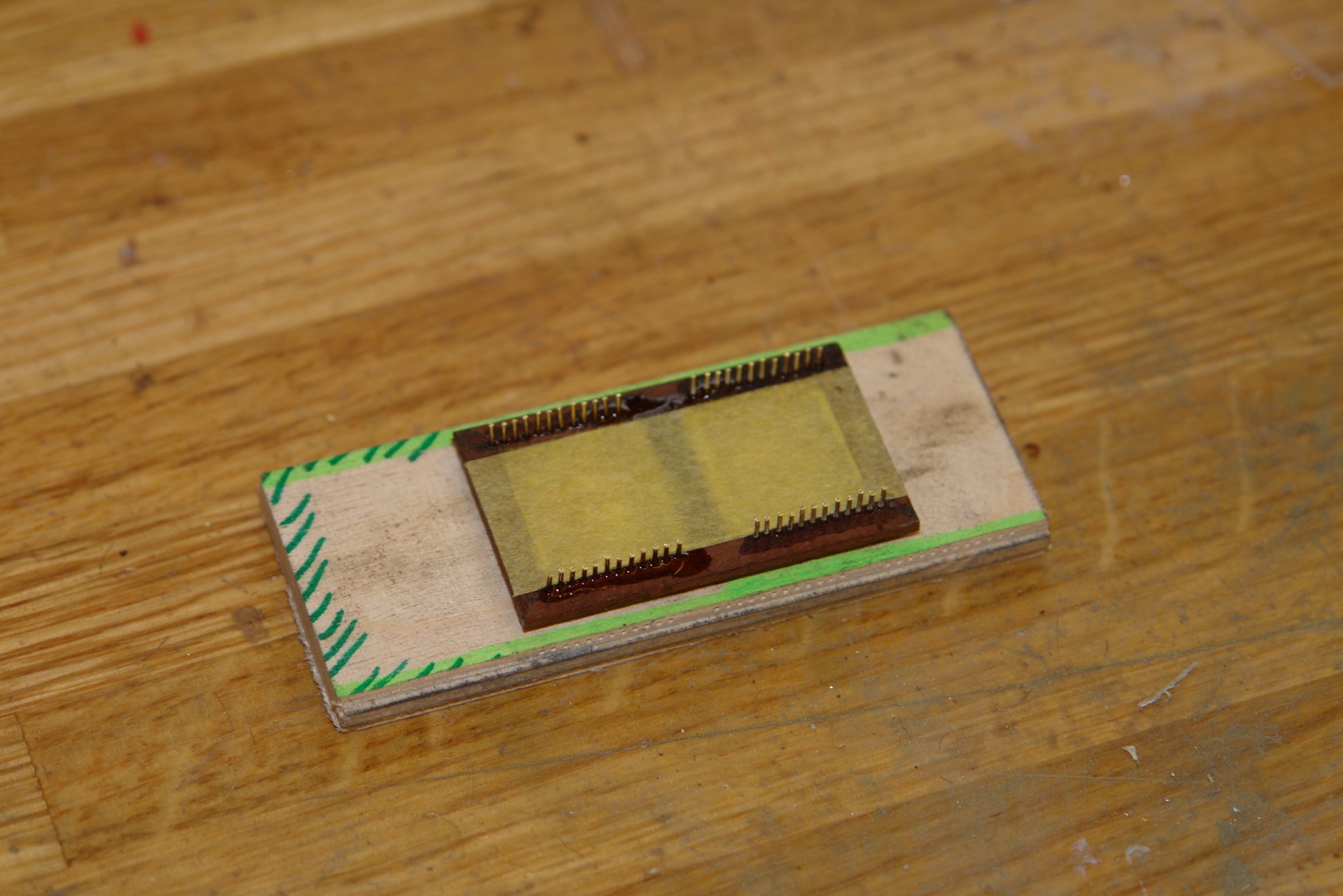
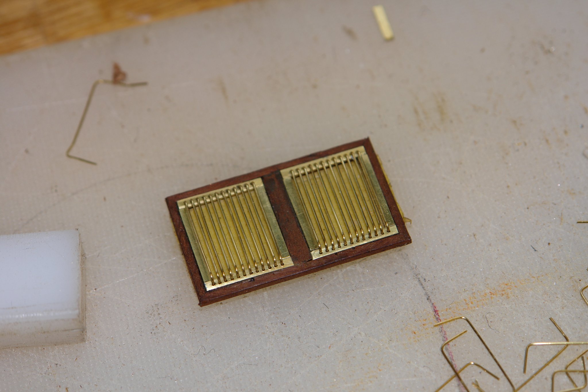
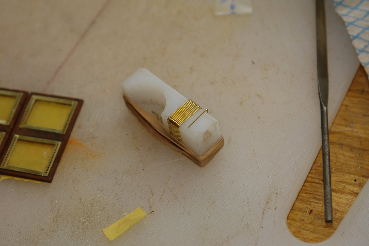
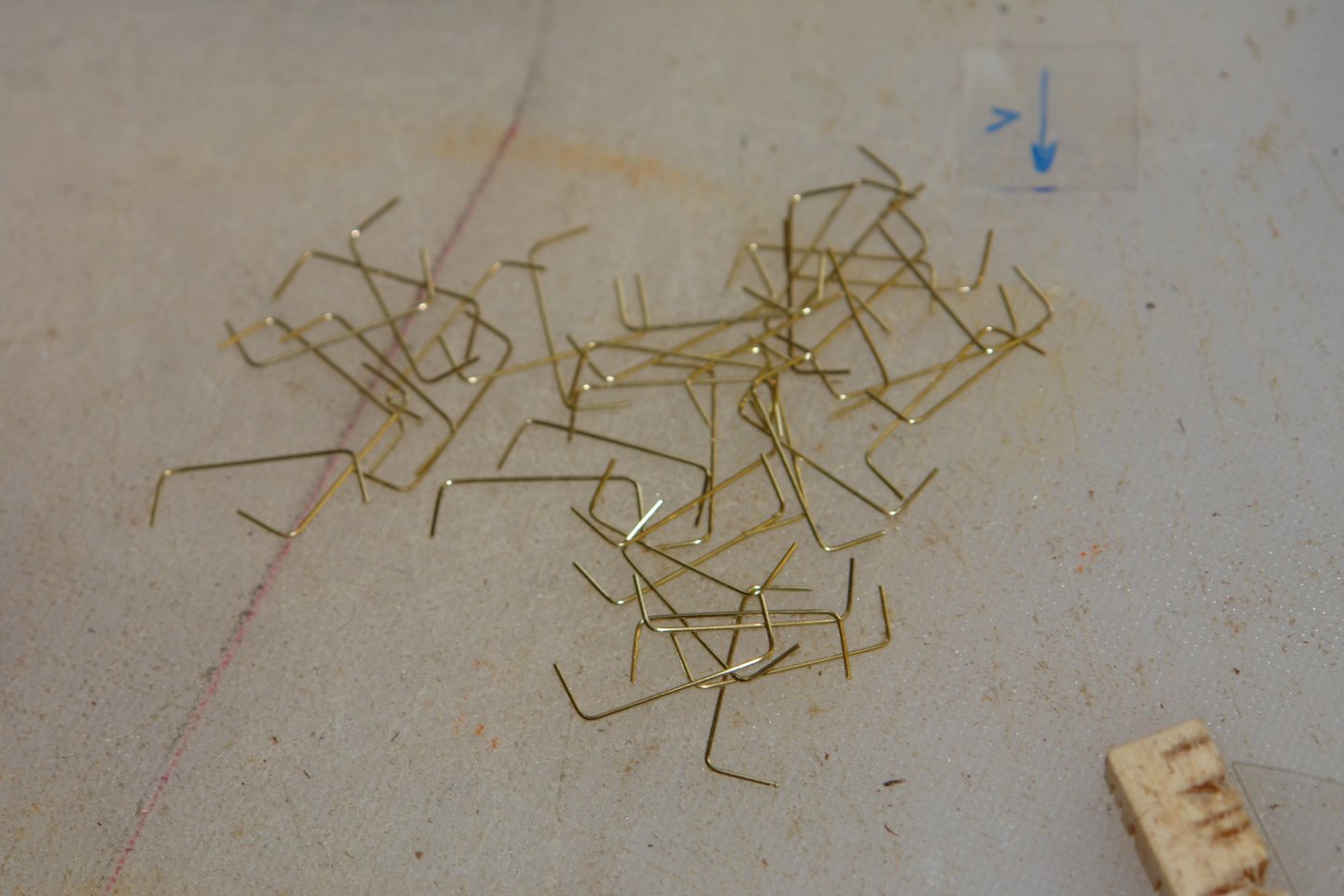
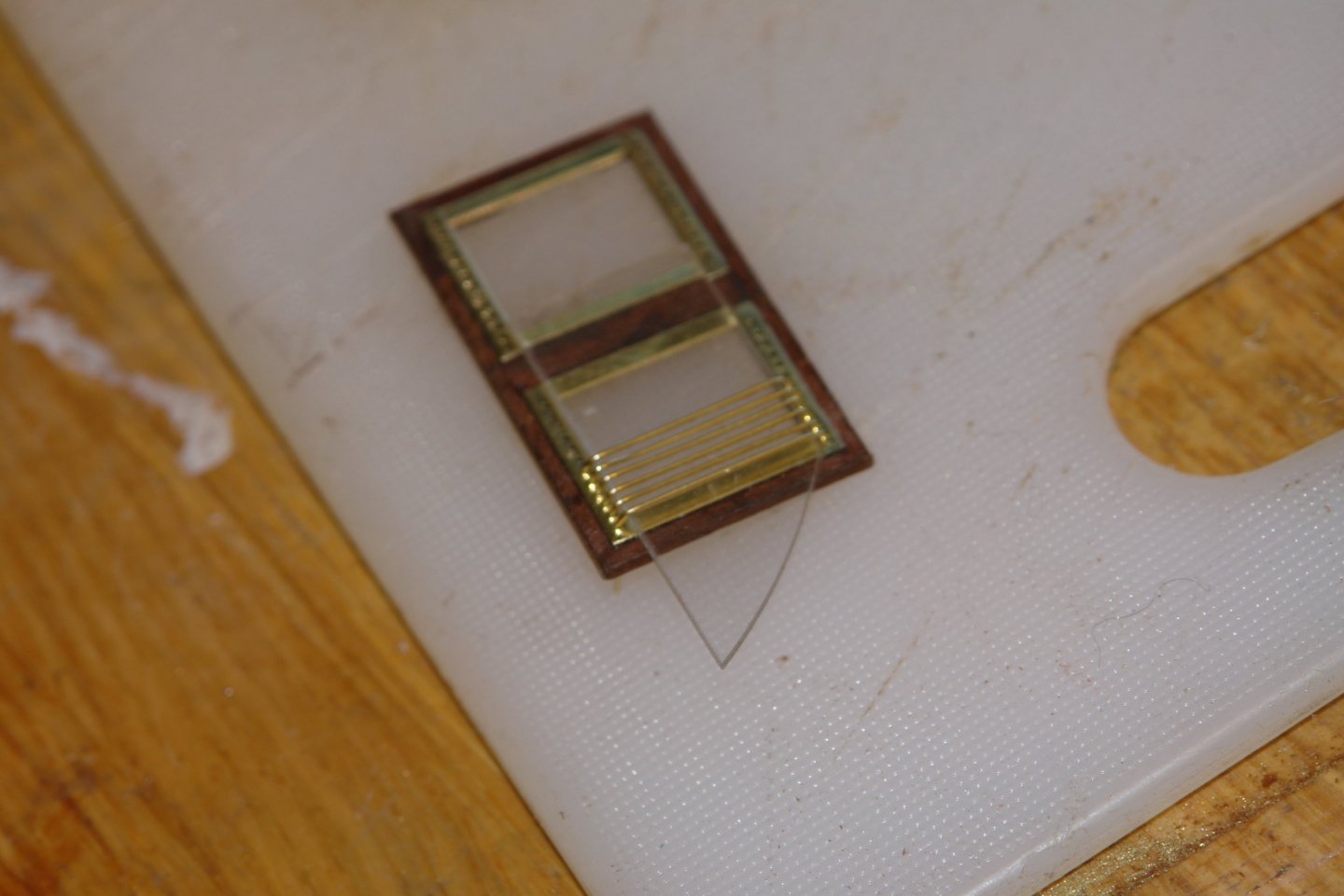
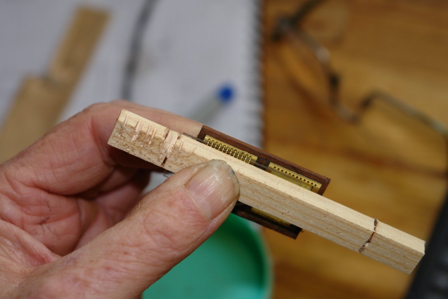
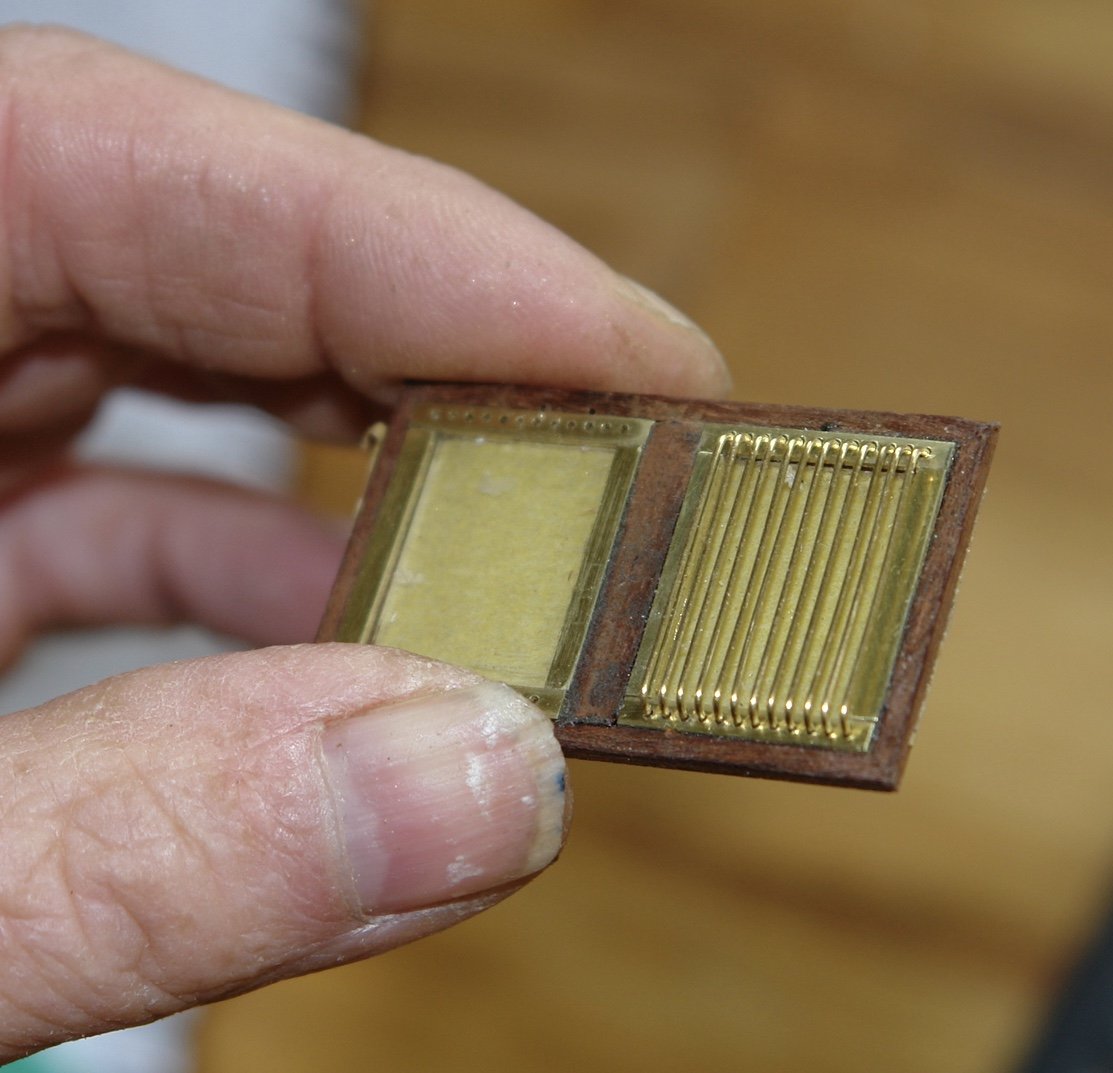
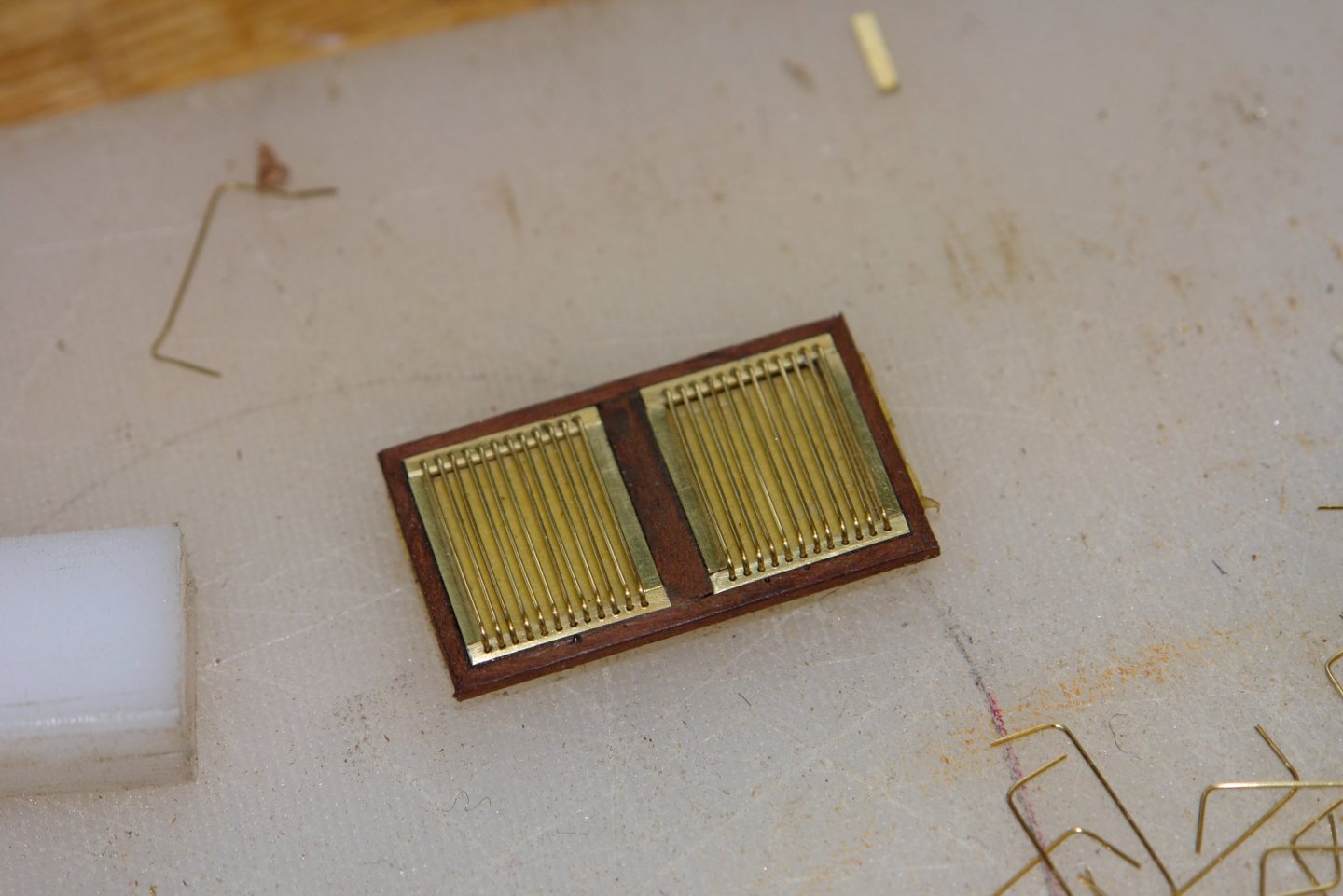
I spent some time working on the skylights - quite fiddly work. I like trying something new but I can be quite slow until I have worked out the technique. You can see from the photo that the bars stand above the glass. Having made the skylight frames I glued the predrilled brass surrounds into the rebates with CA glue. I then drilled the frames through the holes. I then made a former for bending the brass bars out of a scrap of nylon. This was milled to the required size. The bars were made out of .020" diameter hard brass wire . This was wound round the former while keeping plenty of tension on it. Once wound the wire was held in place by an elastic band. The hoops were then cut using a piercing saw. The bars turned out identical but had to be re bent to create the 90 angle. The bars were then inserted into the frame. In the next photo the depth to which the bars are inserted is being controlled by a piece of perspex temporarily placed above the frame. The end of the perspex can be seen as the triangular shape on the lower edge of the frame. With all the bars for the first window inserted the bars were pressed hard against the perspex and then glued with CA from the reverse side. I dont have very large hands but you can see the lights are about as big as my thumb nail. The yellow of the windows is because they are being protected by masking tape. The rear view shows the glued projections of the bars - these were cut off and filed flat. Once finished the windows are no longer very obvious. I will slightly rebend the bars to even up slight difference in spacing before mounting.

-
Than you Druxey - I have about 100 more to do on other skylights so I have set myself a challenge. Pat, Unfortunately I couldn't afford the running costs - which I suspect is why Germania has been on sale twice in the last 3 years. It is used for charters and I suspect Covid 19 has put paid to that for a while. I suspect it will sell quite cheaply.
-
My memory failed me - she is currently on sale for a mere 5 million euros, just popping out to see if the bank will give me a loan!!!!!
-
Pat - I would have done the same had I not been impatient. Not sure the photo etch industry is open at the moment in the UK. Richard - Yes - the woodwork was well done. I don't think I could afford a weeks hire let alone the cost of building. I think it resold recently for about 15 million euros.
-
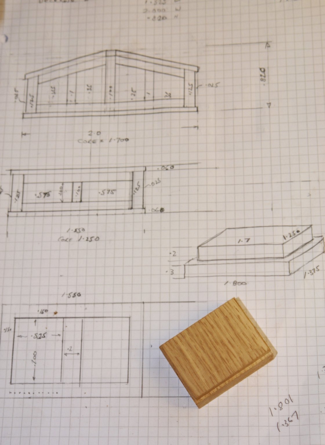
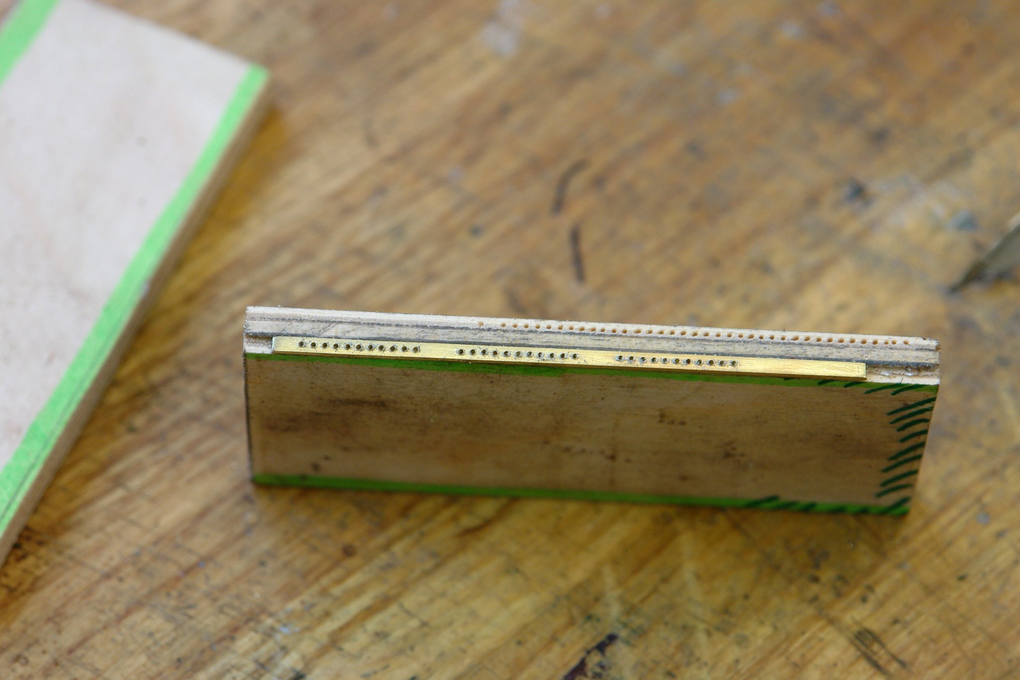
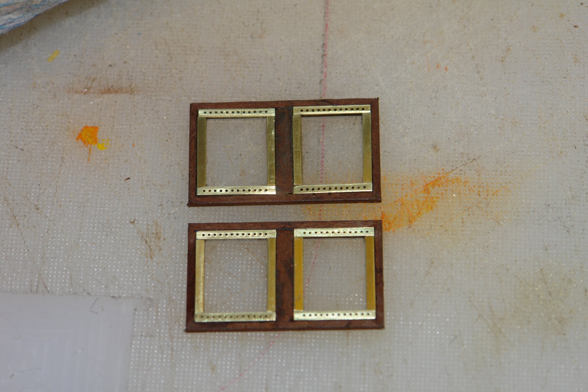
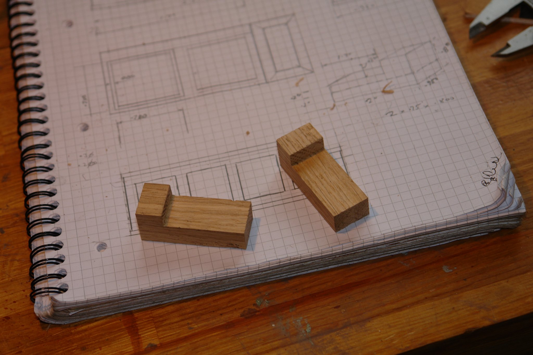
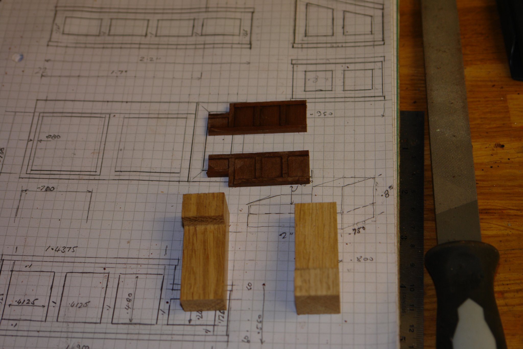
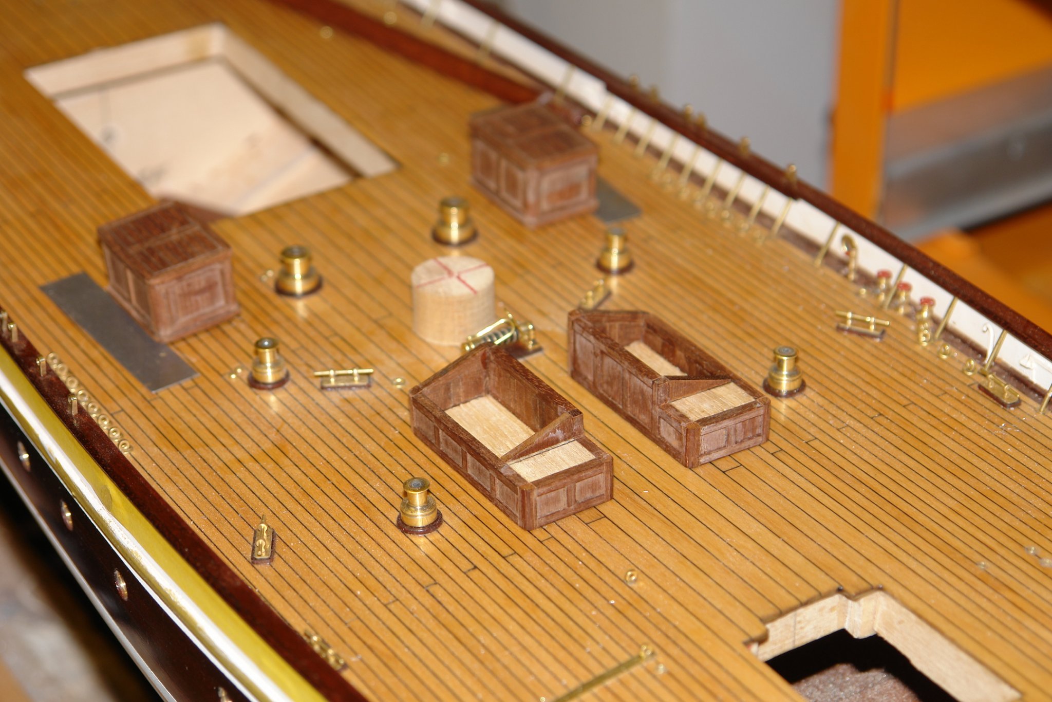
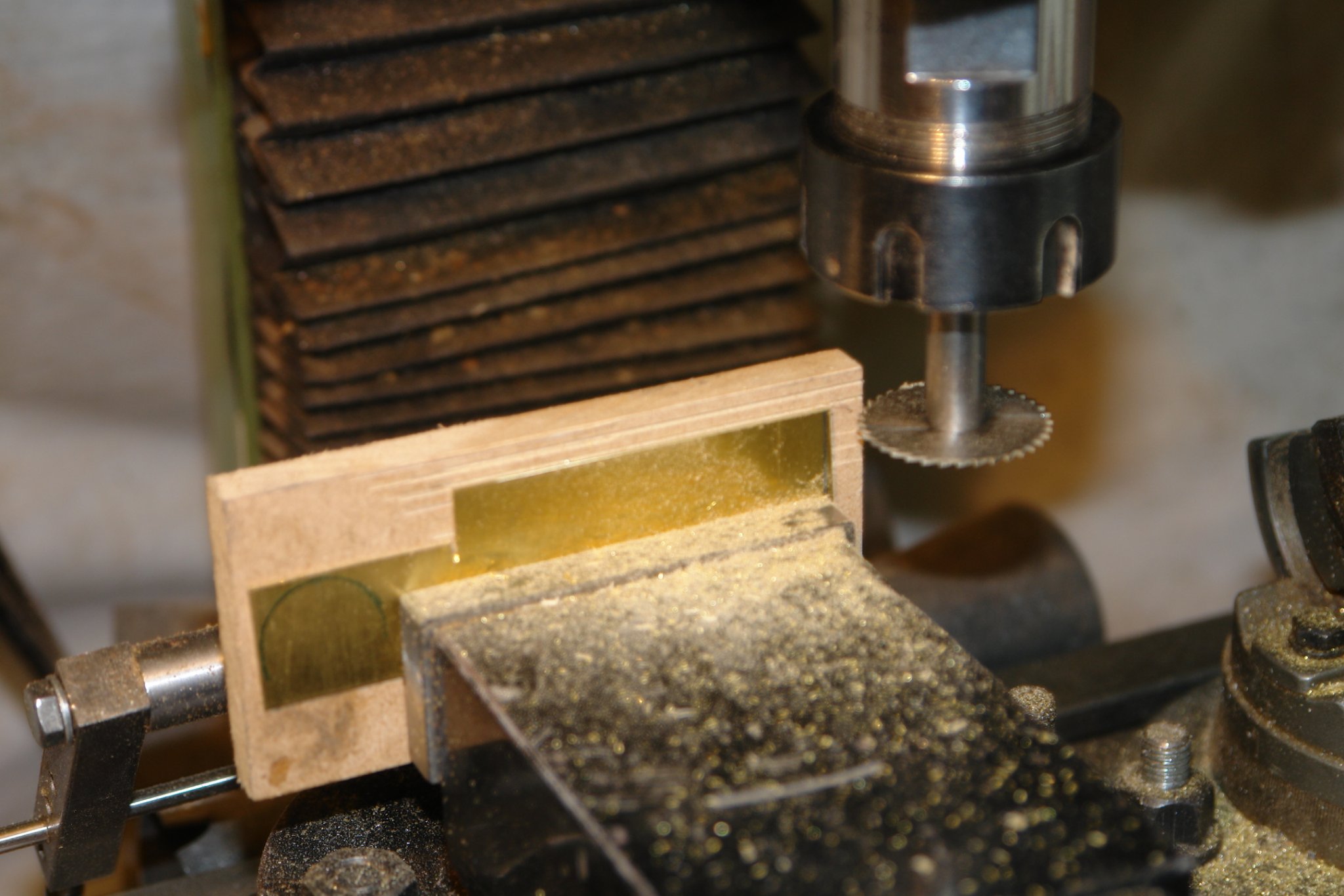
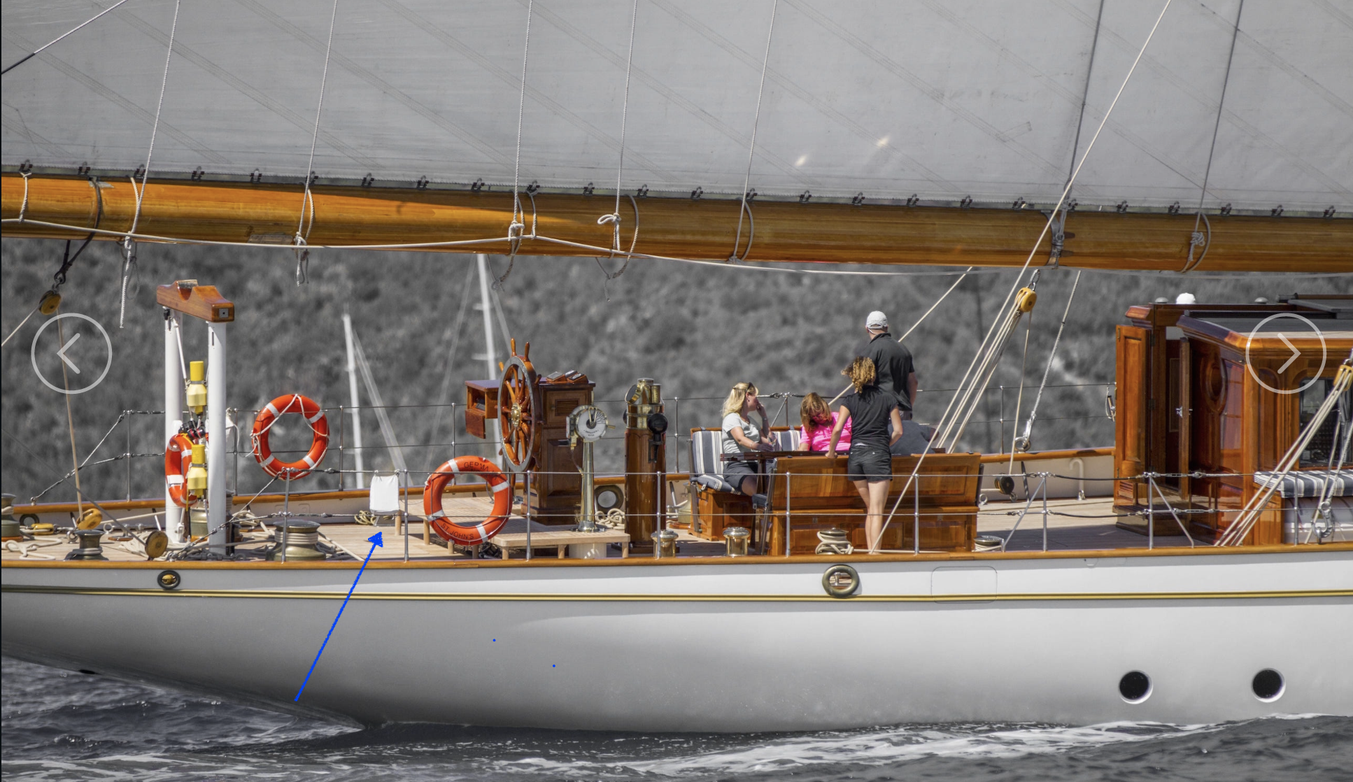
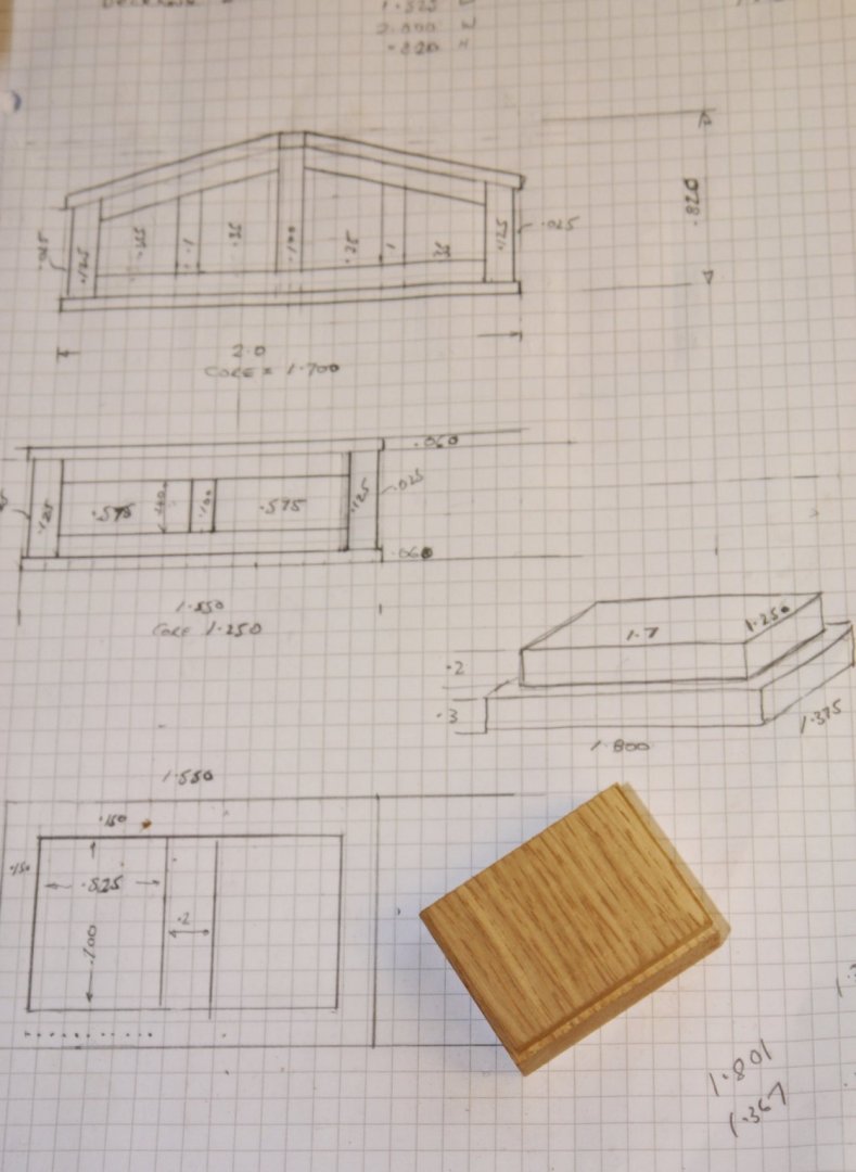
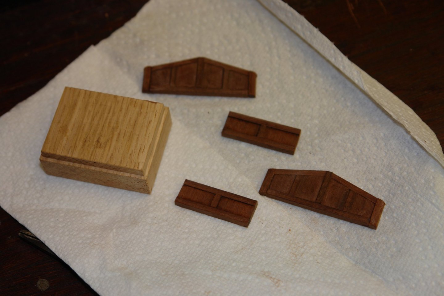
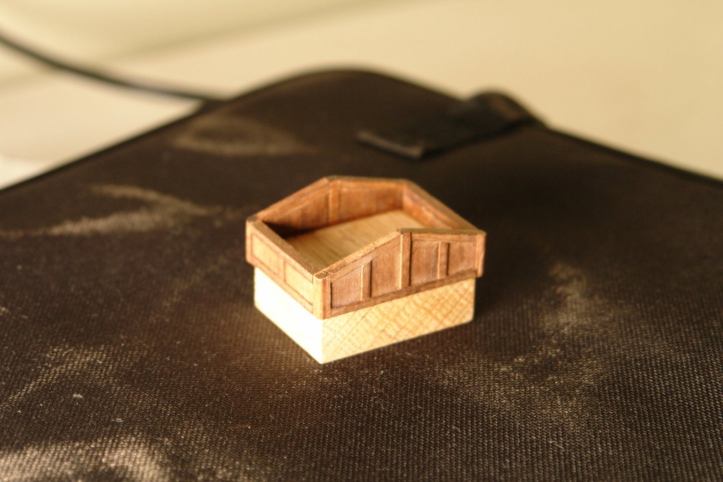
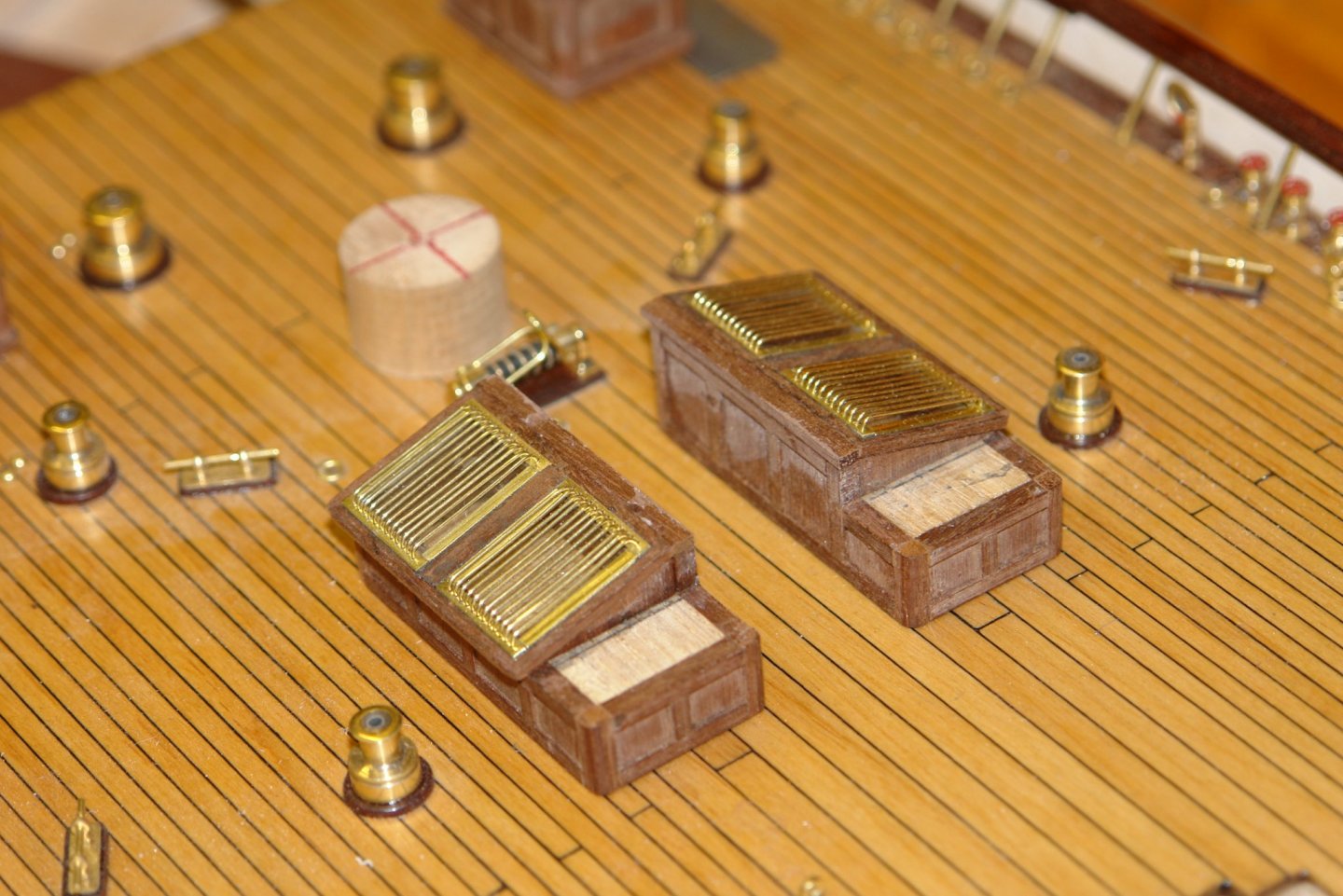
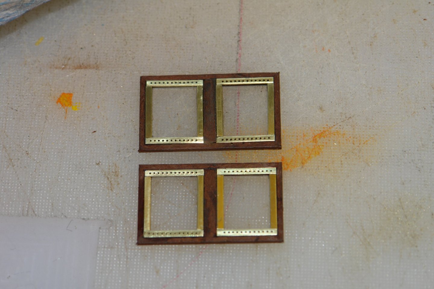
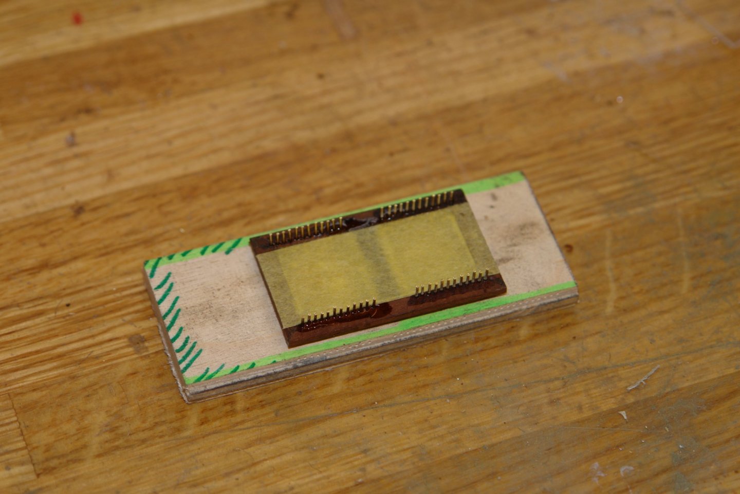
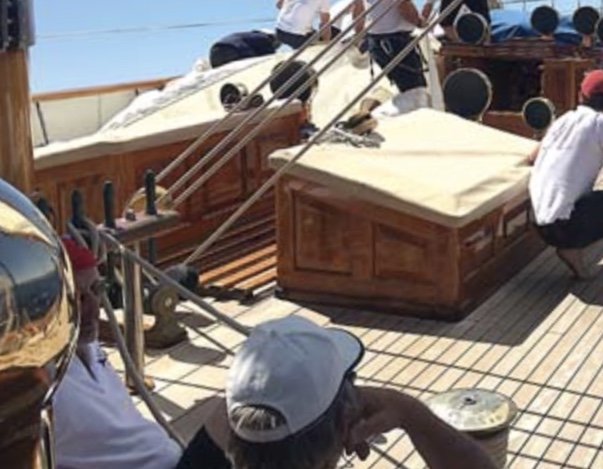
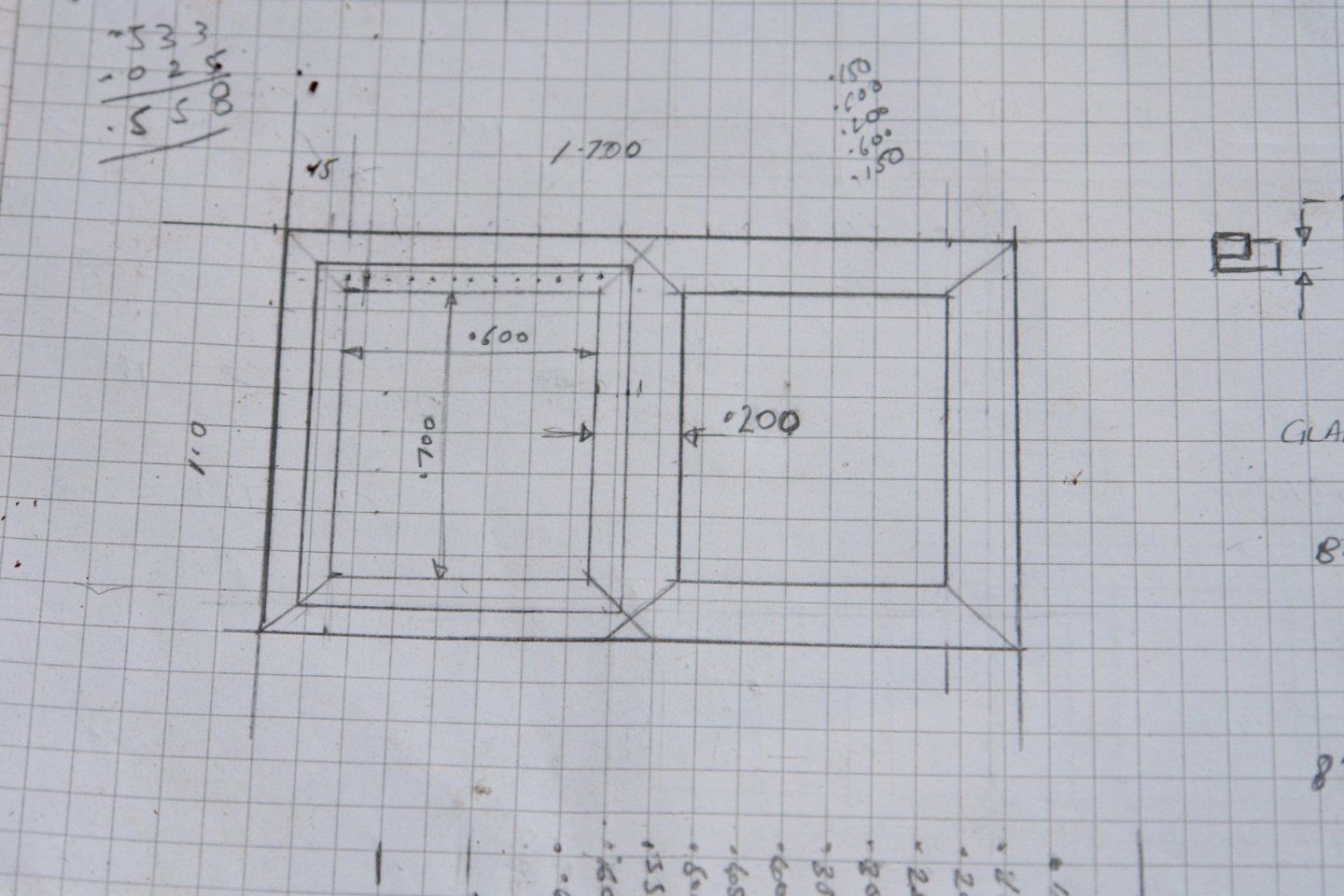
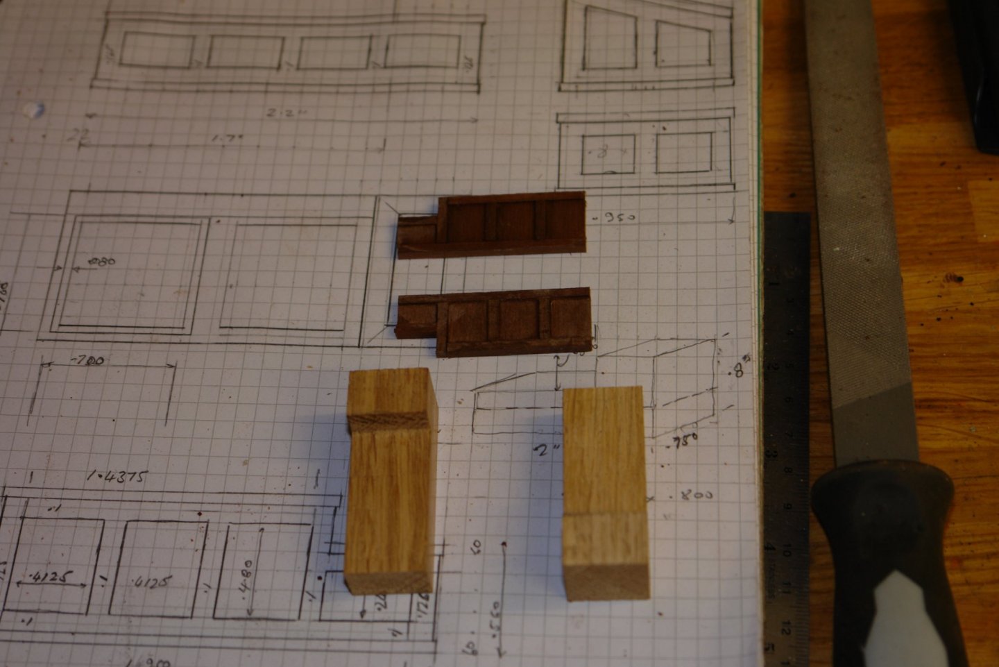
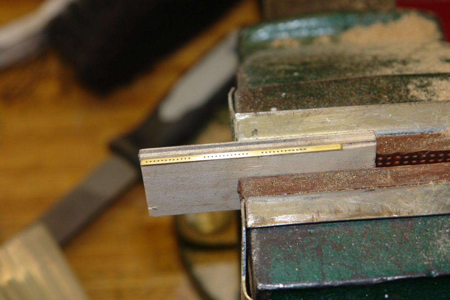
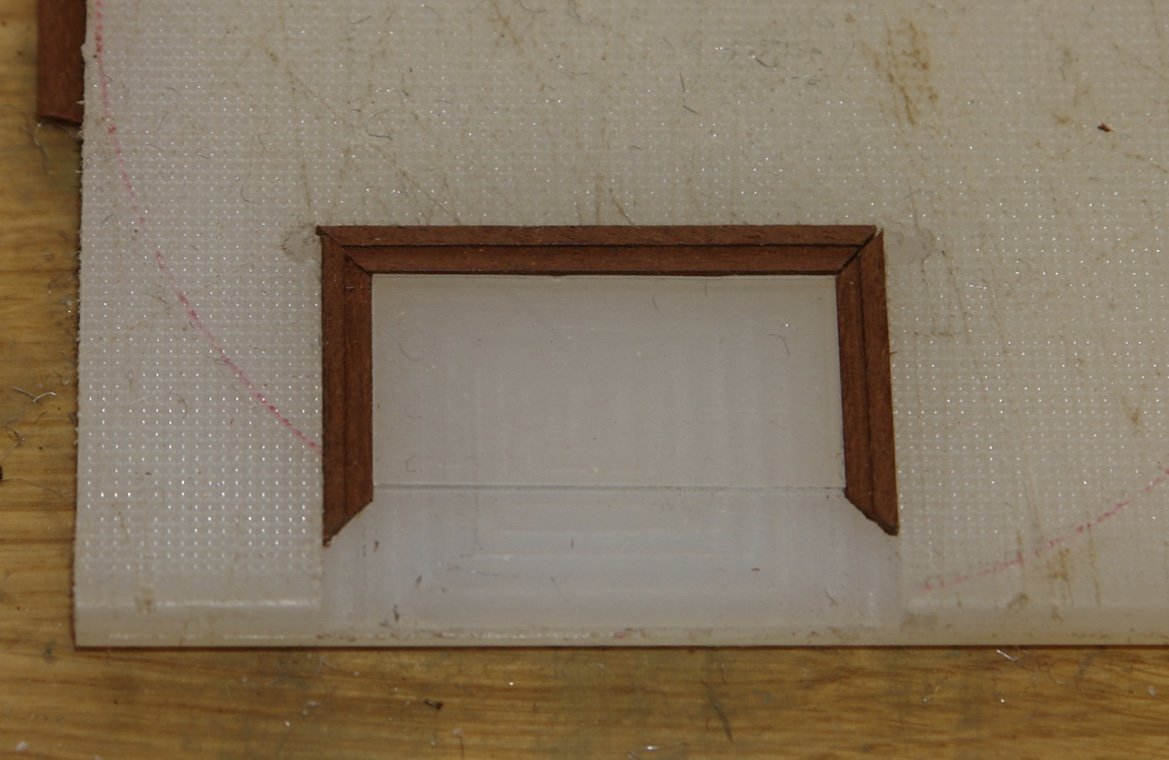
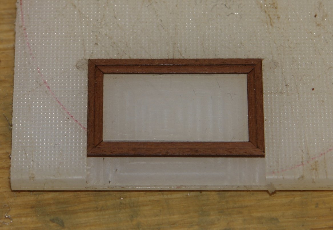
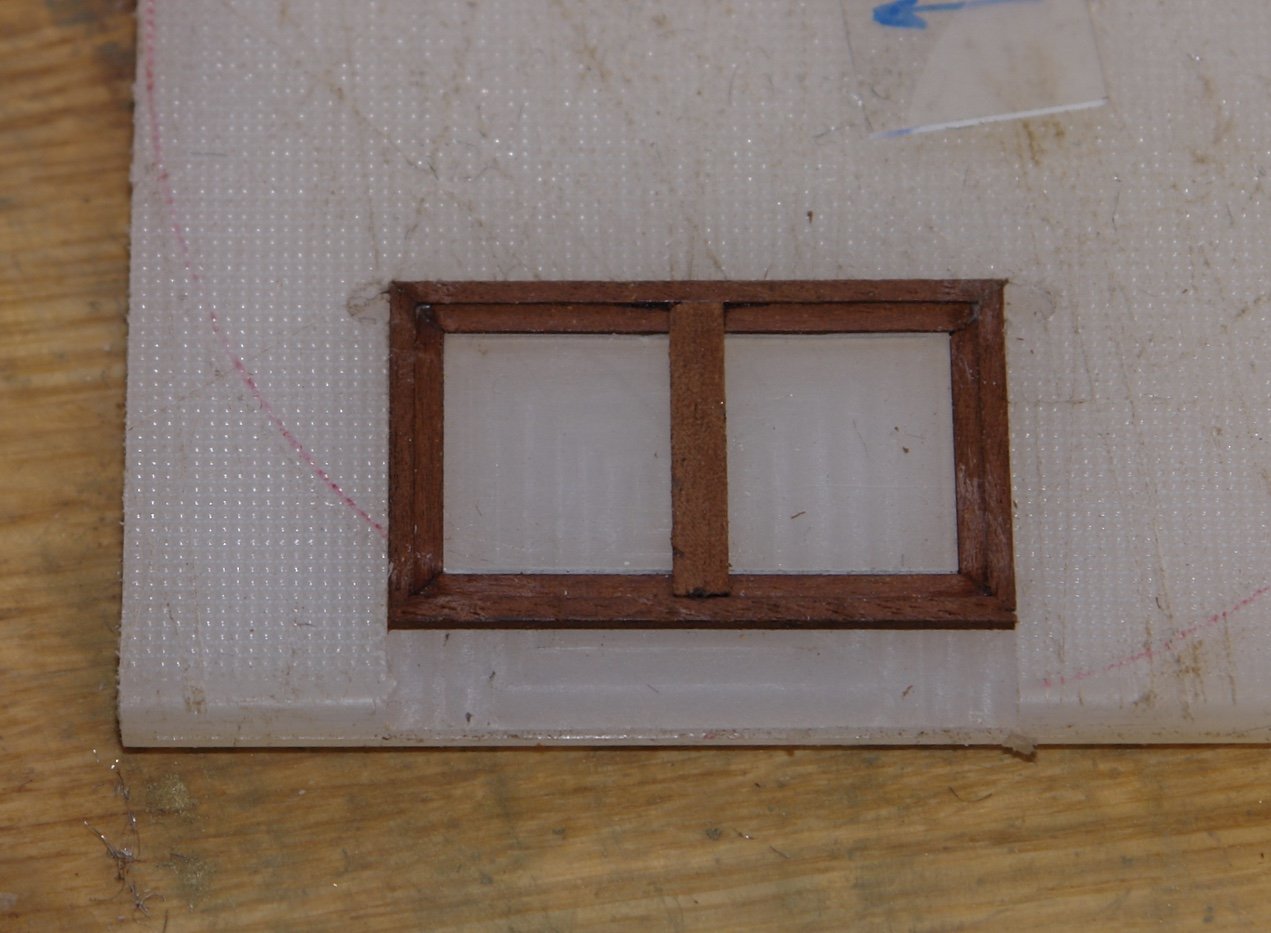
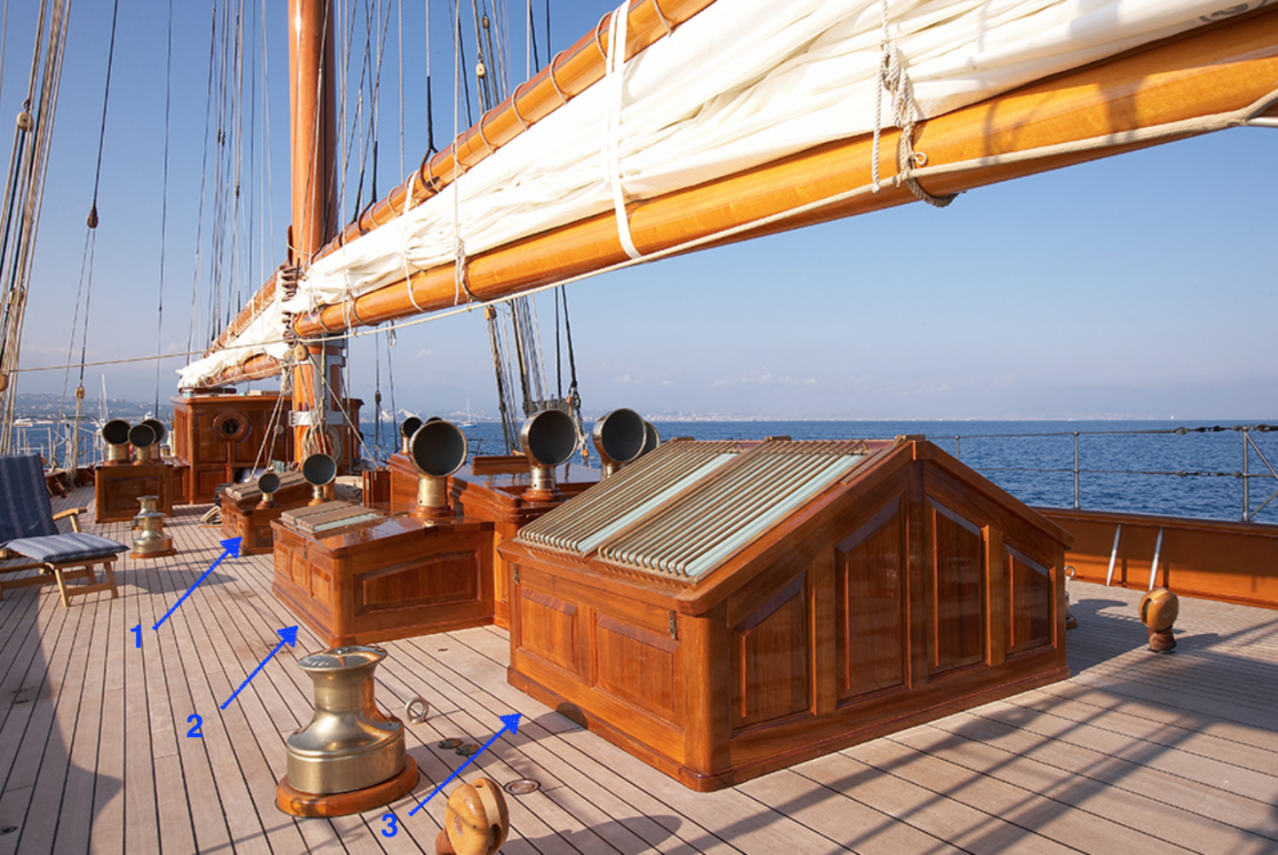
Pat - Mark is correct - they don't align with any obvious deck hatches for machinery. The rear pair of deck features house both skylights and vents. I don't have a good overall picture but across several photos I do have the necessary detail. The following photograph is the best overall shot. I sketched them out at twice size - each square represents 0.1". Overall dimensions are 2.2" long, .950" wide and 0.8" high. I also sketched out the skylight frame. The core was once again made from oak but this time it was cut back so that the skylight were above a void rather than solid wood. The blocks were clad as done on the previous deck features. The skylight frames have a brass surround and it is on to this that the protective bars are mounted. I cut .075 wide strips from .031" brass sheet to make these surrounds. I then drilled holes along the centre line with a .025" drill to take the protection bars. The hole spacing is .05" - 96 holes in total, without breaking the drill - must be a record!!!!!! To make the frames accurately I took an old nylon kitchen cutting board and machined out a profile the same size as the frame. The frames timbers were cut .150" x .060" with a rebate .075" x .030". The windows themselves were made from .030" perspex sheet. In the next photo 3 sides of the frame are position in the cut out and the window is in place. Nothing is glued as this is a trial fit. The next shot is the completed frame with the window in place - glued at the corners with PVA. It is a bit fragile at this stage. I then glued a .2" by .030" strip of wood down the centre to create 2 windows. The next job is to fit the brass strips in the rebate.


-
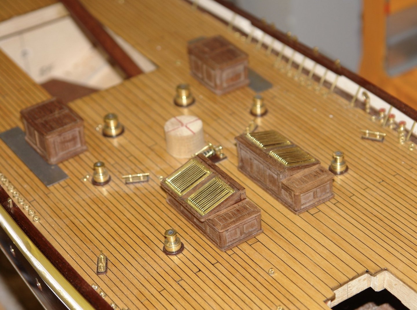
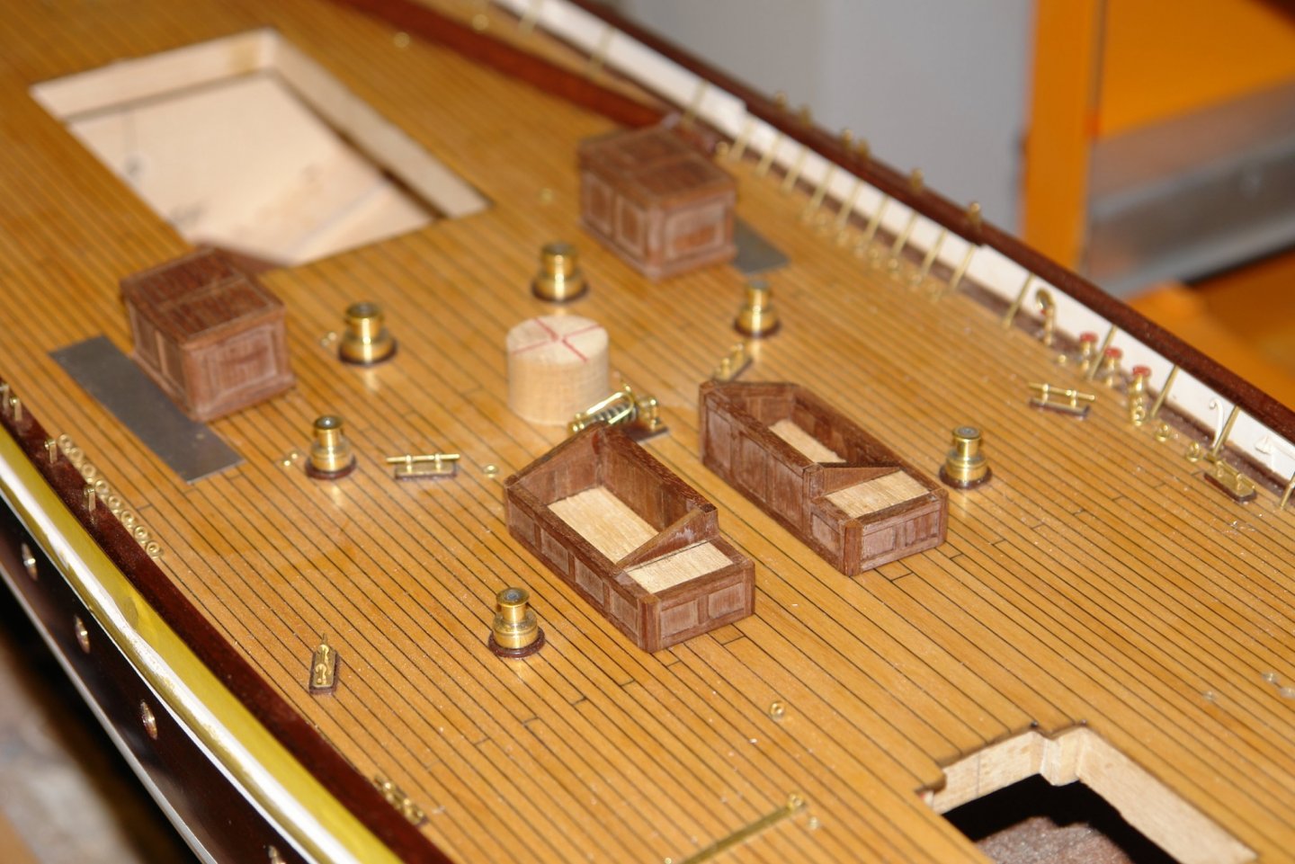
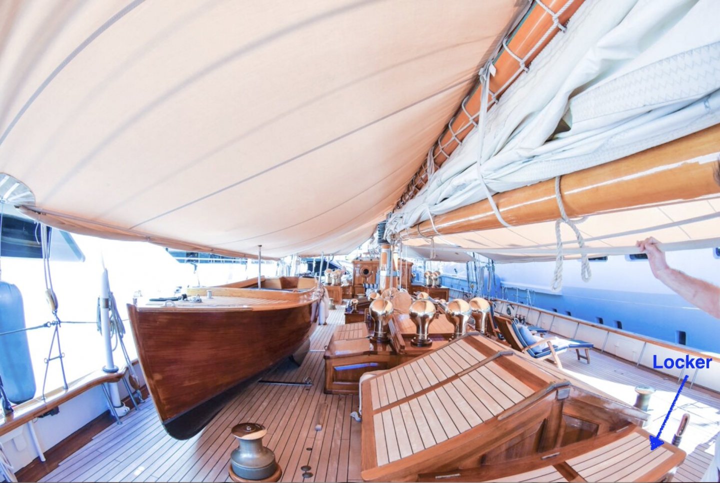
I have decided to concentrate on the deck structures between the main and foremast for the next phase of the build. I need to start by sorting out what they are going to look like - surprisingly I have options. The next photo is an early photo of the Germania. You can tell the early photos by looking at the inside of the bulwark. As constructed this seems to have been painted an unattractive brown. During a later refit many detailed changes seem to have been made as can be seen in the next photo. The most significant difference appears to be that the deckhouse tops have been changed from skylights to wood. I sort of think this may not be a permanent difference and that possibly the 2 versions are interchangeable to suit racing / cruising usage. I think the skylight version is both more interesting and more challenging to build so I intend to go with that. In the later an additional deck locker appears and a number of other detailed changes can be found. I will comment on these as I continue the build. Anyway getting on with the build I will start with the twin deck houses at position 1 - but first dinner is ready.
-
Mark, Pat, Mark. The brackets are only at the stern and I don't think they are substantial enough to lift the boat. They could have something to do with sail handling but the few shots of Germania under sail don't show them being used - see photo (remember you are looking at the bracket and don't get distracted by other deck features). Thank you Richard.

-
Welcome back Patrick. I missed you and on more than a few occasions wondered what you were up to. What a lot of cabins she has and all so nicely fitted out. At least this one looks like a boat.
-
Geert, I liked the work ol the rudder, the sweep of the tiller is particularly attractive. I thought your numbers were finely done, not many would have gone to the trouble. What did you use to glue the glass together.
-
Keith, I am liking the way the detail is building - it is bringing her to life. The chain work looks particularly good.
-
.Smoke stacks looking pretty good to me and I don’t miss the turnbuckles. All looking quite authentic.
- 599 replies
-
- 5
-
-
- sidewheeler
- arabia
- (and 4 more)