


UpstateNY
-
Posts
466 -
Joined
-
Last visited
Content Type
Profiles
Forums
Gallery
Events
Posts posted by UpstateNY
-
-
Welcome to MSW Martin!
The kit looks great and I am sure your log will generate a lot of interest!
I'll certainly be following along!

Cheers,
Nigel.
-
HI Brian,
Love these wider angle shots! All your carefully built details are creating a wonderful model.
Your stain and color choices are also complementing each other beautifully.
Cheers,
Nigel.
- GuntherMT, Blue Pilot, GLakie and 1 other
-
 4
4
-
-
-
This is so backwards and sad for an owner to respond this way...Mark has shown the tool has great potential. Yes it won't be a pro level machine like Chuck's, but at this cost level no-one should reasonably expect this. I can see getting one of these as I get older and what dexterity I still have in my fingers vanishes so I can still enjoy building models.
So, why not actively work with your highly motivated, early adopter customers who are your best asset so you get the feedback to debug what is going wrong in the manufacturing and/or shipping processes? Clearly something is going amiss somewhere even if only a few units are impacted and so could probably be easily fixed. End result is happier customers, better quality leading to reduced costs as fewer returns. This drives more sales and an enhanced reputation as a company. A lose-lose situation is then turned into a clear win-win for all.
Cheers,
Nigel.
Added some edits for clarity.
- Ponto, Erebus and Terror, mtaylor and 7 others
-
10
-
Hi Ken,
Just lovely work on those cannons and carronades. The final finish on the barrels looks flawless...very impressive.
Perhaps I missed it an earlier post, but can you describe your technique for cleaning, priming and then painting your barrels and other metal work?
Cheers,
Nigel.
-
Hi All,
So, work on the Dragon has resumed after a great, but all too short, vacation with the family.
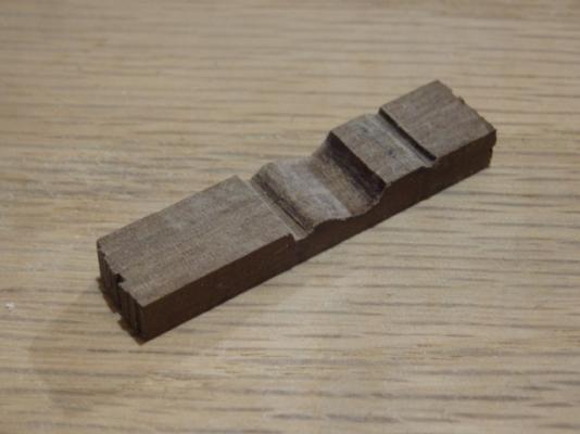
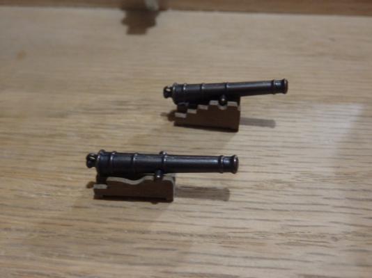
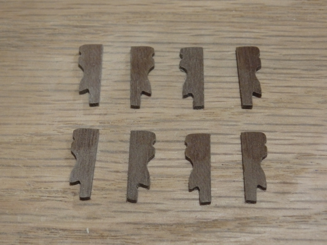
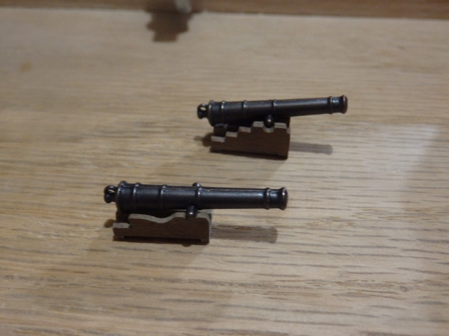
A few posts ago, Captain Steve wondered if there was a way to make the cannon carriages on the Dragon more authentic than those provided in the kit. I decided to try and scratch out the carriages using a picture I found on the web as a reference. I also wanted to lower the height of the cannons to better center the cannons in the ports.
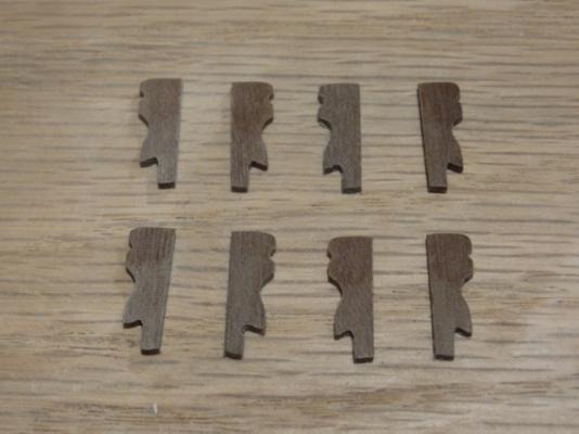
Carriages were made by gluing eight 5mm walnut strips together and then slowly filing out the carriage shape using my needle files. After cutting the excess wood away, the glue was then loosened by soaking in water overnight to separate the pieces. The carriages were then assembled using another piece of 5mm walnut as the base and 1mm wide walnut strips to form the feet. I hope the finished prototype looks OK and certainly a little different from the kit carriages.
In other news, the Admiral and Captain looked after me this Father's Day and the Lady Confederacy has now docked in Saratoga Springs!
 . Be a while before I start her as I must finish my Dragon first!
Thumbnails below and thanks for reading.
Cheers,
Nigel.

- RichardG, Dimitris71, CaptainSteve and 6 others
-
9
-
Hi Nigel,
I think we all struggle with finding a good work-life balance at times...I certainly do, especially whenever I ramp up on a new project. Whatever changes you decide to make in the end, I know your Mordaunt will continue to be a spectacular build.
So, like everyone else, I will just wait patiently to enjoy your next update.
Cheers,
Nigel.
-
-
Congratulations Mark! Your last fix made quite a difference between dropping the passes while holding the power and increasing speed. New carving looks great. Hopefully your new learning also helps Debbie and Charles.
Hope you can now just enjoy using your new tool!
Cheers!
Nigel.
-
Hi Mark,
I was thinking more about your issues as well as Debbie and Charles after re-reading latest posts. You both have faced the same basic issues but their level if anything seems more severe as they aren't matching your results, even after similar debug efforts. Not sure I can suggest much new, but thoughts below.
As the quality control on these tools can only be described as poor at best, I am wondering if your lasers have their reflectors and output couplers correctly aligned. I would expect these would be factory set and probably aren't user adjustable on a unit sold for use by even technically very aware buyers like yourselves. Net would be markedly lower output so even well aligned optics post laser could not compensate, leading to the use of much higher power settings. Could have been a bad production run so it may be worth asking for a replacement laser assembly to test this idea out as you seem to have have worked through every other likely alignment option. Check for a much later serial number on any new unit so you know the manufacturing dates are well separated.
I also know you will be doing your checks carefully, but please watch the material, power handling as well as the optical specs if you try different lenses. These lasers need careful matching to their optics given the power outputs.
As for MM, my thought is they are probably out of their depth and don't have the training yet to really support this tool. Working with you on this debug is a good way to learn and train their staff. They should be grabbing the chance...I know I would given the tools' potential.
Finally, I hope you don't take this amiss, but please be very careful as you debug things. I expect the tool is fully interlocked for safety, shutting off the laser as the tool is opened and so on, but like many tools, these lasers can be very dangerous. There is an old, but actually rather non-funny, joke on the wall in most labs I've worked in where lasers were used, especially in labs with open beams . "Do not look into the laser with your one remaining eye".
Stay safe!
Cheers,
Nigel.
- DJones, thibaultron, Jack12477 and 2 others
-
5
-
Hi Mark,
Great progress...windows are especially beautiful and the carvings look like they just need the char removing and then some relief adding to finish them off. I do see what you mean about adding some margin to allow for charring on the really thin details.
Looks like all your hard work is paying off and potential is really there. A pity the manufacturer can't deliver this capability level out of the box and provide the level of tech support needed to help their customers come up the learning curve smoothly.
Cheers,
Nigel.
-
-
Hi Mark,
Bringing up any optical based tool is tough and it is even harder when the customer service is poor. Your tests do show the promise the tool has to do some really detailed work.
Couple more thoughts in case they help. Consider checking how level the stage is in the x and y directions and also if the laser head is perpendicular. Any tilts could make finding a clean focus point across the piece more difficult. I also don't know how much adjustment you have to control the scan speed. Slowing the scan speed should allow the laser power to be dialed down and perhaps help reduce the charing. Sometimes slower translations speeds also help to reduce any vibrations back into the optics as well. Every little can help.
Cheering you on from afar... good luck!
Cheers!
Nigel.
-
Hi Mark,
So to combine your feedback and Petes, it seems I should be shooting for about 1/32 in of margin per side to the lines rather than the 1/16 in I did on the first frame. More than that could cause problems during fairing as well as generate a small duststorm in upstate NY!
. Will go for my first frame in boxwood once I get back from vacation (
...happy dance time!) I'll also get those tempered glass plates. Thanks again for all the great feedback...
Cheers,
Nigel.
-
Hi Pete,
Thanks for the heads up on leaving more on the frames...I thought I had left enough at about 1/16in on the test frame on both inside and outside edges.
Is an 1/8 in a more realistic target?
Thanks for the likes everyone.
Cheers,
Nigel.
-
Hi Nils,
Been enjoying following along and lovely work as everyone else has said.
Stringers are really showing up the beautiful hull lines.
Cheers,
Nigel.
- Piet and Mirabell61
-
2
-
Hi Augie,
Thanks for looking in...expect this to be a very slow voyage but fun.
Hi Mark,
Thanks for the tip on letting the futtocks cure between glass to prevent warping. My test frame looks true, but who knows what will happen next time so I will definitely add this step in. Please keep any advice coming...it is much appreciated!
Cheers,
Nigel.
- pythagoras and mtaylor
-
2
-
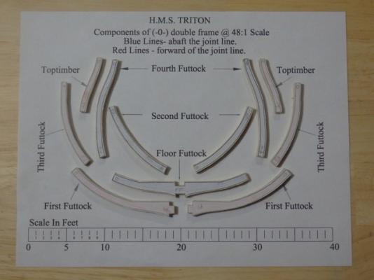
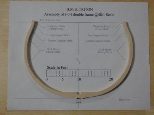
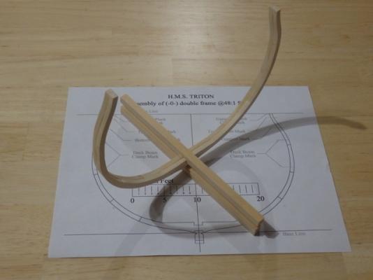
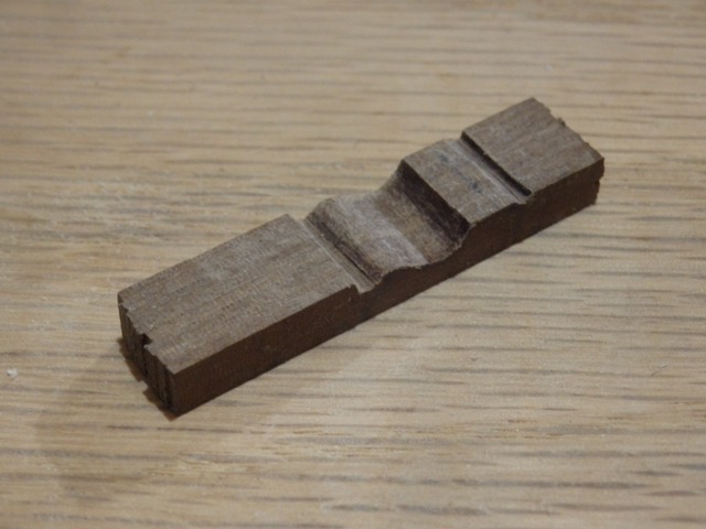
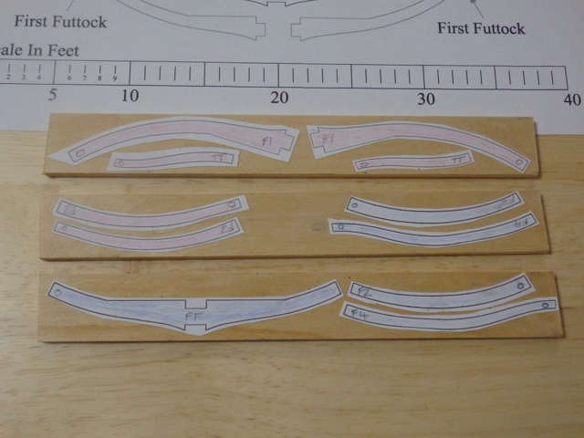
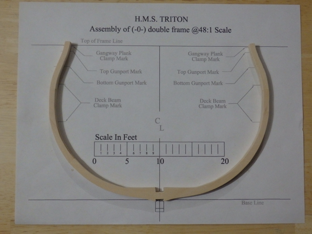
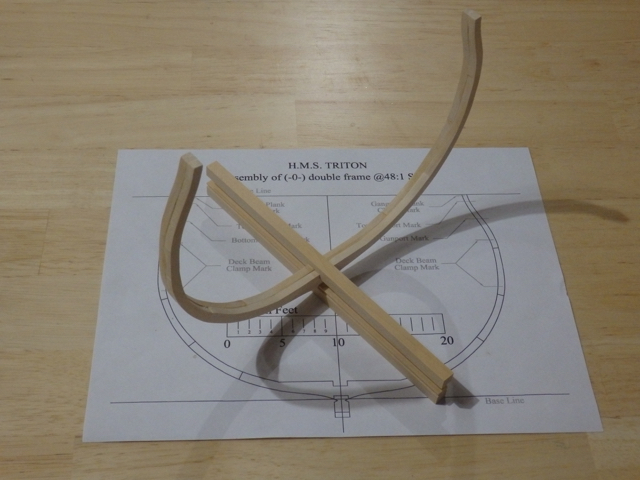
Hi All,
So, I started to make some sawdust by doing a test frame. The templates were cut out and glued onto basswood…I had to color code them as of course the printer decided it was out of color ink again! The futtocks and top timbers were cut out using my coping saw staying well clear of the outer lines. I then had to do a fair amount of sanding to get to ~1/16 in of the outer line and so leave some fairing margin. Floor and first futtock notches were cut out using a razor saw and cleaned out using a chisel before filing the notch smooth. Components were then glued up following the assembly sheet and then were given a light sand with 320 grit paper to clean them up.Never tried something like this before so overall pretty happy with how my test frame turned out. Feedback would be much appreciated if anyone sees anything amiss that would cause problems later on in the build.Thumbnails below.Cheers,Nigel.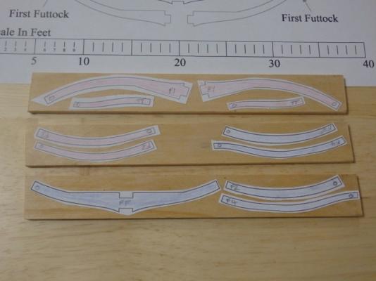
-
Hi Bob,
Just fabulous and congratulations.
I was a late arrival in following your build, but can now look forward to following along with your Cutter Cheerful build from the start.
Cheers,
Nigel.
-
Hi Mark,
Very interesting and great you have got the tool running and getting good results. Thank you for posting.
Having worked quite a bit w optics and lasers, if you haven't already, perhaps consider checking the replacement laser cost before you decide if you will hold onto this unit. Seems you will be running multiple passes and/or at high power so tube life could be an issue. Also, keep plugging away on the focus part....even very small alignment tweaks will make a huge difference to the laser focus point. Finally, if the optics fixtures have any flexure and/or have poor fine adjustment and lock capability in all directions including rotation, regular re-alignment may be a continued headache as things will drift as you load/unload your unit.
Good luck and looking forward to you next update!
Cheers,
Nigel.
-
-
Hi Danny,
Been following along from the back row. To echo what all above have already said...just gorgeous work.
I also just want to say thank you for posting this method. Exactly what this newbie needed as a guide as I try to scratch out a ships boat to replace what came in my kit.
Cheers,
Nigel.
-

Mediterranean Sea Boat by IgorSky - FINISHED - Scale 1/200 - BOTTLE
in - Build logs for subjects built 1901 - Present Day
Posted
Hi Igor,
I've never watched a ship in a bottle being made before so I'll follow along if you don't mind.
The hull looks fantastic!
Cheers,
Nigel.