trippwj
-
Posts
3,156 -
Joined
-
Last visited
Content Type
Profiles
Forums
Gallery
Events
Everything posted by trippwj
-
 Think I'll buy a ticket for this show as well!
 -
t's tradition... but without the adult beverages and great food of St. Patrick's Day and Cinco de Mayo. You are obviously not of Italian heritage, Mark. In the old 'hood, there abundant adult beverages. Of course, the families all came over in the early 1900's. I will need to see if I can find it, but the Congressional Research Service recently released a brief report on Federal holidays that had some info on the history of Columbus Day. Became a Federal holiday in 1937. It would require an act of congress to un-holiday the day. I think the allure of Columbus is it reflects the spirit of exploration, where even a failed expedition results in something new. There are many tantalizing tidbits that may indicate an earlier visit to North America than 1492, but Columbus had an effective PR and marketing firm. As to not making it to the continent - he did not have a visa and Customs wouldn't let him land.... Blaming Columbus for the actions of his sponsoring government is like blaming the pilgrims for the Red Sox trading Babe Ruth.
-
Schooner plank length
trippwj replied to riverboat's topic in Building, Framing, Planking and plating a ships hull and deck
No problem, Frank. Your 12 inches = 25 feet is also accurate. -
Schooner plank length
trippwj replied to riverboat's topic in Building, Framing, Planking and plating a ships hull and deck
The range from Russ sounds about right. The term "Cutter" has nothing to do with rig or form but rather function. It is a Revenue Cutter - a term still used today to describe the Coast Guard fleet. -
I think either approach would make sense! They were both based on the 51 ton plans by Doughty. The following is extracted from US Coast Guard and Revenue Cutters, 1790-1935 by Donald L. Canney (1995). Note that he is the source for many of the older cutter records at the USCG History site, and is generally considered to be authoritative with thoroughly researched information. Both cutters were built by A. & N. Brown in New York. In terms of history, the Dallas served longer with numerous captures over the years (including at least 2 large slavers). The Surprise, however, lived a very short life. She was found to be too deep for service in Charleston, SC and was sent to Norfolk VA where she was sold in 1817.
- 78 replies
-
- 2
-

-
- dallas
- artesania latina
- (and 1 more)
-
As has been said already - nice job on them thar ports. While on the other side of the continent from Mark, getting a chilly rain all day here today as well, so much progress in the shipyard. Enjoy the summer weather tomorrow!
- 1,616 replies
-
- 1
-
-
- caldercraft
- agamemnon
- (and 1 more)
-
"tis indeed a challenge. There have been some discussions in the past which point out that the "perfect" alignment was likely less common than portrayed - it is a lot easier to paint them in a row than as they may have actually been on the ship. The Captain, Bosssun and sailing master would make adjustments to improve the trim, adjust the rake, or accommodate damage from storms, so the deadeyes would likely form a near- straight line as opposed to an actual straight line. I have seen some folks do an amazing job reeving the deadeyes off the hull - would need to do some real digging to show you the examples, but they are there. I guess one part of the equation is historical accuracy - for accurate termination of the lanyards, they are tucked through and around the shroud. If you can terminate the lanyard with, perhaps, a dollop of glue at the top of the deadeye, then you can install the shroud, get the right tension and the tie off the lanyard around the shroud.
-
Can be done, but the challenge is the shroud is where the lanyard gets tied. Getting the tension right by adjusting the shroud would be the big challenge, but not insurmountable.
-
While looking through some older Nautical materials I had downloaded, I came across the attached series of articles from The U. S. Nautical Magazine and Naval Journal from 1857 discussing the competition that resulted in William Webb building the Harriet Lane. Rather interesting set of specifications spelled out in the requirements article, closely matching the HL. Also a peek into the politics of the times! Never know what you will find in these old journals! Note that the article with a description of the proposed Revenue Cutter was by John Griffiths - one of the losing bidders, and also (coincidentally) the publisher and editor of the magazine. It is interesting to see how closely many of the dimensions and fittings align with the winning model proposed by Webb. Pages from 1857 Monthly_Nautical_Magazine_and_Quarterly.pdf
-
What they said! Those colours look great!
-
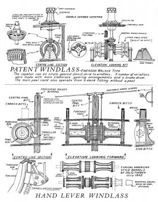
Both a capstan and a windlass showing on the plans from grant. Here is a drawing from China Tea Clippers by George Campbell (1954) of both a capstan and a windlass.
-
Based on the information from the USCG historian, the Dallas was a very shallow draft cutter, drawing 6 feet. TYPE/RIG/CLASS: Topsail schooner / Surprise Class COMMISSIONED: 1816 DECOMMISSIONED: Sold, 1821 DISPLACEMENT: 51 3/95 tons PROPULSION: Sail LENGTH: 56’8" BEAM: 17’ DRAFT: 6’ Dallas1816.pdf
- 78 replies
-
- 4
-
-
- dallas
- artesania latina
- (and 1 more)
-
Attached is an article from 1831 showing a compound capstan. Can also be found via Google books at http://books.google.co.uk/books/about/Transactions_of_the_Society_Instituted_a.html?id=mlQ1AAAAMAAJ 1831 COMPOUND CAPSTAN.pdf
-
Looking good, Sal - nice job on this boat!
-
All I can say is WOW! That is some very impressive detail work, Sherry. Nicely done!
-
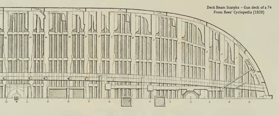
Deck beam Scarphs?
trippwj replied to NMBROOK's topic in Building, Framing, Planking and plating a ships hull and deck
Thought I would throw in an illustration from Rees' Cyclopedia (1820) of the deck beam scarphing on a 74 gun ship.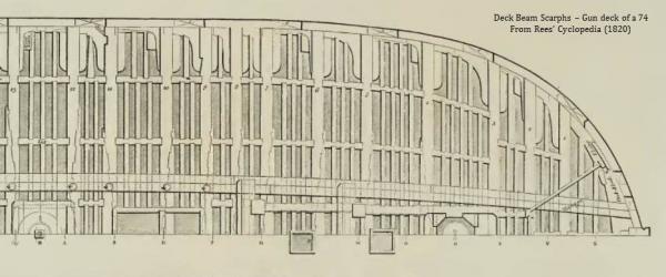
-
177x ships - British vs US design, what are the differences?
trippwj replied to Mike Y's topic in Nautical/Naval History
Well put, Jason, and there is the essence of the issue - at the time in question (177x), there was no true American "Admiralty" to make those decisions - they issued general requirements to purchase "Sloops" or "Schooners", then for some "Frigates". Individual colonies then also had vessels built, but to no set mold or designs. The first effort at a standard design criteria wasn't until the first 6 frigates were ordered in the 1790's - and even those, whilst built based on the model and preliminary draughts by Humphreys, varied dramatically in final product, influenced by the builders personal vision and the Naval Captain (assigned to each as superintendent during construction). Add to that the subscription built vessels (such as the Essex) which were totally designed and built based on the local contract - then sold to the Federal government when completed. The concept of a standardized naval construction program - plans, materials, methods and so on - was much slower to take root in America, partly a result of our desire for "States Rights" during the earliest days of the Republic, and also a general mistrust of central government. -
Hi, Sal - good question! I have also posted a response to your build log. In this case, it appears that the ship sat lower at the stern than the bow - not at all uncommon for these types. Increased speed, supposedly, as well as providing the rudder more bite and increased stability. The launch ways are angled to allow the ship to slide into the water - think of them in relation to the ground and the keel is parallel to the ways. 2.5 to 3.5 degrees was very common for launching ways - about the ideal slant to let the vessel slide in a controlled manner into the water, but not so much that she would start to move before the blocks were removed. The waterline is in reference to the way the ship will set in the water and will not match the slant of the ways. In the water, the stern would be lower, hence that 4.5 degree angle as opposed to the ways. They are really two totally different and unrelated sets of angles. the masts also showed different amounts of "rake" - in general, the fore mast had slightly less rake or angle than the aft (main) mast. This was very common across nearly all ship types.
-
177x ships - British vs US design, what are the differences?
trippwj replied to Mike Y's topic in Nautical/Naval History
Those are good points, Bart. I guess I was thinking more of folks like Joshua Humphreys. In his youth, he was a ship carpenter’s apprentice in Philadelphia, and after the death of the master, Humphreys was given control of the ship yard. His later creation of his own ship yard made him well-known in the colonies as a naval architect, and he was commissioned by the U. S. government in 1776 to build ships in Philadelphia and prepare them for the Revolutionary War. As I recollect, he did not visit Britain prior to the start of the 1800's, if at all. Many of the New England ship builders actually had closer ties to French influence (Canadian influence) and Irish than strict British practice. In fact, when you look at ship yards such as Portsmouth NH while the builders had British ancestry, they had been in New Hampshire since the mid 1600's - whatever influence came from Britain would have been long since diluted by the local maritime environment and nature of the fisheries and mercantile activities from those regions. See (for example) Preble's History of the United States Navy-yard, Portsmouth, N. H. (1892). In the Historical Society records for this region, the early permanent settlers of this part of Maine were from Massachusetts - and had been there for many years. The records on ship builders I have seen so far are for locally trained folks - they started building their own boats for fishing (patterned after the French, Portuguese, Spanish and British vessels in the Newfoundland/Bay of Fundy fisheries) but to their own preference. These evolved into privateers and merchant vessels in response to market pressures (for lack of a better phrase). While there were similarities to boats built in Massachusetts and New Hampshire, they also had some unique characteristics that set them apart. -
Hi, sal - good question! In this case, it appears that the ship sat lower at the stern than the bow - not at all uncommon for these types. Increased speed, supposedly, as well as providing the rudder more bite and increased stability. The launch ways are angled to allow the ship to slide into the water - think of them in relation to the ground and the keel is parallel to the ways. The waterline is in reference to the way the ship will set in the water and will not match the slant of the ways. In the water, the stern would be lower, hence that 4.5 degree angle as opposed to the ways. They are really two totally different and unrelated sets of angles.
-
177x ships - British vs US design, what are the differences?
trippwj replied to Mike Y's topic in Nautical/Naval History
In thinking about the timber for masts, the British had been using New England (particularly Maine) trees for masts and spars for many years - see The Kings Broad Arrow for some good information. As to a side by side comparison, I have not seen any good comparisons. Below are a brief comparison of the British fifth Rate HMS Lark of 32 guns and the Continental Navy Frigate Randolph of 32 guns. have not done any digging yet for mast and rigging details - doubtful there is much for the Randolph unless in a painting somewhere. Class & type: British Richmond-class fifth-rate frigate HMS Lark Built in 1761-62 Tons burthen: 680 61⁄94 bm Length: 127 ft 2 in (38.76 m) (gundeck) 108 ft 0.375 in (32.92793 m) (keel) Beam: 34 ft 5 in (10.49 m) Depth of hold: 12 ft 0.5 in (3.670 m) Sail plan: Full-rigged ship Complement: 210 officers and men Armament: 32 guns comprising Upperdeck: 26 × 12-pounder guns Quarterdeck: 4 × 6-pounder guns Forecastle: 2 × 6-pounder guns Type: Continental Navy Frigate Randolph Built in 1776 by Wharton & Humphreys (Philadelphia) Designed by Joshua Humphreys Length: 132 ft 9 in (40.46 m) Beam: 34 ft 6 in (10.52 m) Draft: 18 ft (5.5 m) Depth: 10 ft 6 in (3.20 m) Armament: 26 x 12 pdrs; 10 x 6 pdrs -
well done, Slog. Your turn!
-
Sorry, Jan - wrong fish! While this vessel was not from Eastport, it was an important part of a fishery which at one time was concentrated in Eastport, Maine. Small fish - big money back in the day!
-
177x ships - British vs US design, what are the differences?
trippwj replied to Mike Y's topic in Nautical/Naval History
While the arrangement of spaces would be similar, each ship would be unique as there was no standard in the Colonies. With very few exceptions, the American ship builders were not experienced with war ships - they built merchant and fishing vessels. As to framing, very few had any knowledge of the British Establishment, and not many had been trained in British yards. Many were self taught - learned the skills in a yard but little formal training. Each had institutional knowledge to guide him, not written rules. -
Deck beam Scarphs?
trippwj replied to NMBROOK's topic in Building, Framing, Planking and plating a ships hull and deck
Recognizing that these are from a much later era than the original query, here are a couple of snippets from Fincham (1825) - An Introductory Outline of the Practice of Ship-building available via Google Books in PDF (I have not been able to locate an edition with the plates as yet but continue to seek same) Concerning the Keel (Fincham, 1825 – page 9) 4. As the keel cannot be obtained in one piece, as to length, several pieces are bolted together lengthways, by what-is called a side or vertical coak scarph; the scarphs being in length about three times the depth of the keel. The coaks are for the support of the bolts, especially to resist the strain when the butts of the scarphs are being caulked; they are one-half the length of the scarph, and their breadth one-third its depth. . 5. The scarphs are bolted with from six to eight bolts; eight, from frigates upwards, and six to smaller vessels: half of the bolts are driven from each lip side, with a ring upon the head, and clenched upon a ring on the opposite side. . 6. The French and most other nations have flat or horizontal scarphs; but as these scarphs tend to weaken the keel, in the direction in which it is most subject to strain, more than the side scarphs, the English mode is preferable; for the keel bends vertically, which brings a tension on the upper or lower fibres, according as hogging or sagging takes place, which fibres are cut off, in a greater number in these scarphs, to let in the lips; and when sagging takes place there is a tendency to open the joint at the lower lip; this opening will cause the scarphs to leak, except a stopwater be placed at the intersection of the joint of the scarph with the outer edge of the garboard seam, or by increasing the length of the scarphs. Concerning Deck beams (Fincham, 1825 page 70) – 169. The beams are distinguished into single pieces, two ( b ), three ( c ), and sometimes four piece beams (f and g): the length of the beams and the timbers that can be provided to make them will determine the number of pieces they are to be composed of, which should always be as few as possible; for the quantity of timber required to make them will be increased with the number of pieces, because the number of scarphs is increased. 170. When a beam is made or composed of more than one piece, the pieces are united together with vertical scarphs. If in two pieces ( b ), the scarph is 1/3, if in three pieces ( c ) 1/4, and when in four pieces (f and g) 1/5 the length of the beam. 171. The scarphs are distinguished into right and left hand scarphs, and are named by the hand that is on the side of the angle, or the side from which the wood to form the scarph is taken off; when at the side end, the face is towards the scarph and looking upon the upper surface; they are bo1ted with from seven to nine bolts; so as to make their distances apart from 16 to 18 inches, placed alternately. about 2 1/2 to 3 1/2 inches from the upper and lower part of the beams. An equal number of them is driven from each lip side and clenched upon the opposite; in addition to these bolts, one nail is driven into each lip on the opposite edge to the nearest bolt, and one bolt is frequently driven up and down in each lip to prevent its splitting.