trippwj
-
Posts
3,156 -
Joined
-
Last visited
Content Type
Profiles
Forums
Gallery
Events
Everything posted by trippwj
-
 Dangit, Mobbsie - I hoped no one would notice! You know how I hate planking the hul, but guess I gotta do it now. Appreciate the kind words, Adam. Will see if the bones look as good when I get done with the interior work! Now, Sjors, it isn't that I couldn't find my way to the workshop, I just couldn't get the time to spend IN the workshop!!! Thanks, Popeye - me, too!!!!
 -
Thanks, Bob - it works well having a variety of water access around the island. Thanks - now I just need to talk the boss lady into the idea! I, too, am looking forward to finding out how I finish the cabin! Thanks for the kind words, John. I have been amazed at how much enjoyment there is on this little POF kit - it is a challenge, but there are so many possibilities for making it "my own". Thank you, Frank - will see if you still say that after my next update!
-
ooops!
-
Greg - I believe this is the article he is describing. http://www.duckworksmagazine.com/10/columns/austin/05/index.htm
-
Good morning, Denis. Things are looking mighty fine on there - as always! Somehow it seems so obvious when I see you create these odd shaped pieces - as for me, I guess my mind just doesn't work the same way - I sit there scratching my head over much more mundane pieces that aren't clear from the plans. Carry on, my good man - looking forward to the next episode! Regards -
-
Those cannon look wonderful - love the subtle tones in them!
-
Yikes! Where will this beastie live when you finish her??? Looks truly amazing, Kevin. Hope you have a room with a very high ceiling in the house!
- 1,319 replies
-
- 2
-

-
- caldercraft
- Victory
- (and 1 more)
-
A resource which, while not online, may be of use is the William L. Crothers Collection at the G. W. Blunt White Library, Mystic Seaport (http://library.mysticseaport.org/manuscripts/coll/coll282.cfm ) Brief Description: Papers and volumes resulting from Crothers' extensive research into the history, use and details of flags as used by the American merchant marine. Includes a "Directory of Private Signals Flown by American Merchant Sail" which contains an index of colored flags. The collection also includes two illustrated volumes detailing the history of the flag hoist signal system, as well as the related correspondence and references upon which Mr. Crothers based his work.
-
This looks like a neat variation - while it could be viewed as POB, it actually appears to use the bulkheads installed somewhat like the Hahn POF approach, with a keel, stem and stern attached more in line with actual ship building rather than as part of a centerline former for the bulkheads. Reminds me in some ways of the "plug" method of building smaller boats, although in this case the plug is kept not replaced with frames.
-
Not sure how it would have been done in New York Harbor of 1868 or so. This would have been right at the end of the period when Captain Frederick Marryat's Signal Flag Code was in use (note it was specifically developed for merchant vessels). The International Code of Signals was first drafted in 1855. This system was first published as an international and a British volume in 1857 and gradually adopted by most seafaring nations. See http://www.pem.org/sites/archives/guides/signals.htm for a brief descriptive overview (though there are no details). The International Code of Signals for 1909 is available at https://archive.org/details/cu31924030898351 The 1854 update to Marryat is at http://books.google.com/books?id=jGEBAAAAQAAJ The 10th edition (1847) can be found here: http://books.google.com/books?id=LtsDAAAAQAAJ
-
Size of planks on a 18th century ship
trippwj replied to Captain Al's topic in Nautical/Naval History
Here is how Humphreys proposed the external planking for the 44 gun frigates (almost identical for the 36 gun frigates) - Main Wales Six strakes on each side 7 inch thick and 10 inches wide Black Strakes 5 in number the first and second 5 ½ inches thick, 3rd 5 ¼ inches, 4th 5 inch and the 5th 4 ½ inch by 10 inch wide. The upper edge of the black streak to be mitered down to a level in order to carry the water out of the seam. Plank between the black streak and the string to be 3 ½ inch thick. Thick stuff under the wale. First streak 6 inch thick, 2nd 5 ½ inch, 3rd 5 inch and 4th 4 ½ inch running plank in the bottom 4 inch thick to be not less than 6 feet scarph nor less than 4 strakes between every two bolts on the same timber. The seams to be made all a little outgauged. Running plank on the bottom Great care must be taken to run to a bevel both edges of the plank that comes together alike for if one edge is hewn standing the other must be under which makes bad work. The plank with the under bevelling will caulk off. Bilge strakes outside 1 of 6 inch thick, 2 of 5 ½ inch thick, 2 of 4 ½ inch thick. On each side the middle streak to cover the butts of the timbers equally inside and out to be reduced fore and after ends the same as the running planks. -
Keel taper
trippwj replied to Redshirt's topic in Building, Framing, Planking and plating a ships hull and deck
While the following doesn't provide any guidance on where the tapering starts, here is an example of how the keel, stem and stern post for a US 44 gun frigate of 1794 were described - Keel - sided 17inches stem and post 19 inches midships Stem - in 2 pieces, sided 17 inches, Stern post - 18 inches square at the head, sided 17 inches 3 1/2 feet below, etc. Inner post - sided 20 to 24 inches at the head and 12 inches at the keel. Keel of good sound white oak in 3 pieces. The middle piece to be not less than 80 feet if to be had. Scarphs not less than 12 feet to be kept clear of the main and fore steps sided in the midships 19 inches at the stem & post 17 inches and as deep as can be had. The scarphs all to be tabled and bolted with 5 bolts 1 1/8 inch diameter. False keel 6 inches thick but not to be put on until after the floor & keelson bolts are drove and riveted. Stem in two pieces if to be had the lower one of good white oak sided 17 inches and moulded not less than 12 inches clear of the rabbet scarphs not less than 4 feet to be tabled and bolted with 3 bolts 1 1/8 inch diameter. Stern post 18 inches square at the head sided 17 inches below by 3 ½ feet fore & aft including false posts and 10 inches thick on the aft side at the keel to be fitted for a crooked headed rudder. Inner posts to be 12 inches for & aft to run from the transom to the keel to be of live oak sided at head from 20 to 24 inches and at keel 12 inches. Wayne -
Wow, Bob - very nice job on those bits. The details look spot-on, and the cathead supports look amazing. So - have you done carving before? If your sculpey work is anything like your wood work, that figure head will be a piece of art!
-
What a fantastic looking ship! Very nicely done! What are you contemplating for the ultimate stand?
- 555 replies
-
- 1
-
-
- sovereign of the seas
- mantua
- (and 1 more)
-
Superb job on the copper, Sjors. I will let you know when it is time to copper the Essex - will set aside the guest hammock for you when you come over to do it!!!
- 1,616 replies
-
- 1
-
-
- caldercraft
- agamemnon
- (and 1 more)
-
Lack of math skills - anyone could measure the circumference, but you needed to convert that to get the diameter. Most sailors and shipyard workers had little or no arithmetic - which is also why there is generally a rather large section on math is the early books on shipbuilding and naval architecture.
-
Beautiful work, Kevin - the sunlight brings out the true colors so nicely!
- 1,319 replies
-
- 1
-
-
- caldercraft
- Victory
- (and 1 more)
-
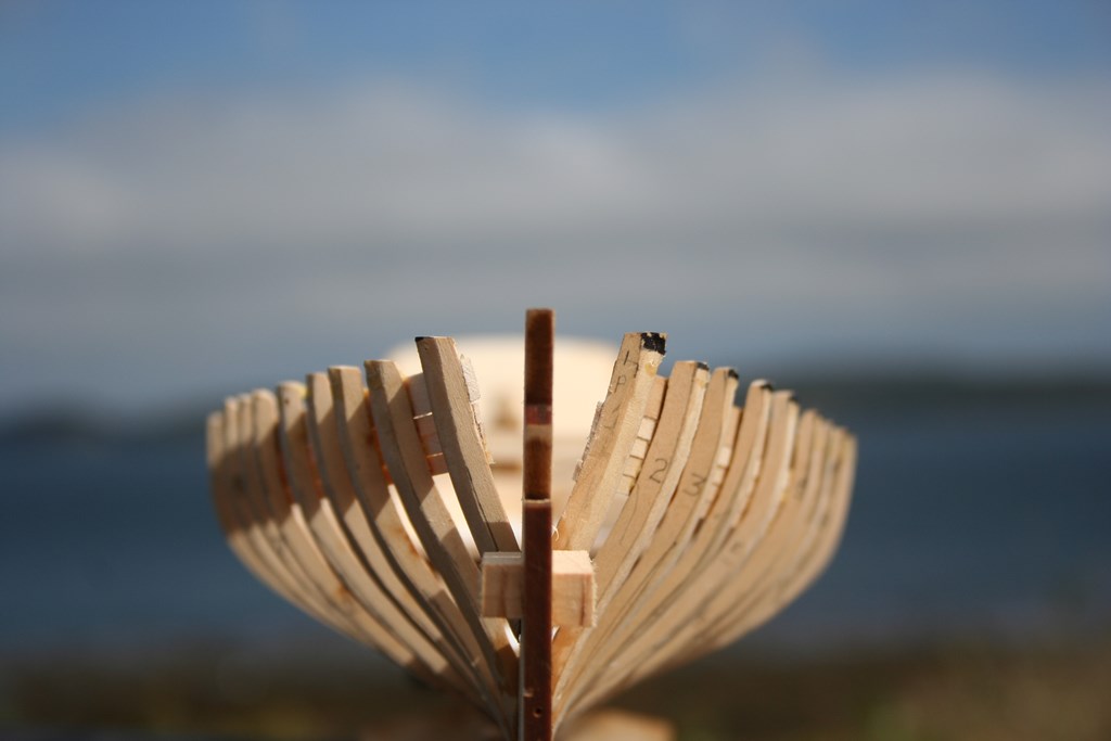
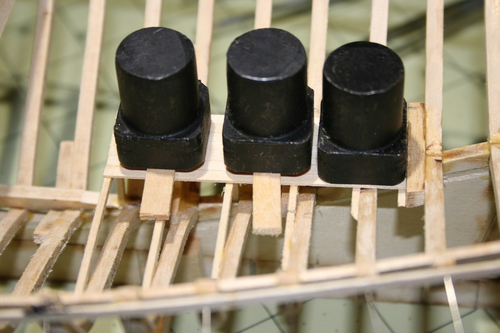
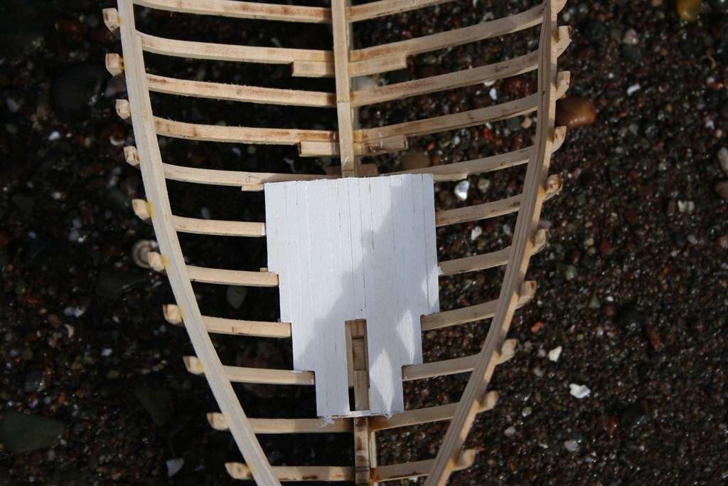
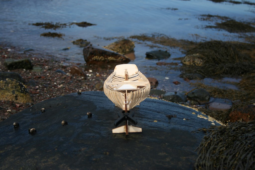
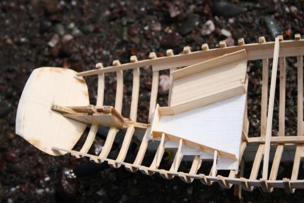
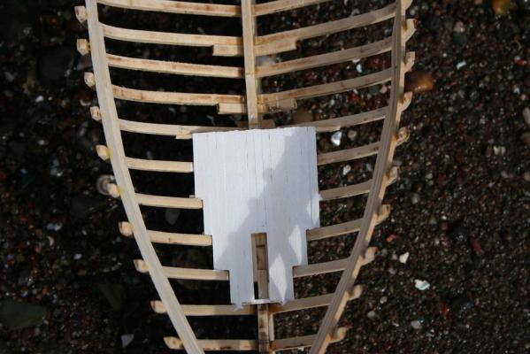
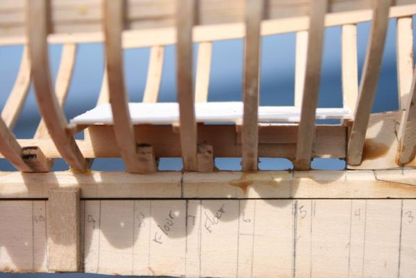
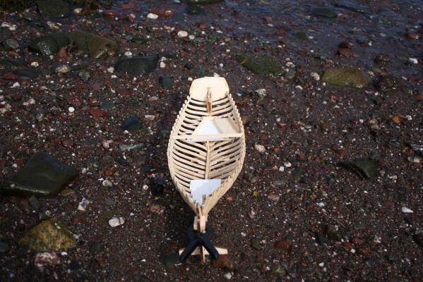
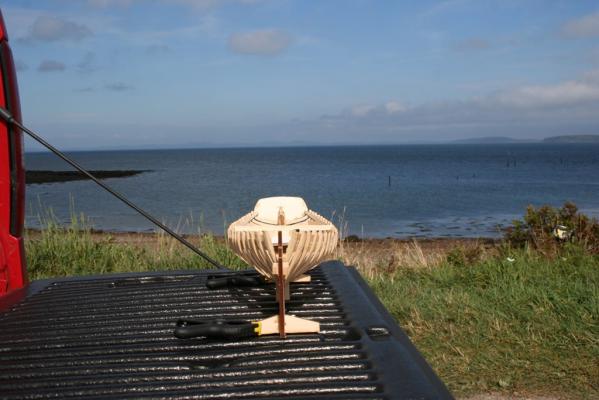
Good day one and all - I hope you have been enjoying the last day before the autumnal equinox (or, for our colleagues on t'other side of the equator, the spring equinox). WIth both boys gone (one back to Arkansas for the school year and the other moved into a college dorm), have gotten what, for me at least, is a lot done on the ECB. Last post I was just installing the posts and beams for the cabin sole. Here are a couple of shots of the process. Used the heavy "plugs" from the workbench as weights to install the sole planking. Worked quite nicely! Also built out the supports and laid the port side bunk and back "wall". Still some finish sanding to do, then prime and paint. The sole and bunks will be grey and the "wall: white. Not sure what color to do the overhead when I get to that stage. Similar process for the forecastle sole. As you can see in the following, I have also started to install the ceiling planks - I am using a 4-butt pattern, scale legnth, top plank is 20 feet (max length I am using for the planks). Here is a good view of the bow framing - still some cleanup to do, and those with the black marking a a tad strong and will likely need to be trimmed when I get the deck beams installed. And, lastly, the token scenic view looking over Passamaquoddy Bay. So, next steps are to continue with the starboard side bunk, then tackle the wetwell. I will be keeping the midship section on the starboard side partially un-planked, including the ceiling, to allow a view inside. The cabin will have a bulkhead closing off the forward end, so will be leaving off some of the planks on the deck (including above the starboard bunk) to allow a view inside the cabin. Contemplating how to build a small stove for the cabin, with a brickwork base, and perhaps a small table and benches. The admiral is going to come up with some blankets for the bunks, and may see what I can find for scale cloting to hang from pegs on the forward bulkhead. At any rate, the hull seems to have held it's shape well, and be faired pretty well. I have one dip inside at frame 12 on the port side I need to fill a smidgen, and will probably need to thin that frame on the outside as well when I get to the planking. Observations, suggestions, or queries are, as always, encouraged - and greatly appreciated! Until the next time, then -


-
I think a solid hull is very respectable, and hardly a shortcut. The vast majority of models "back in the day" were solid hull type. As I recall the history of model building in the early 20th century, when the hobby developed, some of the most prominent builders - amateur and professional - preferred solid hulls. People like Charles Davis who felt that the solid hull gave you the best form for the hull. Davis, like Underhill, also worked with POB and POF, and implied what we emphasize on MSW - the goal is to build and enjoy. It matters not the medium (plastic, paper, wood, clay) nor the subject matter (so long as it be ship related, that is). The goal is personal enjoyment. Skill levels differ, but the journey - whatever the duration- is to be savor end.
-
Rick - Others can provide better examples of tools for carving the rabbet - I used a small v-blade that worked adequately, though not ideal. You definitely would be better off on this build by carving the rabbet prior to installing frames - the rabbet is pretty much aligned with the base of the frames, and for some sections will be very difficult to carve with the frame in place. Carefully measuring (and double checking) the edges before beginning carving will also aid in aligning frames when you install them.
-
Both those sites are registered to the same person - address in Haifa, Israel with email in Russian Federation.
-
Thanks, Augie. I do plan to leave off portions of the hull and deck planking - including the ceiling inside - to show off some of the interior finishing. Not quite sure how much or where, but will figure that out in time. Thanks, Grant. She is a nice looking sloop, and has a great deal of potential for individual initiative! Just hope my skills are up to the challenge! Thanks, Denis. I do plan to use scale lengths for all the planking - interior, exterior and deck. Will take longer but I think will give a better appearance. Also plan to paint her, but not sure how much just yet. My thinking right now is to display her as though she has been hauled for repairs - pretty standard for this one, I know. I am also pondering using an enlarged base for the display and to have a portion of the boatyard included. Plenty of time to make those decisions, though!