trippwj
-
Posts
3,156 -
Joined
-
Last visited
Content Type
Profiles
Forums
Gallery
Events
Everything posted by trippwj
-
 Wow, Tony. Just, simply, wow! Those spars are beautiful!!!
- 1,279 replies
-
- 1
-

-
- agamemnon
- caldercraft
- (and 1 more)
-
Thank you, kindly sir. Many many days of work remaining - I plan to detail the interior with the cabin, a wet well, possibly some other features. Those shall take me a few months I am sure. Then I start planking the hull, installing the deck beams, planking the deck and doing all the rest of the exterior - not to mention the mast and rigging part. I may have this done before Brett graduates college!
-
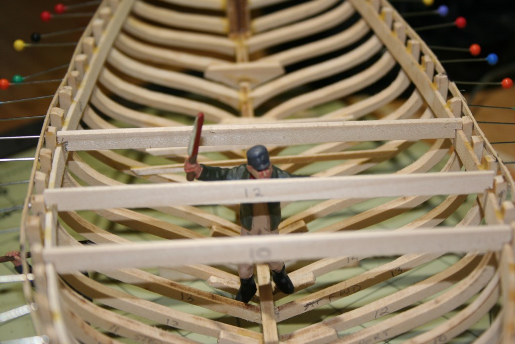
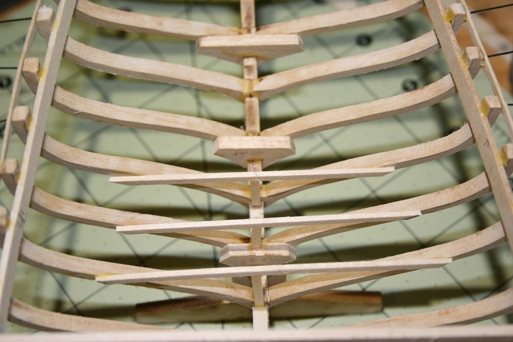
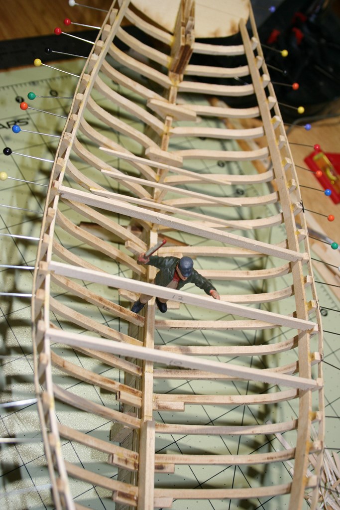
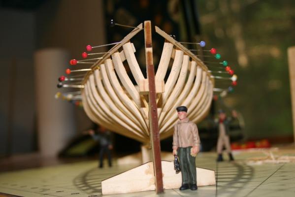
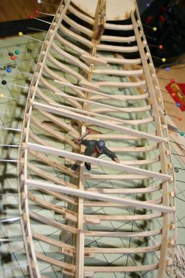
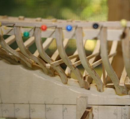
As promised, a pictorial update. I have all the frames installed, and the clamps along both sides to support the deck beams. While not necessarily correct, I opted to do the clamps in one piece for the strength it will provide vice the laminated layers with 3 sections as on the real ECB. When originally built, the clamps would probably have been in 3 sections port & starboard scarphed together, cut from 2 x 10ish timbers. You can see the clamps on either side. The foreman s checking the temporary bracing between the frames and clamps at the midship section. I also have started installing the cabin - here you can see the first 3 beams and posts for the cabin deck. there will also be beams (no posts) at frames 20 through 22. The view from above at the overall shape - remember, the outer battens that are pinned on are just temporary for stiffening, but will be somewhat useful for fairing the hull later on before planking the exterior.


-
No pictures this update, but a quick update none the less. I have added the clamps (needed to re-set one frame that was out of alignment) - nicely faired lines with the clamps in place. Have also begun to build the cabin - there are 3 posts at frames 17, 18 and 19 that support beams, then athwartship beams from frames 17 to 22. Thus far I have the posts and beams at frames 17, 18 and 19 installed and drying. The remaining beams do not have posts due to the decreasing width between frames moving aft - they just attach to the frames. My goal is to get the remaining beams installed tonight. Will add photo's when they are in.
-
Not bad, Adam. Not bad at all! The details look nice and proportional - and those colors work well. Are you adding spouts to the pumps as well? So, masting starts soon - onward and upward? Now, about those Patriot's....
-
Brian - check out the book review in the September MSBJournal for detailed info. Ian Toll is the author, originally published in 2006.
-
Batavia by *Hans* - FINISHED
trippwj replied to *Hans*'s topic in - Build logs for subjects built 1501 - 1750
Fantastic lookin ship - Very nice details!!! -
Exactly how tall is a gnome? I know where we can get pointy hats... Vivian - thank you for sharing the background on your ship. You have done her justice!
-
Looks great, Vivian! Since Sjors brought popcorn, maybe he will let you borrow his gnomes to do the rope work. Beautiful ship - details are very nice!
-
Hmmmm....obviously very nice work, impressive recall without the plans! Just pondering ur destination here....haddock? Nah, low margin. Cod? Maybe...SAWFISH!!!!
-
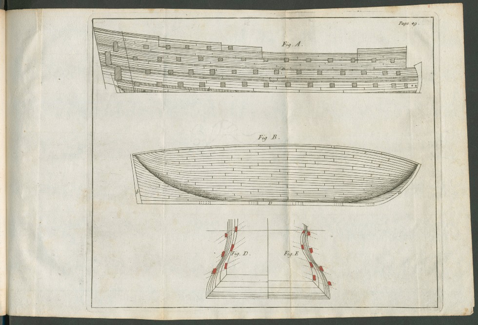
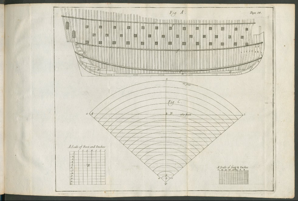
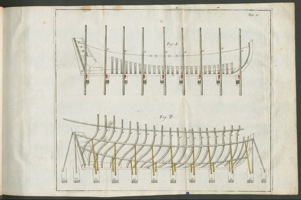
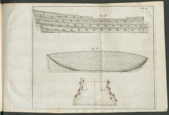
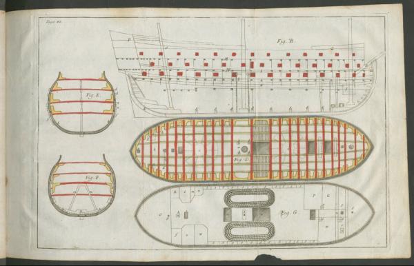
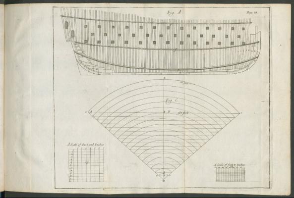
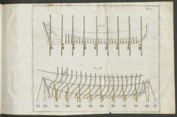
Allan - Have you seen these from Sutherland (1711) - The ship-builders assistant : or, some essays towards compleating the art of marine architecture online at http://echo.mpiwg-berlin.mpg.de/ECHOdocuView?mode=imagepath&url=/permanent/library/AE4UUGBR/pageimg Not sure if they are as detailed as others, but they are an early view of some of the framing.
-
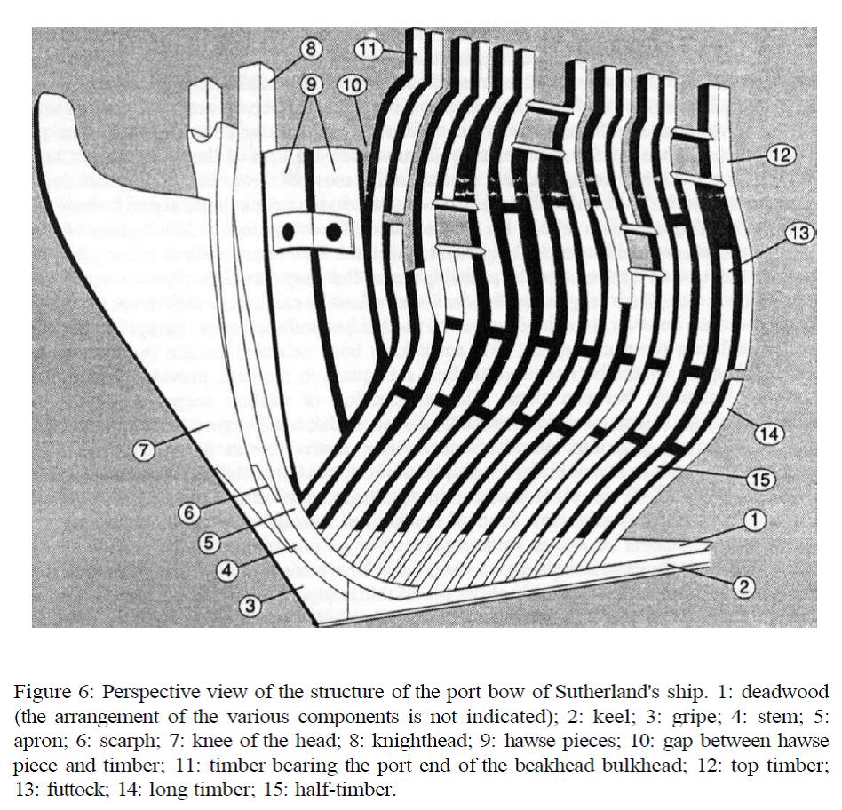
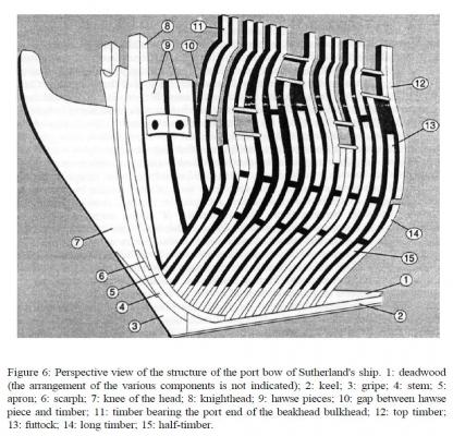
Top of the morning, Rob. Interesting observation - although Steel is quite some distance (time wise) removed from the 1719 Establishment. Looking at Sutherland is always an adventure! Have you seen the 1993 article in The Northern Mariner by Tevor Kenchington - The Structures of English Wooden Ships: William Sutherland's Ship, circa 1710? http://www.cnrs-scrn.org/northern_mariner/indices/index_vol_3_e.html It is a very interesting read as he moves through reconstructing the ship based on Sutherland and contrasting with contemporary ships and later practice. For example, see the figure below from his paper: I need to do some digging through some of my transcriptions of Humphreys notes, but there was one circular concerning altering the frames in the way of some of the gunports on the frigates. Will see if I can find that and post it when I get a moment. So, having said all that, I really am not sure how to take the framing as drawn by Steel. On the one hand, it would seem to indicate that at least a couple of ports were cut on the bias to the frames - which would indicate potential weakening of the frame. It would also then appear to indicate the desired angle for the gun as being directed less forward (the orientation of the port opening) - keeping the gun nicely aligned with the rest. On the other hand, looking at Rees' Plates II and III (I believe they are the same as Steel's), it doesn't appear that the frame timber is reduced in the way of the port. Very strange! Let me see if I can find the information from Humphreys and will post it later today. Thanks for asking these questions - it is an interesting exercise not only in design but also geometry!!!!!
-
Looks fantastic, Sjors. VERY impressive! You know, just thinking out loud here, but if you set the starboard side toward the wall, you won't need to bother with all that pesky copper on the other side and can move on to other work. Again, you know, just thinking outside the box a bit....
- 1,616 replies
-
- 3
-
-
- caldercraft
- agamemnon
- (and 1 more)
-
Very clever, Adam. The pumps look snazzy. Glad you are getting some time in the shop - it can be quite therapeutic!
-
Off to a good start!
-
Most references I have seen show the from Fore to Aft on the Starboard and Aft to Forward on the Port side. They should start in the left hole looking at the deadeye from the inboard side (or the right hole from the outside looking in).
-
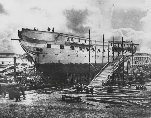
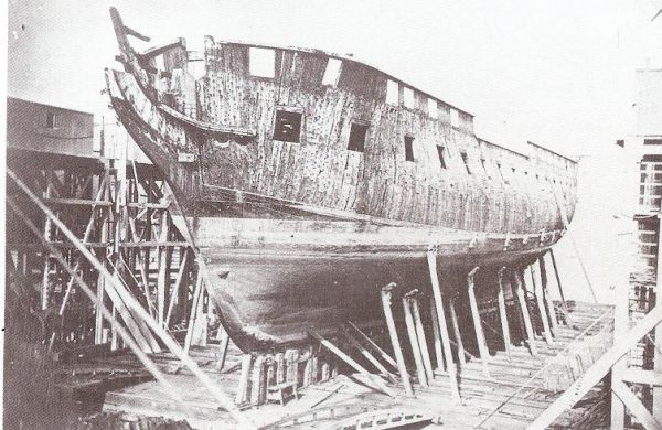
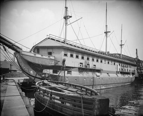
Good morning, Rob. Let me do some digging - I know that the documents I looked at all refer to square ports (a single dimension given for the size inside the port fore & aft and a single dimension up & down). The plans also show them following the external hull shape with a square opening. The port size is different for each size gun but still listed as square (sources include Humphreys, Rees, Sutherland and a couple of others). Here are a few older pictures of the Connie (1858, 1874 and 1905) where you can see the square ports follow the expernal hull shape. 1858 1874 1905 as a barracks ship.
-
Ingenious! Even if I did need to look at your picture for a few minutes before my rusted old brain went - OH!!! Will store that one for future use. Looking good, sir. Nicely done.
- 139 replies
-
- 1
-
-
- phantom
- model shipways
- (and 1 more)
-
Greetings, Small Stuff - glad to see you back on board! I suspect that the Krick Alert is probably not built to the Doughty 79 ton plans - the model appears to be about a 31 ton vessel, while the actual Alert was (as you noted) 75tons. The name is likely wrong, but would be reasonable to look at the Doughty 31 ton plans for similar vessels. See the discussion here http://modelshipworld.com/index.php/topic/700-usrc-alert-by-dubz-revenue-cutter-done/?p=9150 on Dirk's build log for the Alert. Peter Goodwin's book is of a single-masted British Naval Cutter (vessel type, not purpose). The deck layouts and armament are quite different. One of those wonders of the terminology before it was standardized - a cutter could both describe the vessel style and rig or the vessel purpose 9 such as a Revenue Cutter.
-
I have found a few "dictionary" listings that all state it is a partial weather deck on top of a forecastle superstructure. Crothers, in his 2013 American-Built Packets and Freighters of the 1850s, refers to this feature in a couple of spaces, including this excerpt - By definition bitts are "sturdy timbers of squared cross section which are ... Where possible they extended from above the topgallant forecastle deck In addition, there is this reference in Parliamentary Papers, House of Commons and Command, Volume 63 http://books.google.com/books?id=SwkTAAAAYAAJ Sir, Glasgow, 16 February 1867. In obedience to the instructions contained in letter (M. 269.) I beg to append a list, selected from about 100 vessels whose forecastles I have inspected, and the number in which I have taken the liberty to somewhat augment from that required, with the view of fairly representing the condition and size of those in ships of various tonnages, grades, and trades, and as recently found by. me about Glasgow and the Frith of Clyde. The plan I propose is simply to present the ships individually, with notes of the situation, condition, and size of their crewspaces as I saw them, reserving any general remarks to the last, and which arrangement I trust will meet with your approbation. Ship of 744 tons, engaged in the North American timber trade; berths a crew of 16 people under topgallant forecastle, which is open from side to side, and where windlass and chains are wrought. No plugs seen for hawse-holes. No light except from four small dead-lights on top of forecastle deck, about seven inches long by two inches broad ; when windlass and entrance doors are closed no special ventilation. Space, clear of chains, and including bed-berth, about 14 square feet, and 84 cubic feet, per berth. Ship of about 700 tons, engaged in the North American timber trade; berths a crew of 1-2 people under topgallant forecastle, which is open from side to side, and where windlass and chains are wrought; no doors to enclose forecastle above windlass : when ship is at sea only a small breakwater underneath; no dead- lights, no side-lights, no plugs seen for hawse-pipes ; light and air alone by doors at sides, and open spaces above windlass. Must be miserably cold living here in the spring and fall voyages of this trade. Space, berth included, clear of chains and other incumbrances, about 19 square feet, and 117 cubic feet per berth. Continues describing several additional vessels. The reference is about half way through the document (page 30 of the section titled Merchant Seamen's Accommodations
-
Sweet! Coming along nicely, Adam. Just think - a few more weeks and you won't have all those warm weather distractions so you can spend more time in the shop (after you shovel the snow, that is).
-
The September edition of the MSB Journal has now been posted at http://www.modelshipbuilder.com/news.php Table of Contents for September: Tidbits from the Past (Gene Bodnar) “Flogging Round the Fleet” Model Ships of the Royal Museum Greenwich Foudroyant (1798); Warship; Second rate; 80 Guns Shipwrecks of the World (Rosalie Stewart) Royal Tar HMS General Hunter Proto-type Model Part 5 (Dave Stevens) BUILDING THE STERN One Eyed Willy’s Treasure Hunt This month’s Treasure hunt prize is a pair of Charles G. Davis books provided by our regular Book Nook contributor Wayne Tripp, from his personal collection. The Book Nook Review of Six Frigates: The Epic History of the Founding of the U.S. Navy Badges: Heraldry of Canadian Naval Ships HMCS Huron (DDG 281) Gene’s Nautical Trivia Editor’s Page (Ro Stewart) In upcoming issues, start looking for the serialized transcription of Joshua Humphreys’ day journal, it has been a very long and complex project to transcribe from the original handwriting into an electronic form and then into a single format. We will be publishing them here, along with screen shots of the original journal pages once the General Hunter build series is finished.
- 1 reply
-
- 1
-
-
Very nice job - the surface looks very clean now.
-
I haven't seen any contemporary documents that say other than square in shape aligned with the shape of the hull.