


Roger Pellett
-
Posts
4,519 -
Joined
-
Last visited
Content Type
Profiles
Forums
Gallery
Events
Posts posted by Roger Pellett
-
-
I suppose that the last photo of the base gives an idea of underwater hull shape and a semicircular underwater cross section minimizes drag at lower speed length ratios by minimizing wetted surface area. A semicircular underwater cross section would, however, have very poor transverse stability characteristics. Without going into details, when the hull is disturbed from an even keel the “low side” needs to gain buoyancy to push it back upright. A boat with this hull form with a high center of gravity from the upper bank of rowers would be very tender. Analytical boat design would be almost 3000 years in the future but the boatbuilders would quickly learn these lessons empirically.
Roger
-
Absolutely beautiful workmanship, John!
-
-
Bluejacket Ship Modelers just finished a lengthy set of posts describing the development of a new model kit for the Schooner Wyoming. Her standing rigging was wire tope. I recall Nic answering a question about what he was using. I don’t remember the answer!
Roger
- mtaylor and Keith Black
-
 2
2
-
-
As this thing bears little or no resemblance to an actual ship, it’s value as a ship model is $0.00 and any money spent restoring it will not increase its value.
It may have some value as an example of antique decor. This question can best be answered by an antique dealer. Likewise, restoring it is a job for an antique restorer, not a ship model maker.
Roger
-
Wood base- Possibly Cherry?
I have two models of the same vintage, both built by my father. I have restored both. I have a son and a daughter and three granddaughters. My father died before any of my granddaughters were born. I hope that someday at least one of them will look at one of these models and will want to know about the man who made them. Hopefully your father’s handsome model will inspire questions from future generations.
Roger
- Django, mtaylor and Keith Black
-
2
-
 1
1
-
I think that it is important to restore these old models. If you have children and grandchildren, these can become a link to your father; perhaps the only link. It’s important for future generations to have tangible examples of your father’s accomplishments. I’m sure that he would be pleased to know that you are carefully restoring his model.
Roger
- Django, mtaylor, GrandpaPhil and 1 other
-
4
-
Patrick, a really wonderful model!!
- Knocklouder, Edwardkenway, Jeff T and 2 others
-
4
-
1
-
John, Your arrangement of the capstan and auxiliary engine certainly looks logical. I agree too that these boats did a lot of tying up to trees on banks and warping over and shallows and the capstan provided the power to do this. Absent documentary or archeological evidence, I would tend to believe then that these boats did use rope anchor cables instead of chains. This would eliminate the need for a separate steam powered windlass as the capstan could handle the cable. A rope cable would also be much easier to carry out in one of the ship’s boats if the anchor was needed to kedge the boat off of a shoal.
Roger
- mbp521, Keith Black, Canute and 1 other
-
4
-
The old time experts used to argue that visually, thinner than scale line was better than scale or thicker than scale.
- Michael Smith, Jaager, Keith Black and 2 others
-
5
-
-
Beautiful work, and a healthy and happy new year to you too, Ondras.
Roger
- mtaylor, FriedClams and Ondras71
-
3
-
Ships’ bells served two distinctly different purposes. First, they kept time. In conjunction with the sand glass they announced the progress of the four hour watch at half hour intervals. The bell performing this function logically would be located where it was assessable to the watch standers. Bells are sometimes seen atop the binnacle.
Bells were also used to announce the existence of an anchored vessel in conditions of reduced visibility; fog. This could require a larger bell to project sound further. This might account for the large bells hung forward from the Samson post or the break of the forecastle.
Roger
-
Gary, your shadowboxes are unique and a delight to watch being built. I’m looking forward to this!
Roger
- Canute, FlyingFish, Knocklouder and 10 others
-
11
-
1
-
 1
1
-
Were Cuirassiers armed with carbines or just with sabres and pistols? It should not be difficult to transform that musket into a carbine.
Roger
- FriedClams, Egilman, mtaylor and 3 others
-
6
-
John, A related topic that might affect your steam capstan arrangement. How were anchors handled? I have a later drawing, not river related, where the steam powered windlass also drives the capstan via geared vertical shaft.
If these gunboats used rope anchor cables, I can see how they could be easily handled with the capstan. If they used chain cables then a windlass, possibly driven by the same auxiliary steam engine would have probably been used. Another possibility might have been a toothed sprocket beneath the capstan.
- mtaylor, Keith Black, Canute and 1 other
-
4
-
-
I would think that anything supposedly made prior to the mid 1800’s that includes a large piece of STEEL as opposed to IRON would be suspect. The gun in question apparently has a steel liner.
Prior to application of Bessemer and later Open Hearth technology to convert high carbon cast iron ingots to a controlled carbon alloy, steel was produced in very small batches, and hence was expensive. It would be unlikely to have been used to line the barrel of a modest weapon like this.
Roger
- mtaylor, Keith Black and Canute
-
3
-
-
David, the hollow ground Sears veneer blades are sometimes found on eBay. These are 7-1/2in blades. If my memory is correct they come with a 1/2in arbor hole with a 5/8in knockout. Anyhow, the one that I have fits the 5/8in arbor on my Delta table saw. Make sure that the saw comes in its original package. If not and if it has been sharpened the sharpeners often set the teeth even if told by the customer not to do so!
I also found some similar 10” no name Chinese made blades at our local Menards store. Menards is a midwestern competitor to Home Depot except with a better selection of odd ball things that are useful to us. These blades were dirt cheap. You might also want to browse Harbor Freight for the same sort of things.
Roger
- mtaylor, thibaultron and Canute
-
2
-
1
-
In his excellent book about sailing traditional gaff rigged craft, author Tom Cuntlif reminds us that unsecured blocks on the ends of long lines can become dangerous missiles. He calls them Widow Makers. In the example above of a sheet with one end secured to the clew of a loose footed sail I believe that to furl the sail, the brails would be hauled in and the sheet gradually paid out. Once the sail was snugged against the mast then the sheet could be safely disconnected from the stern and set up to a point on the deck as shown in the photo.
Roger
-
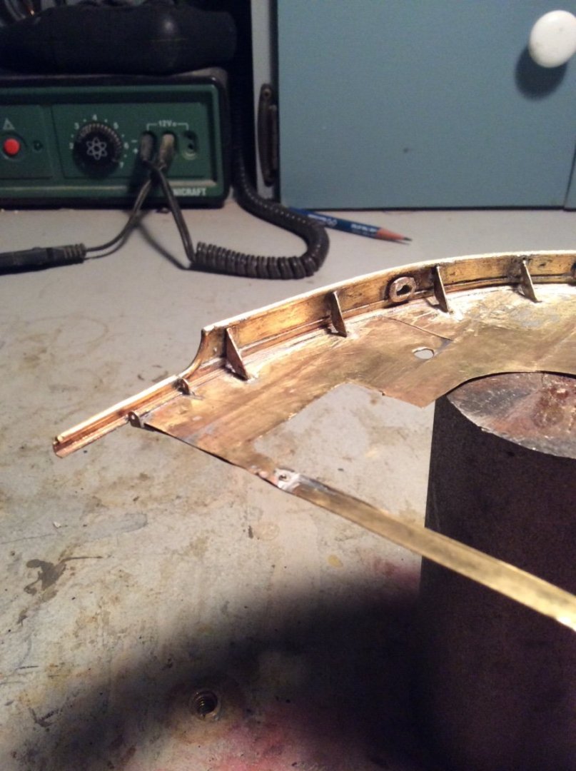
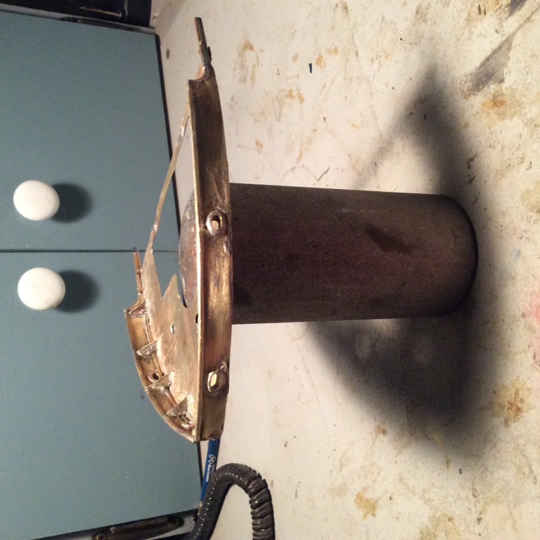
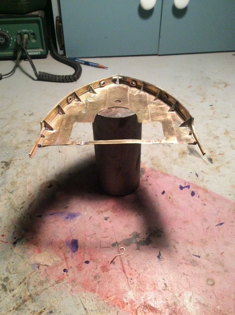
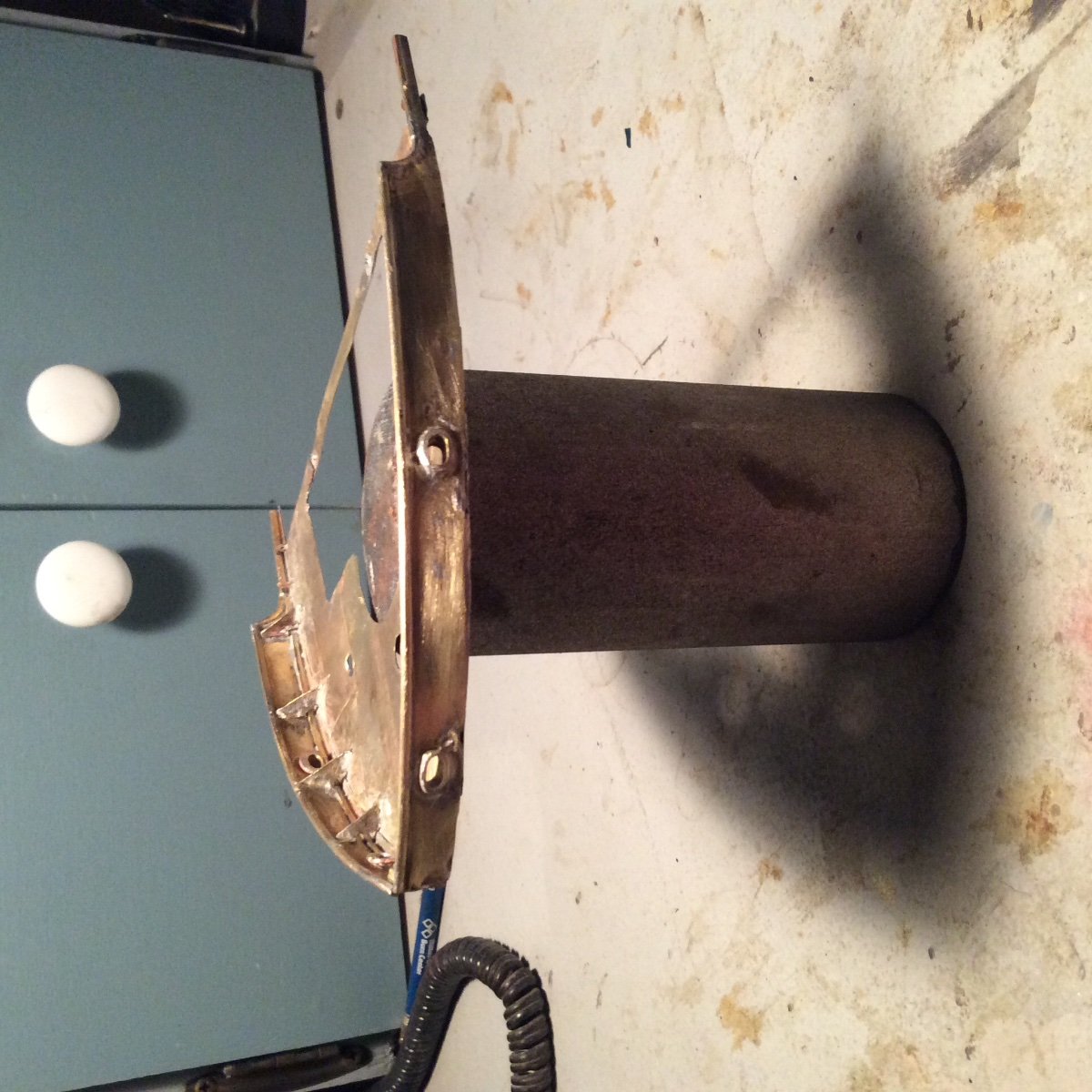
I reached another minor milestone over the past weekend. I finished the forecastle deck and bulwark assembly. This included adding since the last post, the bulwark supports, the mooring pipes, chain plates, and the round caps on the curved bulwark ends. All work is soldered brass.
The bulwark supports required a judgement call. They are clearly shown on several drawings for the main bulwarks, but not for either the poop deck or forecastle deck bulwarks. I did not include them for the poop deck but here there are other supporting structural elements. I included them on the forecastle deck for several reasons:
There are no other supporting elements for this deck, and the aft ends of the bulwarks are completely unsupported.
The forecastle deck is exposed, especially if the boat heads into the wind to ride out a storm.
I found several photos of Great Lakes vessels of the same era equipped with these braces.
Results posted in the photos below. Next, the forecastle deck bulkhead.
- mtaylor, Prowler901, FlyingFish and 10 others
-
13
-
Eric, just catching up on your interesting gunboat project although a little late to the game. I have found that brass sheet as thick as .010in can be easily cut with a pair of ordinary scissors. The cheap stamped sheet metal ones work particularly well.
Re: your Katy Railroad Christmas present book. If you look through your riverboat book stash I believe that you will find a set of drawings for a Mississippi River Railroad Car Ferry. It would make an interesting next project.
Roger


Mycenaean War Galley by Woodrat - 1:48 - Shell first Plank on Frame
in - Subjects built Up to and including 1500 AD
Posted
Steven, I’ll have to do some thinking about that. There are actually two different stability considerations. Initial stability (applicable to small angles of heel), and Range of stability ( the angle at which the righting moment disappears). We are concerned here with the former, as a slight heel will cause rowing to because difficult and the hull to flood.
Roger