


Roger Pellett
-
Posts
4,519 -
Joined
-
Last visited
Content Type
Profiles
Forums
Gallery
Events
Posts posted by Roger Pellett
-
-
Interesting project! Not specifically related to Florida waters but they supposedly said these old steamboats “could float on a heavy dew.”
Roger
- mtaylor, Harvey Golden and Canute
-
 3
3
-
Actually, in the 1960’s there was quite a bit of, for its time, high level Naval Architecture performed to optimize these towboats. Propeller/Kort nozzle combinations, flanking rudders, and even tow sizes were all studied.
The University of Michigan operates the second largest experimental Naval Architecture Towing tank in the USA. At 450+- feet long it is about half as long as the US Navy’s 1000’+ long tank. As a student in the early 1960’s I remember a model towboat with various numbers and arrangements of barges being towed. This would have been an expensive project and I don’t remember who the client was. It could have been US Govt Maritime Commission. Someone, however, spent a lot of money determining the optimal way to make up a tow.
Roger.
- Keith Black, bridgman, Cathead and 4 others
-
7
-
Your keel rabbit looks like it’s coming out nicely!
- Keith Black, FriedClams, mtaylor and 1 other
-
4
-
-
-
Valeriy, great work as usual.
I’m sure that you noticed the split accommodations for the crew; one before the stack and one behind it. This was typical of steamships built in British shipyards for the British Merchant Marine. The reason? The Deck Crew insisted on separate accommodations from the Engineers!
At the Beginning of World War II, the famous American Naval Architecture firm of Gibbs and Hill was contracted to modify the design of the the British Ocean class cargo ship design for American mass production, the result being the famous Liberty Ship. The Oceans featured deck crew quarters separate from the engineers. Gibbs and Hill eliminated this silly feature, combining everything into one deck structure.
Roger
-
Re; Window AC Unit
In 1972 I made my first of several business trips to Europe. To visit a nearby Mannesmann pipe forging plant I stayed in a hotel along side the Rhine River in Düsseldorf. I was fascinated by the variety of river craft passing by. These vessels of several European Nationalities were often crewed by families and had potted flowers at the windows, laundry drying, bicycles and occasionally a small car stored on board.
My point is that riverine craft are often an interesting mix of maritime culture and down home amenities. While the modern US towboats are usually corporate owned they do not hesitate to utilize shoreside gear.
Roger
- mbp521, mtaylor, Keith Black and 2 others
-
5
-
The first question that you need to answer is how you plan to build it. Lumber choices then follow.
The currently popular method Is POB. This consists of erecting many bulkheads on a wooden spine and planking hull with wood strips. You will almost surly need to apply copious amounts of sort of harden-able putty to help you fair the result. As GrandpaPhil suggests this sort of model can be sheathed with fiberglass. Wood for this type of construction: Central spine, bulkheads quality plywood, 3/8” thick. Basswood or pine strip wood planking.
The other option, less popular today is a carved wood hull. This system was used to build the large experimental models for tank towing to determine hull resistance and the magnificent large scale models of US Navy warships built by Gibbs & Cox during World War II. Their 1:48 scale USS Iowa on display at the Smithsonian is an example of model making at the highest level. You of course carve this type of hull from a solid log! Instead you laminate layers of wood band sawed to shapes derived from the waterlines found on the vessel’s lines drawing. Personally, I love carving ship model hulls. If I were doing this, I would use quality 1in nominal or perhaps 5 quarter lumberyard pine.
Roger
- GrandpaPhil and Canute
-
2
-
Building ship models can involve solving such a wide rage of problems that it really depends on what you’re trying to do.
For gluing wood to wood commonly available PVA glue; the yellow stuff. Elmer’s, Titebond, both work fine. Possibly other brands too. IMHO, it’s all the same stuff. Requires clamping pressure.
Special gluing problems like lightly loaded or interlocking metal to wood joints: Nitrocellulose based glue. Nitrocellulose based clear fingernail polish works great. It also works for wood-wood joints where clamping pressure cannot be applied. Duco is its the same stuff, just thicker.
For larger wood metal joints, Epoxy. I especially like JB Weld, it’s easy to squeeze out a couple of blobs and mix. Eyeball can judge 1:1 proportions.
CA Glues: Don’t use!!
Roger
-
US Navy Launches changed significantly during the period before the Civil War. Note that I refer to a specific boat type, not just any boat carried aboard a Warship. First of all they were sloop rigged. Ref; US Navy Ordinance Instructions 1860. Other details are listed in period seamanship manuals.
Roger
-
In the NROTC program Naval History was a 1 semester course, I believe sophomore year. Like OCS, Victory at Sea was part of the curriculum. Some guy, a fellow Midshipman was allowed to bring his stereo to class so we got full benefit of the music.
Roger
- allanyed, mtaylor, Chuck Seiler and 2 others
-
5
-
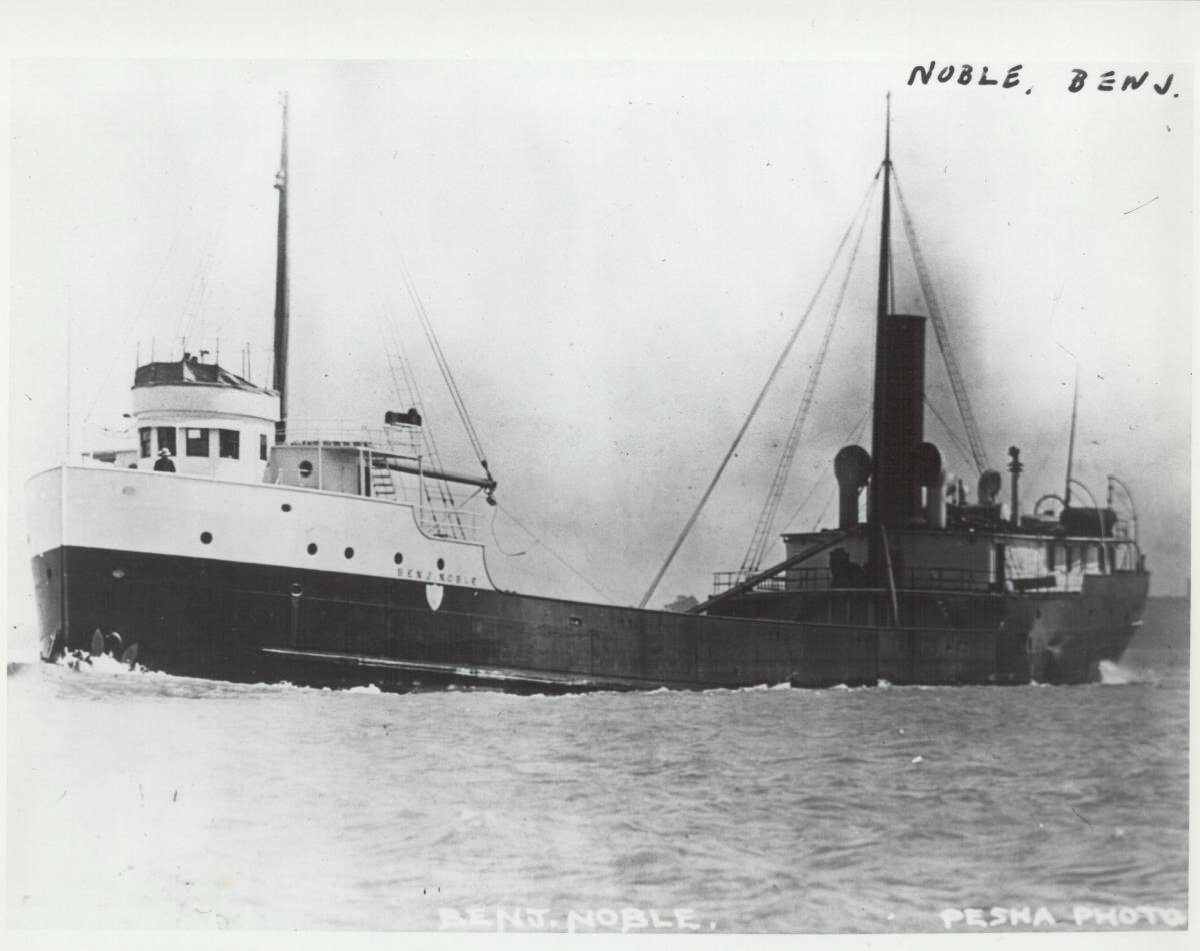
These double or raised Pilot house were seen on many Great Lakes vessels too. The original arrangement was an open bridge atop a closed pilot house. The watch stander stood on the open bridge and relayed orders via speaking tube to the wheelsman below. Later the open bridge was enclosed resulting in a second pilot house.
Photo original arrangement below:
Roger
- Canute, mtaylor, GrandpaPhil and 3 others
-
6
-
-
Sorry but I disagree. Properly heat treat steel tears. It does not chip like these blades did. Ordinary steel used for consumer products is relatively soft and ductile. It cannot be hardened by heating and cooling. To produce steel suitable for holding a sharp edge it must be alloyed with something else, the cheapest way being to increase the carbon content. This “tool steel” is hardened by heat treatment. After heating to a high temperature, it is rapidly cooled by quenching in water or oil. In this state it is very hard, brittle, and can shatter under impact. To make it usable it must be tempered at a low temperature. It would seem that in producing these blades the final step was omitted.
Long story short, they’re defective.
Roger
-
Steven,
I understand that materials readily available in one country may not be in another, BUT! Here in the USA we have a Company called K&S. They sell thin walled brass tubing in sized from 1/32” OD to about 9/16”OD. Each size telescopes into the next size larger. They also sell similar metric sizes. This stuff would be ideal for your roof supports. Using the telescoping of two sizes you could avoid soldering.
Roger
- Ras Ambrioso, Canute, Cathead and 2 others
-
5
-
Of all of the American Clippers being built or contemplated on MSW, Flying Fish appears to be in First Place. Maybe the reason is the availability of the Model Shipways Kit. Readers might, therefore, be interested that in the late 1970’s Model Shipways commissioned a new set of drawings to accompany the kit. The drawings were prepared by a then well known member of the Nautical Research Guild. It might have been Ben Langford but I don’t remember. Anyhow, at that time, he wrote a very interesting article in the Journal about the research that went into the new plans and the assumptions made. This article should be available as an inexpensive back issue from the guild office.
Roger
-
When I was 3 or 4 years old my father was building a 23ft L. Francis Herreshoff sloop in our side yard. This generated a lot of scrap lumber that he turned into a large bag of building blocks. I enjoyed them for years thereafter. No Legos.
Roger
- druxey, Keith Black, KeithAug and 4 others
-
7
-
I have little or no patience with computers but I have an active build Log for my current project here on MSW. Build logs here on MSW are stand alone. They do not require You Tube, Face Book, or anything else. In your case go to Build Logs for Kit Models. Pick the date range that applies to your model. Open a new topic, and start telling your story. If you have photos saved, click on Add Files at the bottom of your post. It’s really as easy as that!
Roger
-
You can make your own black paint with the exact amount of gloss that you want. Buy a tube of artist’s acrylic black and a bottle of acrylic gloss medium. A tube of white would also be useful for adding a “scale effect” to the black. Here in the US any craft store will stock these items. Start by squeezing out some black on a palette; a piece of glass is perfect. Mix in a little white to get the right scale color. Add a little gloss medium. When you’re happy with the result, mix up a larger batch, thin with water, and paint.
Roger
-
Some forum members, particularly those glazing the windows in the sterns of Nelson Era sailing ships use Mica. It supposedly cuts with scissors. Perhaps there’s some on your farm! Otherwise check Amazon.
Roger
- Canute, FriedClams, mtaylor and 3 others
-
6
-
Ok, I think that I can see what’s going on. It would appear that the red orthogonal lines on the floor are permanent, representing the waterlines and buttocks in the end (body plan) view of the hull. Vertical markers are then set on the floor at strategic locations at offset locations known from the lofting. The framing segments are set against these markers. The templates can then be used as a final check and for marking additional information as needed. A clever system.
Roger
- mtaylor, Keith Black and FriedClams
-
3
-
Andy, A remarkable project; duplicating in miniature at more or less the same time that the full sized vessel Is being rebuilt near by.
I have a question about the two photos that you posted. Old shipbuilding texts, both for wooden and iron/steel construction mention the use of a “shrieve board” for assembling frames. This was apparently a large portable floor with all frame shapes scribed on. Your guys appear to be using a similar but different system. I see the waterlines and buttock lines forming a grid (red lines) on the floor. I also see the plywood template. Are the actual frame shapes marked directly on the floor as with the shreive board? I can’t see from the photo. Was the template used to mark the shape on the floor or is it used somewhere else in the assembly process.
Roger
- FriedClams, mtaylor and Keith Black
-
3
-
For some, but by no means all kit manufacturers, the names given to these woods is little more than a marketing opportunity. Their advertising leads buyers to think that they are getting deluxe materials while in reality as Jaager points out the species offered would not be chosen by experienced scratch builders. As a general rule, the real premium ship building woods are slow growing species with tight, coded grain structure. Many fruit woods would qualify.
Roger
-
Great workmanship as usual Valeriy!
- FriedClams, Keith Black, Canute and 3 others
-
6
Where exactly is the waterline, or should it be?
in Painting, finishing and weathering products and techniques
Posted
Paul, From a Naval Architect’s perspective, you are exactly right. Determining the waterline at which a vessel will float requires knowing two things:
1. The weight of water displaced with the vessel assumed to be floating at several waterlines shown on the lines drawing. The results of this calculation can be plotted as a curve displacement vs waterline height.
2. The weight of the ship in different load conditions.
With this information, the draft of the vessel can be picked off for any load condition. In 1800 there were several methods for calculating displacement from the shape of the hull. These ranged from numerical approximations calculated manually, but based on techniques similar to the computer algorithms used today to actually measuring the quantity of water displayed by immersing a model in a tub of water.
The big unknown for ships built in the wooden ship era was the weight of the ship itself. Shipbuilding management systems were simply not capable of accurately predicting how much of the timber allocated for a particular ship would actually wind up in the finished vessel. Iron and steel construction would eventually change this.
The answer to all of this would come when the vessel was launched, and the draft of the floating vessel known. With this they could pick off the weight in the as launched condition from the curve. Adding the weight to be added to complete the ship, the armament, stores, etc. they could get a realistic estimate of the draft of the vessel in various loaded conditions.
My suggestion: Coppered vessels- Follow whatever drawings you are using. Vessels not coppered- White or back stuff up to the bottom of the Wales. The stuff was cheap.
Roger