


Roger Pellett
-
Posts
4,501 -
Joined
-
Last visited
Content Type
Profiles
Forums
Gallery
Events
Posts posted by Roger Pellett
-
-
-
Evan,
Yes, not very sexy, but if you open 5 compartments in a two compartment ship to the sea it eventually sinks! End of story. Although she was state of the art for 1913, she was not sailor (or more accurately owner) proof.
My current project, the Great Lakes Steamship Benjamin Noble is another example of where an owner, or in this case his representative’s, misuse of a relatively new well designed ship resulted in a tragedy. She was lost with all hands on Lake Superior overloaded with a heavy cargo that she was not designed to carry. This happened in April 1914, exactly one year from the loss of Titanic.
Roger
- Canute, bridgman and NavyShooter
-
 3
3
-
Start looking at scratch build logs in the 1900 and later category here on the forum. Pay particular attention to the research done to build the models. While no one is building the exact model that you are thinking of it will give you a good feel for the process.
Roger
- mtaylor, Jim Lad and challenger86
-
3
-
-
Keith,
The latest American Lake vessel launched 2-3 years ago has hatches that are three generations removed from the wooden covers fitted on the Benjamin Noble:
2nd generation- telescoping steel covers
3rd generation- One piece steel plate covers handled with a traveling hatch crane. (Used on all but 1 vessel in the American Lakes Fleet).
4th generation- one piece hydraulically operated cover (used on one vessel)
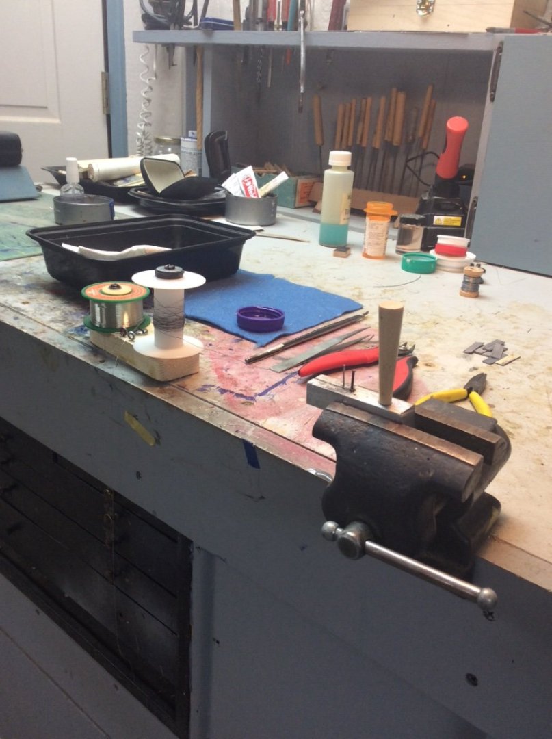
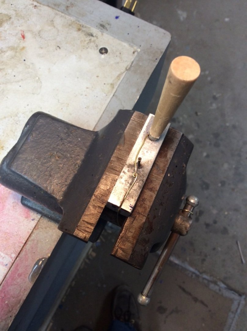
The tapered plug was just there to fix one end of the wire. The other end was attached to the closest spool shown in the first photo. This allowed me to put tension on the wire to endure round, uniform rings.
Roger
- mbp521, FriedClams, KeithAug and 6 others
-
9
-
Ringbolts-
Work over the last two months centered on completing the hatches. There were three stages to the job; the 148 ringbolts, completing the hatch boards, and making the hatch bars that prevented the wooden hatch boards from floating.
Each of the 72 main deck hatch boards and the 8 bunker hatch boards were fitted with two ring bolts. While these usually appear on any model with wooden hatches readers might be interested in how they were actually used. This is described in Jay McCormick’s 1942 prize winning book November Storm. The book is a fictional account of a young man’s season aboard a Great Lakes Freighter fitted with wooden hatches. Shortly after joining the vessel he is called upon with another deckhand to remove the hatch covers for unloading.
Each hatch board, weighing about 150# was handled by two men each armed with a short wooden “hatch bat”. One end was pushed into a ringbolt and the other held by the deckhand. Working in unison at diagonally opposite ends the 9ft long hatch board could be lifted and walked over to the side of the deck. Since time is money, this had to be done quickly, before the vessel was tied up at the loading or unloading dock. The effort required is hard to imagine!
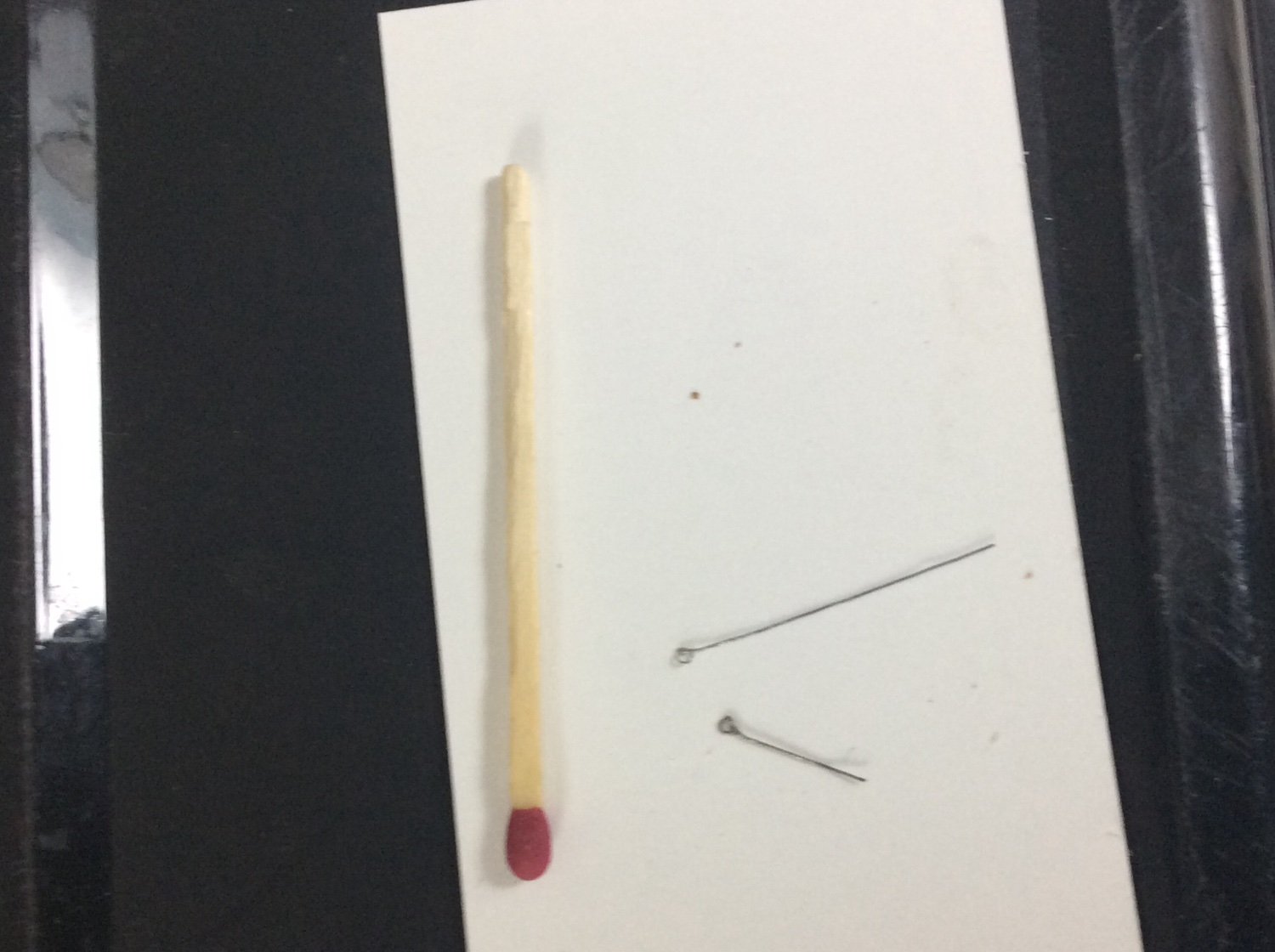
In my case, the problem was figuring how to make them. Each ringbolt ring had an OD of 6” so at 1:96 scale this would be 1/16”; Tiny! A feature of scratch building is the time that must be spent figuring how to make things, particularly if one chooses to build a variety of models and to work at different scales. As a result, several frustrating work sessions can go by until things get figured out. In my case, I first developed a system that I posted in the metalworking section of the forum that involved using a hand drill to twist a loop of wire. I abandoned this as it didn’t produce a round ring.
The system that I eventually used is shown in the photos below. It involved drawing .010” diameter wire around mandrel of 1/32” aluminum wire and soldering the loop with a drop of .010” diameter solder on the tip of a very small soldering iron. The result is slightly Under-scale but looks good relative to the hatch board. I began by using specially tinned brass wire but after running out found some .010” steel wire in my stash that was even easer to solder.
Roger
Note: the brass wire in the second photo is intentionally oversized to demonstrate the concept.

-
What you really need to start is either a lines drawing or table of offsets from which you can make your own lines drawing. This is not information that you would likely find in the hands of operators; Steamship companies, shipboard crews, etc.
Apparently Finland was built by W. Cramp &Sons, an American Yard near Philadelphia. So, who holds Cramp’s Archives? Maybe Philadelphia’ Franklin Institute? Just a guess.
Roger
-
There is usually a lot of old lathe parts on EBay. I know buying things on EBay can be chancy...But ?
Some parts such as nuts, bolts, bearings, etc. will be standard industrial stock items Fortunately the lathe is belt driven with speed regulated via stepped pulley so if necessary, the old motor can be easily swapped out for a new one. You can probably use the lathe without replacing some missing parts. These lathes regulate the travel of the cutting tool vs. the rotation of the spindle using a series of changeable gears. This is necessary for cutting threads, but if the gears are missing the lathe can still run.
You should also inventory the lathe’s accessories that you have; chucks, tool posts, etc. Rule of thumb is that the cost of these will often exceed the cost of the lathe itself. If you buy a new machine like a Sherline, it will have to be outfitted with new accessories as the old ones will not fit.
With the notable exceptions of the Unimat and the various specialized watchmakers lathes the smaller model makers lathes are (by my timeline) a relatively new item. Back in the 70’s and 80’s there were lots of books and articles dedicated to using these and similar full sized machines for model making. I suspect that your lathe has good bones and it’s worth investing some money to restore it.
Roger
-
If you have the Atlas Craftsman lathe, you have a tool that I have llusted over for years but never owned. The top of the line lathe for modelmakers would be a Sherline but outfitted with chucks and other accessories to be useful will probably spend $1500++ and you will lose some capabilities; power feed and a good system for turning tapers.
Roger
-
Our craft (to me it’s not just a hobby) is so broad that the the tools required are largely dependent on the ship that you have decided to model. The most often used tool in my workshop is my drill press. While I seldom use it for the model itself, I often use it to fabricate Theo jigs and fixtures necessary to fabricate the parts for the model.
-
A shameless plug for the (very) inexpensive thin rip guide sold by MSW’s owner the Nautical Research Guild. Using this, the wood being cut is not squeezed between the fence and the blade. This should produce more even cuts.
Since you haven’t used the Saw for a while, have you checked the fence alignment. There are instructions for doing this here on the forum.
Adding to Mark’s comment #2 above, a handy Saw accessory is a simple block of wood that can be used to press the piece being cut against the fence. Using this, the right hand pushes with the push stick while the left with the wooden block presses the wood being cut against the fence. The NRG’s guile eliminates the need for this.
Roger
-
Small disc sanders range from the single (high) speed models to the variable speed state of the art models made by Byrnes Model Machines with many in between at all price points. All are highly useful.
I assume that the belt sander that you mention is a stationary one, not a hand held model. In my opinion belt sanders are way to aggressive for fine work and have little direct application to model making.
I have both disc sanders and a stationary belt sander. I use the disc sanders all the time. The belt sander is only used to grind and sharpen cutting tools for my metal lathe.
Roger
-
Melissa,
First, congratulations on the museum display of your Philadelphia model. Can you tell us where it is located?
Air Brush. IMHO it depends what you want to do. This ranges from spraying paint to engaging in shading and weathering, etc. I personally am happy if I can just lay down a nice coat of paint and am on my second Badger 350. Advantages; inexpensive, robust, easy to clean, user friendly. Disadvantage, pretty much on/off with nothing in between.
As important is your air source. I have a compressor/ air tank combination available at any bid box home improvement store; on sale cost about $100. It’s noisy but provides plenty of air. These units generate air at 125psi but have an integral regulator to dial outlet pressure down to airbrush pressure. This is necessary. Don’t ask me how I know!
Roger
-
-
-
Since you may not be familiar with my reference to Harold Hahn allow me to elaborate some.
Harold Hahn was a prominent model maker back in the ‘70s and ‘80s. He developed a system for mass producing the two ply blanks for the frames for POF models. His work did much to encourage others, including me, to dabble in building POF models. The resulting models resemble the old Admiralty dockyard models but the framing is not the same, nor does it represent full size construction practice. As a result his work has fallen into some disfavor.
His system, would however, be great for making fully planked Plank on Bulkhead models. You should be able to find details here in the forum via the search function. Volume 1 of the NRG’ Shop Notes available from their store also includes a full description of his system.
Roger
-
-
My present project requires a lot of holes drilled in brass and I recently needed to restock my supply of smaller sized wire sized drill bits. After reading previous posts here about jeweler/ watchmaking tools applicable to our craft I decided to investigate spade bits. Google search only resulted in umpteen offers for spade bits in fractional sizes (1/4” and larger) intended for rough carpentry work.
I checked a watchmaking tool source (I believe Otto Freil) and only found something called a Pivot Drill Bit that looked like it might be useful. This looks like a piece of pointed wire with two sides filed flat. I might experiment with one of these in the future. It appears that the watchmaking trade may have been invaded by Carbide too.😠
-
If you have a table saw you could make your own plywood that would be more suitable than anything that you could buy including the high priced stuff. Cut strips from ordinary lumberyard construction grade pine and laminate them with PVA glue. Two plies with grain oriented differently and joints staggered Harold Hahn style should work.
Roger
- woodartist, mtaylor, Canute and 3 others
-
6
-
I have a 4” Jarmac sander too and have encountered the same problems mentioned above plus both the “cross cut guide” and the sanding table are flimsy and require constant adjustment, but it works and I use it. The Jarmac tools (there were Jarmac mini table saws too) were standard equipment in model shops in the 1970’s when large engineering firms made models of industrial installations. These 3-D models made from project drawings were effective at checking for interferences between piping, equipment, and building structure. 3-D CAD modeling eliminated the need for these physical models.
There was nothing wrong with the Jarmac tools in their day. Rather, the new tools are an indication of how things can improve overtime if someone has a goal to offer an improved product.
Roger
- bridgman, Ryland Craze, mtaylor and 1 other
-
4
-
Brass Work Hardens. This means that when deformed at room temperature it gets harder. This can happen when the drill fails to bite And just sort of massages the surface that you are trying to drill. So, trying to drill with a dull drill can make it even harder to drill later with a sharp drill. You might try annealing the piece with the partially drilled hole to see if it makes a difference; heat to dull red and quench in water.
Are you clamping the piece that you are drilling in a vise? You should be applying a reasonable amount of pressure to get the drill to bite and it’s much easier to do this if the work piece is immobilized.
I have had zero luck with the 1/8in. shank plastic collar carbide bitts. Just looking at seems to cause them to shatter.
I am not familiar with ceramic bitts.
Roger
-
Steven,
Great job! 1100’s to 1400’s is a long time by modern standards but perhaps not so long for the ancients; particularly conservative mariners. Anyhow, you can really see how this vessel from the 1100’s could have evolved into the Carrack of the 1400’s. Every time that I look at your model with the braces to the stem the characteristic diagonal planking of the bows of the Carricks makes sense.
Roger
- mtaylor, Ferrus Manus, Glen McGuire and 1 other
-
4
-
I know that this is picky but correct terminology can sometimes help to understand what one is looking at.
The photo in post #157 above does not show “Rivet Heads.” These are the “points” of the rivets (the end of the rivet without the head) that have been “closed” hammered while hot to fill the slightly tapered hole in the shell plating. The actual trapezoidal shaped rivet head is on the inside of the shell plating.
Roger
- druxey, Keith Black, James G and 5 others
-
8
-
Great to see you back in the workshop again Keith.
Roger
- mbp521, FriedClams, Keith Black and 5 others
-
7
-
 1
1


The San Marco mosaic ship c. 1150 by Louie da fly - 1:75
in - Subjects built Up to and including 1500 AD
Posted · Edited by Roger Pellett
Unfortunately Naval Architects and Nautical Archeologists seem to be two different breeds “and never the twain shall meet.” All floating objects regardless of when built most obey the same laws of Newtonian Physics. In the end even these ancient vessels can be evaluated using basic Naval Architectural concepts. There is seemingly no reason why ancient seafarers would sacrifice freeboard by intentionally building a vessel with a crenelated hull.
Roger