G.L.
-
Posts
1,553 -
Joined
-
Last visited
Content Type
Profiles
Forums
Gallery
Events
Everything posted by G.L.
-

HMS ROYAL KATHERINE 1664 by Doris - 1/55 - CARD
G.L. replied to DORIS's topic in - Build logs for subjects built 1501 - 1750
Is that a paper gun? Amazing, it looks like bronze one!- 1,035 replies
-
- 6
-

-
- royal katherine
- ship of the line
- (and 1 more)
-
Patrick, Nice job. I like the color of your deck. What did you use to stain the planks?
- 756 replies
-
- 2
-
-
- galleon
- golden hind
- (and 2 more)
-
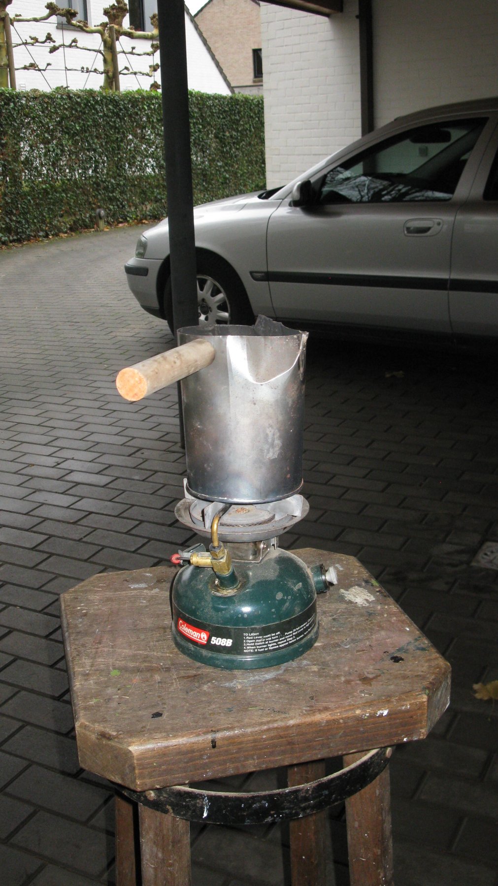
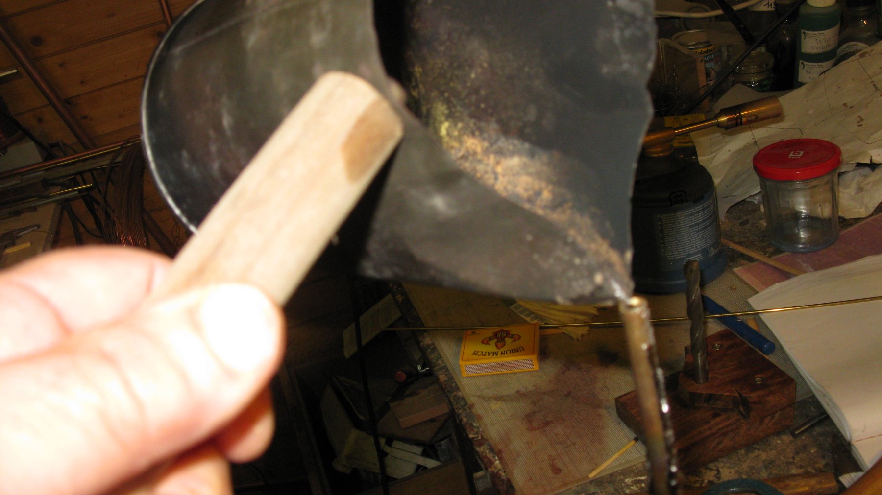
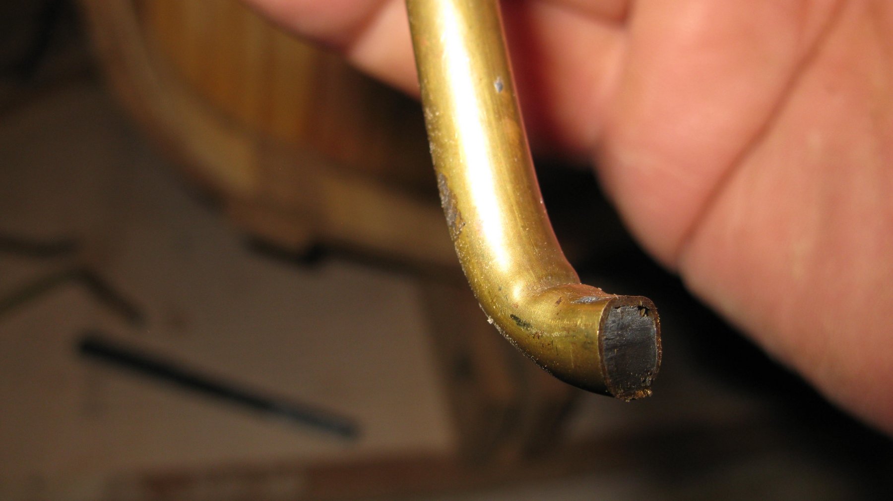
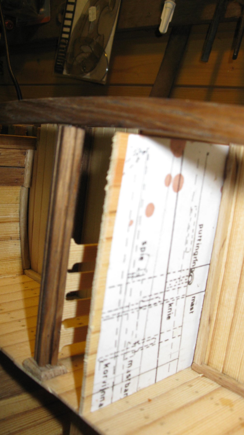
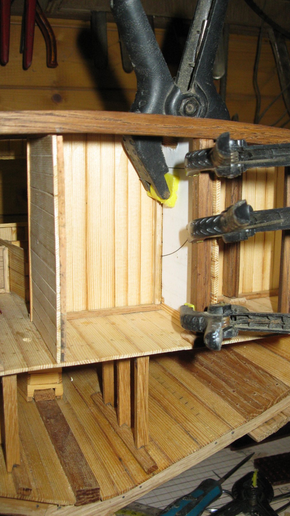
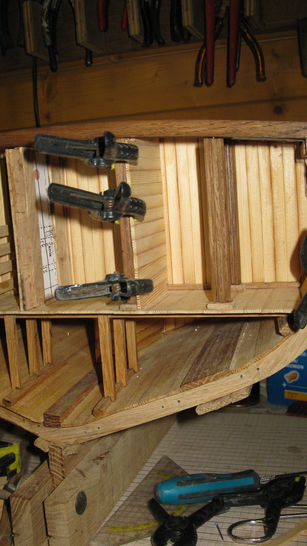
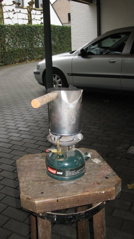
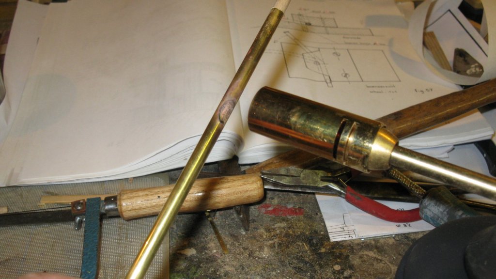
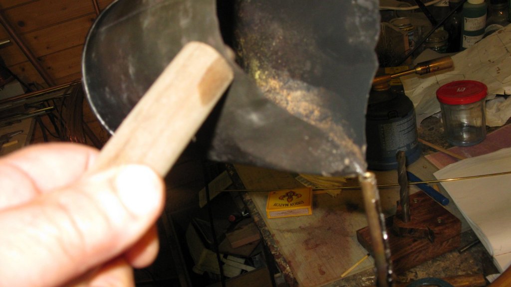
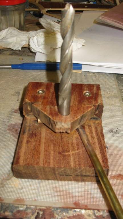
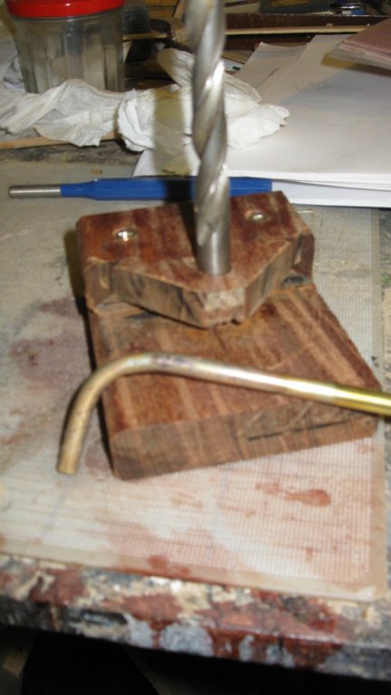
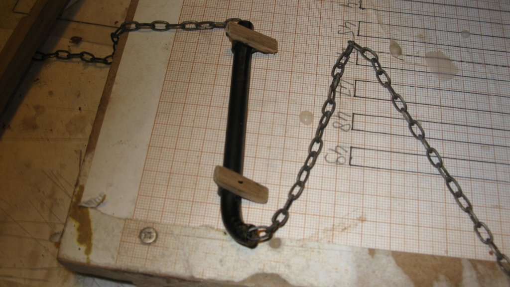
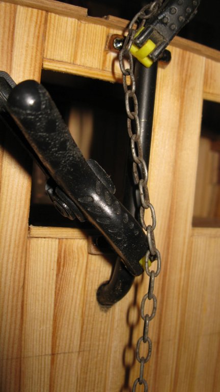
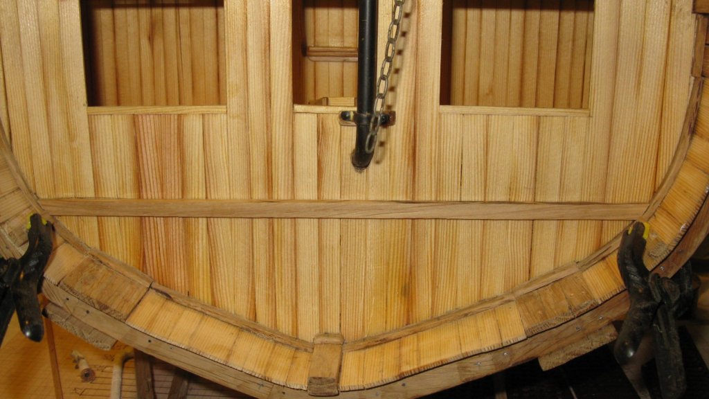
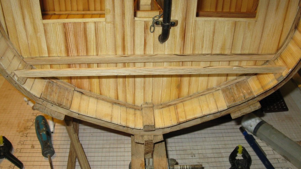
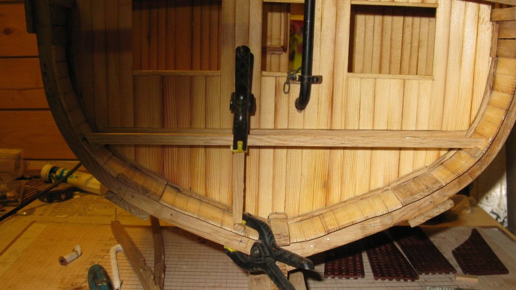
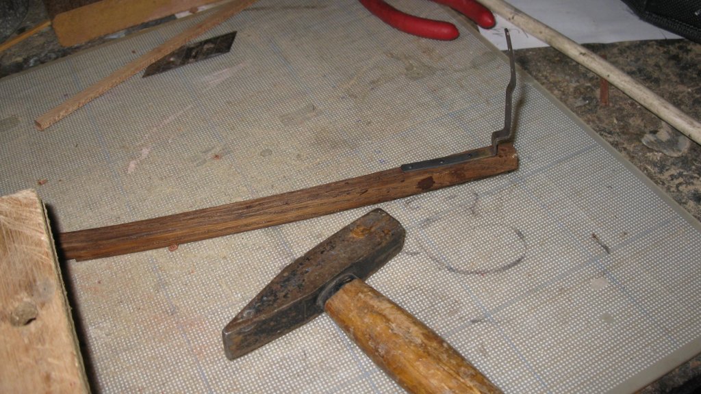
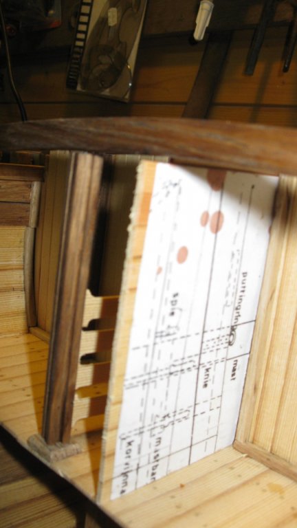
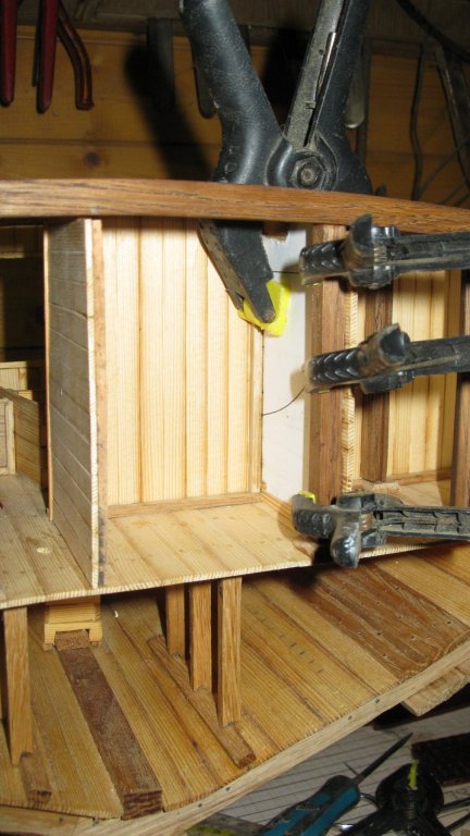
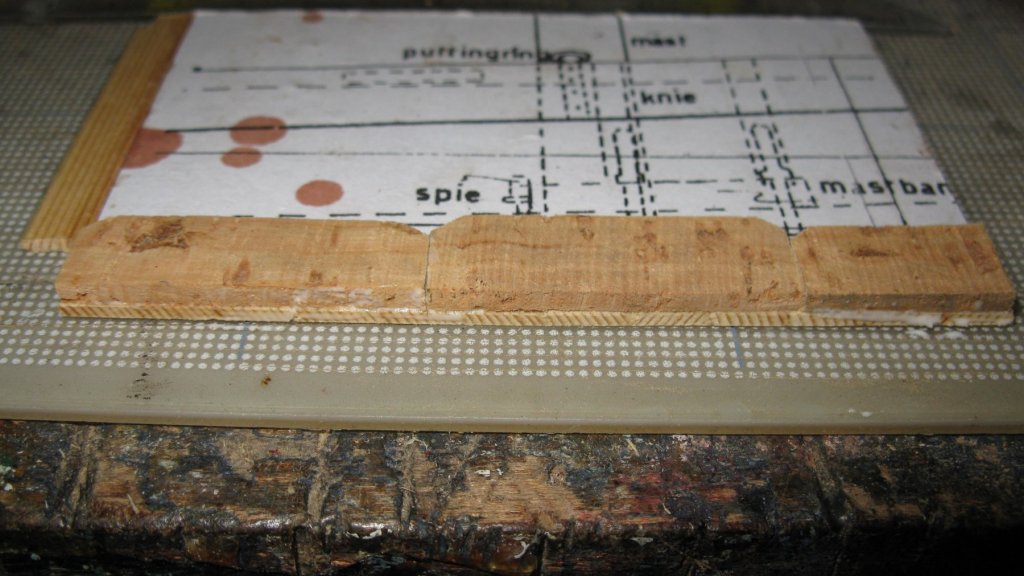
Thanks Carl, Pat, Michael and Yves. Here is the progress of last week: Part 15: The forward compartments. The area in front of the equipment store (circled part of the plan) consists of a spare nets repository (starboard) and a small warp hauling line store (portside), separated from each other by a central passageway in which is the anchor chain pipe. Those compartments are cut through in my cross section (dotted line on the plan). I start with making the anchor chain pipe. The pipe has a 90° turn to lead trough the bulwark to the chain box. A design of a folding bench is given in the practicum. The pipe has to be filled with fine sand to prevent it from nodding. The pipe must be heated and folded. However my problem is that the practicum is explaining to make a cross section on scale 1/30 and I are making mine on scale 1/20. My pipe has a diameter of 7.5 mm and not the 5 mm for the 1/30 scale. Whatever I try and however careful I am, my pipe is cracking instead of bending. I consult a modeler colleague who advises me to fill the pipe with melted lead instead of sand. So I heat the pipe to make the brass soft, melt some lead in improvised melting pot of a tin can and fill the pipe. I make now a new attempt to bend the pipe. I have now a 90° curve in my pipe. It is far from perfect and the curve is a bit wider than I would like, but I will do with it. I will melt the lead out of it and finish the pipe. The pipe, painted and provided with two mounting brackets and the anchor chain. Attaching the pipe into position. Preparing to lay the lower deck. The deck is laid. Placing the profile slats for the bulwarks. Placing the bulwark of the spare net store. Placing the bulwark of the small warp hauling line store. The forward compartments.


- 219 replies
-
- 14
-
-
- smack
- cross-section
- (and 2 more)
-
Valeriy, Thank you very much for the explanation but it remains still a bit of alchemy for me. I will have to deepen your pictures and recipe above with some colleagues modeling friends who have more knowledge about metallurgy than me.
-
What a beautiful ship! At scale 1/36 it will be a large model, I like that. I am subscribing to your log.
-
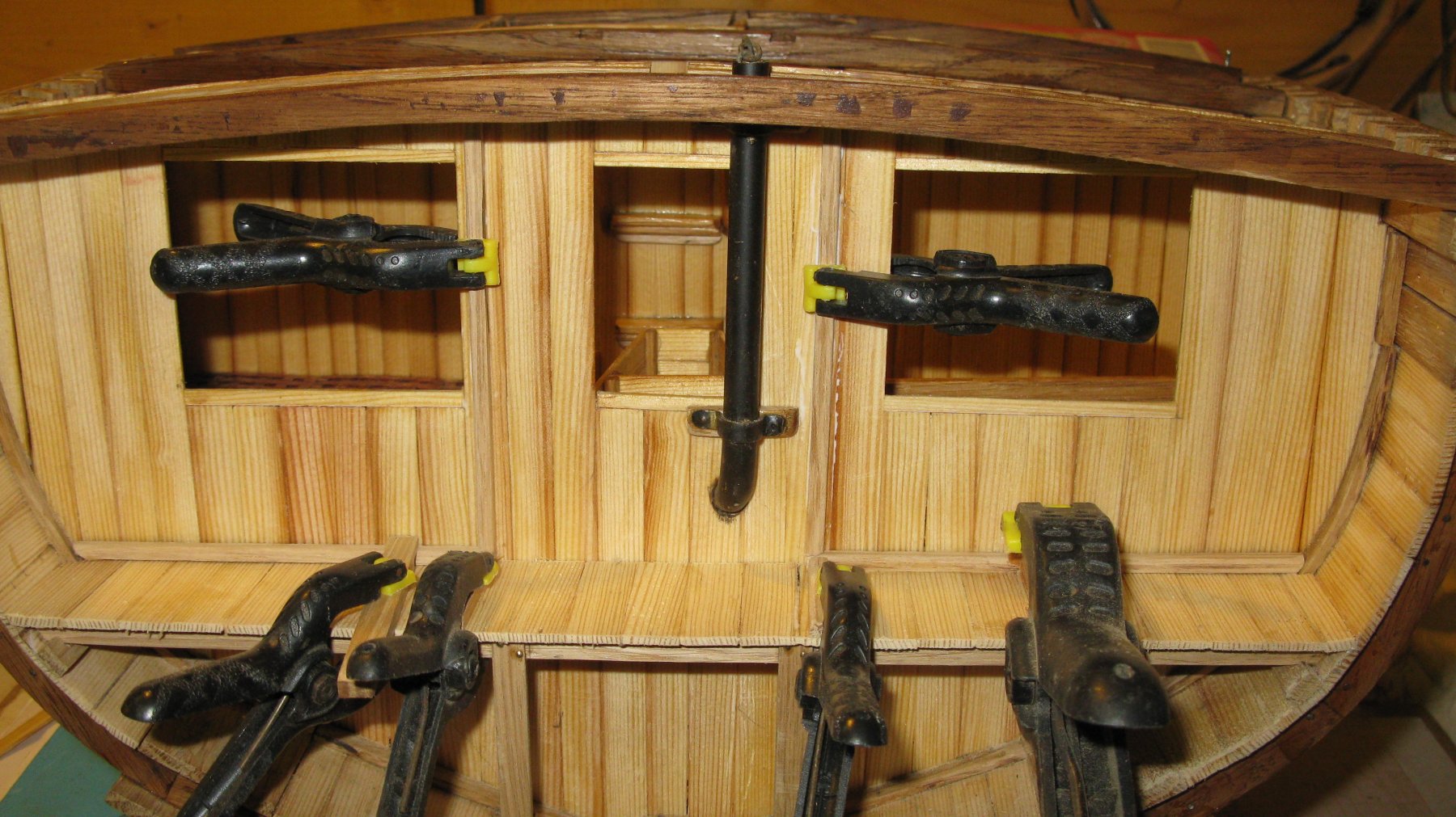
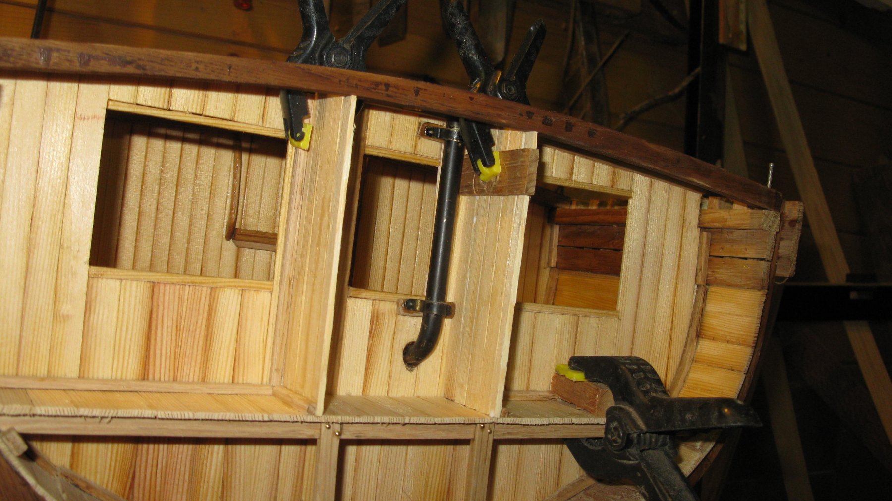
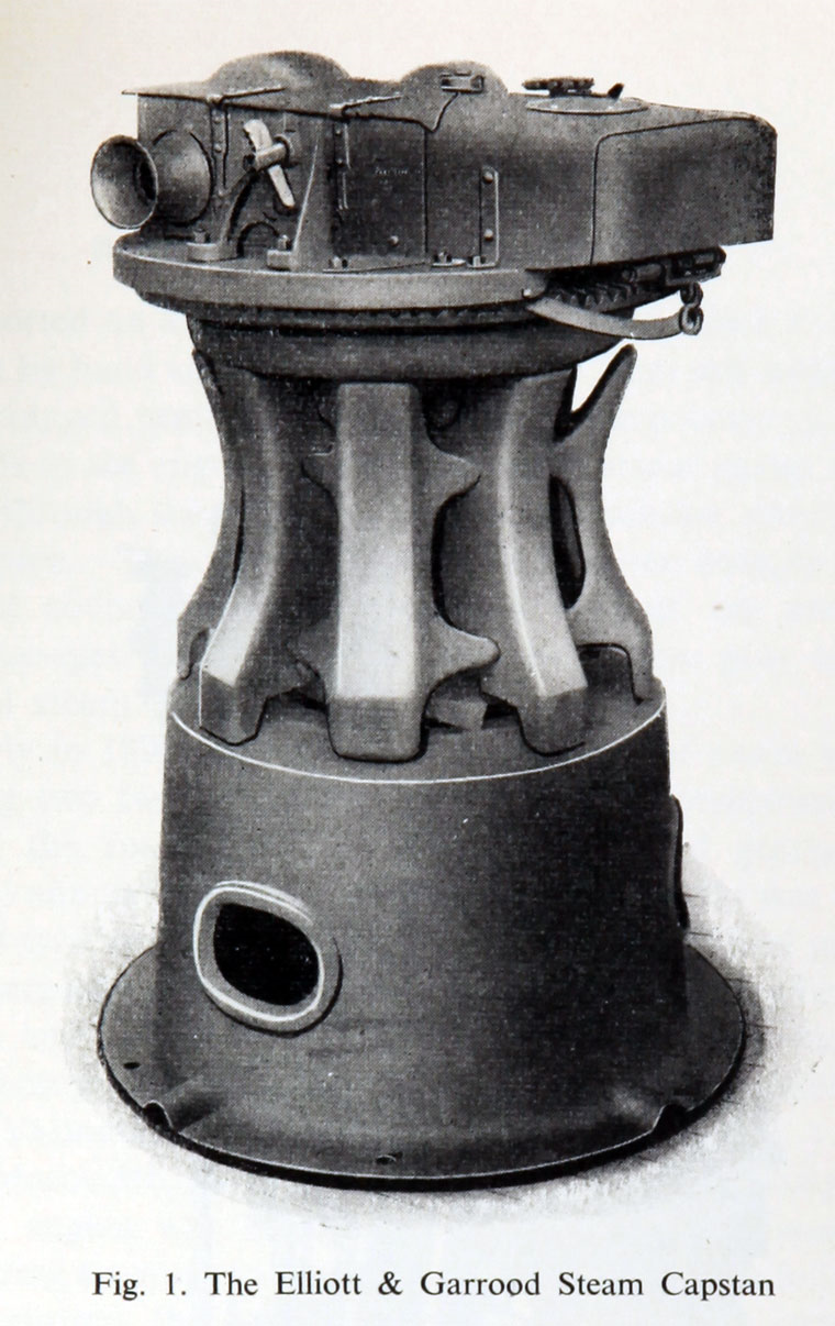
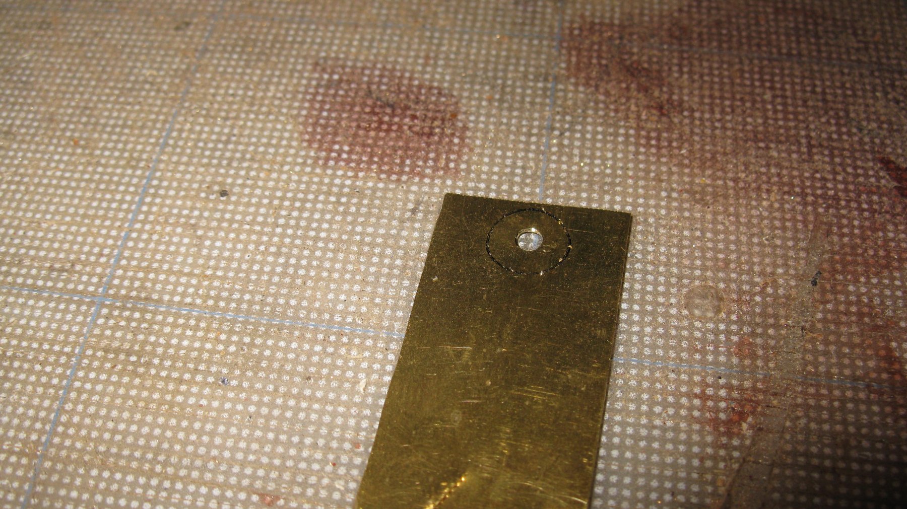
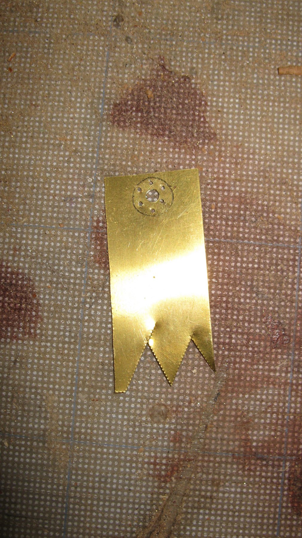
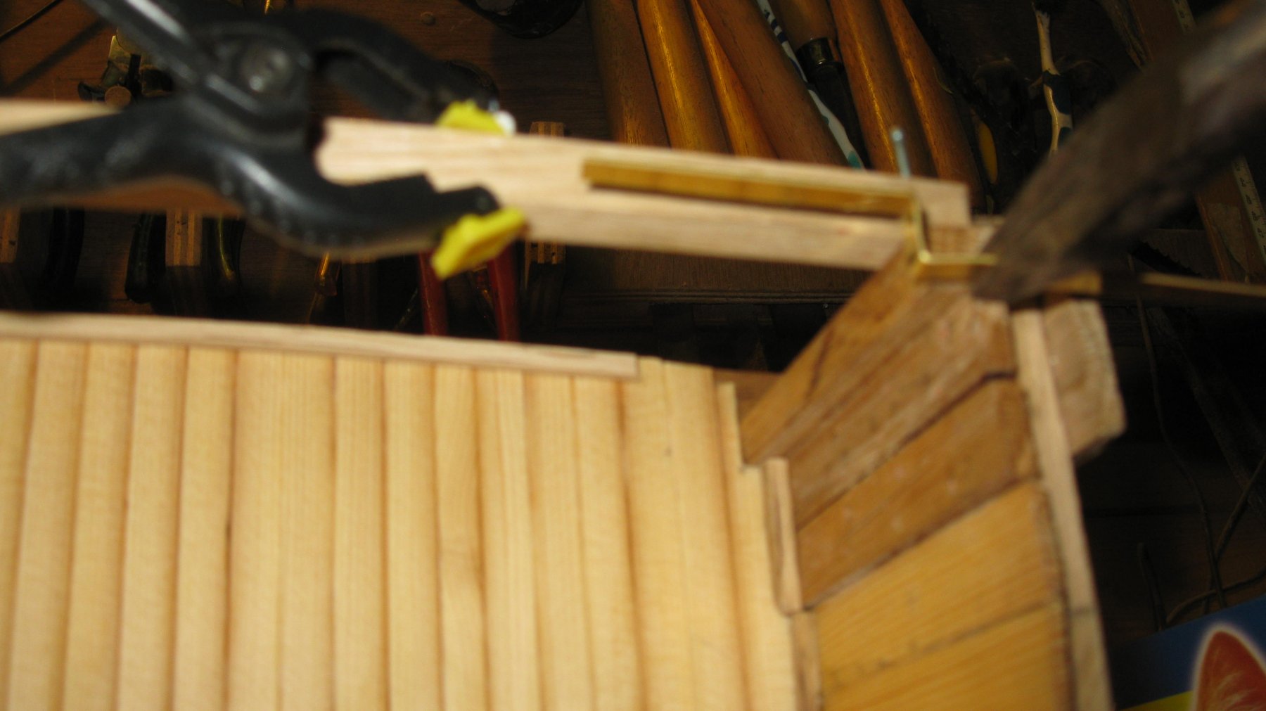
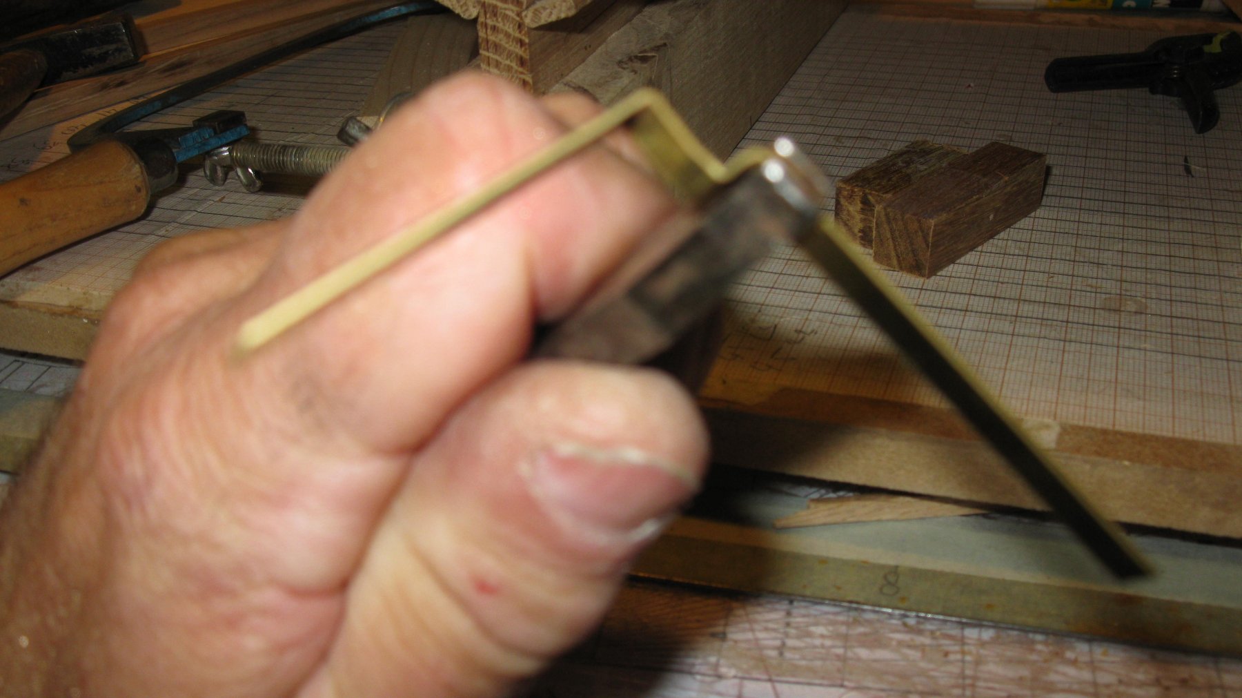
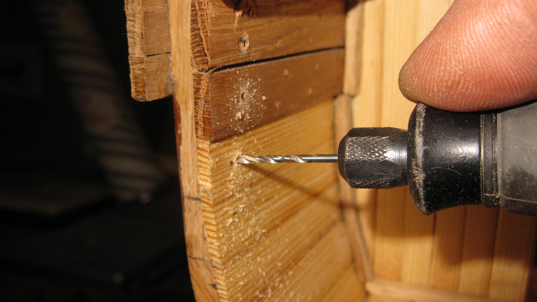
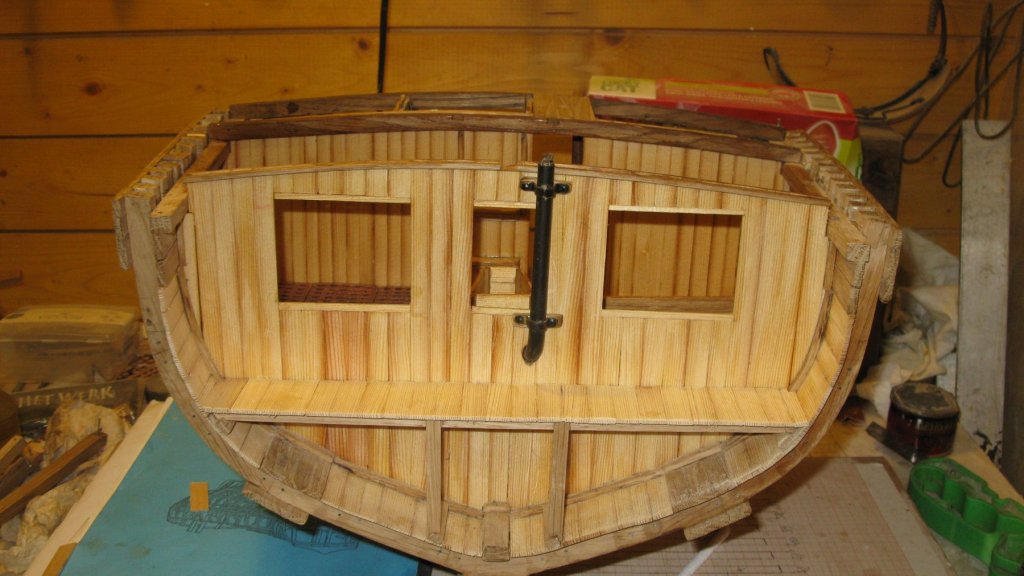
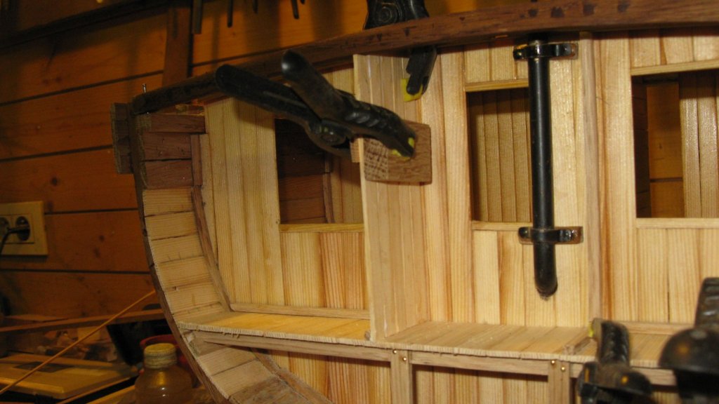
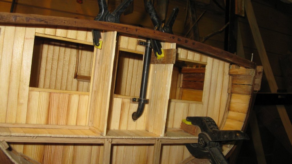
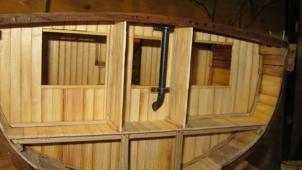
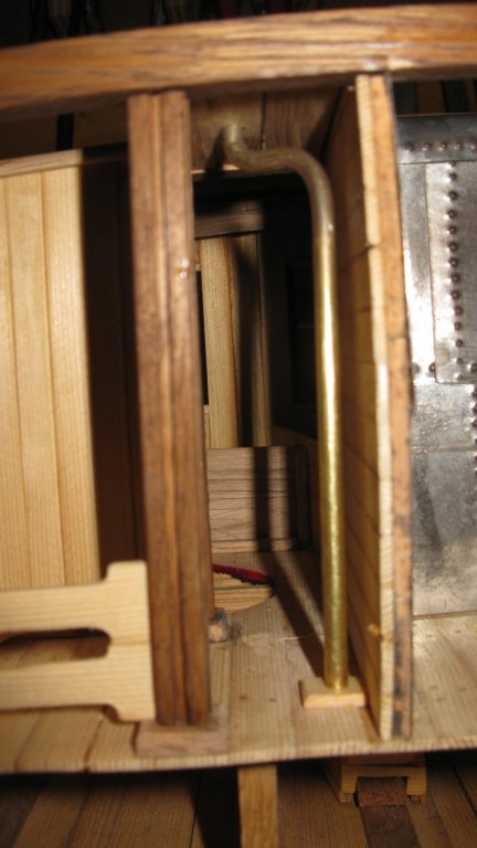
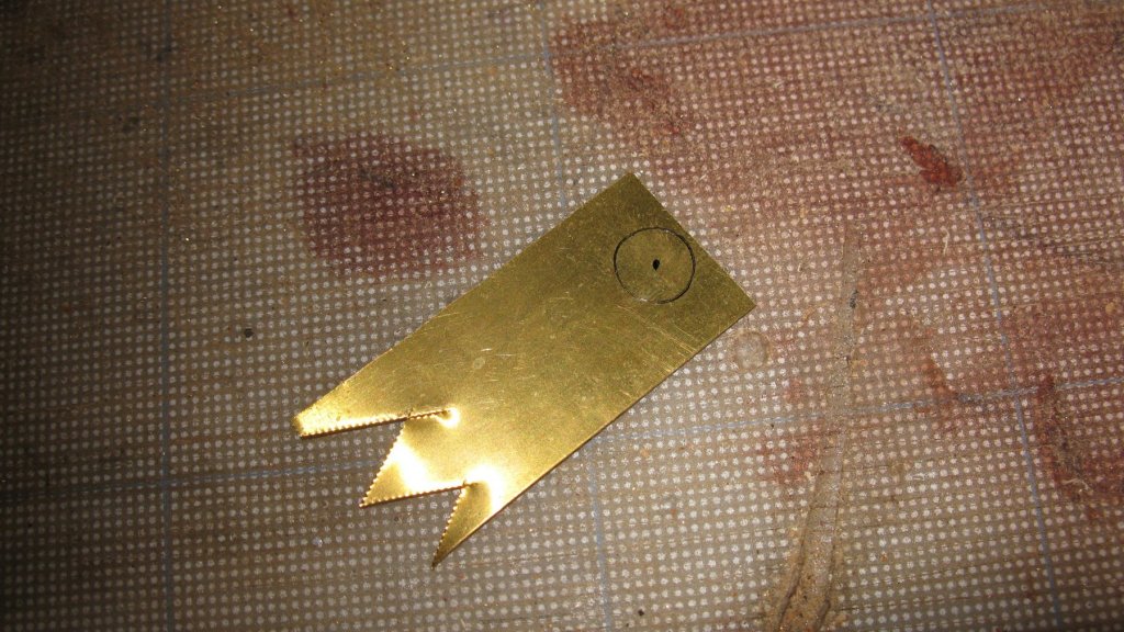
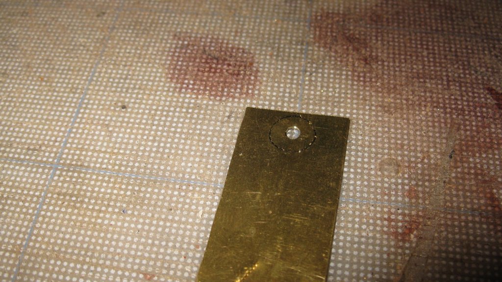
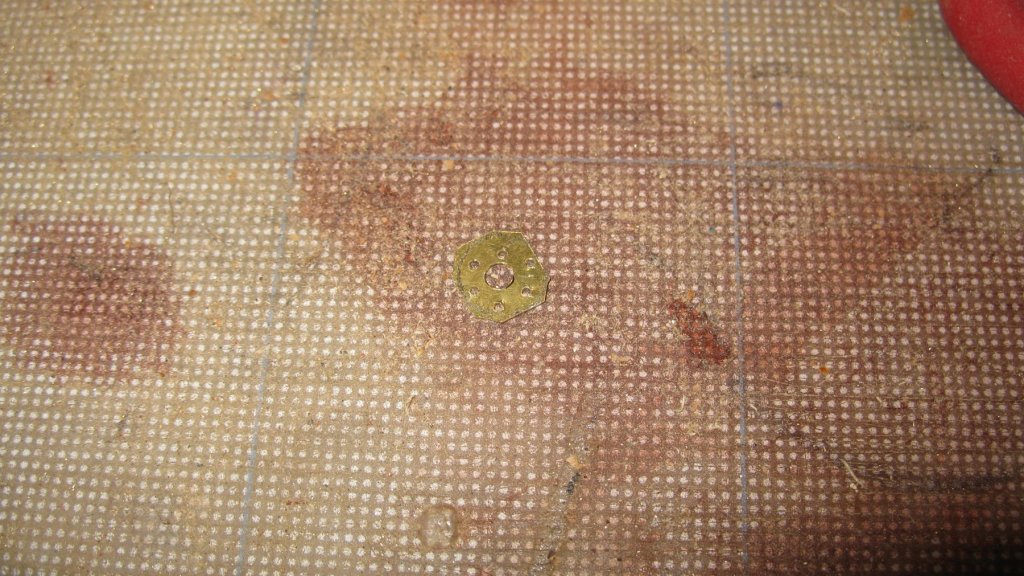
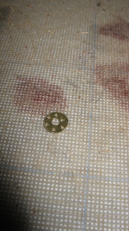
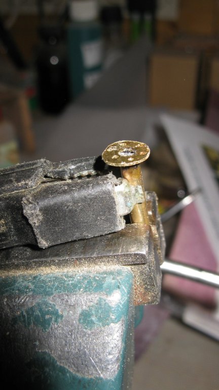
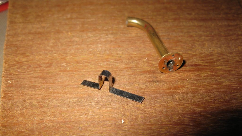
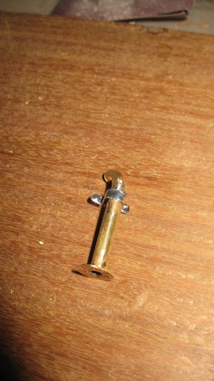
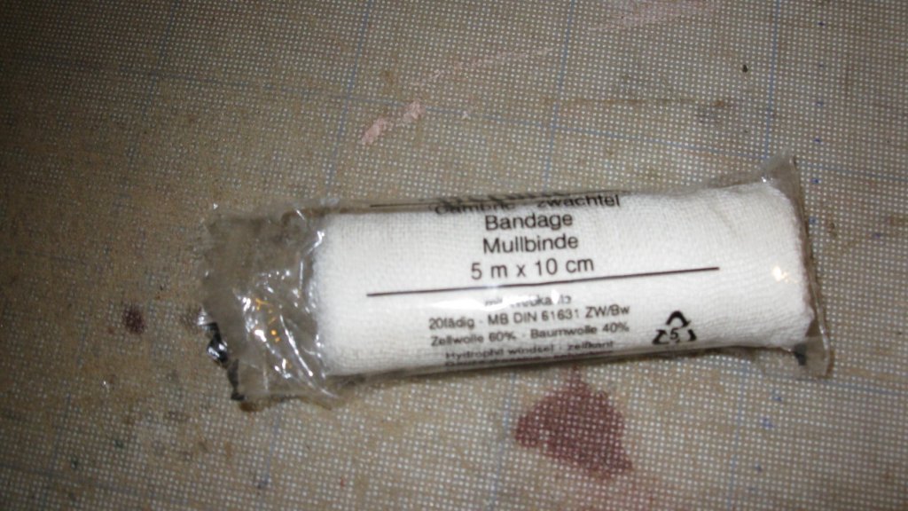
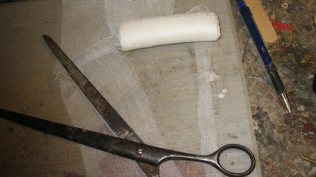
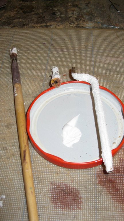
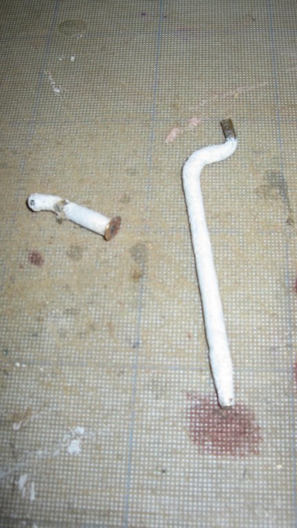
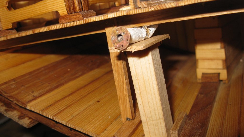
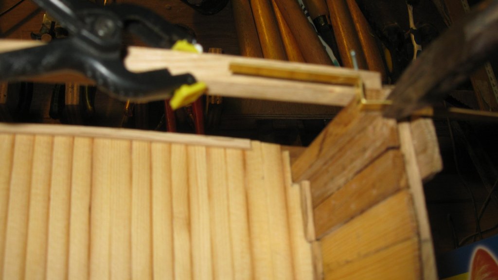
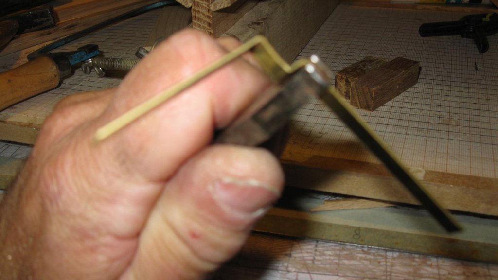
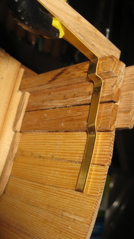
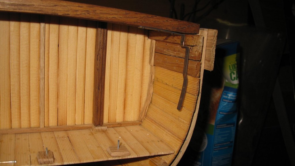
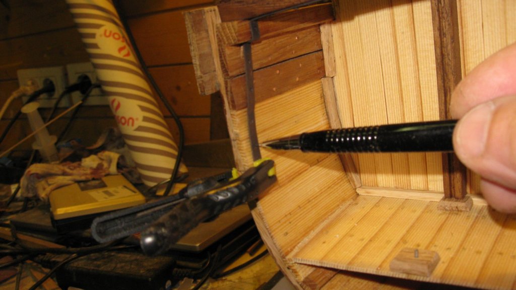
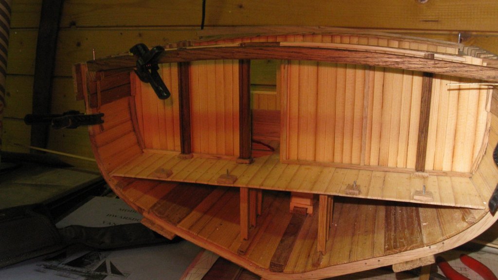
Smacks were often equipped with a steam capstan. In the 19th century the capstan was driven by a donkey steam engine which was connected to a gearbox below the capstan with a connecting rod. Later a more effective capstan was developed: the Elliott & Garrod's steam capstan. The steam under pressure could be led immediately from the steam pressure boiler to a gearbox on top of the capstan. This effected less loss of power than with connecting rods. The steam pressure boiler is situated outside the cross section, so I don't have to make it. On the other hand, the capstan has to be made, but that is a job for later. On the picture a Elliot & Garrod's steam capstan of a later generation than that on my smack. I start with lying the carlings on which will stand the capstan. I drill a hole in the middle carling. Through that hole will lead the steam pipe to the capstan. I curve a 4 mm brass tube which will lead from the upper deck to the lower deck. Below the lower deck the steam pipe goes further horizontally to the engine room more aft. My steam pipe will be cut off at the edge of the cross section. I want to end the pipe with a flange. Making the flange: drawing the outline on a piece of brass. Making a hole in it Making the boltholes Sawing it out Filing of the outline Soldering the flange on the pipe. Making a mounting bracket. The steam pipe is leading along quite a long distance, including more than two meters through the ice cooled fish hold. I can imagine that there will be a significant loss of temperature of the steam. There is nothing told in the practicum about insulation of the steam pipe. During the twenties of last century the health risks of using asbestos were not yet known, so I suppose that the pipe was insulated with a layer of asbestos. I will do it as well on my model. I will of course not use real asbestos but I will try to make a look alike. To do so, I take a roll of gauze bandage. I cut some narrow bars of it. I wind them around the tube and moisten them with textile glue. Then I paint them with white acrylic paint. The pipes into their places. The pipe below deck still needs a support for a while until the glue is dry.


- 219 replies
-
- 15
-
-
- smack
- cross-section
- (and 2 more)
-
Berto, Welcome on board of this log. The Modelshipwold forum is the place to be when you are interested in maritime history. Don't praise my craftmanship too much, you will see in other members logs that on this forum real artists are at work. I wish you much pleasure in following the build of my cross section.
- 219 replies
-
- 1
-
-
- smack
- cross-section
- (and 2 more)
-
Tony, Your planking looks to me very good. This will become an excellent model.
- 124 replies
-
- 3
-
-
- longboat
- Chaloupe Armee En Guerre
- (and 1 more)
-
I am looking very much forward to the progress of the Varyag to see how electroforming is working.
-
HMS ROYAL KATHERINE 1664 by Doris - 1/55 - CARD
G.L. replied to DORIS's topic in - Build logs for subjects built 1501 - 1750
I do not either because the bottle is still full.- 1,035 replies
-
- 7
-
-
- royal katherine
- ship of the line
- (and 1 more)
-
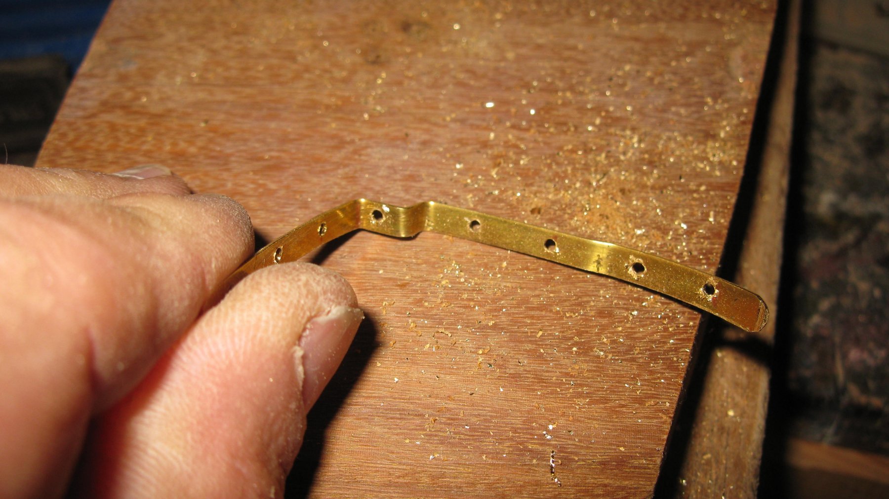
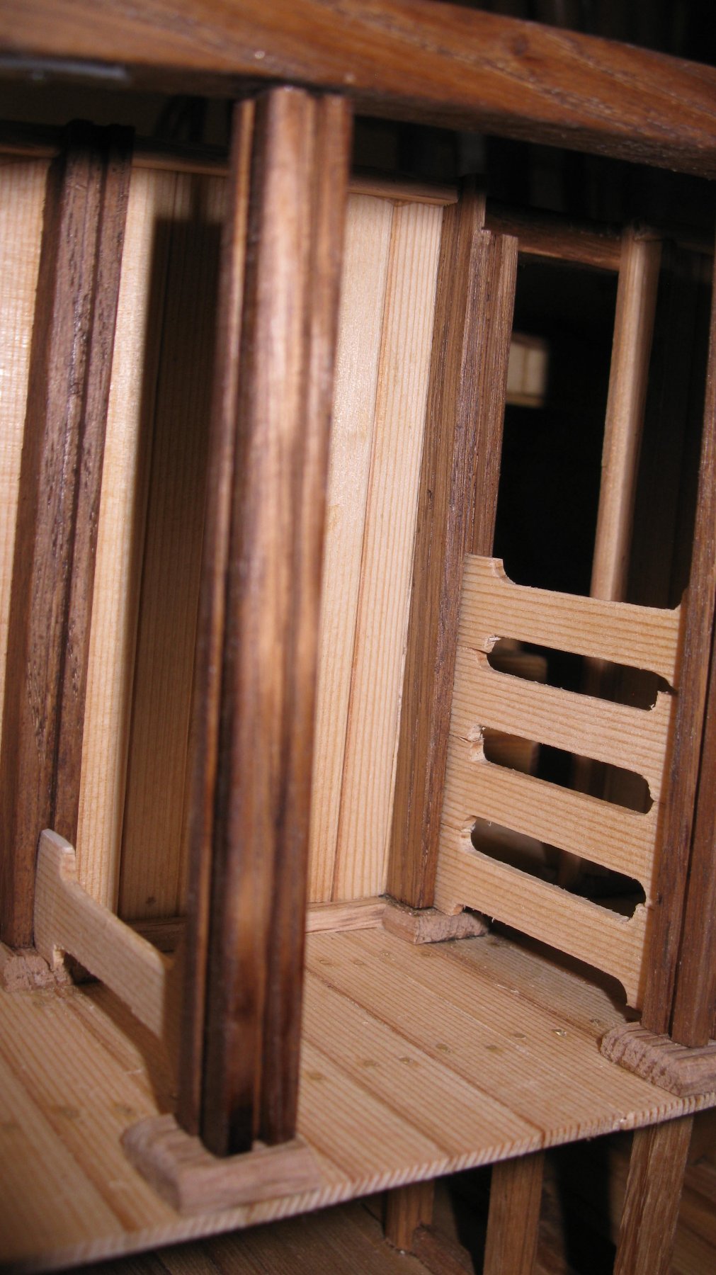
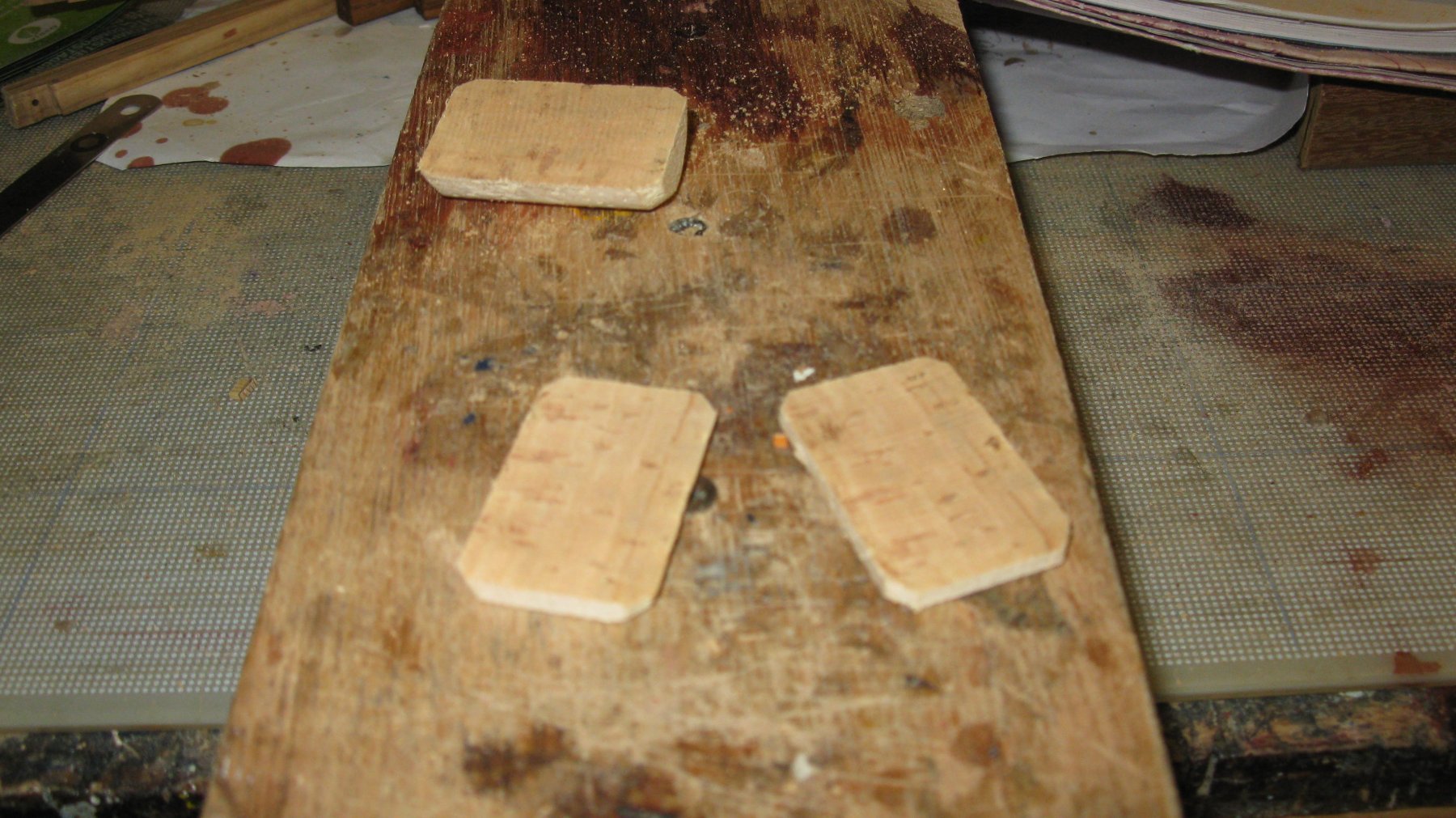
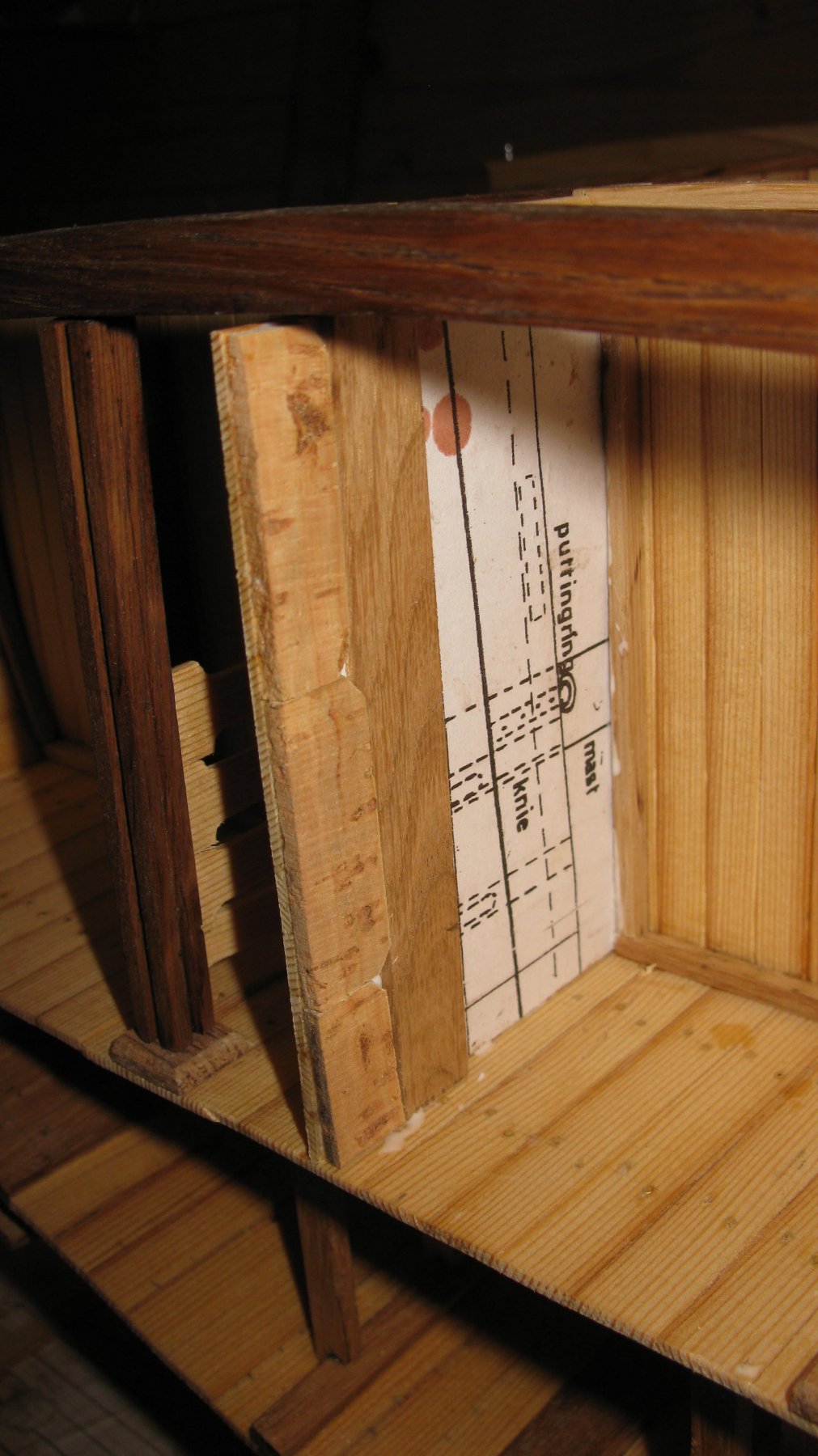
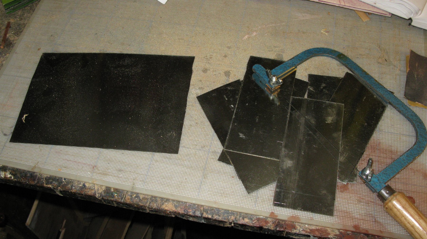
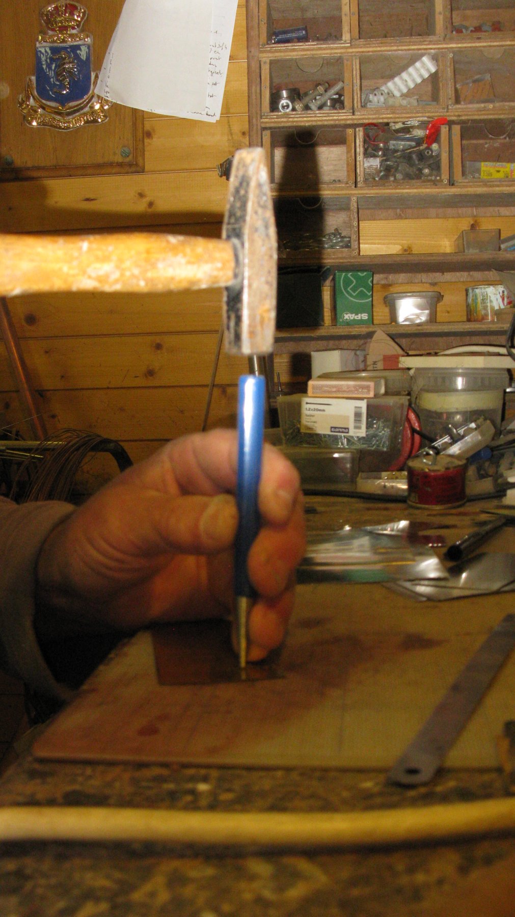
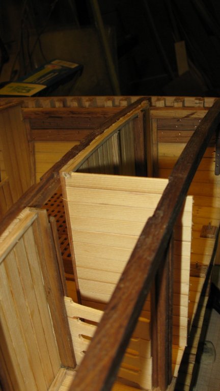
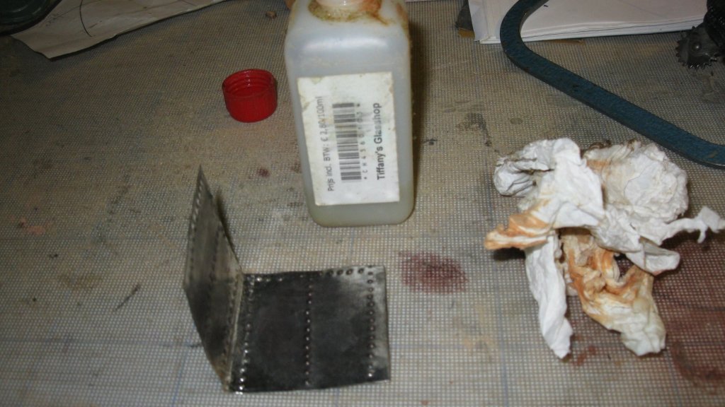
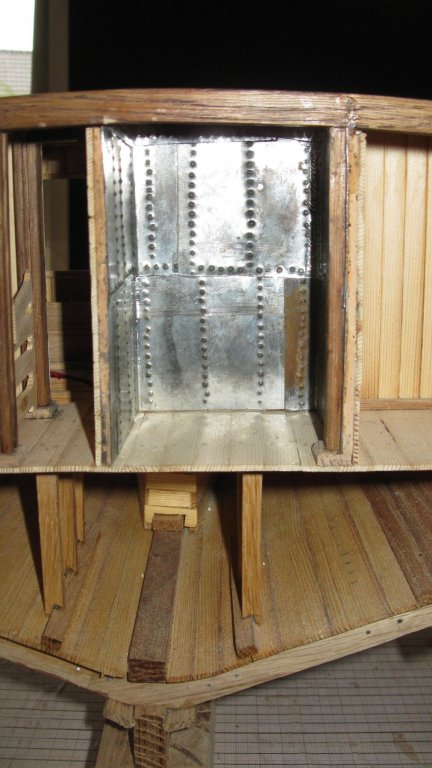
The deck beams which meet frames are reinforced with iron knees. I make them out of strips of brass (I apologize for the blurry images). Nail holes in the knees. After they are blackened, I nail them on the deck beam. Marking and drilling the nail holes in the hull. I will not fasten the deck beam immediately to the model before I made some progress to the fish hold. The fish hold could be divided in small cubus-shaped compartments by mean of removable planks to stow away the fish with ice. In the fish hold stood wooden vertical pillars with slots in it to hold the planks. I will only place some planks to make clear how it was like. From the late 19th century on, fishermen who went for a couple of days to sea stored their catch between layers of ice. In those days winter ice was shipped from Norway to our fishery ports. After the first World War fishermen took factory made ice with them. On certain vessels they used some of the fish compartments to store ice. On other boats there was a special insulated ice container on board. For this cross section Mr. Verleene relies to the construction of a Flemish (Belgian) fishing vessel. The icebox was made of a slat construction with cork plates in between and that all was covered with galvanized or zinc plates. The box could contain approx. 1200 kg ice. I start by making the container sides. They are made off horizontal paneling. To give it all a bit of initial strength I glue a piece of waste paper on the inside of the walls. It will soon be covered by the inner lining of the icebox. I don't have to imitate the cork insulation material, I use real cork, namely a wine cork. I saw the cork in slices. I glue a cork layer on the edge of the icebox wall. The galvanized plates are made of tin-plate. The plates were nailed on the slat construction. I imitate the nails by punching them in the plate. The tin is a bit too glossy, therefore I rub it in with tiffany patina to give it a zinc look. Gluing the plates. The ice compartment is entirely plated. The plate right below is corroded due to a bit too long contact with the tiffany patina. I will sand it slightly.


- 219 replies
-
- 18
-
-
- smack
- cross-section
- (and 2 more)
-
Thanks for the reactions, Carl and Patrick. Hereby I want to express also all my best wishes for a healthy and prosperous 2019 for all followers and likers.

- 219 replies
-
- 2
-
-
- smack
- cross-section
- (and 2 more)
-
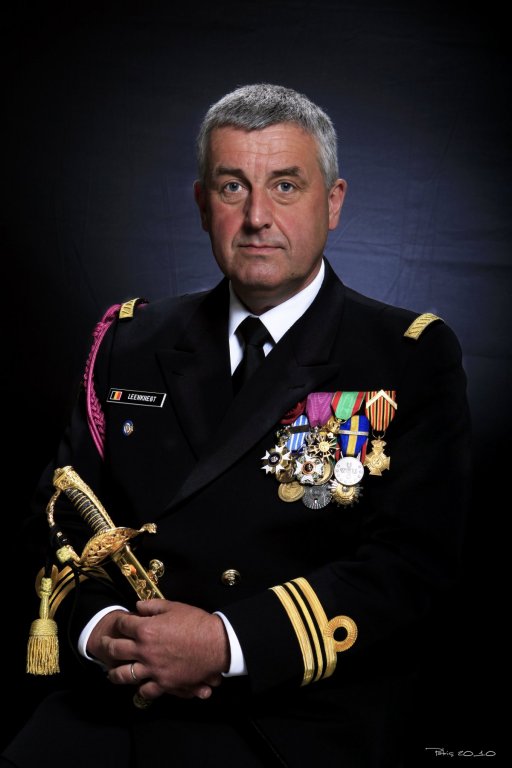
Hey Doris,
I sign up to become a member of HMS Royal Katherine. Here you find my last official picture before my retirement from the Belgian Navy some 5 years ago. It is really amazing what you are doing with HMS Royal Katherine. Every post of you contains new surprises. I wish you good luck with the further development of your project.
-
HMS ROYAL KATHERINE 1664 by Doris - 1/55 - CARD
G.L. replied to DORIS's topic in - Build logs for subjects built 1501 - 1750
Doris, I would be very honored to be a crewmember of your HMS Royal Katherine. I will send you a picture.- 1,035 replies
-
- 5
-
-
- royal katherine
- ship of the line
- (and 1 more)
-
HMS ROYAL KATHERINE 1664 by Doris - 1/55 - CARD
G.L. replied to DORIS's topic in - Build logs for subjects built 1501 - 1750
Doris, I am looking very much forward to see you making the crew. What a challenge to make portraits of real existing people! Congratulations on stylish interior of the cabin.- 1,035 replies
-
- 6
-
-
- royal katherine
- ship of the line
- (and 1 more)
-
ancre La Salamandre by tadheus - 1:24
G.L. replied to tadheus's topic in - Build logs for subjects built 1751 - 1800
Pawel, Long ago since we heard something about you and the Salamandre. Glad you are back. -
Alexander, Did you make your carvings with a chisel, a knife or a rotary tool? Your boeier yacht becomes a real beauty.
-
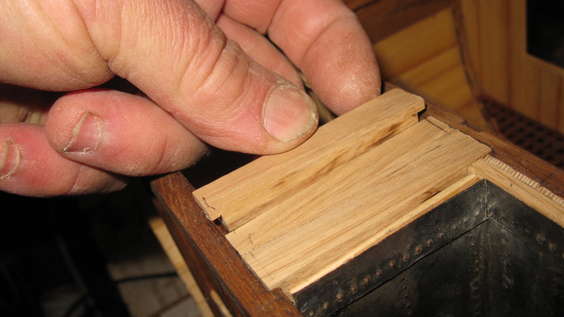
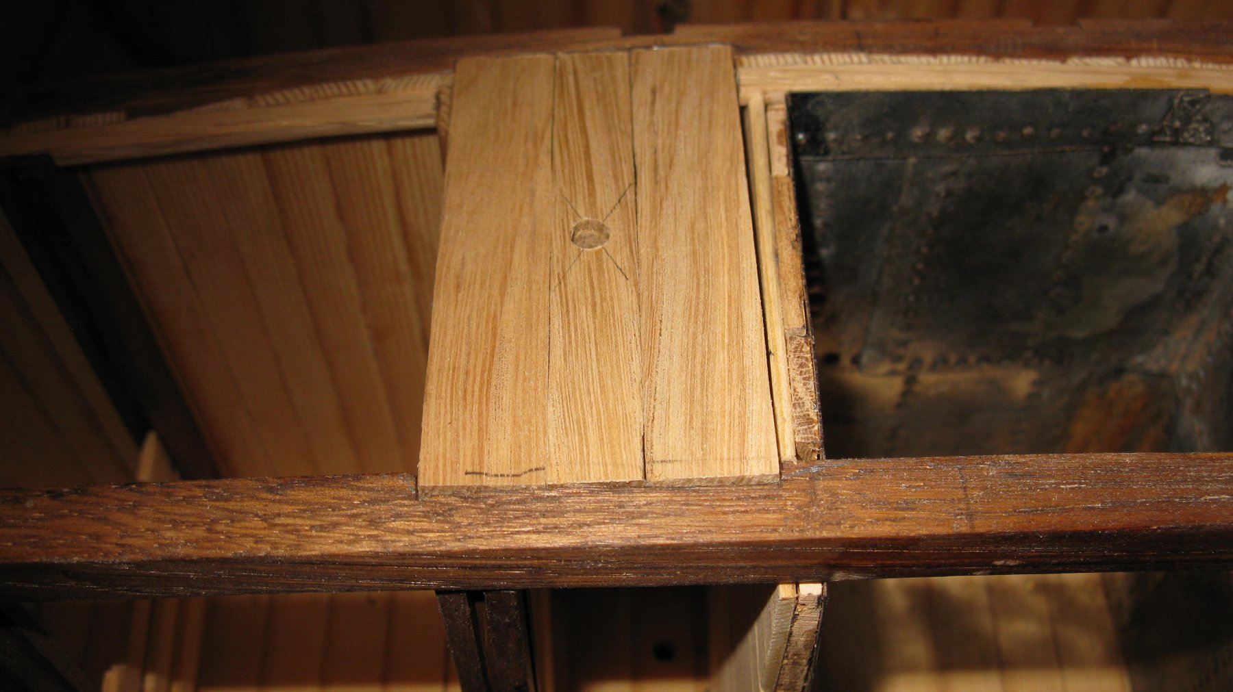
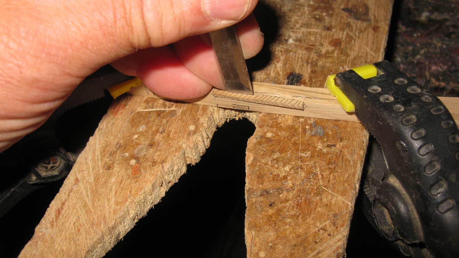
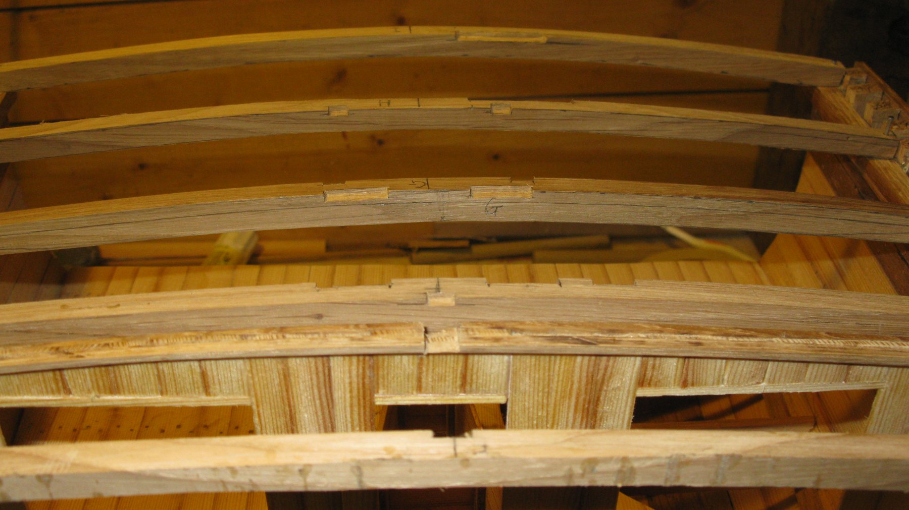
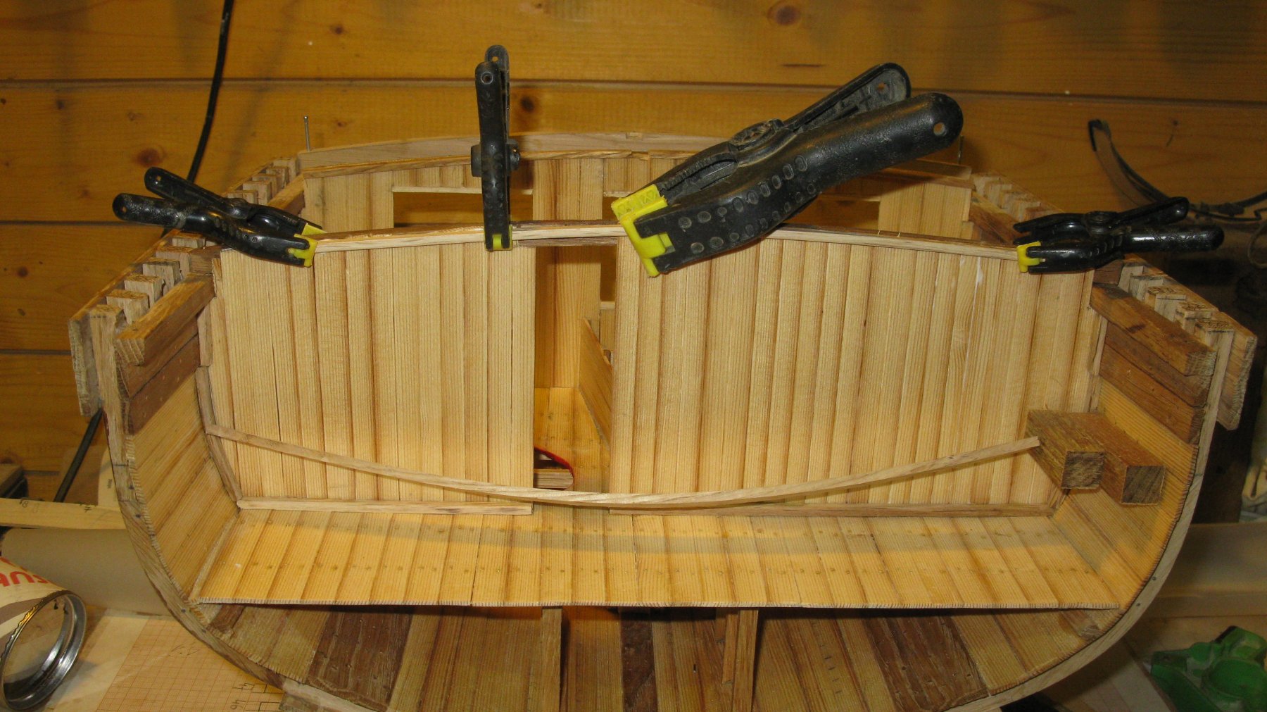
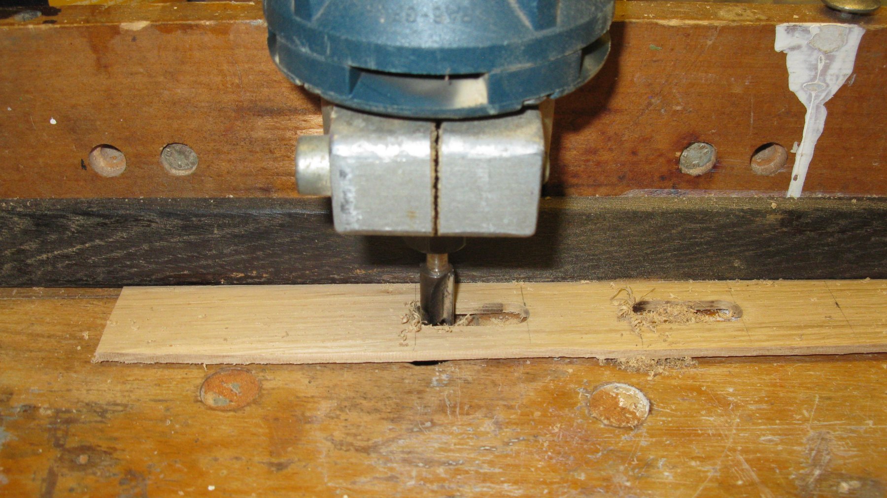
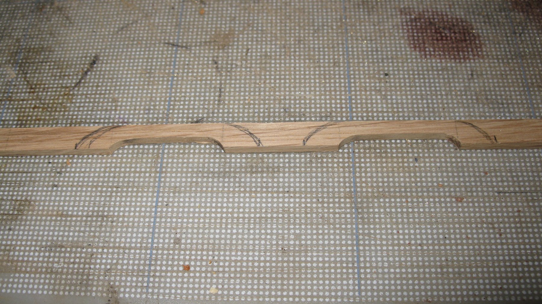
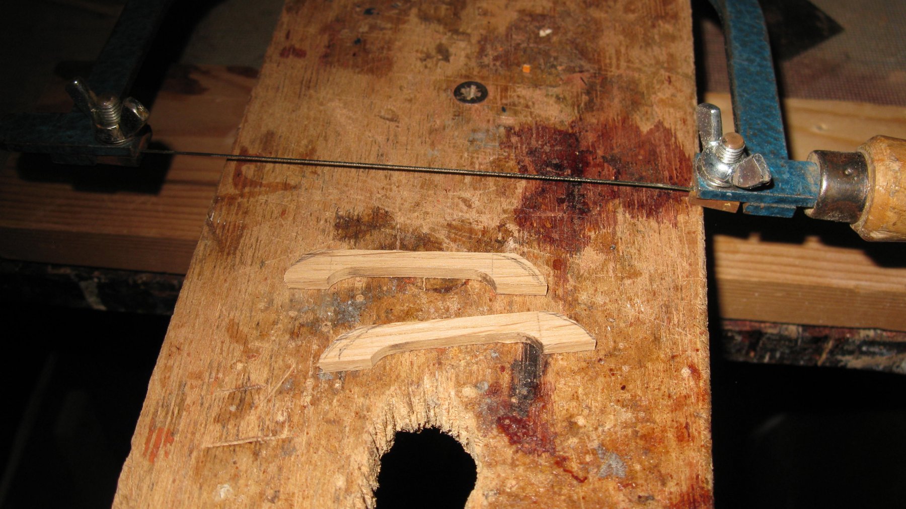
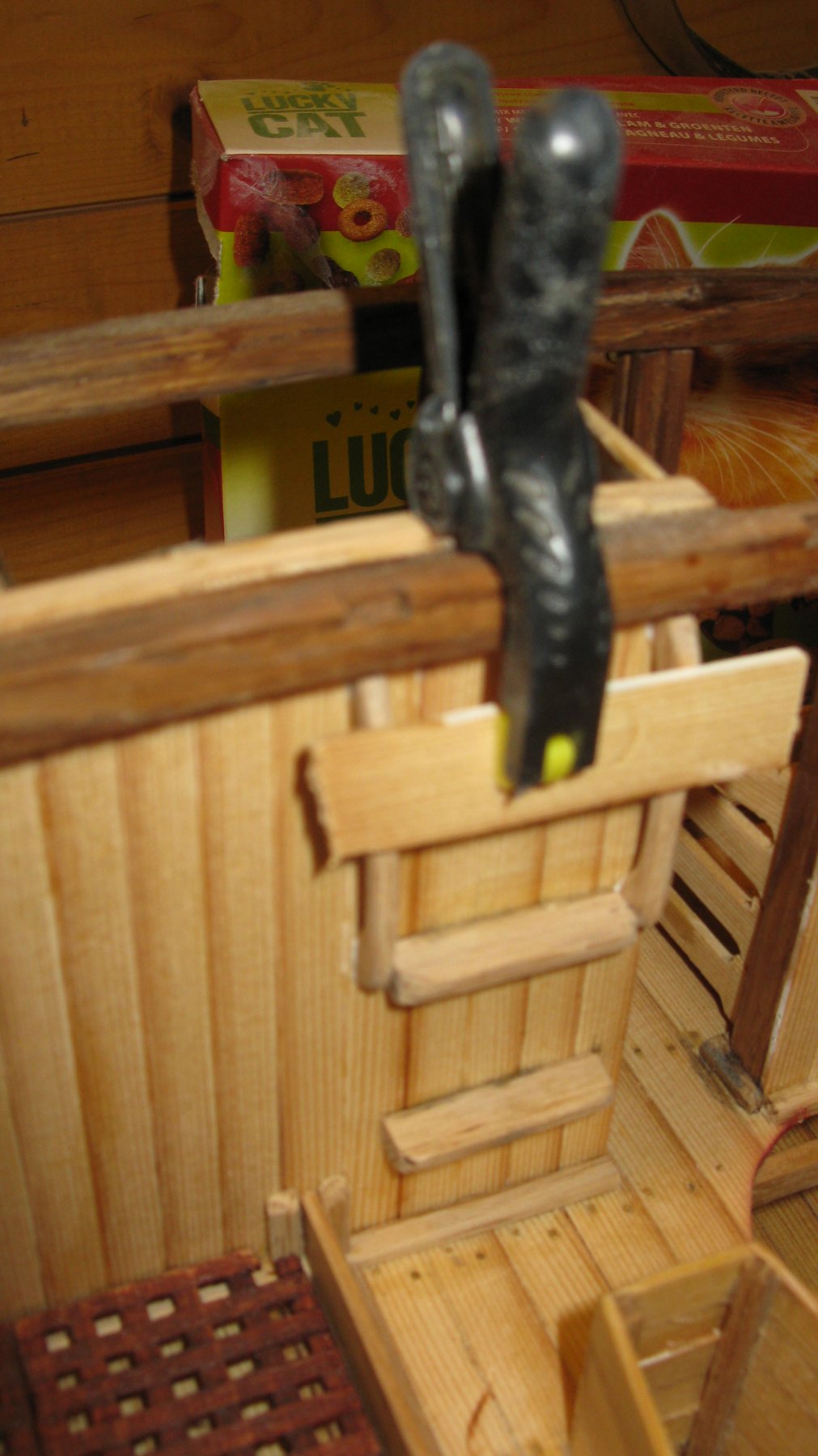
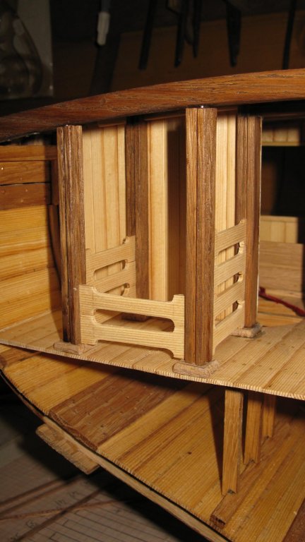
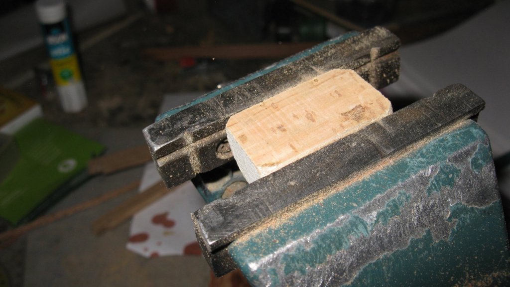
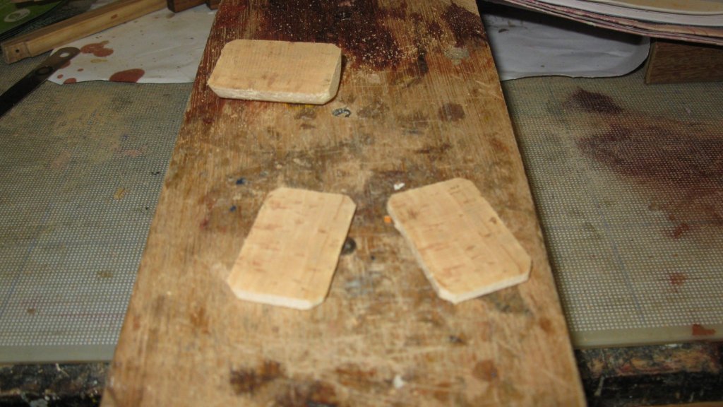
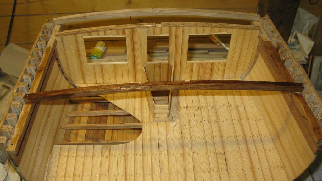
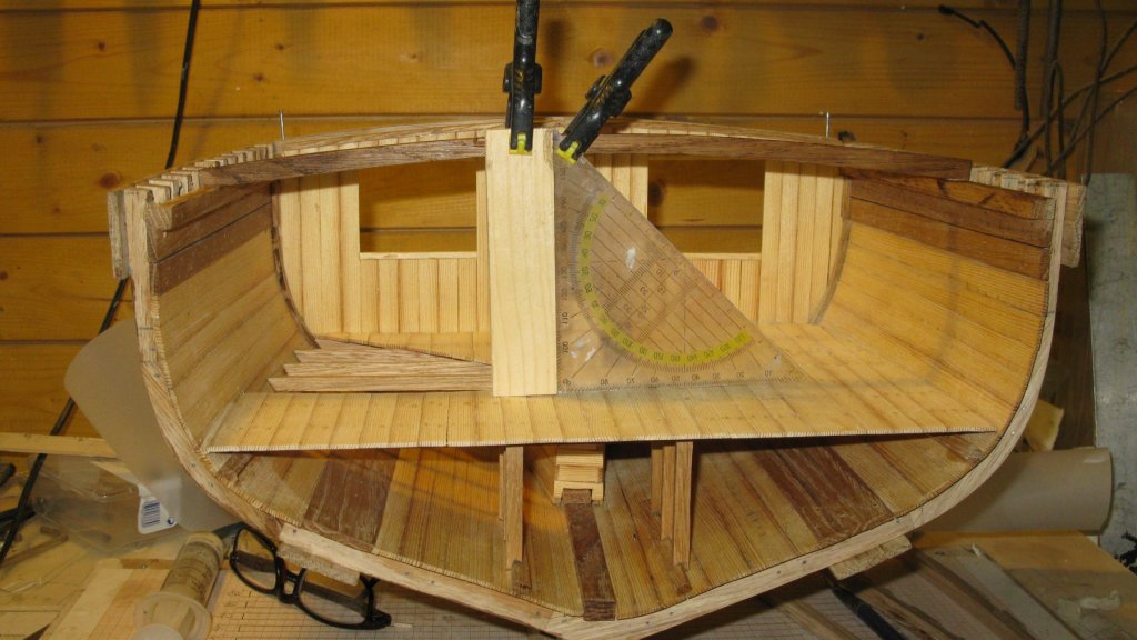
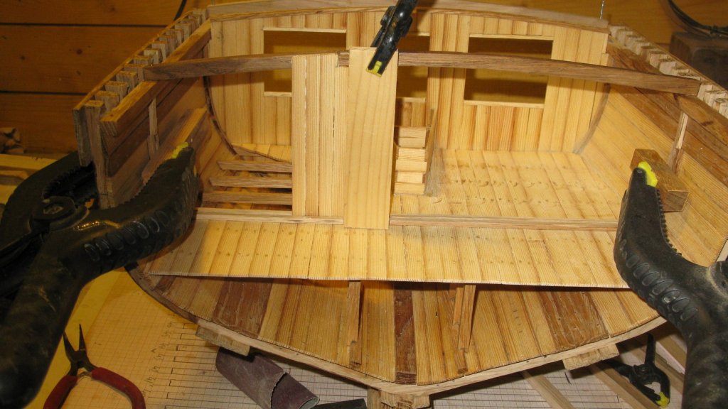
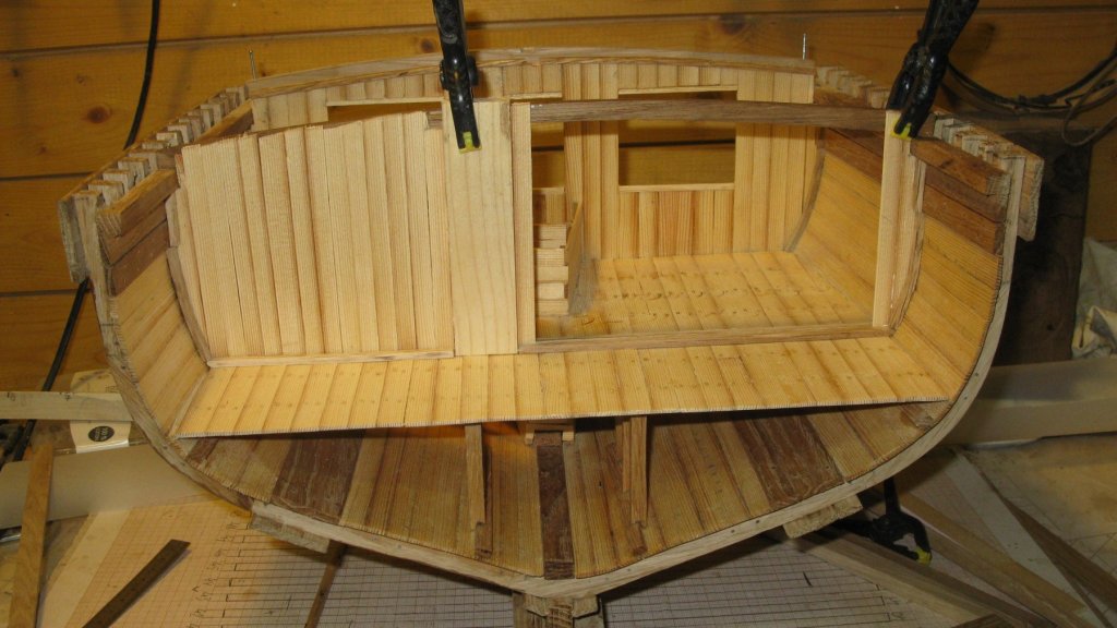
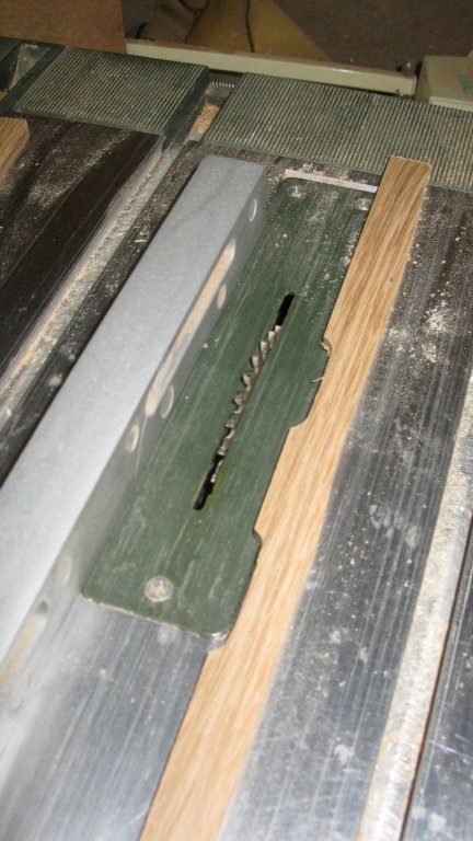
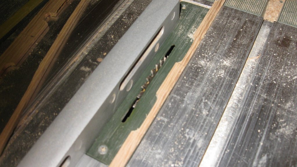
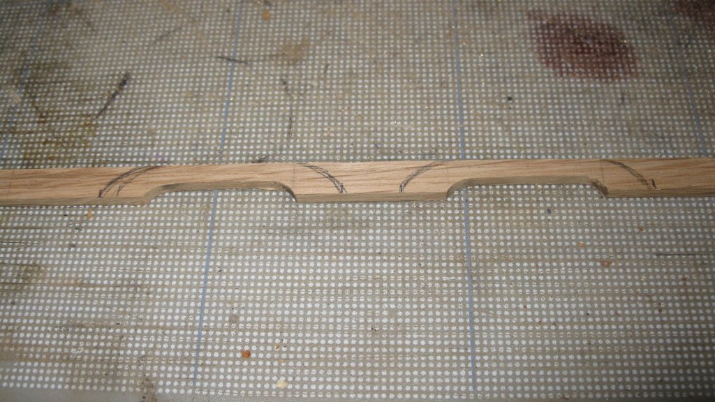
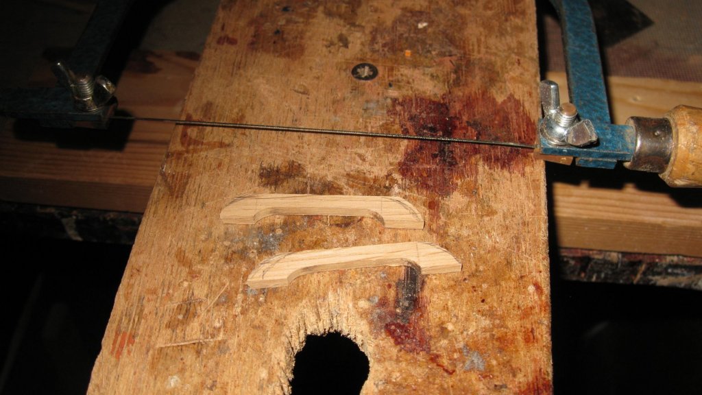
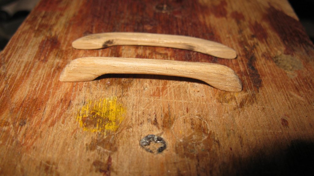
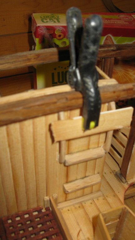
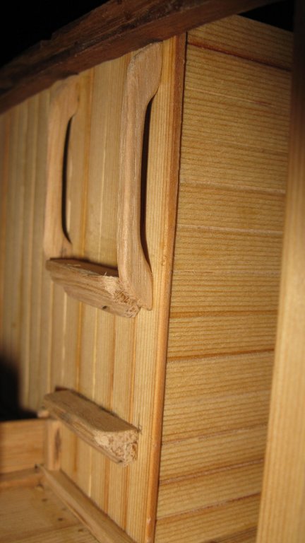
Part 14: The after bulkhead Some carlings have to be placed on the deck beams, therefore I have to make some notches in the beams. I make them using wood chisels. All the notches are made. The beams are just laying on the model without glue. Before starting to build the bulkhead that separates the equipment store from the fish hold, I stain the deck beams and place the one which will support the bulkhead definitively. Left of the middle of the bulkhead is a passageway. I place a provisory shelf with the same dimensions as the passageway. Building the bulkhead to the left and to the right of the passageway. Below the hatch of the equipment store there are two steps on the bulwark to descend in the store. I forgot to make pictures of the making of them. Because I find difficult to use the steps without a handrail I will place handrails although it is not described in the practicum. I mill some 3 cm long slots in a piece of 3 mm thick oak. I saw the plank in the middle, and then to the right width. I saw the shape of the handrails, and round off the angled sides with sandpaper. Gluing the handrails. Like this it is much easier for my crew to use the steps.


- 219 replies
-
- 12
-
-
- smack
- cross-section
- (and 2 more)
-
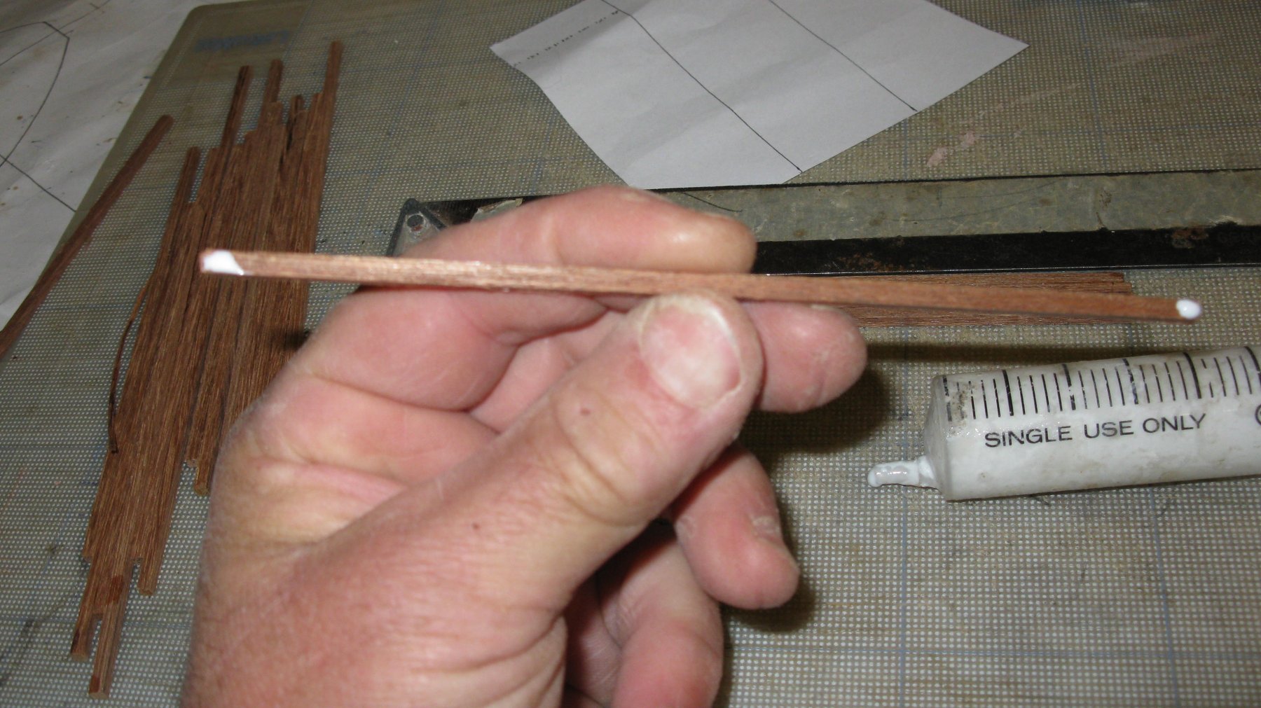
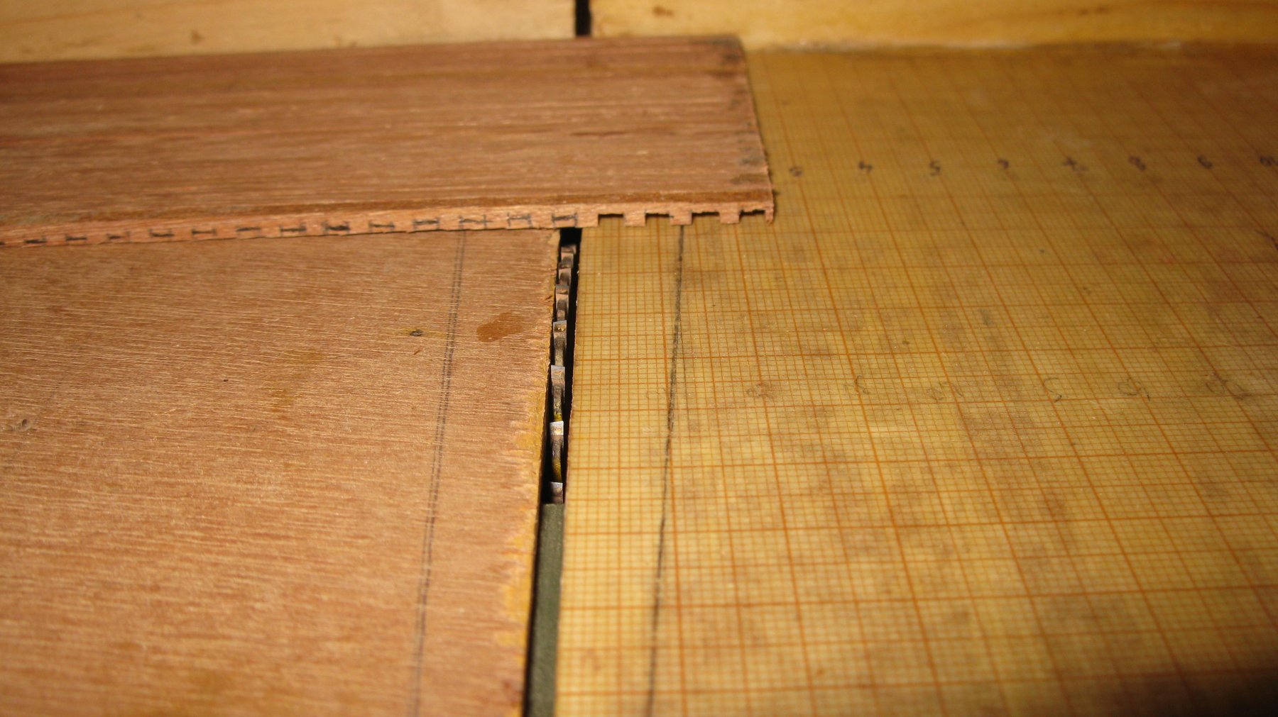
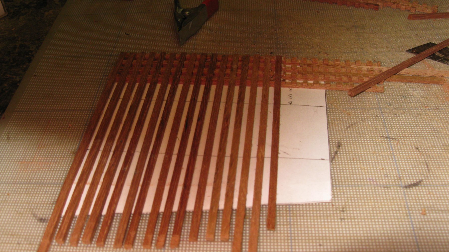
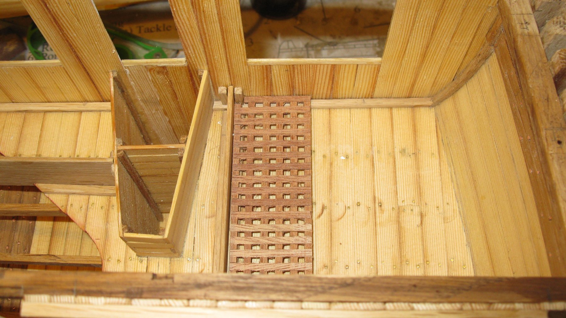
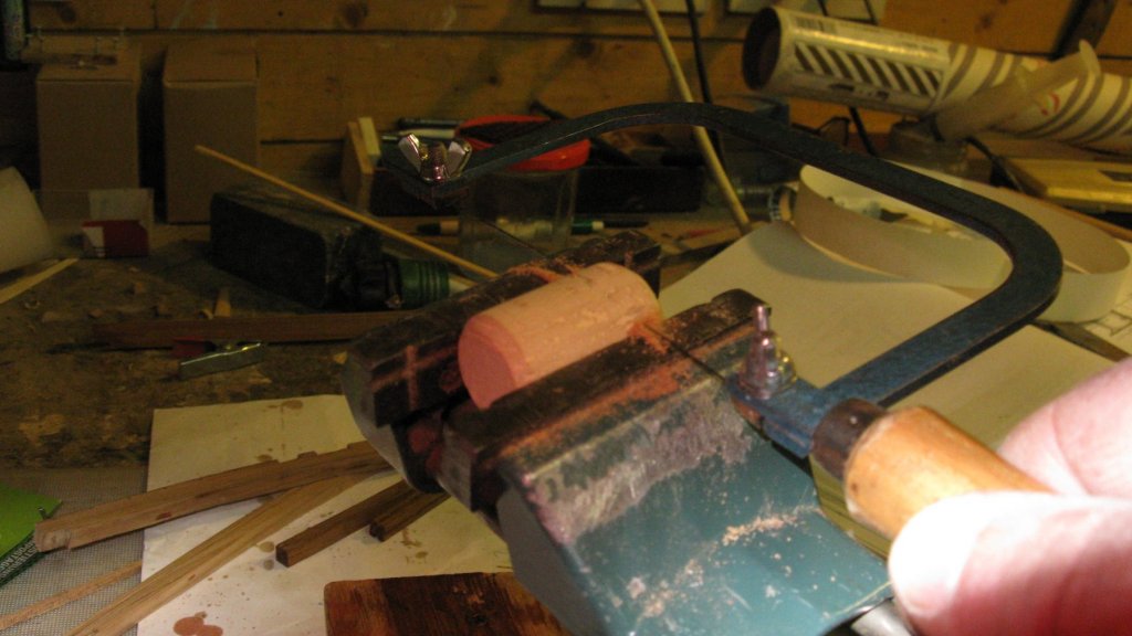
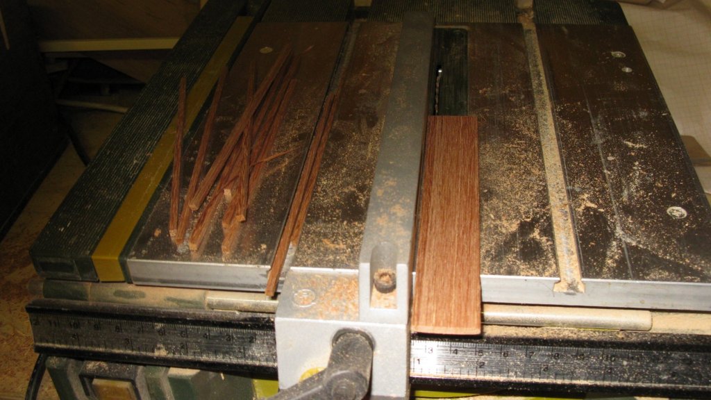
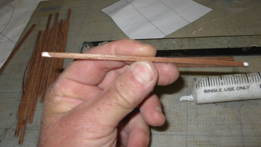
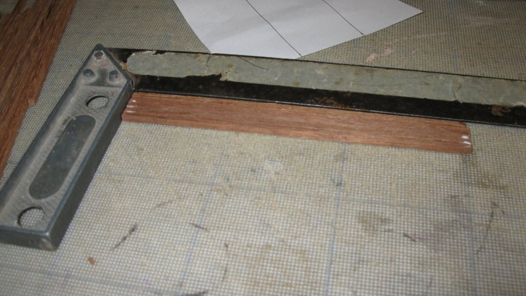
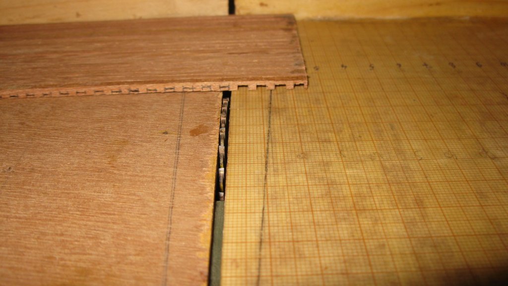
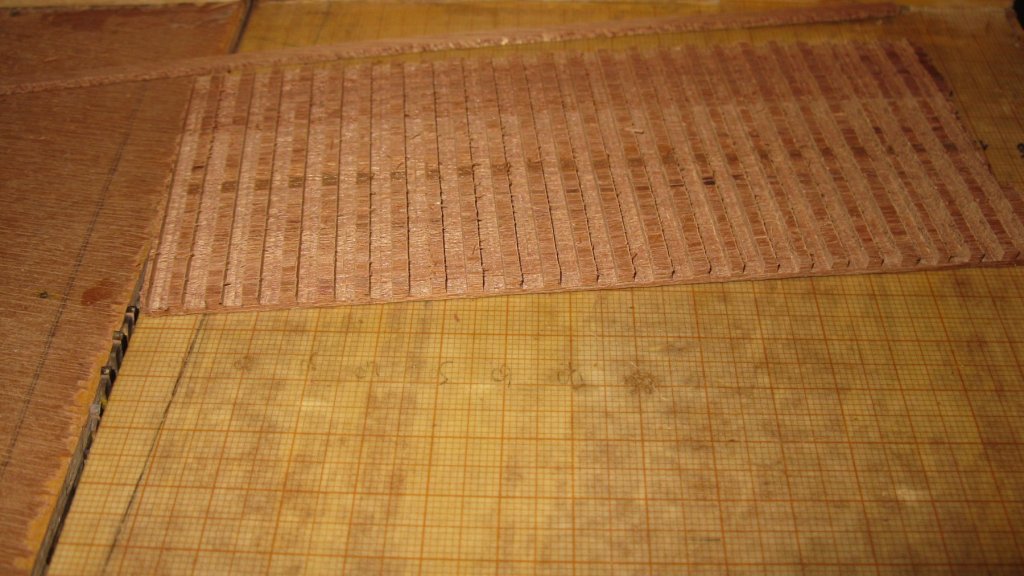
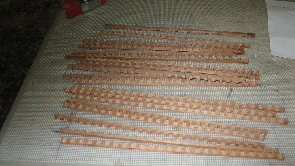
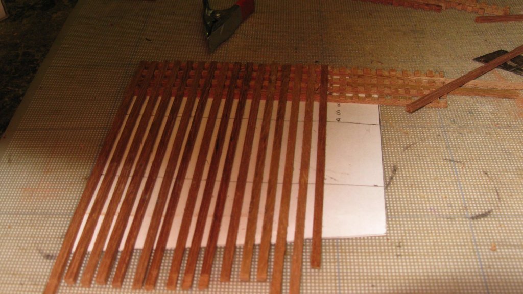
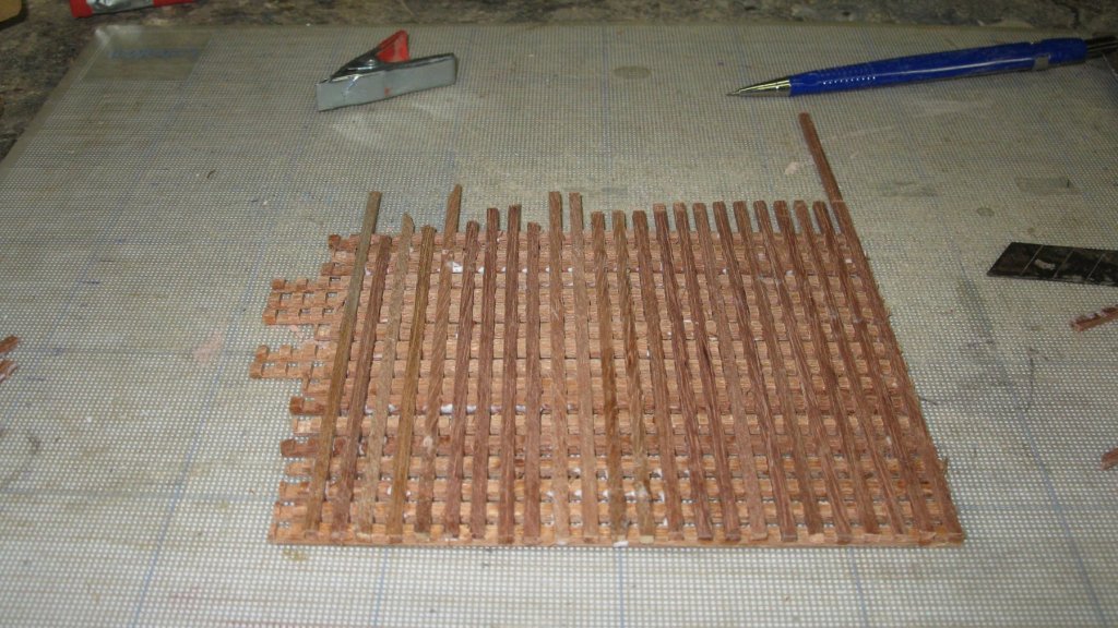
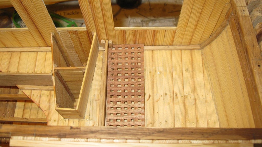
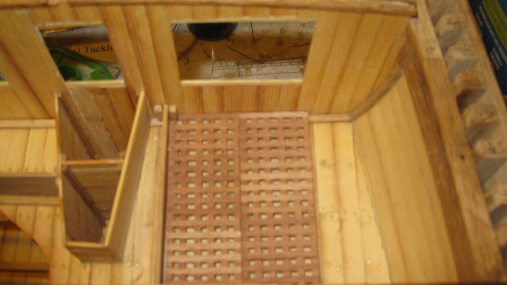
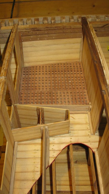
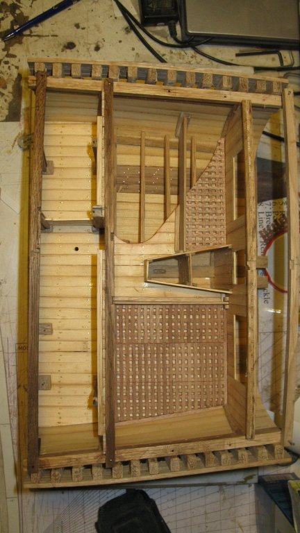
Thanks Carl and Patrick and all those who pushed the 'like button'. Here is the progress of last week: When I showed the progress on my cross section to my modelers friends, one of them asked me if there would be gratings in the rope- and fender stores. I said him that it was not provided in the practicum. Afterwards I thought about it and I realized that it would make sense if the ropes and rope fenders were laying on gratings to protect them against mold. And also very important: a grating would hide the mess I made of my deck. I saw 3mm strips out of a 3mm thick mahogany plank. I glue them together as one surface with a droplet of glue at each side. In the whole of strips, I saw at 3mm intervals 1.5mm deep and 3 mm wide slits I disassemble the strip again, using a cutter knife. I start gluing 3mm x 1.5mm strips in the slits. The grating, ready to be sawn in different parts and to be sanded. I suppose that the grating could be brought outside therefore I make the grating for the trawl warp storage in three parts which can pass each through the hatch. One part in place Two parts in place. All three parts in place. The grating of the rope fender storage, partly cut away.
- 219 replies
-
- 8
-
-
- smack
- cross-section
- (and 2 more)