
Supplies of the Ship Modeler's Handbook are running out. Get your copy NOW before they are gone! Click on photo to order.
×
Chuck
-
Posts
9,449 -
Joined
-
Last visited
Reputation Activity
-

 Chuck got a reaction from FrankWouts in Sloop Speedwell 1752 by Chuck - Ketch Rigged Sloop - POF - prototype build
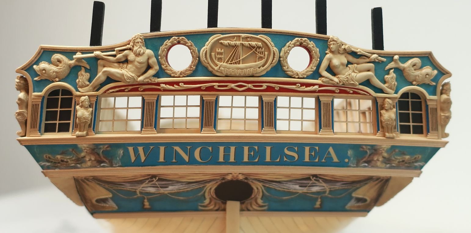
The hawse holes can be complex but if you spend a lot of time preparing and measuring it will go smoothly. Before I begin describing my process here is a look at the contemporary model. You can see many close up details here.
I started by preparing some new templates. They are very much like the other templates but I wanted to add some other reference lines to help me more with aligning the hawse holes. So these are the ones you want to use when you get this stage.
You will note a few things in that photo. First you will see the dashed vertical lines I added that extend up to the cap rail. These will allow you to mark the locations of the hawse holes on top of the cap rail. To do this I cut some painters tape to the width of the hawse holes and placed it on the cap rail using the template as a guide. The tape runs parallel to the keel across the cap rail.
You will also notice how I cut the hawse holes from the template so I could use it as a stencil after taping it to the hull. I also cut an opening to mark the location of the hawse hoods or naval hoods. These are the plates that sit over the planking. The template sits on top of the wales as before. The forward edge sits against the stem.
I of course cut away the molding strip on the hull before I taped the template in position. I dont want to forget to mention that. Then I traced the hawse holes onto the hull.
On the inboard side of the hull, I prepared another template specifically for the hawse holes. Note the dashed lines again that extend to the cap rail. This template was lined up with the tape I placed across the cap rail. This will be the path I plan to drill through the hull for the hawse holes. This was a lot of measuring and planning to come up with these templates but it all worked out well. Just trace the hawse holes on the inboard side as well. Note how the template is sitting on the deck which establishes the correct height...I hope.
I didnt take any pictures right after drilling the hawse holes. I cant believe I forgot to do it. But let me explain the process. I drilled them out using progressively larger drill bits. I drilled from both sides. I drilled half way through from the front and then switched to inboard. I drilled half way through until the holes met in the middle and the first small hole was clear and through. Then I switched to a slightly larger drill bit and repeated the process. I increased them until the hawse holes were almost full size and then I switched to a round file to clean them up and enlarge them further.
THE ENTIRE time while drilling from the outboard side I used the blue tape on the top of the cap rail to guide the drill bit at the same angle. Following the keel. The hawse holes are almost level in height inboard and outboard with only a slight upward angle needed as you drill from the outboard side. A very slight angle. Not to worry if its not exact because when you dill from the inboard side to meet the outside hole it should all meet up decently.
I touched up the red paint inboard and used a soft pencil to darken the insides of the hawse holes black...to represent lead or tin I suppose.
Next up was to add the Hawse hoods or Naval hoods on the outboard side. These are made in two layers. They are laser cut and on the outermost end is a laser etched detail. This small etched detail wouldnt be difficult to carve with a sharp chisel. But I just assume etch it onto the ends. This means you must clean up the laser char from this "stepped" detail. I used a small flat needle file. It doesnt have to be perfectly clean either. Just do the best you can. Mine isnt perfect by any means and this little bt of char will actually accentuate the carved detail. Look at the photo of the contemporary model to see it on the original. The parts on the left are not yet cleaned.
The two layers are glued together carefully. The circles for the hawse holes are registered together. But a little tip....while gluing the two layers you can actually pre bend the hoods so they will stay bent and curved once the glue dries. Its hard to see this in the photo but the one on the right is curved to almost match the hull curvature exactly. This will make it so much easier to glue onto the hull.
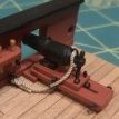
Here you can see the two layered assembly glued onto the hull. Please note that after gluing the two layers together the inside edge against the stem must be beveled. I also cut these pieces a but longer (not by much) so you can line them up with your hawse holes drilled through the hull. Just carefully bevel the edge a little at time until as you are test fitting it on the model it the hawse holes line up. The holes themselves are also slightly smaller on this so you will have even more wiggle room to enlarge them after this is glued on the model. I think they look pretty good and look quite a bit like the contemporary model.
Lastly...the bolster. This piece is slightly thicker and not long enough to bend easily. So I laser cut it on even thicker boxwood stock. Its easier to sand the curve into the back side rather than bend it to fit on the hull. Once the bolster sits nicely on the hull and the curve matches, you can sand the outside to match. This will leave the overall thickness at about 3/64". Maybe slightly more.
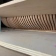
Round off the top edges and sides but dont touch the hawse hole cut-aways just yet. This will be done after you glue the bolsters on the model. You will notice the oddball shape of the hawse hole cut-aways. They dont look like half circles. This is on purpose. Remember the hawse holes are drilled through parallel to the keel. So these weird shaped half holes are shaped like l=this so you can file them to the proper shape. Use a round file to open them up to match the angle of your hawse holes through the bulwarks. I hope that makes sense. When initially gluing the bolster on the hull, line up the iboard side to match the profile of your hawse holes. Just like in the photo. Then use your file to shape them.
They will or should be opened up to look like this. The holes were touched up and blackened with a soft pencil.
-

 Chuck got a reaction from Hubac's Historian in Sloop Speedwell 1752 by Chuck - Ketch Rigged Sloop - POF - prototype build
The hawse holes can be complex but if you spend a lot of time preparing and measuring it will go smoothly. Before I begin describing my process here is a look at the contemporary model. You can see many close up details here.
I started by preparing some new templates. They are very much like the other templates but I wanted to add some other reference lines to help me more with aligning the hawse holes. So these are the ones you want to use when you get this stage.
You will note a few things in that photo. First you will see the dashed vertical lines I added that extend up to the cap rail. These will allow you to mark the locations of the hawse holes on top of the cap rail. To do this I cut some painters tape to the width of the hawse holes and placed it on the cap rail using the template as a guide. The tape runs parallel to the keel across the cap rail.
You will also notice how I cut the hawse holes from the template so I could use it as a stencil after taping it to the hull. I also cut an opening to mark the location of the hawse hoods or naval hoods. These are the plates that sit over the planking. The template sits on top of the wales as before. The forward edge sits against the stem.
I of course cut away the molding strip on the hull before I taped the template in position. I dont want to forget to mention that. Then I traced the hawse holes onto the hull.
On the inboard side of the hull, I prepared another template specifically for the hawse holes. Note the dashed lines again that extend to the cap rail. This template was lined up with the tape I placed across the cap rail. This will be the path I plan to drill through the hull for the hawse holes. This was a lot of measuring and planning to come up with these templates but it all worked out well. Just trace the hawse holes on the inboard side as well. Note how the template is sitting on the deck which establishes the correct height...I hope.
I didnt take any pictures right after drilling the hawse holes. I cant believe I forgot to do it. But let me explain the process. I drilled them out using progressively larger drill bits. I drilled from both sides. I drilled half way through from the front and then switched to inboard. I drilled half way through until the holes met in the middle and the first small hole was clear and through. Then I switched to a slightly larger drill bit and repeated the process. I increased them until the hawse holes were almost full size and then I switched to a round file to clean them up and enlarge them further.
THE ENTIRE time while drilling from the outboard side I used the blue tape on the top of the cap rail to guide the drill bit at the same angle. Following the keel. The hawse holes are almost level in height inboard and outboard with only a slight upward angle needed as you drill from the outboard side. A very slight angle. Not to worry if its not exact because when you dill from the inboard side to meet the outside hole it should all meet up decently.
I touched up the red paint inboard and used a soft pencil to darken the insides of the hawse holes black...to represent lead or tin I suppose.
Next up was to add the Hawse hoods or Naval hoods on the outboard side. These are made in two layers. They are laser cut and on the outermost end is a laser etched detail. This small etched detail wouldnt be difficult to carve with a sharp chisel. But I just assume etch it onto the ends. This means you must clean up the laser char from this "stepped" detail. I used a small flat needle file. It doesnt have to be perfectly clean either. Just do the best you can. Mine isnt perfect by any means and this little bt of char will actually accentuate the carved detail. Look at the photo of the contemporary model to see it on the original. The parts on the left are not yet cleaned.
The two layers are glued together carefully. The circles for the hawse holes are registered together. But a little tip....while gluing the two layers you can actually pre bend the hoods so they will stay bent and curved once the glue dries. Its hard to see this in the photo but the one on the right is curved to almost match the hull curvature exactly. This will make it so much easier to glue onto the hull.
Here you can see the two layered assembly glued onto the hull. Please note that after gluing the two layers together the inside edge against the stem must be beveled. I also cut these pieces a but longer (not by much) so you can line them up with your hawse holes drilled through the hull. Just carefully bevel the edge a little at time until as you are test fitting it on the model it the hawse holes line up. The holes themselves are also slightly smaller on this so you will have even more wiggle room to enlarge them after this is glued on the model. I think they look pretty good and look quite a bit like the contemporary model.
Lastly...the bolster. This piece is slightly thicker and not long enough to bend easily. So I laser cut it on even thicker boxwood stock. Its easier to sand the curve into the back side rather than bend it to fit on the hull. Once the bolster sits nicely on the hull and the curve matches, you can sand the outside to match. This will leave the overall thickness at about 3/64". Maybe slightly more.
Round off the top edges and sides but dont touch the hawse hole cut-aways just yet. This will be done after you glue the bolsters on the model. You will notice the oddball shape of the hawse hole cut-aways. They dont look like half circles. This is on purpose. Remember the hawse holes are drilled through parallel to the keel. So these weird shaped half holes are shaped like l=this so you can file them to the proper shape. Use a round file to open them up to match the angle of your hawse holes through the bulwarks. I hope that makes sense. When initially gluing the bolster on the hull, line up the iboard side to match the profile of your hawse holes. Just like in the photo. Then use your file to shape them.
They will or should be opened up to look like this. The holes were touched up and blackened with a soft pencil.
-
 Chuck got a reaction from scrubbyj427 in Sloop Speedwell 1752 by Chuck - Ketch Rigged Sloop - POF - prototype build
The hawse holes can be complex but if you spend a lot of time preparing and measuring it will go smoothly. Before I begin describing my process here is a look at the contemporary model. You can see many close up details here.
I started by preparing some new templates. They are very much like the other templates but I wanted to add some other reference lines to help me more with aligning the hawse holes. So these are the ones you want to use when you get this stage.
You will note a few things in that photo. First you will see the dashed vertical lines I added that extend up to the cap rail. These will allow you to mark the locations of the hawse holes on top of the cap rail. To do this I cut some painters tape to the width of the hawse holes and placed it on the cap rail using the template as a guide. The tape runs parallel to the keel across the cap rail.
You will also notice how I cut the hawse holes from the template so I could use it as a stencil after taping it to the hull. I also cut an opening to mark the location of the hawse hoods or naval hoods. These are the plates that sit over the planking. The template sits on top of the wales as before. The forward edge sits against the stem.
I of course cut away the molding strip on the hull before I taped the template in position. I dont want to forget to mention that. Then I traced the hawse holes onto the hull.
On the inboard side of the hull, I prepared another template specifically for the hawse holes. Note the dashed lines again that extend to the cap rail. This template was lined up with the tape I placed across the cap rail. This will be the path I plan to drill through the hull for the hawse holes. This was a lot of measuring and planning to come up with these templates but it all worked out well. Just trace the hawse holes on the inboard side as well. Note how the template is sitting on the deck which establishes the correct height...I hope.
I didnt take any pictures right after drilling the hawse holes. I cant believe I forgot to do it. But let me explain the process. I drilled them out using progressively larger drill bits. I drilled from both sides. I drilled half way through from the front and then switched to inboard. I drilled half way through until the holes met in the middle and the first small hole was clear and through. Then I switched to a slightly larger drill bit and repeated the process. I increased them until the hawse holes were almost full size and then I switched to a round file to clean them up and enlarge them further.
THE ENTIRE time while drilling from the outboard side I used the blue tape on the top of the cap rail to guide the drill bit at the same angle. Following the keel. The hawse holes are almost level in height inboard and outboard with only a slight upward angle needed as you drill from the outboard side. A very slight angle. Not to worry if its not exact because when you dill from the inboard side to meet the outside hole it should all meet up decently.
I touched up the red paint inboard and used a soft pencil to darken the insides of the hawse holes black...to represent lead or tin I suppose.
Next up was to add the Hawse hoods or Naval hoods on the outboard side. These are made in two layers. They are laser cut and on the outermost end is a laser etched detail. This small etched detail wouldnt be difficult to carve with a sharp chisel. But I just assume etch it onto the ends. This means you must clean up the laser char from this "stepped" detail. I used a small flat needle file. It doesnt have to be perfectly clean either. Just do the best you can. Mine isnt perfect by any means and this little bt of char will actually accentuate the carved detail. Look at the photo of the contemporary model to see it on the original. The parts on the left are not yet cleaned.
The two layers are glued together carefully. The circles for the hawse holes are registered together. But a little tip....while gluing the two layers you can actually pre bend the hoods so they will stay bent and curved once the glue dries. Its hard to see this in the photo but the one on the right is curved to almost match the hull curvature exactly. This will make it so much easier to glue onto the hull.
Here you can see the two layered assembly glued onto the hull. Please note that after gluing the two layers together the inside edge against the stem must be beveled. I also cut these pieces a but longer (not by much) so you can line them up with your hawse holes drilled through the hull. Just carefully bevel the edge a little at time until as you are test fitting it on the model it the hawse holes line up. The holes themselves are also slightly smaller on this so you will have even more wiggle room to enlarge them after this is glued on the model. I think they look pretty good and look quite a bit like the contemporary model.
Lastly...the bolster. This piece is slightly thicker and not long enough to bend easily. So I laser cut it on even thicker boxwood stock. Its easier to sand the curve into the back side rather than bend it to fit on the hull. Once the bolster sits nicely on the hull and the curve matches, you can sand the outside to match. This will leave the overall thickness at about 3/64". Maybe slightly more.
Round off the top edges and sides but dont touch the hawse hole cut-aways just yet. This will be done after you glue the bolsters on the model. You will notice the oddball shape of the hawse hole cut-aways. They dont look like half circles. This is on purpose. Remember the hawse holes are drilled through parallel to the keel. So these weird shaped half holes are shaped like l=this so you can file them to the proper shape. Use a round file to open them up to match the angle of your hawse holes through the bulwarks. I hope that makes sense. When initially gluing the bolster on the hull, line up the iboard side to match the profile of your hawse holes. Just like in the photo. Then use your file to shape them.
They will or should be opened up to look like this. The holes were touched up and blackened with a soft pencil.
-
 Chuck got a reaction from BenD in Sloop Speedwell 1752 by Chuck - Ketch Rigged Sloop - POF - prototype build
The hawse holes can be complex but if you spend a lot of time preparing and measuring it will go smoothly. Before I begin describing my process here is a look at the contemporary model. You can see many close up details here.
I started by preparing some new templates. They are very much like the other templates but I wanted to add some other reference lines to help me more with aligning the hawse holes. So these are the ones you want to use when you get this stage.
You will note a few things in that photo. First you will see the dashed vertical lines I added that extend up to the cap rail. These will allow you to mark the locations of the hawse holes on top of the cap rail. To do this I cut some painters tape to the width of the hawse holes and placed it on the cap rail using the template as a guide. The tape runs parallel to the keel across the cap rail.
You will also notice how I cut the hawse holes from the template so I could use it as a stencil after taping it to the hull. I also cut an opening to mark the location of the hawse hoods or naval hoods. These are the plates that sit over the planking. The template sits on top of the wales as before. The forward edge sits against the stem.
I of course cut away the molding strip on the hull before I taped the template in position. I dont want to forget to mention that. Then I traced the hawse holes onto the hull.
On the inboard side of the hull, I prepared another template specifically for the hawse holes. Note the dashed lines again that extend to the cap rail. This template was lined up with the tape I placed across the cap rail. This will be the path I plan to drill through the hull for the hawse holes. This was a lot of measuring and planning to come up with these templates but it all worked out well. Just trace the hawse holes on the inboard side as well. Note how the template is sitting on the deck which establishes the correct height...I hope.
I didnt take any pictures right after drilling the hawse holes. I cant believe I forgot to do it. But let me explain the process. I drilled them out using progressively larger drill bits. I drilled from both sides. I drilled half way through from the front and then switched to inboard. I drilled half way through until the holes met in the middle and the first small hole was clear and through. Then I switched to a slightly larger drill bit and repeated the process. I increased them until the hawse holes were almost full size and then I switched to a round file to clean them up and enlarge them further.
THE ENTIRE time while drilling from the outboard side I used the blue tape on the top of the cap rail to guide the drill bit at the same angle. Following the keel. The hawse holes are almost level in height inboard and outboard with only a slight upward angle needed as you drill from the outboard side. A very slight angle. Not to worry if its not exact because when you dill from the inboard side to meet the outside hole it should all meet up decently.
I touched up the red paint inboard and used a soft pencil to darken the insides of the hawse holes black...to represent lead or tin I suppose.
Next up was to add the Hawse hoods or Naval hoods on the outboard side. These are made in two layers. They are laser cut and on the outermost end is a laser etched detail. This small etched detail wouldnt be difficult to carve with a sharp chisel. But I just assume etch it onto the ends. This means you must clean up the laser char from this "stepped" detail. I used a small flat needle file. It doesnt have to be perfectly clean either. Just do the best you can. Mine isnt perfect by any means and this little bt of char will actually accentuate the carved detail. Look at the photo of the contemporary model to see it on the original. The parts on the left are not yet cleaned.
The two layers are glued together carefully. The circles for the hawse holes are registered together. But a little tip....while gluing the two layers you can actually pre bend the hoods so they will stay bent and curved once the glue dries. Its hard to see this in the photo but the one on the right is curved to almost match the hull curvature exactly. This will make it so much easier to glue onto the hull.
Here you can see the two layered assembly glued onto the hull. Please note that after gluing the two layers together the inside edge against the stem must be beveled. I also cut these pieces a but longer (not by much) so you can line them up with your hawse holes drilled through the hull. Just carefully bevel the edge a little at time until as you are test fitting it on the model it the hawse holes line up. The holes themselves are also slightly smaller on this so you will have even more wiggle room to enlarge them after this is glued on the model. I think they look pretty good and look quite a bit like the contemporary model.
Lastly...the bolster. This piece is slightly thicker and not long enough to bend easily. So I laser cut it on even thicker boxwood stock. Its easier to sand the curve into the back side rather than bend it to fit on the hull. Once the bolster sits nicely on the hull and the curve matches, you can sand the outside to match. This will leave the overall thickness at about 3/64". Maybe slightly more.
Round off the top edges and sides but dont touch the hawse hole cut-aways just yet. This will be done after you glue the bolsters on the model. You will notice the oddball shape of the hawse hole cut-aways. They dont look like half circles. This is on purpose. Remember the hawse holes are drilled through parallel to the keel. So these weird shaped half holes are shaped like l=this so you can file them to the proper shape. Use a round file to open them up to match the angle of your hawse holes through the bulwarks. I hope that makes sense. When initially gluing the bolster on the hull, line up the iboard side to match the profile of your hawse holes. Just like in the photo. Then use your file to shape them.
They will or should be opened up to look like this. The holes were touched up and blackened with a soft pencil.
-
Chuck got a reaction from FrankWouts in Sloop Speedwell 1752 by Chuck - Ketch Rigged Sloop - POF - prototype build
Yupp....I have always done this on every ship model that I have made showing the scuppers. Works like a charm.
-
 Chuck got a reaction from marsalv in Sloop Speedwell 1752 by Chuck - Ketch Rigged Sloop - POF - prototype build
The hawse holes can be complex but if you spend a lot of time preparing and measuring it will go smoothly. Before I begin describing my process here is a look at the contemporary model. You can see many close up details here.
I started by preparing some new templates. They are very much like the other templates but I wanted to add some other reference lines to help me more with aligning the hawse holes. So these are the ones you want to use when you get this stage.
You will note a few things in that photo. First you will see the dashed vertical lines I added that extend up to the cap rail. These will allow you to mark the locations of the hawse holes on top of the cap rail. To do this I cut some painters tape to the width of the hawse holes and placed it on the cap rail using the template as a guide. The tape runs parallel to the keel across the cap rail.
You will also notice how I cut the hawse holes from the template so I could use it as a stencil after taping it to the hull. I also cut an opening to mark the location of the hawse hoods or naval hoods. These are the plates that sit over the planking. The template sits on top of the wales as before. The forward edge sits against the stem.
I of course cut away the molding strip on the hull before I taped the template in position. I dont want to forget to mention that. Then I traced the hawse holes onto the hull.
On the inboard side of the hull, I prepared another template specifically for the hawse holes. Note the dashed lines again that extend to the cap rail. This template was lined up with the tape I placed across the cap rail. This will be the path I plan to drill through the hull for the hawse holes. This was a lot of measuring and planning to come up with these templates but it all worked out well. Just trace the hawse holes on the inboard side as well. Note how the template is sitting on the deck which establishes the correct height...I hope.
I didnt take any pictures right after drilling the hawse holes. I cant believe I forgot to do it. But let me explain the process. I drilled them out using progressively larger drill bits. I drilled from both sides. I drilled half way through from the front and then switched to inboard. I drilled half way through until the holes met in the middle and the first small hole was clear and through. Then I switched to a slightly larger drill bit and repeated the process. I increased them until the hawse holes were almost full size and then I switched to a round file to clean them up and enlarge them further.
THE ENTIRE time while drilling from the outboard side I used the blue tape on the top of the cap rail to guide the drill bit at the same angle. Following the keel. The hawse holes are almost level in height inboard and outboard with only a slight upward angle needed as you drill from the outboard side. A very slight angle. Not to worry if its not exact because when you dill from the inboard side to meet the outside hole it should all meet up decently.
I touched up the red paint inboard and used a soft pencil to darken the insides of the hawse holes black...to represent lead or tin I suppose.
Next up was to add the Hawse hoods or Naval hoods on the outboard side. These are made in two layers. They are laser cut and on the outermost end is a laser etched detail. This small etched detail wouldnt be difficult to carve with a sharp chisel. But I just assume etch it onto the ends. This means you must clean up the laser char from this "stepped" detail. I used a small flat needle file. It doesnt have to be perfectly clean either. Just do the best you can. Mine isnt perfect by any means and this little bt of char will actually accentuate the carved detail. Look at the photo of the contemporary model to see it on the original. The parts on the left are not yet cleaned.
The two layers are glued together carefully. The circles for the hawse holes are registered together. But a little tip....while gluing the two layers you can actually pre bend the hoods so they will stay bent and curved once the glue dries. Its hard to see this in the photo but the one on the right is curved to almost match the hull curvature exactly. This will make it so much easier to glue onto the hull.
Here you can see the two layered assembly glued onto the hull. Please note that after gluing the two layers together the inside edge against the stem must be beveled. I also cut these pieces a but longer (not by much) so you can line them up with your hawse holes drilled through the hull. Just carefully bevel the edge a little at time until as you are test fitting it on the model it the hawse holes line up. The holes themselves are also slightly smaller on this so you will have even more wiggle room to enlarge them after this is glued on the model. I think they look pretty good and look quite a bit like the contemporary model.
Lastly...the bolster. This piece is slightly thicker and not long enough to bend easily. So I laser cut it on even thicker boxwood stock. Its easier to sand the curve into the back side rather than bend it to fit on the hull. Once the bolster sits nicely on the hull and the curve matches, you can sand the outside to match. This will leave the overall thickness at about 3/64". Maybe slightly more.
Round off the top edges and sides but dont touch the hawse hole cut-aways just yet. This will be done after you glue the bolsters on the model. You will notice the oddball shape of the hawse hole cut-aways. They dont look like half circles. This is on purpose. Remember the hawse holes are drilled through parallel to the keel. So these weird shaped half holes are shaped like l=this so you can file them to the proper shape. Use a round file to open them up to match the angle of your hawse holes through the bulwarks. I hope that makes sense. When initially gluing the bolster on the hull, line up the iboard side to match the profile of your hawse holes. Just like in the photo. Then use your file to shape them.
They will or should be opened up to look like this. The holes were touched up and blackened with a soft pencil.
-
 Chuck got a reaction from Tobias in Sloop Speedwell 1752 by Chuck - Ketch Rigged Sloop - POF - prototype build
The hawse holes can be complex but if you spend a lot of time preparing and measuring it will go smoothly. Before I begin describing my process here is a look at the contemporary model. You can see many close up details here.
I started by preparing some new templates. They are very much like the other templates but I wanted to add some other reference lines to help me more with aligning the hawse holes. So these are the ones you want to use when you get this stage.
You will note a few things in that photo. First you will see the dashed vertical lines I added that extend up to the cap rail. These will allow you to mark the locations of the hawse holes on top of the cap rail. To do this I cut some painters tape to the width of the hawse holes and placed it on the cap rail using the template as a guide. The tape runs parallel to the keel across the cap rail.
You will also notice how I cut the hawse holes from the template so I could use it as a stencil after taping it to the hull. I also cut an opening to mark the location of the hawse hoods or naval hoods. These are the plates that sit over the planking. The template sits on top of the wales as before. The forward edge sits against the stem.
I of course cut away the molding strip on the hull before I taped the template in position. I dont want to forget to mention that. Then I traced the hawse holes onto the hull.
On the inboard side of the hull, I prepared another template specifically for the hawse holes. Note the dashed lines again that extend to the cap rail. This template was lined up with the tape I placed across the cap rail. This will be the path I plan to drill through the hull for the hawse holes. This was a lot of measuring and planning to come up with these templates but it all worked out well. Just trace the hawse holes on the inboard side as well. Note how the template is sitting on the deck which establishes the correct height...I hope.
I didnt take any pictures right after drilling the hawse holes. I cant believe I forgot to do it. But let me explain the process. I drilled them out using progressively larger drill bits. I drilled from both sides. I drilled half way through from the front and then switched to inboard. I drilled half way through until the holes met in the middle and the first small hole was clear and through. Then I switched to a slightly larger drill bit and repeated the process. I increased them until the hawse holes were almost full size and then I switched to a round file to clean them up and enlarge them further.
THE ENTIRE time while drilling from the outboard side I used the blue tape on the top of the cap rail to guide the drill bit at the same angle. Following the keel. The hawse holes are almost level in height inboard and outboard with only a slight upward angle needed as you drill from the outboard side. A very slight angle. Not to worry if its not exact because when you dill from the inboard side to meet the outside hole it should all meet up decently.
I touched up the red paint inboard and used a soft pencil to darken the insides of the hawse holes black...to represent lead or tin I suppose.
Next up was to add the Hawse hoods or Naval hoods on the outboard side. These are made in two layers. They are laser cut and on the outermost end is a laser etched detail. This small etched detail wouldnt be difficult to carve with a sharp chisel. But I just assume etch it onto the ends. This means you must clean up the laser char from this "stepped" detail. I used a small flat needle file. It doesnt have to be perfectly clean either. Just do the best you can. Mine isnt perfect by any means and this little bt of char will actually accentuate the carved detail. Look at the photo of the contemporary model to see it on the original. The parts on the left are not yet cleaned.
The two layers are glued together carefully. The circles for the hawse holes are registered together. But a little tip....while gluing the two layers you can actually pre bend the hoods so they will stay bent and curved once the glue dries. Its hard to see this in the photo but the one on the right is curved to almost match the hull curvature exactly. This will make it so much easier to glue onto the hull.
Here you can see the two layered assembly glued onto the hull. Please note that after gluing the two layers together the inside edge against the stem must be beveled. I also cut these pieces a but longer (not by much) so you can line them up with your hawse holes drilled through the hull. Just carefully bevel the edge a little at time until as you are test fitting it on the model it the hawse holes line up. The holes themselves are also slightly smaller on this so you will have even more wiggle room to enlarge them after this is glued on the model. I think they look pretty good and look quite a bit like the contemporary model.
Lastly...the bolster. This piece is slightly thicker and not long enough to bend easily. So I laser cut it on even thicker boxwood stock. Its easier to sand the curve into the back side rather than bend it to fit on the hull. Once the bolster sits nicely on the hull and the curve matches, you can sand the outside to match. This will leave the overall thickness at about 3/64". Maybe slightly more.
Round off the top edges and sides but dont touch the hawse hole cut-aways just yet. This will be done after you glue the bolsters on the model. You will notice the oddball shape of the hawse hole cut-aways. They dont look like half circles. This is on purpose. Remember the hawse holes are drilled through parallel to the keel. So these weird shaped half holes are shaped like l=this so you can file them to the proper shape. Use a round file to open them up to match the angle of your hawse holes through the bulwarks. I hope that makes sense. When initially gluing the bolster on the hull, line up the iboard side to match the profile of your hawse holes. Just like in the photo. Then use your file to shape them.
They will or should be opened up to look like this. The holes were touched up and blackened with a soft pencil.
-
 Chuck got a reaction from Seventynet in Sloop Speedwell 1752 by Chuck - Ketch Rigged Sloop - POF - prototype build
The hawse holes can be complex but if you spend a lot of time preparing and measuring it will go smoothly. Before I begin describing my process here is a look at the contemporary model. You can see many close up details here.
I started by preparing some new templates. They are very much like the other templates but I wanted to add some other reference lines to help me more with aligning the hawse holes. So these are the ones you want to use when you get this stage.
You will note a few things in that photo. First you will see the dashed vertical lines I added that extend up to the cap rail. These will allow you to mark the locations of the hawse holes on top of the cap rail. To do this I cut some painters tape to the width of the hawse holes and placed it on the cap rail using the template as a guide. The tape runs parallel to the keel across the cap rail.
You will also notice how I cut the hawse holes from the template so I could use it as a stencil after taping it to the hull. I also cut an opening to mark the location of the hawse hoods or naval hoods. These are the plates that sit over the planking. The template sits on top of the wales as before. The forward edge sits against the stem.
I of course cut away the molding strip on the hull before I taped the template in position. I dont want to forget to mention that. Then I traced the hawse holes onto the hull.
On the inboard side of the hull, I prepared another template specifically for the hawse holes. Note the dashed lines again that extend to the cap rail. This template was lined up with the tape I placed across the cap rail. This will be the path I plan to drill through the hull for the hawse holes. This was a lot of measuring and planning to come up with these templates but it all worked out well. Just trace the hawse holes on the inboard side as well. Note how the template is sitting on the deck which establishes the correct height...I hope.
I didnt take any pictures right after drilling the hawse holes. I cant believe I forgot to do it. But let me explain the process. I drilled them out using progressively larger drill bits. I drilled from both sides. I drilled half way through from the front and then switched to inboard. I drilled half way through until the holes met in the middle and the first small hole was clear and through. Then I switched to a slightly larger drill bit and repeated the process. I increased them until the hawse holes were almost full size and then I switched to a round file to clean them up and enlarge them further.
THE ENTIRE time while drilling from the outboard side I used the blue tape on the top of the cap rail to guide the drill bit at the same angle. Following the keel. The hawse holes are almost level in height inboard and outboard with only a slight upward angle needed as you drill from the outboard side. A very slight angle. Not to worry if its not exact because when you dill from the inboard side to meet the outside hole it should all meet up decently.
I touched up the red paint inboard and used a soft pencil to darken the insides of the hawse holes black...to represent lead or tin I suppose.
Next up was to add the Hawse hoods or Naval hoods on the outboard side. These are made in two layers. They are laser cut and on the outermost end is a laser etched detail. This small etched detail wouldnt be difficult to carve with a sharp chisel. But I just assume etch it onto the ends. This means you must clean up the laser char from this "stepped" detail. I used a small flat needle file. It doesnt have to be perfectly clean either. Just do the best you can. Mine isnt perfect by any means and this little bt of char will actually accentuate the carved detail. Look at the photo of the contemporary model to see it on the original. The parts on the left are not yet cleaned.
The two layers are glued together carefully. The circles for the hawse holes are registered together. But a little tip....while gluing the two layers you can actually pre bend the hoods so they will stay bent and curved once the glue dries. Its hard to see this in the photo but the one on the right is curved to almost match the hull curvature exactly. This will make it so much easier to glue onto the hull.
Here you can see the two layered assembly glued onto the hull. Please note that after gluing the two layers together the inside edge against the stem must be beveled. I also cut these pieces a but longer (not by much) so you can line them up with your hawse holes drilled through the hull. Just carefully bevel the edge a little at time until as you are test fitting it on the model it the hawse holes line up. The holes themselves are also slightly smaller on this so you will have even more wiggle room to enlarge them after this is glued on the model. I think they look pretty good and look quite a bit like the contemporary model.
Lastly...the bolster. This piece is slightly thicker and not long enough to bend easily. So I laser cut it on even thicker boxwood stock. Its easier to sand the curve into the back side rather than bend it to fit on the hull. Once the bolster sits nicely on the hull and the curve matches, you can sand the outside to match. This will leave the overall thickness at about 3/64". Maybe slightly more.
Round off the top edges and sides but dont touch the hawse hole cut-aways just yet. This will be done after you glue the bolsters on the model. You will notice the oddball shape of the hawse hole cut-aways. They dont look like half circles. This is on purpose. Remember the hawse holes are drilled through parallel to the keel. So these weird shaped half holes are shaped like l=this so you can file them to the proper shape. Use a round file to open them up to match the angle of your hawse holes through the bulwarks. I hope that makes sense. When initially gluing the bolster on the hull, line up the iboard side to match the profile of your hawse holes. Just like in the photo. Then use your file to shape them.
They will or should be opened up to look like this. The holes were touched up and blackened with a soft pencil.
-
 Chuck got a reaction from KentM in Sloop Speedwell 1752 by Chuck - Ketch Rigged Sloop - POF - prototype build
The hawse holes can be complex but if you spend a lot of time preparing and measuring it will go smoothly. Before I begin describing my process here is a look at the contemporary model. You can see many close up details here.
I started by preparing some new templates. They are very much like the other templates but I wanted to add some other reference lines to help me more with aligning the hawse holes. So these are the ones you want to use when you get this stage.
You will note a few things in that photo. First you will see the dashed vertical lines I added that extend up to the cap rail. These will allow you to mark the locations of the hawse holes on top of the cap rail. To do this I cut some painters tape to the width of the hawse holes and placed it on the cap rail using the template as a guide. The tape runs parallel to the keel across the cap rail.
You will also notice how I cut the hawse holes from the template so I could use it as a stencil after taping it to the hull. I also cut an opening to mark the location of the hawse hoods or naval hoods. These are the plates that sit over the planking. The template sits on top of the wales as before. The forward edge sits against the stem.
I of course cut away the molding strip on the hull before I taped the template in position. I dont want to forget to mention that. Then I traced the hawse holes onto the hull.
On the inboard side of the hull, I prepared another template specifically for the hawse holes. Note the dashed lines again that extend to the cap rail. This template was lined up with the tape I placed across the cap rail. This will be the path I plan to drill through the hull for the hawse holes. This was a lot of measuring and planning to come up with these templates but it all worked out well. Just trace the hawse holes on the inboard side as well. Note how the template is sitting on the deck which establishes the correct height...I hope.
I didnt take any pictures right after drilling the hawse holes. I cant believe I forgot to do it. But let me explain the process. I drilled them out using progressively larger drill bits. I drilled from both sides. I drilled half way through from the front and then switched to inboard. I drilled half way through until the holes met in the middle and the first small hole was clear and through. Then I switched to a slightly larger drill bit and repeated the process. I increased them until the hawse holes were almost full size and then I switched to a round file to clean them up and enlarge them further.
THE ENTIRE time while drilling from the outboard side I used the blue tape on the top of the cap rail to guide the drill bit at the same angle. Following the keel. The hawse holes are almost level in height inboard and outboard with only a slight upward angle needed as you drill from the outboard side. A very slight angle. Not to worry if its not exact because when you dill from the inboard side to meet the outside hole it should all meet up decently.
I touched up the red paint inboard and used a soft pencil to darken the insides of the hawse holes black...to represent lead or tin I suppose.
Next up was to add the Hawse hoods or Naval hoods on the outboard side. These are made in two layers. They are laser cut and on the outermost end is a laser etched detail. This small etched detail wouldnt be difficult to carve with a sharp chisel. But I just assume etch it onto the ends. This means you must clean up the laser char from this "stepped" detail. I used a small flat needle file. It doesnt have to be perfectly clean either. Just do the best you can. Mine isnt perfect by any means and this little bt of char will actually accentuate the carved detail. Look at the photo of the contemporary model to see it on the original. The parts on the left are not yet cleaned.
The two layers are glued together carefully. The circles for the hawse holes are registered together. But a little tip....while gluing the two layers you can actually pre bend the hoods so they will stay bent and curved once the glue dries. Its hard to see this in the photo but the one on the right is curved to almost match the hull curvature exactly. This will make it so much easier to glue onto the hull.
Here you can see the two layered assembly glued onto the hull. Please note that after gluing the two layers together the inside edge against the stem must be beveled. I also cut these pieces a but longer (not by much) so you can line them up with your hawse holes drilled through the hull. Just carefully bevel the edge a little at time until as you are test fitting it on the model it the hawse holes line up. The holes themselves are also slightly smaller on this so you will have even more wiggle room to enlarge them after this is glued on the model. I think they look pretty good and look quite a bit like the contemporary model.
Lastly...the bolster. This piece is slightly thicker and not long enough to bend easily. So I laser cut it on even thicker boxwood stock. Its easier to sand the curve into the back side rather than bend it to fit on the hull. Once the bolster sits nicely on the hull and the curve matches, you can sand the outside to match. This will leave the overall thickness at about 3/64". Maybe slightly more.
Round off the top edges and sides but dont touch the hawse hole cut-aways just yet. This will be done after you glue the bolsters on the model. You will notice the oddball shape of the hawse hole cut-aways. They dont look like half circles. This is on purpose. Remember the hawse holes are drilled through parallel to the keel. So these weird shaped half holes are shaped like l=this so you can file them to the proper shape. Use a round file to open them up to match the angle of your hawse holes through the bulwarks. I hope that makes sense. When initially gluing the bolster on the hull, line up the iboard side to match the profile of your hawse holes. Just like in the photo. Then use your file to shape them.
They will or should be opened up to look like this. The holes were touched up and blackened with a soft pencil.
-
 Chuck got a reaction from Trussben in Sloop Speedwell 1752 by Chuck - Ketch Rigged Sloop - POF - prototype build
The hawse holes can be complex but if you spend a lot of time preparing and measuring it will go smoothly. Before I begin describing my process here is a look at the contemporary model. You can see many close up details here.
I started by preparing some new templates. They are very much like the other templates but I wanted to add some other reference lines to help me more with aligning the hawse holes. So these are the ones you want to use when you get this stage.
You will note a few things in that photo. First you will see the dashed vertical lines I added that extend up to the cap rail. These will allow you to mark the locations of the hawse holes on top of the cap rail. To do this I cut some painters tape to the width of the hawse holes and placed it on the cap rail using the template as a guide. The tape runs parallel to the keel across the cap rail.
You will also notice how I cut the hawse holes from the template so I could use it as a stencil after taping it to the hull. I also cut an opening to mark the location of the hawse hoods or naval hoods. These are the plates that sit over the planking. The template sits on top of the wales as before. The forward edge sits against the stem.
I of course cut away the molding strip on the hull before I taped the template in position. I dont want to forget to mention that. Then I traced the hawse holes onto the hull.
On the inboard side of the hull, I prepared another template specifically for the hawse holes. Note the dashed lines again that extend to the cap rail. This template was lined up with the tape I placed across the cap rail. This will be the path I plan to drill through the hull for the hawse holes. This was a lot of measuring and planning to come up with these templates but it all worked out well. Just trace the hawse holes on the inboard side as well. Note how the template is sitting on the deck which establishes the correct height...I hope.
I didnt take any pictures right after drilling the hawse holes. I cant believe I forgot to do it. But let me explain the process. I drilled them out using progressively larger drill bits. I drilled from both sides. I drilled half way through from the front and then switched to inboard. I drilled half way through until the holes met in the middle and the first small hole was clear and through. Then I switched to a slightly larger drill bit and repeated the process. I increased them until the hawse holes were almost full size and then I switched to a round file to clean them up and enlarge them further.
THE ENTIRE time while drilling from the outboard side I used the blue tape on the top of the cap rail to guide the drill bit at the same angle. Following the keel. The hawse holes are almost level in height inboard and outboard with only a slight upward angle needed as you drill from the outboard side. A very slight angle. Not to worry if its not exact because when you dill from the inboard side to meet the outside hole it should all meet up decently.
I touched up the red paint inboard and used a soft pencil to darken the insides of the hawse holes black...to represent lead or tin I suppose.
Next up was to add the Hawse hoods or Naval hoods on the outboard side. These are made in two layers. They are laser cut and on the outermost end is a laser etched detail. This small etched detail wouldnt be difficult to carve with a sharp chisel. But I just assume etch it onto the ends. This means you must clean up the laser char from this "stepped" detail. I used a small flat needle file. It doesnt have to be perfectly clean either. Just do the best you can. Mine isnt perfect by any means and this little bt of char will actually accentuate the carved detail. Look at the photo of the contemporary model to see it on the original. The parts on the left are not yet cleaned.
The two layers are glued together carefully. The circles for the hawse holes are registered together. But a little tip....while gluing the two layers you can actually pre bend the hoods so they will stay bent and curved once the glue dries. Its hard to see this in the photo but the one on the right is curved to almost match the hull curvature exactly. This will make it so much easier to glue onto the hull.
Here you can see the two layered assembly glued onto the hull. Please note that after gluing the two layers together the inside edge against the stem must be beveled. I also cut these pieces a but longer (not by much) so you can line them up with your hawse holes drilled through the hull. Just carefully bevel the edge a little at time until as you are test fitting it on the model it the hawse holes line up. The holes themselves are also slightly smaller on this so you will have even more wiggle room to enlarge them after this is glued on the model. I think they look pretty good and look quite a bit like the contemporary model.
Lastly...the bolster. This piece is slightly thicker and not long enough to bend easily. So I laser cut it on even thicker boxwood stock. Its easier to sand the curve into the back side rather than bend it to fit on the hull. Once the bolster sits nicely on the hull and the curve matches, you can sand the outside to match. This will leave the overall thickness at about 3/64". Maybe slightly more.
Round off the top edges and sides but dont touch the hawse hole cut-aways just yet. This will be done after you glue the bolsters on the model. You will notice the oddball shape of the hawse hole cut-aways. They dont look like half circles. This is on purpose. Remember the hawse holes are drilled through parallel to the keel. So these weird shaped half holes are shaped like l=this so you can file them to the proper shape. Use a round file to open them up to match the angle of your hawse holes through the bulwarks. I hope that makes sense. When initially gluing the bolster on the hull, line up the iboard side to match the profile of your hawse holes. Just like in the photo. Then use your file to shape them.
They will or should be opened up to look like this. The holes were touched up and blackened with a soft pencil.
-
 Chuck got a reaction from GrandpaPhil in Sloop Speedwell 1752 by Chuck - Ketch Rigged Sloop - POF - prototype build
The hawse holes can be complex but if you spend a lot of time preparing and measuring it will go smoothly. Before I begin describing my process here is a look at the contemporary model. You can see many close up details here.
I started by preparing some new templates. They are very much like the other templates but I wanted to add some other reference lines to help me more with aligning the hawse holes. So these are the ones you want to use when you get this stage.
You will note a few things in that photo. First you will see the dashed vertical lines I added that extend up to the cap rail. These will allow you to mark the locations of the hawse holes on top of the cap rail. To do this I cut some painters tape to the width of the hawse holes and placed it on the cap rail using the template as a guide. The tape runs parallel to the keel across the cap rail.
You will also notice how I cut the hawse holes from the template so I could use it as a stencil after taping it to the hull. I also cut an opening to mark the location of the hawse hoods or naval hoods. These are the plates that sit over the planking. The template sits on top of the wales as before. The forward edge sits against the stem.
I of course cut away the molding strip on the hull before I taped the template in position. I dont want to forget to mention that. Then I traced the hawse holes onto the hull.
On the inboard side of the hull, I prepared another template specifically for the hawse holes. Note the dashed lines again that extend to the cap rail. This template was lined up with the tape I placed across the cap rail. This will be the path I plan to drill through the hull for the hawse holes. This was a lot of measuring and planning to come up with these templates but it all worked out well. Just trace the hawse holes on the inboard side as well. Note how the template is sitting on the deck which establishes the correct height...I hope.
I didnt take any pictures right after drilling the hawse holes. I cant believe I forgot to do it. But let me explain the process. I drilled them out using progressively larger drill bits. I drilled from both sides. I drilled half way through from the front and then switched to inboard. I drilled half way through until the holes met in the middle and the first small hole was clear and through. Then I switched to a slightly larger drill bit and repeated the process. I increased them until the hawse holes were almost full size and then I switched to a round file to clean them up and enlarge them further.
THE ENTIRE time while drilling from the outboard side I used the blue tape on the top of the cap rail to guide the drill bit at the same angle. Following the keel. The hawse holes are almost level in height inboard and outboard with only a slight upward angle needed as you drill from the outboard side. A very slight angle. Not to worry if its not exact because when you dill from the inboard side to meet the outside hole it should all meet up decently.
I touched up the red paint inboard and used a soft pencil to darken the insides of the hawse holes black...to represent lead or tin I suppose.
Next up was to add the Hawse hoods or Naval hoods on the outboard side. These are made in two layers. They are laser cut and on the outermost end is a laser etched detail. This small etched detail wouldnt be difficult to carve with a sharp chisel. But I just assume etch it onto the ends. This means you must clean up the laser char from this "stepped" detail. I used a small flat needle file. It doesnt have to be perfectly clean either. Just do the best you can. Mine isnt perfect by any means and this little bt of char will actually accentuate the carved detail. Look at the photo of the contemporary model to see it on the original. The parts on the left are not yet cleaned.
The two layers are glued together carefully. The circles for the hawse holes are registered together. But a little tip....while gluing the two layers you can actually pre bend the hoods so they will stay bent and curved once the glue dries. Its hard to see this in the photo but the one on the right is curved to almost match the hull curvature exactly. This will make it so much easier to glue onto the hull.
Here you can see the two layered assembly glued onto the hull. Please note that after gluing the two layers together the inside edge against the stem must be beveled. I also cut these pieces a but longer (not by much) so you can line them up with your hawse holes drilled through the hull. Just carefully bevel the edge a little at time until as you are test fitting it on the model it the hawse holes line up. The holes themselves are also slightly smaller on this so you will have even more wiggle room to enlarge them after this is glued on the model. I think they look pretty good and look quite a bit like the contemporary model.
Lastly...the bolster. This piece is slightly thicker and not long enough to bend easily. So I laser cut it on even thicker boxwood stock. Its easier to sand the curve into the back side rather than bend it to fit on the hull. Once the bolster sits nicely on the hull and the curve matches, you can sand the outside to match. This will leave the overall thickness at about 3/64". Maybe slightly more.
Round off the top edges and sides but dont touch the hawse hole cut-aways just yet. This will be done after you glue the bolsters on the model. You will notice the oddball shape of the hawse hole cut-aways. They dont look like half circles. This is on purpose. Remember the hawse holes are drilled through parallel to the keel. So these weird shaped half holes are shaped like l=this so you can file them to the proper shape. Use a round file to open them up to match the angle of your hawse holes through the bulwarks. I hope that makes sense. When initially gluing the bolster on the hull, line up the iboard side to match the profile of your hawse holes. Just like in the photo. Then use your file to shape them.
They will or should be opened up to look like this. The holes were touched up and blackened with a soft pencil.
-
 Chuck got a reaction from Archi in Sloop Speedwell 1752 by Chuck - Ketch Rigged Sloop - POF - prototype build
The hawse holes can be complex but if you spend a lot of time preparing and measuring it will go smoothly. Before I begin describing my process here is a look at the contemporary model. You can see many close up details here.
I started by preparing some new templates. They are very much like the other templates but I wanted to add some other reference lines to help me more with aligning the hawse holes. So these are the ones you want to use when you get this stage.
You will note a few things in that photo. First you will see the dashed vertical lines I added that extend up to the cap rail. These will allow you to mark the locations of the hawse holes on top of the cap rail. To do this I cut some painters tape to the width of the hawse holes and placed it on the cap rail using the template as a guide. The tape runs parallel to the keel across the cap rail.
You will also notice how I cut the hawse holes from the template so I could use it as a stencil after taping it to the hull. I also cut an opening to mark the location of the hawse hoods or naval hoods. These are the plates that sit over the planking. The template sits on top of the wales as before. The forward edge sits against the stem.
I of course cut away the molding strip on the hull before I taped the template in position. I dont want to forget to mention that. Then I traced the hawse holes onto the hull.
On the inboard side of the hull, I prepared another template specifically for the hawse holes. Note the dashed lines again that extend to the cap rail. This template was lined up with the tape I placed across the cap rail. This will be the path I plan to drill through the hull for the hawse holes. This was a lot of measuring and planning to come up with these templates but it all worked out well. Just trace the hawse holes on the inboard side as well. Note how the template is sitting on the deck which establishes the correct height...I hope.
I didnt take any pictures right after drilling the hawse holes. I cant believe I forgot to do it. But let me explain the process. I drilled them out using progressively larger drill bits. I drilled from both sides. I drilled half way through from the front and then switched to inboard. I drilled half way through until the holes met in the middle and the first small hole was clear and through. Then I switched to a slightly larger drill bit and repeated the process. I increased them until the hawse holes were almost full size and then I switched to a round file to clean them up and enlarge them further.
THE ENTIRE time while drilling from the outboard side I used the blue tape on the top of the cap rail to guide the drill bit at the same angle. Following the keel. The hawse holes are almost level in height inboard and outboard with only a slight upward angle needed as you drill from the outboard side. A very slight angle. Not to worry if its not exact because when you dill from the inboard side to meet the outside hole it should all meet up decently.
I touched up the red paint inboard and used a soft pencil to darken the insides of the hawse holes black...to represent lead or tin I suppose.
Next up was to add the Hawse hoods or Naval hoods on the outboard side. These are made in two layers. They are laser cut and on the outermost end is a laser etched detail. This small etched detail wouldnt be difficult to carve with a sharp chisel. But I just assume etch it onto the ends. This means you must clean up the laser char from this "stepped" detail. I used a small flat needle file. It doesnt have to be perfectly clean either. Just do the best you can. Mine isnt perfect by any means and this little bt of char will actually accentuate the carved detail. Look at the photo of the contemporary model to see it on the original. The parts on the left are not yet cleaned.
The two layers are glued together carefully. The circles for the hawse holes are registered together. But a little tip....while gluing the two layers you can actually pre bend the hoods so they will stay bent and curved once the glue dries. Its hard to see this in the photo but the one on the right is curved to almost match the hull curvature exactly. This will make it so much easier to glue onto the hull.
Here you can see the two layered assembly glued onto the hull. Please note that after gluing the two layers together the inside edge against the stem must be beveled. I also cut these pieces a but longer (not by much) so you can line them up with your hawse holes drilled through the hull. Just carefully bevel the edge a little at time until as you are test fitting it on the model it the hawse holes line up. The holes themselves are also slightly smaller on this so you will have even more wiggle room to enlarge them after this is glued on the model. I think they look pretty good and look quite a bit like the contemporary model.
Lastly...the bolster. This piece is slightly thicker and not long enough to bend easily. So I laser cut it on even thicker boxwood stock. Its easier to sand the curve into the back side rather than bend it to fit on the hull. Once the bolster sits nicely on the hull and the curve matches, you can sand the outside to match. This will leave the overall thickness at about 3/64". Maybe slightly more.
Round off the top edges and sides but dont touch the hawse hole cut-aways just yet. This will be done after you glue the bolsters on the model. You will notice the oddball shape of the hawse hole cut-aways. They dont look like half circles. This is on purpose. Remember the hawse holes are drilled through parallel to the keel. So these weird shaped half holes are shaped like l=this so you can file them to the proper shape. Use a round file to open them up to match the angle of your hawse holes through the bulwarks. I hope that makes sense. When initially gluing the bolster on the hull, line up the iboard side to match the profile of your hawse holes. Just like in the photo. Then use your file to shape them.
They will or should be opened up to look like this. The holes were touched up and blackened with a soft pencil.
-
 Chuck got a reaction from Ryland Craze in Sloop Speedwell 1752 by Chuck - Ketch Rigged Sloop - POF - prototype build
The hawse holes can be complex but if you spend a lot of time preparing and measuring it will go smoothly. Before I begin describing my process here is a look at the contemporary model. You can see many close up details here.
I started by preparing some new templates. They are very much like the other templates but I wanted to add some other reference lines to help me more with aligning the hawse holes. So these are the ones you want to use when you get this stage.
You will note a few things in that photo. First you will see the dashed vertical lines I added that extend up to the cap rail. These will allow you to mark the locations of the hawse holes on top of the cap rail. To do this I cut some painters tape to the width of the hawse holes and placed it on the cap rail using the template as a guide. The tape runs parallel to the keel across the cap rail.
You will also notice how I cut the hawse holes from the template so I could use it as a stencil after taping it to the hull. I also cut an opening to mark the location of the hawse hoods or naval hoods. These are the plates that sit over the planking. The template sits on top of the wales as before. The forward edge sits against the stem.
I of course cut away the molding strip on the hull before I taped the template in position. I dont want to forget to mention that. Then I traced the hawse holes onto the hull.
On the inboard side of the hull, I prepared another template specifically for the hawse holes. Note the dashed lines again that extend to the cap rail. This template was lined up with the tape I placed across the cap rail. This will be the path I plan to drill through the hull for the hawse holes. This was a lot of measuring and planning to come up with these templates but it all worked out well. Just trace the hawse holes on the inboard side as well. Note how the template is sitting on the deck which establishes the correct height...I hope.
I didnt take any pictures right after drilling the hawse holes. I cant believe I forgot to do it. But let me explain the process. I drilled them out using progressively larger drill bits. I drilled from both sides. I drilled half way through from the front and then switched to inboard. I drilled half way through until the holes met in the middle and the first small hole was clear and through. Then I switched to a slightly larger drill bit and repeated the process. I increased them until the hawse holes were almost full size and then I switched to a round file to clean them up and enlarge them further.
THE ENTIRE time while drilling from the outboard side I used the blue tape on the top of the cap rail to guide the drill bit at the same angle. Following the keel. The hawse holes are almost level in height inboard and outboard with only a slight upward angle needed as you drill from the outboard side. A very slight angle. Not to worry if its not exact because when you dill from the inboard side to meet the outside hole it should all meet up decently.
I touched up the red paint inboard and used a soft pencil to darken the insides of the hawse holes black...to represent lead or tin I suppose.
Next up was to add the Hawse hoods or Naval hoods on the outboard side. These are made in two layers. They are laser cut and on the outermost end is a laser etched detail. This small etched detail wouldnt be difficult to carve with a sharp chisel. But I just assume etch it onto the ends. This means you must clean up the laser char from this "stepped" detail. I used a small flat needle file. It doesnt have to be perfectly clean either. Just do the best you can. Mine isnt perfect by any means and this little bt of char will actually accentuate the carved detail. Look at the photo of the contemporary model to see it on the original. The parts on the left are not yet cleaned.
The two layers are glued together carefully. The circles for the hawse holes are registered together. But a little tip....while gluing the two layers you can actually pre bend the hoods so they will stay bent and curved once the glue dries. Its hard to see this in the photo but the one on the right is curved to almost match the hull curvature exactly. This will make it so much easier to glue onto the hull.
Here you can see the two layered assembly glued onto the hull. Please note that after gluing the two layers together the inside edge against the stem must be beveled. I also cut these pieces a but longer (not by much) so you can line them up with your hawse holes drilled through the hull. Just carefully bevel the edge a little at time until as you are test fitting it on the model it the hawse holes line up. The holes themselves are also slightly smaller on this so you will have even more wiggle room to enlarge them after this is glued on the model. I think they look pretty good and look quite a bit like the contemporary model.
Lastly...the bolster. This piece is slightly thicker and not long enough to bend easily. So I laser cut it on even thicker boxwood stock. Its easier to sand the curve into the back side rather than bend it to fit on the hull. Once the bolster sits nicely on the hull and the curve matches, you can sand the outside to match. This will leave the overall thickness at about 3/64". Maybe slightly more.
Round off the top edges and sides but dont touch the hawse hole cut-aways just yet. This will be done after you glue the bolsters on the model. You will notice the oddball shape of the hawse hole cut-aways. They dont look like half circles. This is on purpose. Remember the hawse holes are drilled through parallel to the keel. So these weird shaped half holes are shaped like l=this so you can file them to the proper shape. Use a round file to open them up to match the angle of your hawse holes through the bulwarks. I hope that makes sense. When initially gluing the bolster on the hull, line up the iboard side to match the profile of your hawse holes. Just like in the photo. Then use your file to shape them.
They will or should be opened up to look like this. The holes were touched up and blackened with a soft pencil.
-
 Chuck got a reaction from CiscoH in Sloop Speedwell 1752 by Chuck - Ketch Rigged Sloop - POF - prototype build
The hawse holes can be complex but if you spend a lot of time preparing and measuring it will go smoothly. Before I begin describing my process here is a look at the contemporary model. You can see many close up details here.
I started by preparing some new templates. They are very much like the other templates but I wanted to add some other reference lines to help me more with aligning the hawse holes. So these are the ones you want to use when you get this stage.
You will note a few things in that photo. First you will see the dashed vertical lines I added that extend up to the cap rail. These will allow you to mark the locations of the hawse holes on top of the cap rail. To do this I cut some painters tape to the width of the hawse holes and placed it on the cap rail using the template as a guide. The tape runs parallel to the keel across the cap rail.
You will also notice how I cut the hawse holes from the template so I could use it as a stencil after taping it to the hull. I also cut an opening to mark the location of the hawse hoods or naval hoods. These are the plates that sit over the planking. The template sits on top of the wales as before. The forward edge sits against the stem.
I of course cut away the molding strip on the hull before I taped the template in position. I dont want to forget to mention that. Then I traced the hawse holes onto the hull.
On the inboard side of the hull, I prepared another template specifically for the hawse holes. Note the dashed lines again that extend to the cap rail. This template was lined up with the tape I placed across the cap rail. This will be the path I plan to drill through the hull for the hawse holes. This was a lot of measuring and planning to come up with these templates but it all worked out well. Just trace the hawse holes on the inboard side as well. Note how the template is sitting on the deck which establishes the correct height...I hope.
I didnt take any pictures right after drilling the hawse holes. I cant believe I forgot to do it. But let me explain the process. I drilled them out using progressively larger drill bits. I drilled from both sides. I drilled half way through from the front and then switched to inboard. I drilled half way through until the holes met in the middle and the first small hole was clear and through. Then I switched to a slightly larger drill bit and repeated the process. I increased them until the hawse holes were almost full size and then I switched to a round file to clean them up and enlarge them further.
THE ENTIRE time while drilling from the outboard side I used the blue tape on the top of the cap rail to guide the drill bit at the same angle. Following the keel. The hawse holes are almost level in height inboard and outboard with only a slight upward angle needed as you drill from the outboard side. A very slight angle. Not to worry if its not exact because when you dill from the inboard side to meet the outside hole it should all meet up decently.
I touched up the red paint inboard and used a soft pencil to darken the insides of the hawse holes black...to represent lead or tin I suppose.
Next up was to add the Hawse hoods or Naval hoods on the outboard side. These are made in two layers. They are laser cut and on the outermost end is a laser etched detail. This small etched detail wouldnt be difficult to carve with a sharp chisel. But I just assume etch it onto the ends. This means you must clean up the laser char from this "stepped" detail. I used a small flat needle file. It doesnt have to be perfectly clean either. Just do the best you can. Mine isnt perfect by any means and this little bt of char will actually accentuate the carved detail. Look at the photo of the contemporary model to see it on the original. The parts on the left are not yet cleaned.
The two layers are glued together carefully. The circles for the hawse holes are registered together. But a little tip....while gluing the two layers you can actually pre bend the hoods so they will stay bent and curved once the glue dries. Its hard to see this in the photo but the one on the right is curved to almost match the hull curvature exactly. This will make it so much easier to glue onto the hull.
Here you can see the two layered assembly glued onto the hull. Please note that after gluing the two layers together the inside edge against the stem must be beveled. I also cut these pieces a but longer (not by much) so you can line them up with your hawse holes drilled through the hull. Just carefully bevel the edge a little at time until as you are test fitting it on the model it the hawse holes line up. The holes themselves are also slightly smaller on this so you will have even more wiggle room to enlarge them after this is glued on the model. I think they look pretty good and look quite a bit like the contemporary model.
Lastly...the bolster. This piece is slightly thicker and not long enough to bend easily. So I laser cut it on even thicker boxwood stock. Its easier to sand the curve into the back side rather than bend it to fit on the hull. Once the bolster sits nicely on the hull and the curve matches, you can sand the outside to match. This will leave the overall thickness at about 3/64". Maybe slightly more.
Round off the top edges and sides but dont touch the hawse hole cut-aways just yet. This will be done after you glue the bolsters on the model. You will notice the oddball shape of the hawse hole cut-aways. They dont look like half circles. This is on purpose. Remember the hawse holes are drilled through parallel to the keel. So these weird shaped half holes are shaped like l=this so you can file them to the proper shape. Use a round file to open them up to match the angle of your hawse holes through the bulwarks. I hope that makes sense. When initially gluing the bolster on the hull, line up the iboard side to match the profile of your hawse holes. Just like in the photo. Then use your file to shape them.
They will or should be opened up to look like this. The holes were touched up and blackened with a soft pencil.
-
 Chuck got a reaction from fake johnbull in Sloop Speedwell 1752 by Chuck - Ketch Rigged Sloop - POF - prototype build
The hawse holes can be complex but if you spend a lot of time preparing and measuring it will go smoothly. Before I begin describing my process here is a look at the contemporary model. You can see many close up details here.
I started by preparing some new templates. They are very much like the other templates but I wanted to add some other reference lines to help me more with aligning the hawse holes. So these are the ones you want to use when you get this stage.
You will note a few things in that photo. First you will see the dashed vertical lines I added that extend up to the cap rail. These will allow you to mark the locations of the hawse holes on top of the cap rail. To do this I cut some painters tape to the width of the hawse holes and placed it on the cap rail using the template as a guide. The tape runs parallel to the keel across the cap rail.
You will also notice how I cut the hawse holes from the template so I could use it as a stencil after taping it to the hull. I also cut an opening to mark the location of the hawse hoods or naval hoods. These are the plates that sit over the planking. The template sits on top of the wales as before. The forward edge sits against the stem.
I of course cut away the molding strip on the hull before I taped the template in position. I dont want to forget to mention that. Then I traced the hawse holes onto the hull.
On the inboard side of the hull, I prepared another template specifically for the hawse holes. Note the dashed lines again that extend to the cap rail. This template was lined up with the tape I placed across the cap rail. This will be the path I plan to drill through the hull for the hawse holes. This was a lot of measuring and planning to come up with these templates but it all worked out well. Just trace the hawse holes on the inboard side as well. Note how the template is sitting on the deck which establishes the correct height...I hope.
I didnt take any pictures right after drilling the hawse holes. I cant believe I forgot to do it. But let me explain the process. I drilled them out using progressively larger drill bits. I drilled from both sides. I drilled half way through from the front and then switched to inboard. I drilled half way through until the holes met in the middle and the first small hole was clear and through. Then I switched to a slightly larger drill bit and repeated the process. I increased them until the hawse holes were almost full size and then I switched to a round file to clean them up and enlarge them further.
THE ENTIRE time while drilling from the outboard side I used the blue tape on the top of the cap rail to guide the drill bit at the same angle. Following the keel. The hawse holes are almost level in height inboard and outboard with only a slight upward angle needed as you drill from the outboard side. A very slight angle. Not to worry if its not exact because when you dill from the inboard side to meet the outside hole it should all meet up decently.
I touched up the red paint inboard and used a soft pencil to darken the insides of the hawse holes black...to represent lead or tin I suppose.
Next up was to add the Hawse hoods or Naval hoods on the outboard side. These are made in two layers. They are laser cut and on the outermost end is a laser etched detail. This small etched detail wouldnt be difficult to carve with a sharp chisel. But I just assume etch it onto the ends. This means you must clean up the laser char from this "stepped" detail. I used a small flat needle file. It doesnt have to be perfectly clean either. Just do the best you can. Mine isnt perfect by any means and this little bt of char will actually accentuate the carved detail. Look at the photo of the contemporary model to see it on the original. The parts on the left are not yet cleaned.
The two layers are glued together carefully. The circles for the hawse holes are registered together. But a little tip....while gluing the two layers you can actually pre bend the hoods so they will stay bent and curved once the glue dries. Its hard to see this in the photo but the one on the right is curved to almost match the hull curvature exactly. This will make it so much easier to glue onto the hull.
Here you can see the two layered assembly glued onto the hull. Please note that after gluing the two layers together the inside edge against the stem must be beveled. I also cut these pieces a but longer (not by much) so you can line them up with your hawse holes drilled through the hull. Just carefully bevel the edge a little at time until as you are test fitting it on the model it the hawse holes line up. The holes themselves are also slightly smaller on this so you will have even more wiggle room to enlarge them after this is glued on the model. I think they look pretty good and look quite a bit like the contemporary model.
Lastly...the bolster. This piece is slightly thicker and not long enough to bend easily. So I laser cut it on even thicker boxwood stock. Its easier to sand the curve into the back side rather than bend it to fit on the hull. Once the bolster sits nicely on the hull and the curve matches, you can sand the outside to match. This will leave the overall thickness at about 3/64". Maybe slightly more.
Round off the top edges and sides but dont touch the hawse hole cut-aways just yet. This will be done after you glue the bolsters on the model. You will notice the oddball shape of the hawse hole cut-aways. They dont look like half circles. This is on purpose. Remember the hawse holes are drilled through parallel to the keel. So these weird shaped half holes are shaped like l=this so you can file them to the proper shape. Use a round file to open them up to match the angle of your hawse holes through the bulwarks. I hope that makes sense. When initially gluing the bolster on the hull, line up the iboard side to match the profile of your hawse holes. Just like in the photo. Then use your file to shape them.
They will or should be opened up to look like this. The holes were touched up and blackened with a soft pencil.
-
 Chuck got a reaction from Mike Y in Sloop Speedwell 1752 by Chuck - Ketch Rigged Sloop - POF - prototype build
The hawse holes can be complex but if you spend a lot of time preparing and measuring it will go smoothly. Before I begin describing my process here is a look at the contemporary model. You can see many close up details here.
I started by preparing some new templates. They are very much like the other templates but I wanted to add some other reference lines to help me more with aligning the hawse holes. So these are the ones you want to use when you get this stage.
You will note a few things in that photo. First you will see the dashed vertical lines I added that extend up to the cap rail. These will allow you to mark the locations of the hawse holes on top of the cap rail. To do this I cut some painters tape to the width of the hawse holes and placed it on the cap rail using the template as a guide. The tape runs parallel to the keel across the cap rail.
You will also notice how I cut the hawse holes from the template so I could use it as a stencil after taping it to the hull. I also cut an opening to mark the location of the hawse hoods or naval hoods. These are the plates that sit over the planking. The template sits on top of the wales as before. The forward edge sits against the stem.
I of course cut away the molding strip on the hull before I taped the template in position. I dont want to forget to mention that. Then I traced the hawse holes onto the hull.
On the inboard side of the hull, I prepared another template specifically for the hawse holes. Note the dashed lines again that extend to the cap rail. This template was lined up with the tape I placed across the cap rail. This will be the path I plan to drill through the hull for the hawse holes. This was a lot of measuring and planning to come up with these templates but it all worked out well. Just trace the hawse holes on the inboard side as well. Note how the template is sitting on the deck which establishes the correct height...I hope.
I didnt take any pictures right after drilling the hawse holes. I cant believe I forgot to do it. But let me explain the process. I drilled them out using progressively larger drill bits. I drilled from both sides. I drilled half way through from the front and then switched to inboard. I drilled half way through until the holes met in the middle and the first small hole was clear and through. Then I switched to a slightly larger drill bit and repeated the process. I increased them until the hawse holes were almost full size and then I switched to a round file to clean them up and enlarge them further.
THE ENTIRE time while drilling from the outboard side I used the blue tape on the top of the cap rail to guide the drill bit at the same angle. Following the keel. The hawse holes are almost level in height inboard and outboard with only a slight upward angle needed as you drill from the outboard side. A very slight angle. Not to worry if its not exact because when you dill from the inboard side to meet the outside hole it should all meet up decently.
I touched up the red paint inboard and used a soft pencil to darken the insides of the hawse holes black...to represent lead or tin I suppose.
Next up was to add the Hawse hoods or Naval hoods on the outboard side. These are made in two layers. They are laser cut and on the outermost end is a laser etched detail. This small etched detail wouldnt be difficult to carve with a sharp chisel. But I just assume etch it onto the ends. This means you must clean up the laser char from this "stepped" detail. I used a small flat needle file. It doesnt have to be perfectly clean either. Just do the best you can. Mine isnt perfect by any means and this little bt of char will actually accentuate the carved detail. Look at the photo of the contemporary model to see it on the original. The parts on the left are not yet cleaned.
The two layers are glued together carefully. The circles for the hawse holes are registered together. But a little tip....while gluing the two layers you can actually pre bend the hoods so they will stay bent and curved once the glue dries. Its hard to see this in the photo but the one on the right is curved to almost match the hull curvature exactly. This will make it so much easier to glue onto the hull.
Here you can see the two layered assembly glued onto the hull. Please note that after gluing the two layers together the inside edge against the stem must be beveled. I also cut these pieces a but longer (not by much) so you can line them up with your hawse holes drilled through the hull. Just carefully bevel the edge a little at time until as you are test fitting it on the model it the hawse holes line up. The holes themselves are also slightly smaller on this so you will have even more wiggle room to enlarge them after this is glued on the model. I think they look pretty good and look quite a bit like the contemporary model.
Lastly...the bolster. This piece is slightly thicker and not long enough to bend easily. So I laser cut it on even thicker boxwood stock. Its easier to sand the curve into the back side rather than bend it to fit on the hull. Once the bolster sits nicely on the hull and the curve matches, you can sand the outside to match. This will leave the overall thickness at about 3/64". Maybe slightly more.
Round off the top edges and sides but dont touch the hawse hole cut-aways just yet. This will be done after you glue the bolsters on the model. You will notice the oddball shape of the hawse hole cut-aways. They dont look like half circles. This is on purpose. Remember the hawse holes are drilled through parallel to the keel. So these weird shaped half holes are shaped like l=this so you can file them to the proper shape. Use a round file to open them up to match the angle of your hawse holes through the bulwarks. I hope that makes sense. When initially gluing the bolster on the hull, line up the iboard side to match the profile of your hawse holes. Just like in the photo. Then use your file to shape them.
They will or should be opened up to look like this. The holes were touched up and blackened with a soft pencil.
-
 Chuck got a reaction from Rustyj in Sloop Speedwell 1752 by Chuck - Ketch Rigged Sloop - POF - prototype build
The hawse holes can be complex but if you spend a lot of time preparing and measuring it will go smoothly. Before I begin describing my process here is a look at the contemporary model. You can see many close up details here.
I started by preparing some new templates. They are very much like the other templates but I wanted to add some other reference lines to help me more with aligning the hawse holes. So these are the ones you want to use when you get this stage.
You will note a few things in that photo. First you will see the dashed vertical lines I added that extend up to the cap rail. These will allow you to mark the locations of the hawse holes on top of the cap rail. To do this I cut some painters tape to the width of the hawse holes and placed it on the cap rail using the template as a guide. The tape runs parallel to the keel across the cap rail.
You will also notice how I cut the hawse holes from the template so I could use it as a stencil after taping it to the hull. I also cut an opening to mark the location of the hawse hoods or naval hoods. These are the plates that sit over the planking. The template sits on top of the wales as before. The forward edge sits against the stem.
I of course cut away the molding strip on the hull before I taped the template in position. I dont want to forget to mention that. Then I traced the hawse holes onto the hull.
On the inboard side of the hull, I prepared another template specifically for the hawse holes. Note the dashed lines again that extend to the cap rail. This template was lined up with the tape I placed across the cap rail. This will be the path I plan to drill through the hull for the hawse holes. This was a lot of measuring and planning to come up with these templates but it all worked out well. Just trace the hawse holes on the inboard side as well. Note how the template is sitting on the deck which establishes the correct height...I hope.
I didnt take any pictures right after drilling the hawse holes. I cant believe I forgot to do it. But let me explain the process. I drilled them out using progressively larger drill bits. I drilled from both sides. I drilled half way through from the front and then switched to inboard. I drilled half way through until the holes met in the middle and the first small hole was clear and through. Then I switched to a slightly larger drill bit and repeated the process. I increased them until the hawse holes were almost full size and then I switched to a round file to clean them up and enlarge them further.
THE ENTIRE time while drilling from the outboard side I used the blue tape on the top of the cap rail to guide the drill bit at the same angle. Following the keel. The hawse holes are almost level in height inboard and outboard with only a slight upward angle needed as you drill from the outboard side. A very slight angle. Not to worry if its not exact because when you dill from the inboard side to meet the outside hole it should all meet up decently.
I touched up the red paint inboard and used a soft pencil to darken the insides of the hawse holes black...to represent lead or tin I suppose.
Next up was to add the Hawse hoods or Naval hoods on the outboard side. These are made in two layers. They are laser cut and on the outermost end is a laser etched detail. This small etched detail wouldnt be difficult to carve with a sharp chisel. But I just assume etch it onto the ends. This means you must clean up the laser char from this "stepped" detail. I used a small flat needle file. It doesnt have to be perfectly clean either. Just do the best you can. Mine isnt perfect by any means and this little bt of char will actually accentuate the carved detail. Look at the photo of the contemporary model to see it on the original. The parts on the left are not yet cleaned.
The two layers are glued together carefully. The circles for the hawse holes are registered together. But a little tip....while gluing the two layers you can actually pre bend the hoods so they will stay bent and curved once the glue dries. Its hard to see this in the photo but the one on the right is curved to almost match the hull curvature exactly. This will make it so much easier to glue onto the hull.
Here you can see the two layered assembly glued onto the hull. Please note that after gluing the two layers together the inside edge against the stem must be beveled. I also cut these pieces a but longer (not by much) so you can line them up with your hawse holes drilled through the hull. Just carefully bevel the edge a little at time until as you are test fitting it on the model it the hawse holes line up. The holes themselves are also slightly smaller on this so you will have even more wiggle room to enlarge them after this is glued on the model. I think they look pretty good and look quite a bit like the contemporary model.
Lastly...the bolster. This piece is slightly thicker and not long enough to bend easily. So I laser cut it on even thicker boxwood stock. Its easier to sand the curve into the back side rather than bend it to fit on the hull. Once the bolster sits nicely on the hull and the curve matches, you can sand the outside to match. This will leave the overall thickness at about 3/64". Maybe slightly more.
Round off the top edges and sides but dont touch the hawse hole cut-aways just yet. This will be done after you glue the bolsters on the model. You will notice the oddball shape of the hawse hole cut-aways. They dont look like half circles. This is on purpose. Remember the hawse holes are drilled through parallel to the keel. So these weird shaped half holes are shaped like l=this so you can file them to the proper shape. Use a round file to open them up to match the angle of your hawse holes through the bulwarks. I hope that makes sense. When initially gluing the bolster on the hull, line up the iboard side to match the profile of your hawse holes. Just like in the photo. Then use your file to shape them.
They will or should be opened up to look like this. The holes were touched up and blackened with a soft pencil.
-
 Chuck got a reaction from westwood in Sloop Speedwell 1752 by Chuck - Ketch Rigged Sloop - POF - prototype build
The hawse holes can be complex but if you spend a lot of time preparing and measuring it will go smoothly. Before I begin describing my process here is a look at the contemporary model. You can see many close up details here.
I started by preparing some new templates. They are very much like the other templates but I wanted to add some other reference lines to help me more with aligning the hawse holes. So these are the ones you want to use when you get this stage.
You will note a few things in that photo. First you will see the dashed vertical lines I added that extend up to the cap rail. These will allow you to mark the locations of the hawse holes on top of the cap rail. To do this I cut some painters tape to the width of the hawse holes and placed it on the cap rail using the template as a guide. The tape runs parallel to the keel across the cap rail.
You will also notice how I cut the hawse holes from the template so I could use it as a stencil after taping it to the hull. I also cut an opening to mark the location of the hawse hoods or naval hoods. These are the plates that sit over the planking. The template sits on top of the wales as before. The forward edge sits against the stem.
I of course cut away the molding strip on the hull before I taped the template in position. I dont want to forget to mention that. Then I traced the hawse holes onto the hull.
On the inboard side of the hull, I prepared another template specifically for the hawse holes. Note the dashed lines again that extend to the cap rail. This template was lined up with the tape I placed across the cap rail. This will be the path I plan to drill through the hull for the hawse holes. This was a lot of measuring and planning to come up with these templates but it all worked out well. Just trace the hawse holes on the inboard side as well. Note how the template is sitting on the deck which establishes the correct height...I hope.
I didnt take any pictures right after drilling the hawse holes. I cant believe I forgot to do it. But let me explain the process. I drilled them out using progressively larger drill bits. I drilled from both sides. I drilled half way through from the front and then switched to inboard. I drilled half way through until the holes met in the middle and the first small hole was clear and through. Then I switched to a slightly larger drill bit and repeated the process. I increased them until the hawse holes were almost full size and then I switched to a round file to clean them up and enlarge them further.
THE ENTIRE time while drilling from the outboard side I used the blue tape on the top of the cap rail to guide the drill bit at the same angle. Following the keel. The hawse holes are almost level in height inboard and outboard with only a slight upward angle needed as you drill from the outboard side. A very slight angle. Not to worry if its not exact because when you dill from the inboard side to meet the outside hole it should all meet up decently.
I touched up the red paint inboard and used a soft pencil to darken the insides of the hawse holes black...to represent lead or tin I suppose.
Next up was to add the Hawse hoods or Naval hoods on the outboard side. These are made in two layers. They are laser cut and on the outermost end is a laser etched detail. This small etched detail wouldnt be difficult to carve with a sharp chisel. But I just assume etch it onto the ends. This means you must clean up the laser char from this "stepped" detail. I used a small flat needle file. It doesnt have to be perfectly clean either. Just do the best you can. Mine isnt perfect by any means and this little bt of char will actually accentuate the carved detail. Look at the photo of the contemporary model to see it on the original. The parts on the left are not yet cleaned.
The two layers are glued together carefully. The circles for the hawse holes are registered together. But a little tip....while gluing the two layers you can actually pre bend the hoods so they will stay bent and curved once the glue dries. Its hard to see this in the photo but the one on the right is curved to almost match the hull curvature exactly. This will make it so much easier to glue onto the hull.
Here you can see the two layered assembly glued onto the hull. Please note that after gluing the two layers together the inside edge against the stem must be beveled. I also cut these pieces a but longer (not by much) so you can line them up with your hawse holes drilled through the hull. Just carefully bevel the edge a little at time until as you are test fitting it on the model it the hawse holes line up. The holes themselves are also slightly smaller on this so you will have even more wiggle room to enlarge them after this is glued on the model. I think they look pretty good and look quite a bit like the contemporary model.
Lastly...the bolster. This piece is slightly thicker and not long enough to bend easily. So I laser cut it on even thicker boxwood stock. Its easier to sand the curve into the back side rather than bend it to fit on the hull. Once the bolster sits nicely on the hull and the curve matches, you can sand the outside to match. This will leave the overall thickness at about 3/64". Maybe slightly more.
Round off the top edges and sides but dont touch the hawse hole cut-aways just yet. This will be done after you glue the bolsters on the model. You will notice the oddball shape of the hawse hole cut-aways. They dont look like half circles. This is on purpose. Remember the hawse holes are drilled through parallel to the keel. So these weird shaped half holes are shaped like l=this so you can file them to the proper shape. Use a round file to open them up to match the angle of your hawse holes through the bulwarks. I hope that makes sense. When initially gluing the bolster on the hull, line up the iboard side to match the profile of your hawse holes. Just like in the photo. Then use your file to shape them.
They will or should be opened up to look like this. The holes were touched up and blackened with a soft pencil.
-
 Chuck got a reaction from CaptMorgan in Sloop Speedwell 1752 by Chuck - Ketch Rigged Sloop - POF - prototype build
The hawse holes can be complex but if you spend a lot of time preparing and measuring it will go smoothly. Before I begin describing my process here is a look at the contemporary model. You can see many close up details here.
I started by preparing some new templates. They are very much like the other templates but I wanted to add some other reference lines to help me more with aligning the hawse holes. So these are the ones you want to use when you get this stage.
You will note a few things in that photo. First you will see the dashed vertical lines I added that extend up to the cap rail. These will allow you to mark the locations of the hawse holes on top of the cap rail. To do this I cut some painters tape to the width of the hawse holes and placed it on the cap rail using the template as a guide. The tape runs parallel to the keel across the cap rail.
You will also notice how I cut the hawse holes from the template so I could use it as a stencil after taping it to the hull. I also cut an opening to mark the location of the hawse hoods or naval hoods. These are the plates that sit over the planking. The template sits on top of the wales as before. The forward edge sits against the stem.
I of course cut away the molding strip on the hull before I taped the template in position. I dont want to forget to mention that. Then I traced the hawse holes onto the hull.
On the inboard side of the hull, I prepared another template specifically for the hawse holes. Note the dashed lines again that extend to the cap rail. This template was lined up with the tape I placed across the cap rail. This will be the path I plan to drill through the hull for the hawse holes. This was a lot of measuring and planning to come up with these templates but it all worked out well. Just trace the hawse holes on the inboard side as well. Note how the template is sitting on the deck which establishes the correct height...I hope.
I didnt take any pictures right after drilling the hawse holes. I cant believe I forgot to do it. But let me explain the process. I drilled them out using progressively larger drill bits. I drilled from both sides. I drilled half way through from the front and then switched to inboard. I drilled half way through until the holes met in the middle and the first small hole was clear and through. Then I switched to a slightly larger drill bit and repeated the process. I increased them until the hawse holes were almost full size and then I switched to a round file to clean them up and enlarge them further.
THE ENTIRE time while drilling from the outboard side I used the blue tape on the top of the cap rail to guide the drill bit at the same angle. Following the keel. The hawse holes are almost level in height inboard and outboard with only a slight upward angle needed as you drill from the outboard side. A very slight angle. Not to worry if its not exact because when you dill from the inboard side to meet the outside hole it should all meet up decently.
I touched up the red paint inboard and used a soft pencil to darken the insides of the hawse holes black...to represent lead or tin I suppose.
Next up was to add the Hawse hoods or Naval hoods on the outboard side. These are made in two layers. They are laser cut and on the outermost end is a laser etched detail. This small etched detail wouldnt be difficult to carve with a sharp chisel. But I just assume etch it onto the ends. This means you must clean up the laser char from this "stepped" detail. I used a small flat needle file. It doesnt have to be perfectly clean either. Just do the best you can. Mine isnt perfect by any means and this little bt of char will actually accentuate the carved detail. Look at the photo of the contemporary model to see it on the original. The parts on the left are not yet cleaned.
The two layers are glued together carefully. The circles for the hawse holes are registered together. But a little tip....while gluing the two layers you can actually pre bend the hoods so they will stay bent and curved once the glue dries. Its hard to see this in the photo but the one on the right is curved to almost match the hull curvature exactly. This will make it so much easier to glue onto the hull.
Here you can see the two layered assembly glued onto the hull. Please note that after gluing the two layers together the inside edge against the stem must be beveled. I also cut these pieces a but longer (not by much) so you can line them up with your hawse holes drilled through the hull. Just carefully bevel the edge a little at time until as you are test fitting it on the model it the hawse holes line up. The holes themselves are also slightly smaller on this so you will have even more wiggle room to enlarge them after this is glued on the model. I think they look pretty good and look quite a bit like the contemporary model.
Lastly...the bolster. This piece is slightly thicker and not long enough to bend easily. So I laser cut it on even thicker boxwood stock. Its easier to sand the curve into the back side rather than bend it to fit on the hull. Once the bolster sits nicely on the hull and the curve matches, you can sand the outside to match. This will leave the overall thickness at about 3/64". Maybe slightly more.
Round off the top edges and sides but dont touch the hawse hole cut-aways just yet. This will be done after you glue the bolsters on the model. You will notice the oddball shape of the hawse hole cut-aways. They dont look like half circles. This is on purpose. Remember the hawse holes are drilled through parallel to the keel. So these weird shaped half holes are shaped like l=this so you can file them to the proper shape. Use a round file to open them up to match the angle of your hawse holes through the bulwarks. I hope that makes sense. When initially gluing the bolster on the hull, line up the iboard side to match the profile of your hawse holes. Just like in the photo. Then use your file to shape them.
They will or should be opened up to look like this. The holes were touched up and blackened with a soft pencil.
-
 Chuck got a reaction from Nirvana in Sloop Speedwell 1752 by Chuck - Ketch Rigged Sloop - POF - prototype build
The hawse holes can be complex but if you spend a lot of time preparing and measuring it will go smoothly. Before I begin describing my process here is a look at the contemporary model. You can see many close up details here.
I started by preparing some new templates. They are very much like the other templates but I wanted to add some other reference lines to help me more with aligning the hawse holes. So these are the ones you want to use when you get this stage.
You will note a few things in that photo. First you will see the dashed vertical lines I added that extend up to the cap rail. These will allow you to mark the locations of the hawse holes on top of the cap rail. To do this I cut some painters tape to the width of the hawse holes and placed it on the cap rail using the template as a guide. The tape runs parallel to the keel across the cap rail.
You will also notice how I cut the hawse holes from the template so I could use it as a stencil after taping it to the hull. I also cut an opening to mark the location of the hawse hoods or naval hoods. These are the plates that sit over the planking. The template sits on top of the wales as before. The forward edge sits against the stem.
I of course cut away the molding strip on the hull before I taped the template in position. I dont want to forget to mention that. Then I traced the hawse holes onto the hull.
On the inboard side of the hull, I prepared another template specifically for the hawse holes. Note the dashed lines again that extend to the cap rail. This template was lined up with the tape I placed across the cap rail. This will be the path I plan to drill through the hull for the hawse holes. This was a lot of measuring and planning to come up with these templates but it all worked out well. Just trace the hawse holes on the inboard side as well. Note how the template is sitting on the deck which establishes the correct height...I hope.
I didnt take any pictures right after drilling the hawse holes. I cant believe I forgot to do it. But let me explain the process. I drilled them out using progressively larger drill bits. I drilled from both sides. I drilled half way through from the front and then switched to inboard. I drilled half way through until the holes met in the middle and the first small hole was clear and through. Then I switched to a slightly larger drill bit and repeated the process. I increased them until the hawse holes were almost full size and then I switched to a round file to clean them up and enlarge them further.
THE ENTIRE time while drilling from the outboard side I used the blue tape on the top of the cap rail to guide the drill bit at the same angle. Following the keel. The hawse holes are almost level in height inboard and outboard with only a slight upward angle needed as you drill from the outboard side. A very slight angle. Not to worry if its not exact because when you dill from the inboard side to meet the outside hole it should all meet up decently.
I touched up the red paint inboard and used a soft pencil to darken the insides of the hawse holes black...to represent lead or tin I suppose.
Next up was to add the Hawse hoods or Naval hoods on the outboard side. These are made in two layers. They are laser cut and on the outermost end is a laser etched detail. This small etched detail wouldnt be difficult to carve with a sharp chisel. But I just assume etch it onto the ends. This means you must clean up the laser char from this "stepped" detail. I used a small flat needle file. It doesnt have to be perfectly clean either. Just do the best you can. Mine isnt perfect by any means and this little bt of char will actually accentuate the carved detail. Look at the photo of the contemporary model to see it on the original. The parts on the left are not yet cleaned.
The two layers are glued together carefully. The circles for the hawse holes are registered together. But a little tip....while gluing the two layers you can actually pre bend the hoods so they will stay bent and curved once the glue dries. Its hard to see this in the photo but the one on the right is curved to almost match the hull curvature exactly. This will make it so much easier to glue onto the hull.
Here you can see the two layered assembly glued onto the hull. Please note that after gluing the two layers together the inside edge against the stem must be beveled. I also cut these pieces a but longer (not by much) so you can line them up with your hawse holes drilled through the hull. Just carefully bevel the edge a little at time until as you are test fitting it on the model it the hawse holes line up. The holes themselves are also slightly smaller on this so you will have even more wiggle room to enlarge them after this is glued on the model. I think they look pretty good and look quite a bit like the contemporary model.
Lastly...the bolster. This piece is slightly thicker and not long enough to bend easily. So I laser cut it on even thicker boxwood stock. Its easier to sand the curve into the back side rather than bend it to fit on the hull. Once the bolster sits nicely on the hull and the curve matches, you can sand the outside to match. This will leave the overall thickness at about 3/64". Maybe slightly more.
Round off the top edges and sides but dont touch the hawse hole cut-aways just yet. This will be done after you glue the bolsters on the model. You will notice the oddball shape of the hawse hole cut-aways. They dont look like half circles. This is on purpose. Remember the hawse holes are drilled through parallel to the keel. So these weird shaped half holes are shaped like l=this so you can file them to the proper shape. Use a round file to open them up to match the angle of your hawse holes through the bulwarks. I hope that makes sense. When initially gluing the bolster on the hull, line up the iboard side to match the profile of your hawse holes. Just like in the photo. Then use your file to shape them.
They will or should be opened up to look like this. The holes were touched up and blackened with a soft pencil.
-
 Chuck got a reaction from JpR62 in Sloop Speedwell 1752 by Chuck - Ketch Rigged Sloop - POF - prototype build
The hawse holes can be complex but if you spend a lot of time preparing and measuring it will go smoothly. Before I begin describing my process here is a look at the contemporary model. You can see many close up details here.
I started by preparing some new templates. They are very much like the other templates but I wanted to add some other reference lines to help me more with aligning the hawse holes. So these are the ones you want to use when you get this stage.
You will note a few things in that photo. First you will see the dashed vertical lines I added that extend up to the cap rail. These will allow you to mark the locations of the hawse holes on top of the cap rail. To do this I cut some painters tape to the width of the hawse holes and placed it on the cap rail using the template as a guide. The tape runs parallel to the keel across the cap rail.
You will also notice how I cut the hawse holes from the template so I could use it as a stencil after taping it to the hull. I also cut an opening to mark the location of the hawse hoods or naval hoods. These are the plates that sit over the planking. The template sits on top of the wales as before. The forward edge sits against the stem.
I of course cut away the molding strip on the hull before I taped the template in position. I dont want to forget to mention that. Then I traced the hawse holes onto the hull.
On the inboard side of the hull, I prepared another template specifically for the hawse holes. Note the dashed lines again that extend to the cap rail. This template was lined up with the tape I placed across the cap rail. This will be the path I plan to drill through the hull for the hawse holes. This was a lot of measuring and planning to come up with these templates but it all worked out well. Just trace the hawse holes on the inboard side as well. Note how the template is sitting on the deck which establishes the correct height...I hope.
I didnt take any pictures right after drilling the hawse holes. I cant believe I forgot to do it. But let me explain the process. I drilled them out using progressively larger drill bits. I drilled from both sides. I drilled half way through from the front and then switched to inboard. I drilled half way through until the holes met in the middle and the first small hole was clear and through. Then I switched to a slightly larger drill bit and repeated the process. I increased them until the hawse holes were almost full size and then I switched to a round file to clean them up and enlarge them further.
THE ENTIRE time while drilling from the outboard side I used the blue tape on the top of the cap rail to guide the drill bit at the same angle. Following the keel. The hawse holes are almost level in height inboard and outboard with only a slight upward angle needed as you drill from the outboard side. A very slight angle. Not to worry if its not exact because when you dill from the inboard side to meet the outside hole it should all meet up decently.
I touched up the red paint inboard and used a soft pencil to darken the insides of the hawse holes black...to represent lead or tin I suppose.
Next up was to add the Hawse hoods or Naval hoods on the outboard side. These are made in two layers. They are laser cut and on the outermost end is a laser etched detail. This small etched detail wouldnt be difficult to carve with a sharp chisel. But I just assume etch it onto the ends. This means you must clean up the laser char from this "stepped" detail. I used a small flat needle file. It doesnt have to be perfectly clean either. Just do the best you can. Mine isnt perfect by any means and this little bt of char will actually accentuate the carved detail. Look at the photo of the contemporary model to see it on the original. The parts on the left are not yet cleaned.
The two layers are glued together carefully. The circles for the hawse holes are registered together. But a little tip....while gluing the two layers you can actually pre bend the hoods so they will stay bent and curved once the glue dries. Its hard to see this in the photo but the one on the right is curved to almost match the hull curvature exactly. This will make it so much easier to glue onto the hull.
Here you can see the two layered assembly glued onto the hull. Please note that after gluing the two layers together the inside edge against the stem must be beveled. I also cut these pieces a but longer (not by much) so you can line them up with your hawse holes drilled through the hull. Just carefully bevel the edge a little at time until as you are test fitting it on the model it the hawse holes line up. The holes themselves are also slightly smaller on this so you will have even more wiggle room to enlarge them after this is glued on the model. I think they look pretty good and look quite a bit like the contemporary model.
Lastly...the bolster. This piece is slightly thicker and not long enough to bend easily. So I laser cut it on even thicker boxwood stock. Its easier to sand the curve into the back side rather than bend it to fit on the hull. Once the bolster sits nicely on the hull and the curve matches, you can sand the outside to match. This will leave the overall thickness at about 3/64". Maybe slightly more.
Round off the top edges and sides but dont touch the hawse hole cut-aways just yet. This will be done after you glue the bolsters on the model. You will notice the oddball shape of the hawse hole cut-aways. They dont look like half circles. This is on purpose. Remember the hawse holes are drilled through parallel to the keel. So these weird shaped half holes are shaped like l=this so you can file them to the proper shape. Use a round file to open them up to match the angle of your hawse holes through the bulwarks. I hope that makes sense. When initially gluing the bolster on the hull, line up the iboard side to match the profile of your hawse holes. Just like in the photo. Then use your file to shape them.
They will or should be opened up to look like this. The holes were touched up and blackened with a soft pencil.
-
 Chuck got a reaction from JeffT in Sloop Speedwell 1752 by Chuck - Ketch Rigged Sloop - POF - prototype build
The hawse holes can be complex but if you spend a lot of time preparing and measuring it will go smoothly. Before I begin describing my process here is a look at the contemporary model. You can see many close up details here.
I started by preparing some new templates. They are very much like the other templates but I wanted to add some other reference lines to help me more with aligning the hawse holes. So these are the ones you want to use when you get this stage.
You will note a few things in that photo. First you will see the dashed vertical lines I added that extend up to the cap rail. These will allow you to mark the locations of the hawse holes on top of the cap rail. To do this I cut some painters tape to the width of the hawse holes and placed it on the cap rail using the template as a guide. The tape runs parallel to the keel across the cap rail.
You will also notice how I cut the hawse holes from the template so I could use it as a stencil after taping it to the hull. I also cut an opening to mark the location of the hawse hoods or naval hoods. These are the plates that sit over the planking. The template sits on top of the wales as before. The forward edge sits against the stem.
I of course cut away the molding strip on the hull before I taped the template in position. I dont want to forget to mention that. Then I traced the hawse holes onto the hull.
On the inboard side of the hull, I prepared another template specifically for the hawse holes. Note the dashed lines again that extend to the cap rail. This template was lined up with the tape I placed across the cap rail. This will be the path I plan to drill through the hull for the hawse holes. This was a lot of measuring and planning to come up with these templates but it all worked out well. Just trace the hawse holes on the inboard side as well. Note how the template is sitting on the deck which establishes the correct height...I hope.
I didnt take any pictures right after drilling the hawse holes. I cant believe I forgot to do it. But let me explain the process. I drilled them out using progressively larger drill bits. I drilled from both sides. I drilled half way through from the front and then switched to inboard. I drilled half way through until the holes met in the middle and the first small hole was clear and through. Then I switched to a slightly larger drill bit and repeated the process. I increased them until the hawse holes were almost full size and then I switched to a round file to clean them up and enlarge them further.
THE ENTIRE time while drilling from the outboard side I used the blue tape on the top of the cap rail to guide the drill bit at the same angle. Following the keel. The hawse holes are almost level in height inboard and outboard with only a slight upward angle needed as you drill from the outboard side. A very slight angle. Not to worry if its not exact because when you dill from the inboard side to meet the outside hole it should all meet up decently.
I touched up the red paint inboard and used a soft pencil to darken the insides of the hawse holes black...to represent lead or tin I suppose.
Next up was to add the Hawse hoods or Naval hoods on the outboard side. These are made in two layers. They are laser cut and on the outermost end is a laser etched detail. This small etched detail wouldnt be difficult to carve with a sharp chisel. But I just assume etch it onto the ends. This means you must clean up the laser char from this "stepped" detail. I used a small flat needle file. It doesnt have to be perfectly clean either. Just do the best you can. Mine isnt perfect by any means and this little bt of char will actually accentuate the carved detail. Look at the photo of the contemporary model to see it on the original. The parts on the left are not yet cleaned.
The two layers are glued together carefully. The circles for the hawse holes are registered together. But a little tip....while gluing the two layers you can actually pre bend the hoods so they will stay bent and curved once the glue dries. Its hard to see this in the photo but the one on the right is curved to almost match the hull curvature exactly. This will make it so much easier to glue onto the hull.
Here you can see the two layered assembly glued onto the hull. Please note that after gluing the two layers together the inside edge against the stem must be beveled. I also cut these pieces a but longer (not by much) so you can line them up with your hawse holes drilled through the hull. Just carefully bevel the edge a little at time until as you are test fitting it on the model it the hawse holes line up. The holes themselves are also slightly smaller on this so you will have even more wiggle room to enlarge them after this is glued on the model. I think they look pretty good and look quite a bit like the contemporary model.
Lastly...the bolster. This piece is slightly thicker and not long enough to bend easily. So I laser cut it on even thicker boxwood stock. Its easier to sand the curve into the back side rather than bend it to fit on the hull. Once the bolster sits nicely on the hull and the curve matches, you can sand the outside to match. This will leave the overall thickness at about 3/64". Maybe slightly more.
Round off the top edges and sides but dont touch the hawse hole cut-aways just yet. This will be done after you glue the bolsters on the model. You will notice the oddball shape of the hawse hole cut-aways. They dont look like half circles. This is on purpose. Remember the hawse holes are drilled through parallel to the keel. So these weird shaped half holes are shaped like l=this so you can file them to the proper shape. Use a round file to open them up to match the angle of your hawse holes through the bulwarks. I hope that makes sense. When initially gluing the bolster on the hull, line up the iboard side to match the profile of your hawse holes. Just like in the photo. Then use your file to shape them.
They will or should be opened up to look like this. The holes were touched up and blackened with a soft pencil.
-
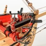 Chuck got a reaction from glbarlow in Sloop Speedwell 1752 by Chuck - Ketch Rigged Sloop - POF - prototype build
The hawse holes can be complex but if you spend a lot of time preparing and measuring it will go smoothly. Before I begin describing my process here is a look at the contemporary model. You can see many close up details here.
I started by preparing some new templates. They are very much like the other templates but I wanted to add some other reference lines to help me more with aligning the hawse holes. So these are the ones you want to use when you get this stage.
You will note a few things in that photo. First you will see the dashed vertical lines I added that extend up to the cap rail. These will allow you to mark the locations of the hawse holes on top of the cap rail. To do this I cut some painters tape to the width of the hawse holes and placed it on the cap rail using the template as a guide. The tape runs parallel to the keel across the cap rail.
You will also notice how I cut the hawse holes from the template so I could use it as a stencil after taping it to the hull. I also cut an opening to mark the location of the hawse hoods or naval hoods. These are the plates that sit over the planking. The template sits on top of the wales as before. The forward edge sits against the stem.
I of course cut away the molding strip on the hull before I taped the template in position. I dont want to forget to mention that. Then I traced the hawse holes onto the hull.
On the inboard side of the hull, I prepared another template specifically for the hawse holes. Note the dashed lines again that extend to the cap rail. This template was lined up with the tape I placed across the cap rail. This will be the path I plan to drill through the hull for the hawse holes. This was a lot of measuring and planning to come up with these templates but it all worked out well. Just trace the hawse holes on the inboard side as well. Note how the template is sitting on the deck which establishes the correct height...I hope.
I didnt take any pictures right after drilling the hawse holes. I cant believe I forgot to do it. But let me explain the process. I drilled them out using progressively larger drill bits. I drilled from both sides. I drilled half way through from the front and then switched to inboard. I drilled half way through until the holes met in the middle and the first small hole was clear and through. Then I switched to a slightly larger drill bit and repeated the process. I increased them until the hawse holes were almost full size and then I switched to a round file to clean them up and enlarge them further.
THE ENTIRE time while drilling from the outboard side I used the blue tape on the top of the cap rail to guide the drill bit at the same angle. Following the keel. The hawse holes are almost level in height inboard and outboard with only a slight upward angle needed as you drill from the outboard side. A very slight angle. Not to worry if its not exact because when you dill from the inboard side to meet the outside hole it should all meet up decently.
I touched up the red paint inboard and used a soft pencil to darken the insides of the hawse holes black...to represent lead or tin I suppose.
Next up was to add the Hawse hoods or Naval hoods on the outboard side. These are made in two layers. They are laser cut and on the outermost end is a laser etched detail. This small etched detail wouldnt be difficult to carve with a sharp chisel. But I just assume etch it onto the ends. This means you must clean up the laser char from this "stepped" detail. I used a small flat needle file. It doesnt have to be perfectly clean either. Just do the best you can. Mine isnt perfect by any means and this little bt of char will actually accentuate the carved detail. Look at the photo of the contemporary model to see it on the original. The parts on the left are not yet cleaned.
The two layers are glued together carefully. The circles for the hawse holes are registered together. But a little tip....while gluing the two layers you can actually pre bend the hoods so they will stay bent and curved once the glue dries. Its hard to see this in the photo but the one on the right is curved to almost match the hull curvature exactly. This will make it so much easier to glue onto the hull.
Here you can see the two layered assembly glued onto the hull. Please note that after gluing the two layers together the inside edge against the stem must be beveled. I also cut these pieces a but longer (not by much) so you can line them up with your hawse holes drilled through the hull. Just carefully bevel the edge a little at time until as you are test fitting it on the model it the hawse holes line up. The holes themselves are also slightly smaller on this so you will have even more wiggle room to enlarge them after this is glued on the model. I think they look pretty good and look quite a bit like the contemporary model.
Lastly...the bolster. This piece is slightly thicker and not long enough to bend easily. So I laser cut it on even thicker boxwood stock. Its easier to sand the curve into the back side rather than bend it to fit on the hull. Once the bolster sits nicely on the hull and the curve matches, you can sand the outside to match. This will leave the overall thickness at about 3/64". Maybe slightly more.
Round off the top edges and sides but dont touch the hawse hole cut-aways just yet. This will be done after you glue the bolsters on the model. You will notice the oddball shape of the hawse hole cut-aways. They dont look like half circles. This is on purpose. Remember the hawse holes are drilled through parallel to the keel. So these weird shaped half holes are shaped like l=this so you can file them to the proper shape. Use a round file to open them up to match the angle of your hawse holes through the bulwarks. I hope that makes sense. When initially gluing the bolster on the hull, line up the iboard side to match the profile of your hawse holes. Just like in the photo. Then use your file to shape them.
They will or should be opened up to look like this. The holes were touched up and blackened with a soft pencil.
-
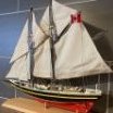 Chuck got a reaction from PaddyO in Sloop Speedwell 1752 by Chuck - Ketch Rigged Sloop - POF - prototype build
The hawse holes can be complex but if you spend a lot of time preparing and measuring it will go smoothly. Before I begin describing my process here is a look at the contemporary model. You can see many close up details here.
I started by preparing some new templates. They are very much like the other templates but I wanted to add some other reference lines to help me more with aligning the hawse holes. So these are the ones you want to use when you get this stage.
You will note a few things in that photo. First you will see the dashed vertical lines I added that extend up to the cap rail. These will allow you to mark the locations of the hawse holes on top of the cap rail. To do this I cut some painters tape to the width of the hawse holes and placed it on the cap rail using the template as a guide. The tape runs parallel to the keel across the cap rail.
You will also notice how I cut the hawse holes from the template so I could use it as a stencil after taping it to the hull. I also cut an opening to mark the location of the hawse hoods or naval hoods. These are the plates that sit over the planking. The template sits on top of the wales as before. The forward edge sits against the stem.
I of course cut away the molding strip on the hull before I taped the template in position. I dont want to forget to mention that. Then I traced the hawse holes onto the hull.
On the inboard side of the hull, I prepared another template specifically for the hawse holes. Note the dashed lines again that extend to the cap rail. This template was lined up with the tape I placed across the cap rail. This will be the path I plan to drill through the hull for the hawse holes. This was a lot of measuring and planning to come up with these templates but it all worked out well. Just trace the hawse holes on the inboard side as well. Note how the template is sitting on the deck which establishes the correct height...I hope.
I didnt take any pictures right after drilling the hawse holes. I cant believe I forgot to do it. But let me explain the process. I drilled them out using progressively larger drill bits. I drilled from both sides. I drilled half way through from the front and then switched to inboard. I drilled half way through until the holes met in the middle and the first small hole was clear and through. Then I switched to a slightly larger drill bit and repeated the process. I increased them until the hawse holes were almost full size and then I switched to a round file to clean them up and enlarge them further.
THE ENTIRE time while drilling from the outboard side I used the blue tape on the top of the cap rail to guide the drill bit at the same angle. Following the keel. The hawse holes are almost level in height inboard and outboard with only a slight upward angle needed as you drill from the outboard side. A very slight angle. Not to worry if its not exact because when you dill from the inboard side to meet the outside hole it should all meet up decently.
I touched up the red paint inboard and used a soft pencil to darken the insides of the hawse holes black...to represent lead or tin I suppose.
Next up was to add the Hawse hoods or Naval hoods on the outboard side. These are made in two layers. They are laser cut and on the outermost end is a laser etched detail. This small etched detail wouldnt be difficult to carve with a sharp chisel. But I just assume etch it onto the ends. This means you must clean up the laser char from this "stepped" detail. I used a small flat needle file. It doesnt have to be perfectly clean either. Just do the best you can. Mine isnt perfect by any means and this little bt of char will actually accentuate the carved detail. Look at the photo of the contemporary model to see it on the original. The parts on the left are not yet cleaned.
The two layers are glued together carefully. The circles for the hawse holes are registered together. But a little tip....while gluing the two layers you can actually pre bend the hoods so they will stay bent and curved once the glue dries. Its hard to see this in the photo but the one on the right is curved to almost match the hull curvature exactly. This will make it so much easier to glue onto the hull.
Here you can see the two layered assembly glued onto the hull. Please note that after gluing the two layers together the inside edge against the stem must be beveled. I also cut these pieces a but longer (not by much) so you can line them up with your hawse holes drilled through the hull. Just carefully bevel the edge a little at time until as you are test fitting it on the model it the hawse holes line up. The holes themselves are also slightly smaller on this so you will have even more wiggle room to enlarge them after this is glued on the model. I think they look pretty good and look quite a bit like the contemporary model.
Lastly...the bolster. This piece is slightly thicker and not long enough to bend easily. So I laser cut it on even thicker boxwood stock. Its easier to sand the curve into the back side rather than bend it to fit on the hull. Once the bolster sits nicely on the hull and the curve matches, you can sand the outside to match. This will leave the overall thickness at about 3/64". Maybe slightly more.
Round off the top edges and sides but dont touch the hawse hole cut-aways just yet. This will be done after you glue the bolsters on the model. You will notice the oddball shape of the hawse hole cut-aways. They dont look like half circles. This is on purpose. Remember the hawse holes are drilled through parallel to the keel. So these weird shaped half holes are shaped like l=this so you can file them to the proper shape. Use a round file to open them up to match the angle of your hawse holes through the bulwarks. I hope that makes sense. When initially gluing the bolster on the hull, line up the iboard side to match the profile of your hawse holes. Just like in the photo. Then use your file to shape them.
They will or should be opened up to look like this. The holes were touched up and blackened with a soft pencil.
-
 Chuck reacted to druxey in Sloop Speedwell 1752 by Chuck - Ketch Rigged Sloop - POF - prototype build
Nice, Chuck, and theoretically foolproof!