michael mott
-
Posts
5,200 -
Joined
-
Last visited
Content Type
Profiles
Forums
Gallery
Events
Everything posted by michael mott
-
 Ed you clearly show that sequencing some of the operations is something that only comes with experience. I wonder how many times some of us think, "I wish I had thought about this job earlier when things were easier to hold or not connected to something else" The picture showing the holes being drilled in a square spar before it is shaped and rounded brought this home to me. The shot of all the spars also reminded me if this. Michael
- 3,618 replies
-
- 7
-

-
- young america
- clipper
- (and 1 more)
-
Javier thank you for showing us the beginning of your next build I am looking forward to seeing how you progress with this build. Michael
-
Hello Daniel, I just found your build. What a superb job you are doing, I am inspired by the way you are able to use manual control on your mill to create a curve, I know that it is not easy to do. Your assembly of the frames looks like a very good way to clamp them. The exploded view of the successively smaller frames for the bow is almost like an installation sculpture. beautifully executed wood work. I shall continue to follow along. Michael
-
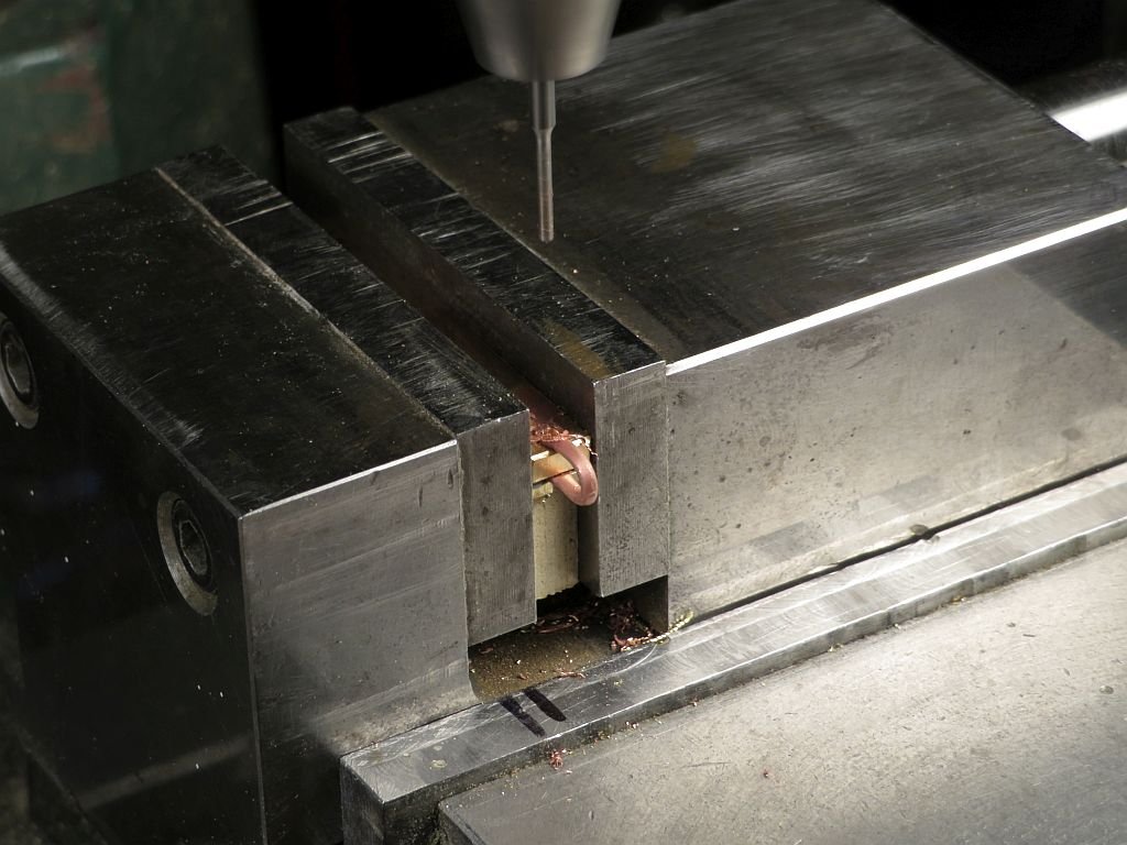
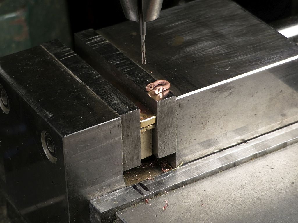
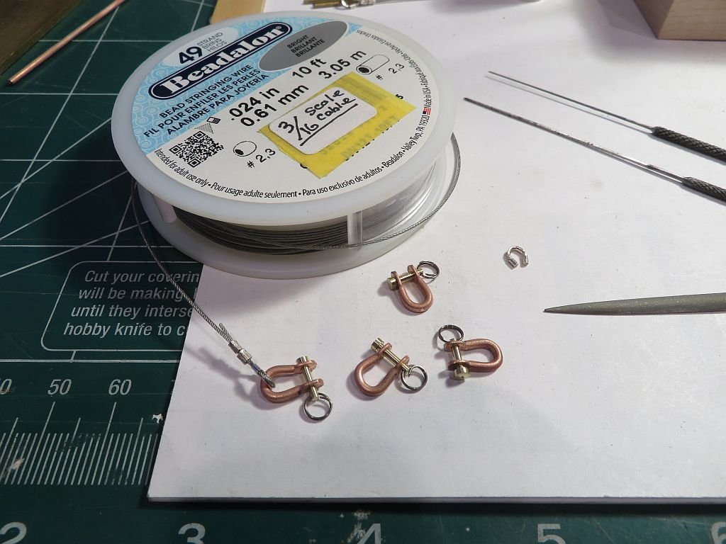
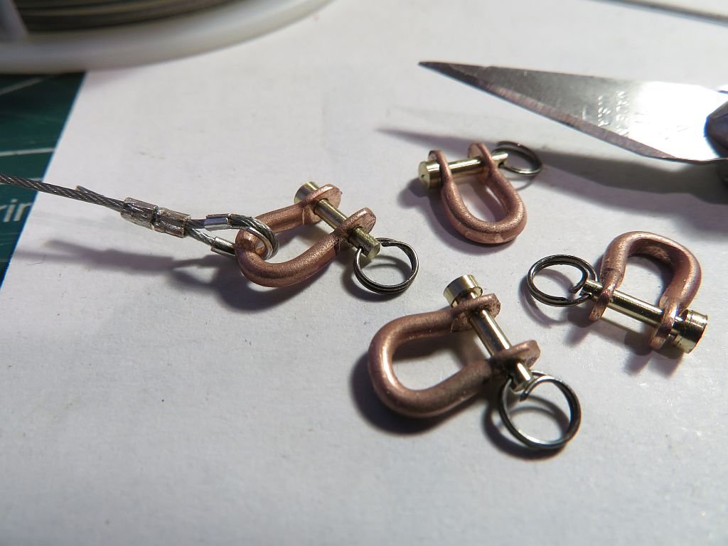
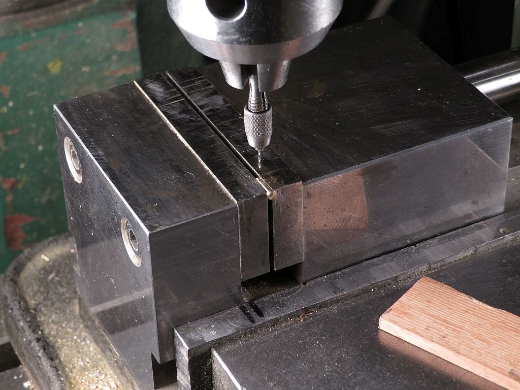
Thanks Pat Not a lot to show for today, I am thinking of some steel cables for the topmast shrouds so did some experimenting with some Beadalon wire and made 4 new shackles. from some .060 copper wire. I soldered up a small fixture for drilling the .056 holes through the shackles The pins were turned from some inexpensive 3/16 brass rod from Home Depot. I am impressed at the free machining quality of this brass, which allowed for me to cut the diameter in one pass, this ensured that the work was supported all the way by the 3/16 section as it was being reduced. I backed out the cutter and cut a shoulder that was .030" larger in diameter, then parted off the pins for drilling the #78 retaining ring hole. I filed a small flat with a #8 cut file as a land for the drill. which I supported pretty close to the cutting edge. That's it for today. Michael
-
Very Nicely done Ab the final results are really lovely the photograph has a great mood to it reminds me of the Dutch painters who loved all the detail in their oil paintings Michael
- 65 replies
-
- 5
-
-
- fish hooker
- fishing
- (and 2 more)
-
Congratulations of getting the model into its case Nils you have done a masterful job of the display. Michael
- 692 replies
-
- 3
-
-
- eagle of algier
- chebec
- (and 2 more)
-
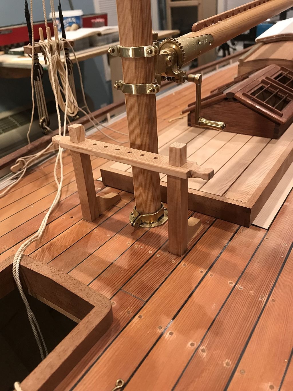
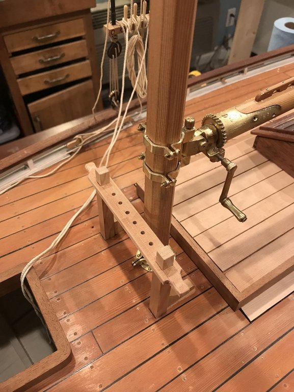
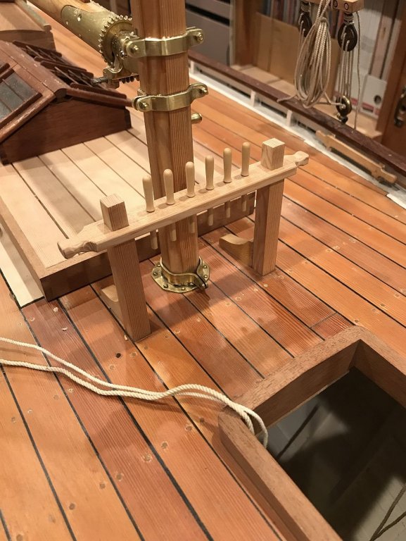
Tim I have spent countless hours pouring over just about every detail of "Integrity" it is a beautifully conceived yacht. and to answer you question about the model I will probably give it away eventually. Thanks Druxey, I really did not want to go through the motions of making a fourth topmast. Kees thanks for you kind words Ab thanks for your words and yes the details are for me, the most fun and challenging part. It again reminds me of Remco's byline that I'm paraphrasing if one treats every part as a model in its own right one will get there eventually. Steve yes this will be a great experience hopefully a lot of fun too. Thanks Dowmer I was just too tired to remember last light. I also forgot to add the pictures of the new pin rail that is almost complete. it is made from fir and i was able to get one more pin in by just squeezing them a 1/2 inch closer together. Scale that is of course. I will put a small brass cap on the tops of the uprights and round off the center part of the extensions that come through the rail. Michael

-
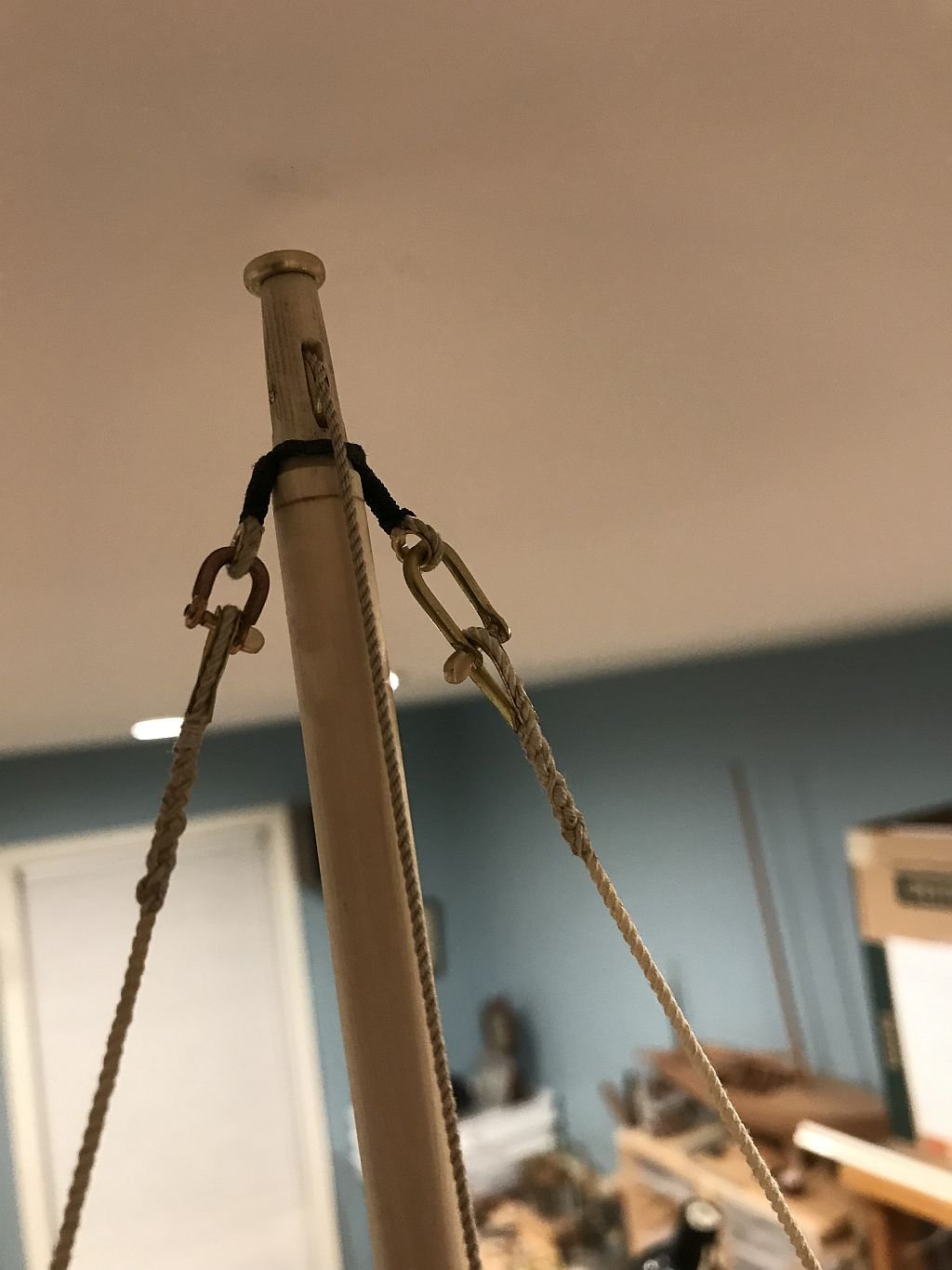
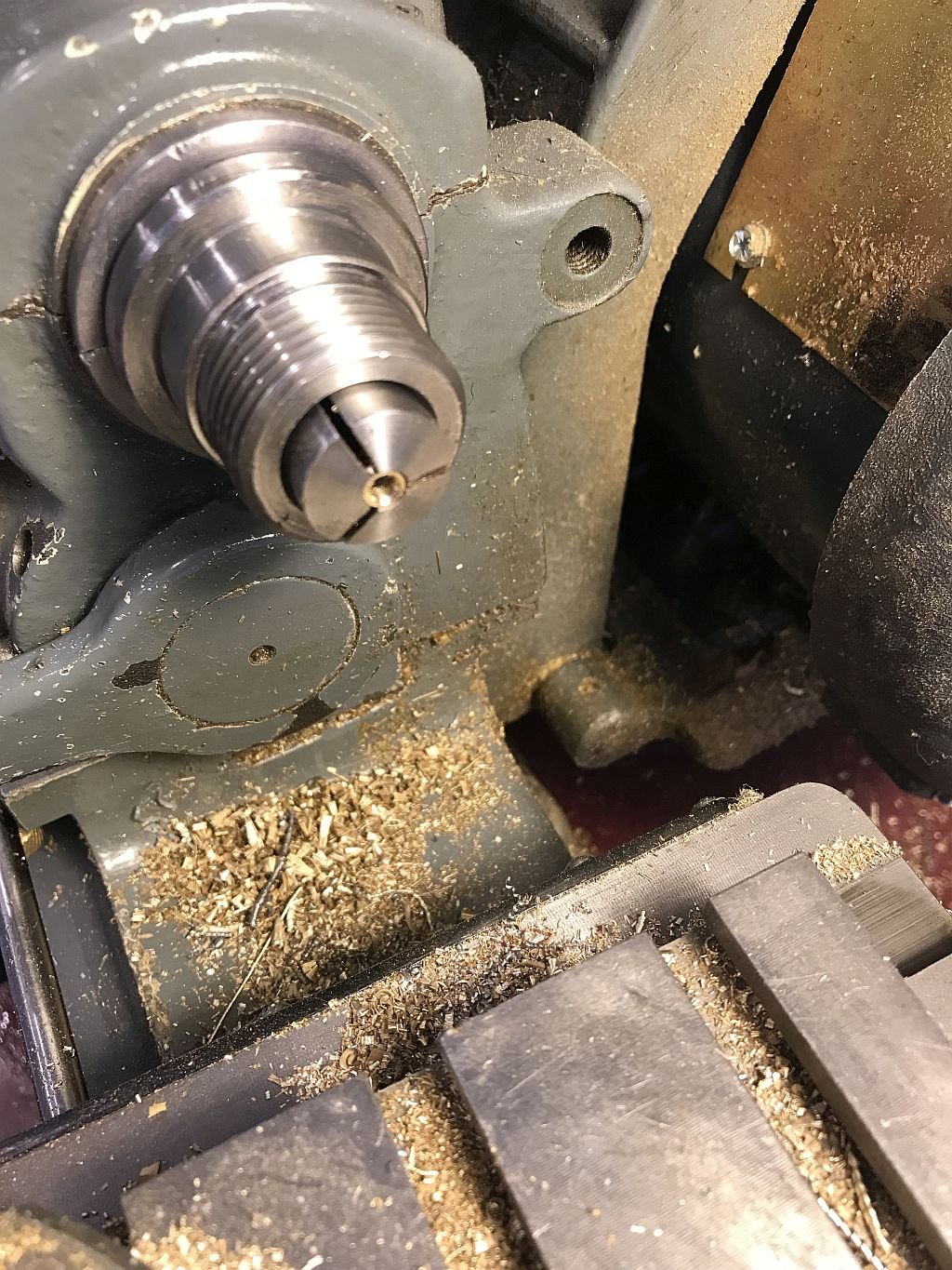
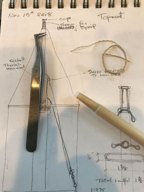
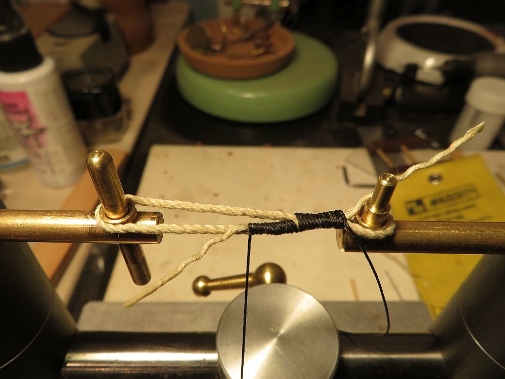
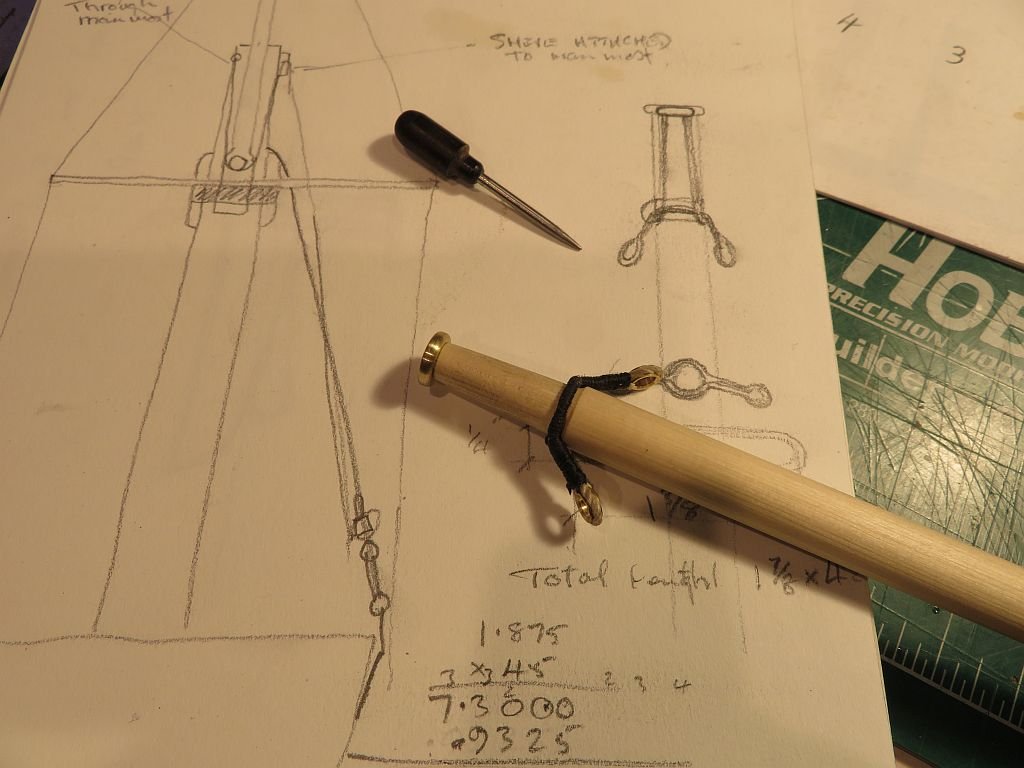
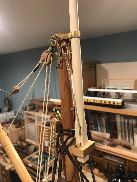
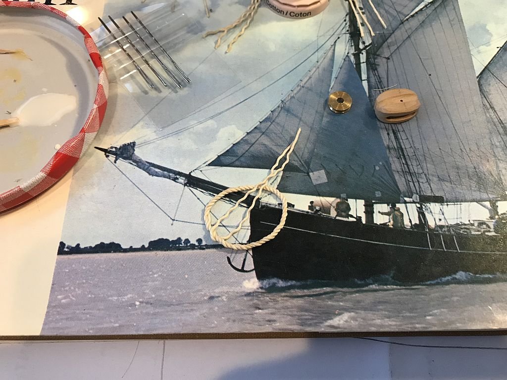
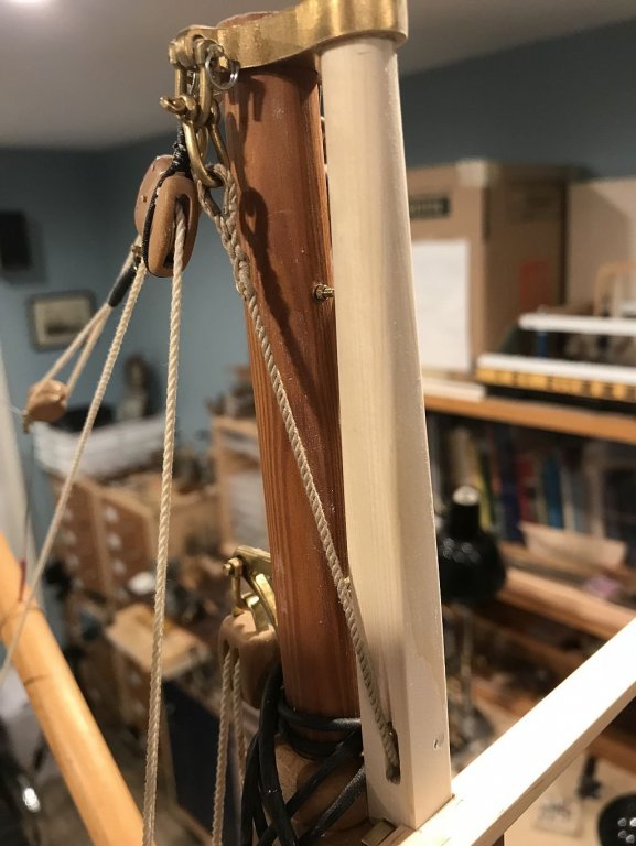
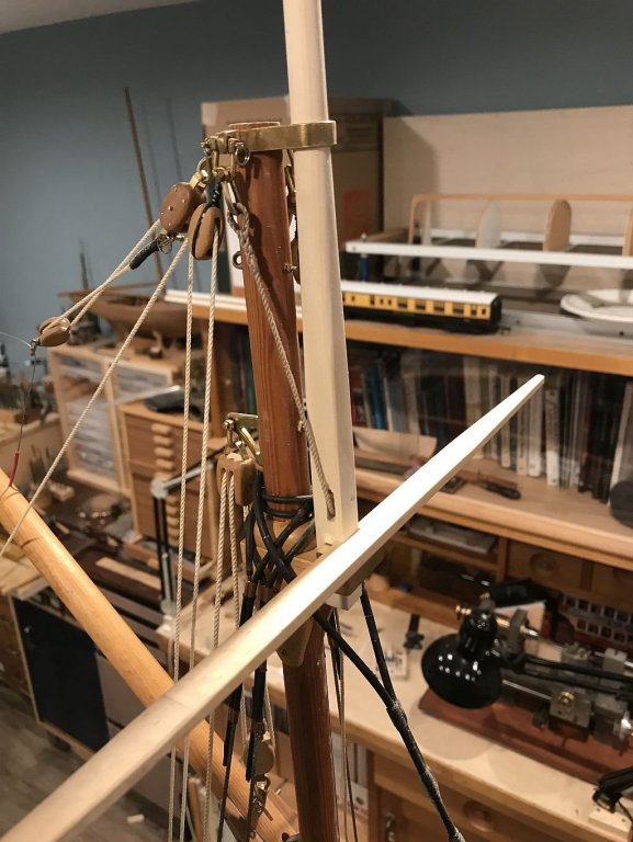
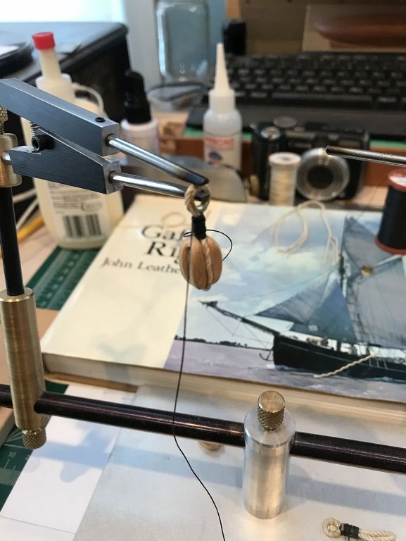
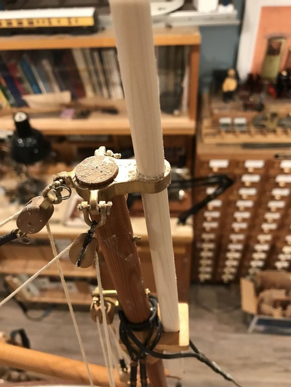
Thanks for all the likes and fine comments More work on the topmast today. first i needed to make the small strop for the shrouds at the top. the first part was to make a ring by unwinding some rope making a length of about 8 1/2 inches long then recoiling itself into a ring. Once the ring was formed then the thimbles were placed on some new arms for the third hand. and then some "whipping" can't think of the proper term at this time of the night. Then the top of the topmast was ready for the "harness" notice the line just below the harness, the result of the error of cutting the slot for the top sheave at 90 degrees to where it should have been cut. I slipped the topmast through the headstock of the Myford after several wraps of masking tape to protect the wood, and cut a rebate about 1/8th inch wide down to 5/32 diameter then cut off the top with the jewelers saw. then bored a shallow hole the same diameter. coated both parts with a thin film of ACC once that had set I pushed the parts together with the sheave fore and aft then gave another shot of ACC to fix it in place. The shackles are different the small one is new today and the longer one from the bin of shackles. Once the shrouds were connected, I hoisted the mast again, and laid them over the ends of the spreader to get the position of the lower tackle. Tomorrow I shall finish the ends or the spreader. Michael


-
Igor that looks wonderful! If you have too many of these small models and they are filling up your display space you can always send it to me, I would send you my address if you need it. Please! Michael
- 185 replies
-
- 4
-
-
- jolie brise
- pilot cutter
- (and 2 more)
-
Johann, Thank you for adding the scale it helps a great deal. your ropes look very good. Michael
-
This surprised me, I really had no idea how complex these masts are. incidentally I have re ordered a copy of Longridge's book the anatomy of Nelson's Ship, somehow my original copy has gone AWOL. Ed I am just amazed by how much detail you are putting into this model at such a small scale, it is a masterpiece for sure. Michael
- 3,618 replies
-
- 2
-
-
- young america
- clipper
- (and 1 more)
-
Thanks for all the kind remarks. I made a short video of the topmast being hoisted. I spent a long time getting the topmast to hoist up properly which also included making a couple of sheaves that are attached to the mast. The following sequence should be self explanatory. Michael

-
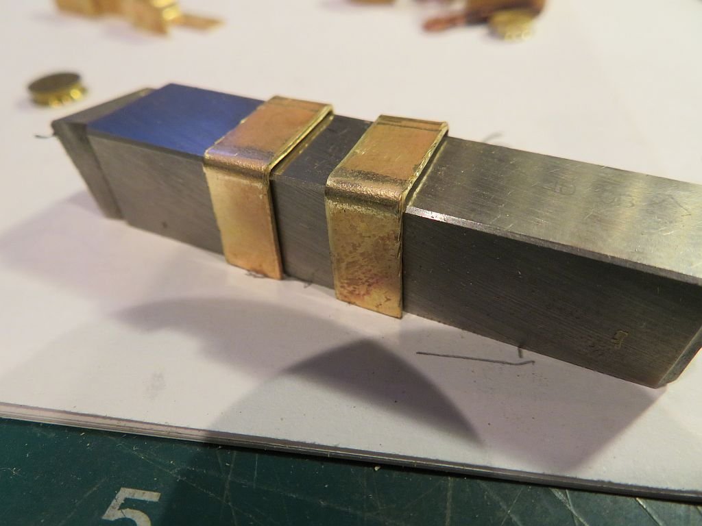
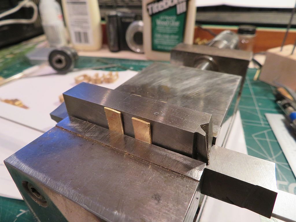
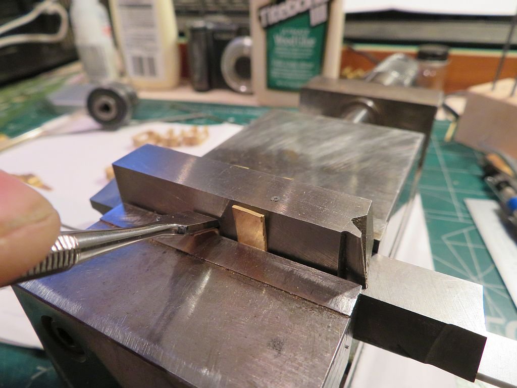
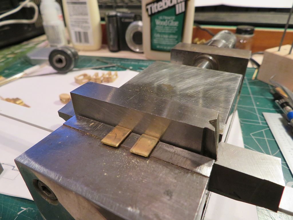
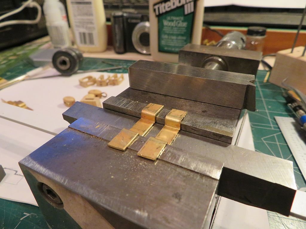
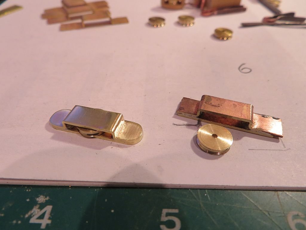
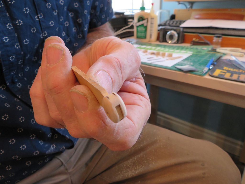
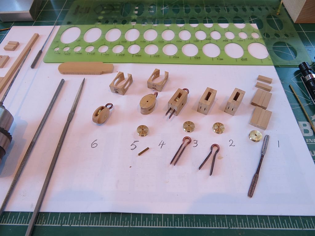
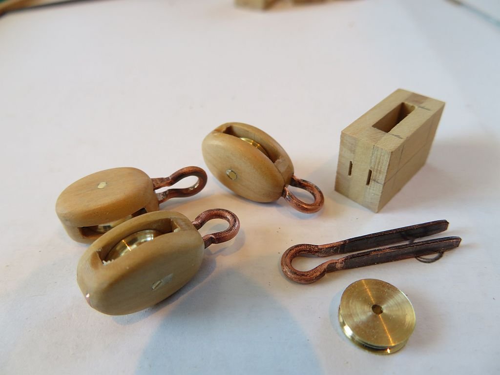
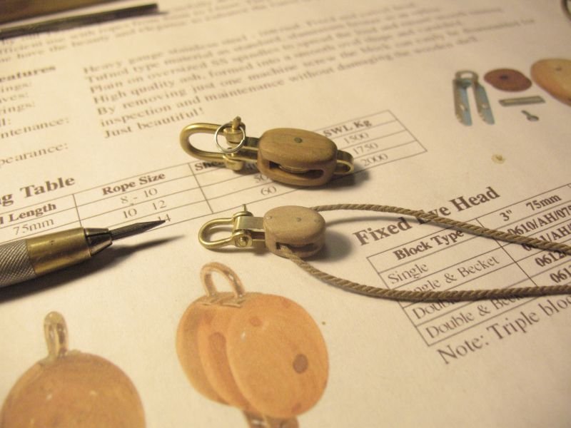
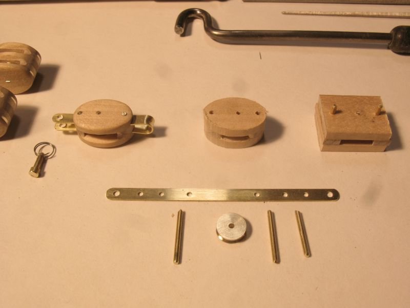
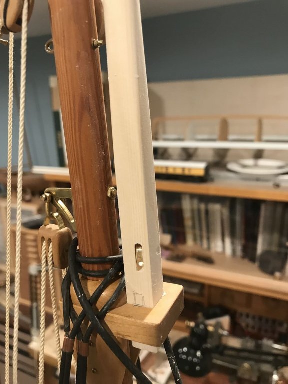
Thanks for all the visits and likes they are appreciated. Mark, Steve answered your question for me. The one thing I do have to do to finish the topmast shape, is to make the transition from the square section to the round section much more abrupt, at the moment it is too long and the rope binds there only needs to be a short section where the rope lays in a groove to prevent the square section from binding. Needing some more blocks and working at different ways to produce a block that will be easy to make and economical in terms of time and materials. It is fun to explore new styles and ways of doing things. back in 2013 I made some blocks this way. using some 1/8" x .025" strip if my memory serves me correctly. The wood was maple and the sheave about 3/8ths diameter. I had been looking at the pictures in this catalogue under these blocks. and at the time I had not sorted out how to achieve the metal rounded top on them. Fast forward to this week, and having looked at all sorts of wonderful work of rigging parts by Ed Tosti, who uses copper for many of his fittings. I woke up with the idea that maybe I could use copper for this rounded top instead of brass. So I took some heavy copper wire approx 1/16th diameter and annealed it, then flattened each end. this looked promising. I cut a few more lengths and flattened the ends leaving approx 1/2" in the middle that was still round This time I flattened the ends in a single squash but needed to anneal it a few times to get it thin enough .020" the next picture shows the sequence to make these new blocks this time the wood is South American boxwood or Castello I cut some strips that were 5/8" wide by 3/32" thick then I stripped off a 1/8" strip from it. the wide section had a 1/8th x .025" trough cut down the center. they are just visible on the left side. Beginning on the right side 1) wood blanks cut from the strips, sheave cut from 3/8 brass rod bored out to .054", and flattened copper. 2) the wood has been glued together with Tightbond III glue, the copper as been folded by hand around a 3/32" steel rod. 3) the copper was pinched in the vice with a slab of 3/32" brass filler between the flattened ends and the 3/32" steel rod as the guide for depth. 4) the copper was slipped into the slots in the assembled block, and then drilled through with a .046" bit this hole was then opened up gradually with the tapered reamer which was held in a small three jaw chuck to save my fingers from getting blistered from twisting the small knurled handle of the reamer. 5) after the hole was drilled the copper was pulled out again and the elipse template was used to draw the shape of the block, which was then cut out with the jewelers saw. 6 is the final block after using a holder to sand and shape the individual blocks. This is the small holder made from the same stock thickness as the layers of the block. And finally three of the blocks they are not identical and I am OK with that as I make more they will become more consistent. Michael
-
I like the way you have slotted the deck pieces. Michael
- 65 replies
-
- 2
-
-
- fish hooker
- fishing
- (and 2 more)
-
Getting Back Into The Hobby After 45+ Years
michael mott replied to Tom in NC's topic in New member Introductions
Welcome back to the world of modelbuilding Tom, I look forward to seeing your future models. Michael -
Mark the photos of your hull upside down show what a fine job you have done on the frames and fairing. Michael
-
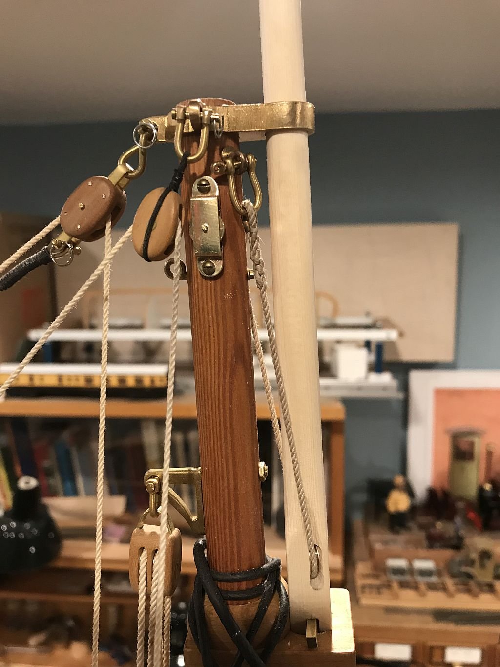
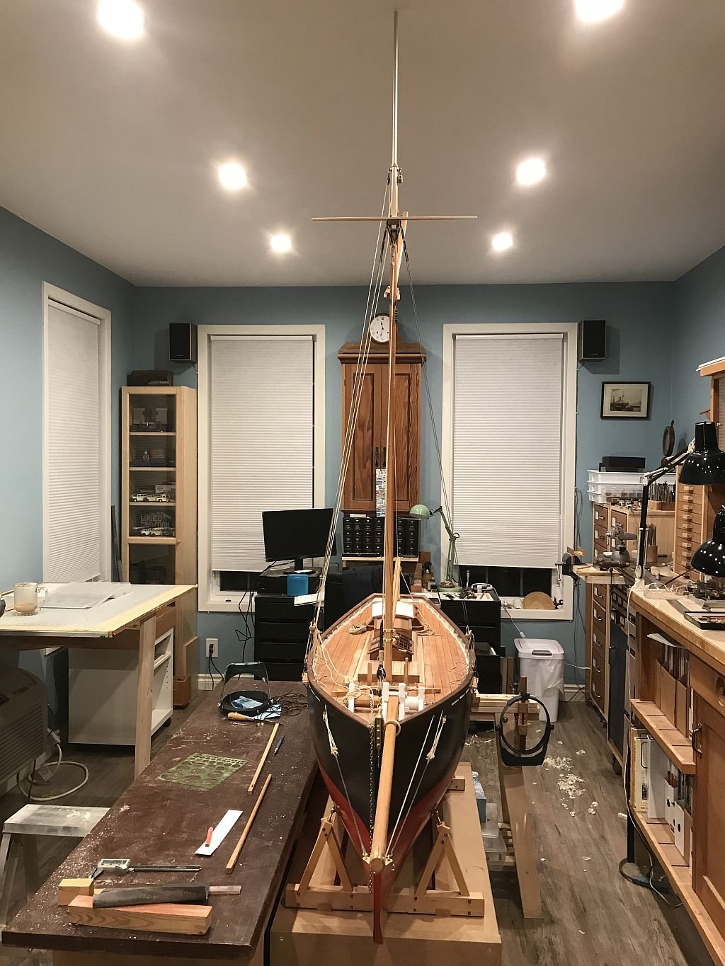
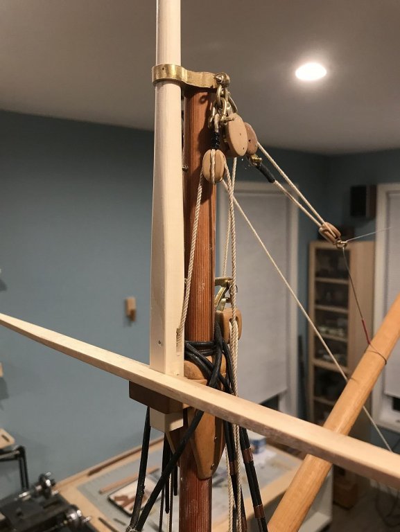
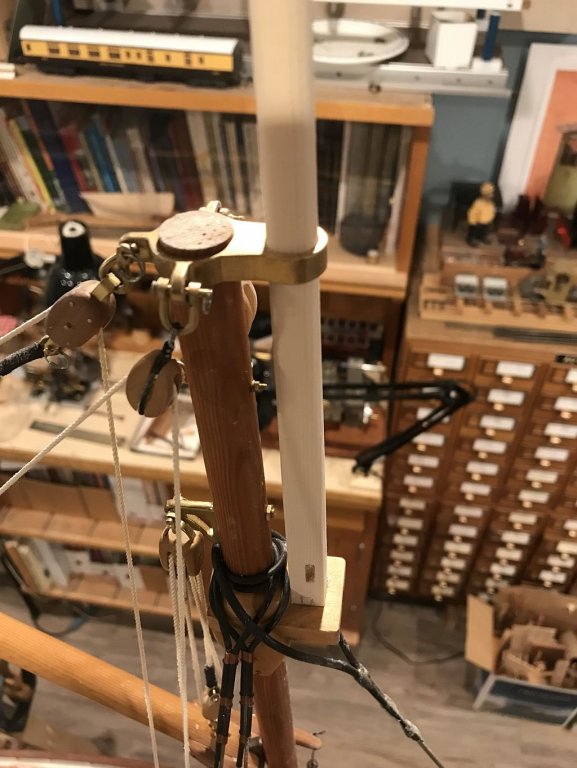
glad I'm not having to get paid for this, I would be working for nothing. I have spent almost two days mucking about with making strops and thimbles for a block or two to hoist the topmast I will need to do a bunch more work on the main mast to fit sheaves and fittings for attaching blocks. I will also need to do some more shaping so that the rope doesn't bind when going through the bolster fitting. The thimbe in the rope was spiced some time ago so I did not have to do it. the rope and shackles are temporary so that i can sort out the shape and where to lay the fall. Michael

-
Thanks Nils that does make sense. Incidentally I ordered the book that Jurgen Willing referred to in the description of the build. Michael
- 692 replies
-
- 3
-
-
- eagle of algier
- chebec
- (and 2 more)
-
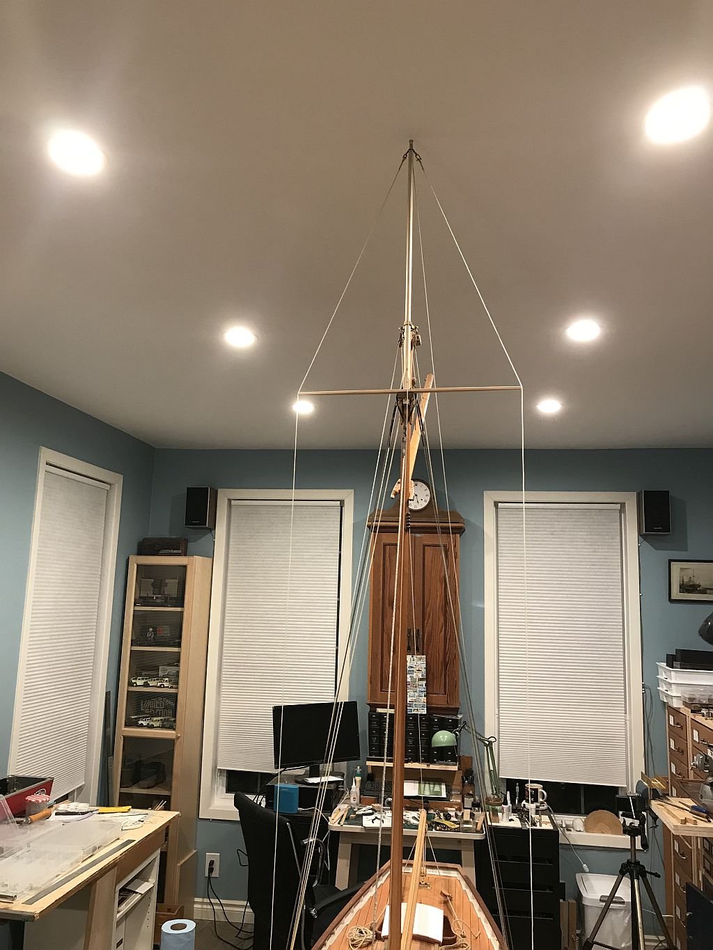
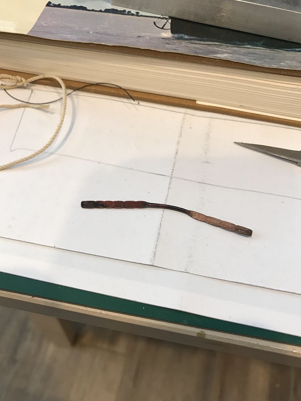
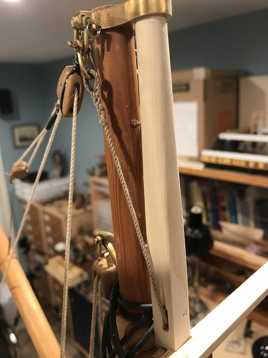
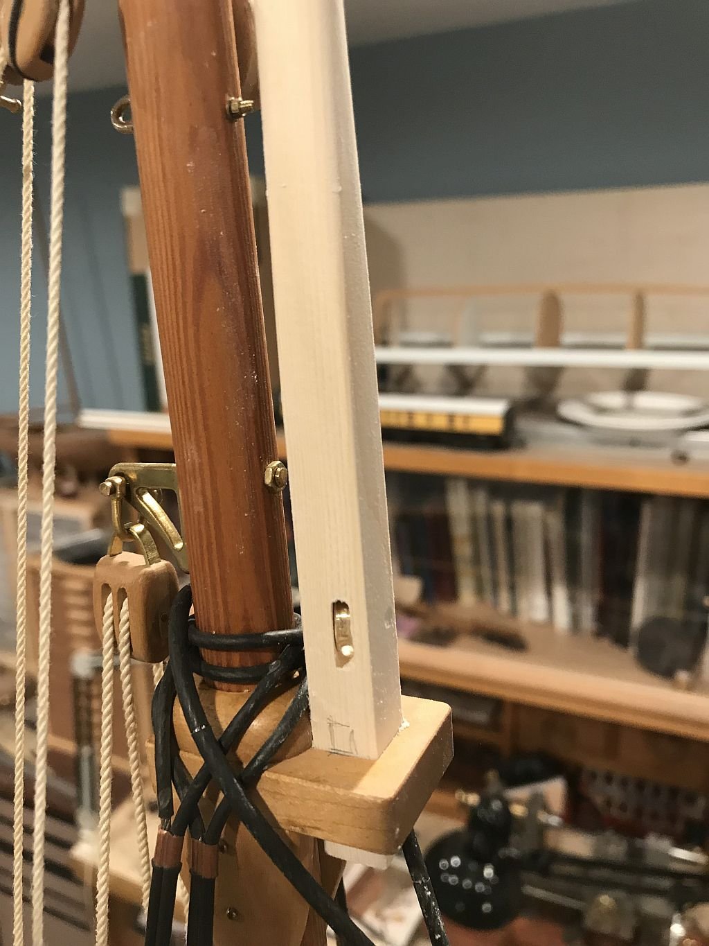
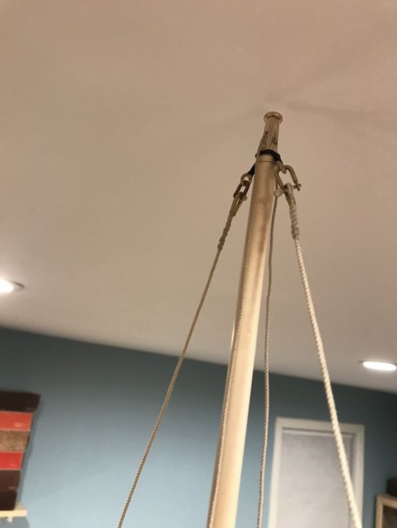
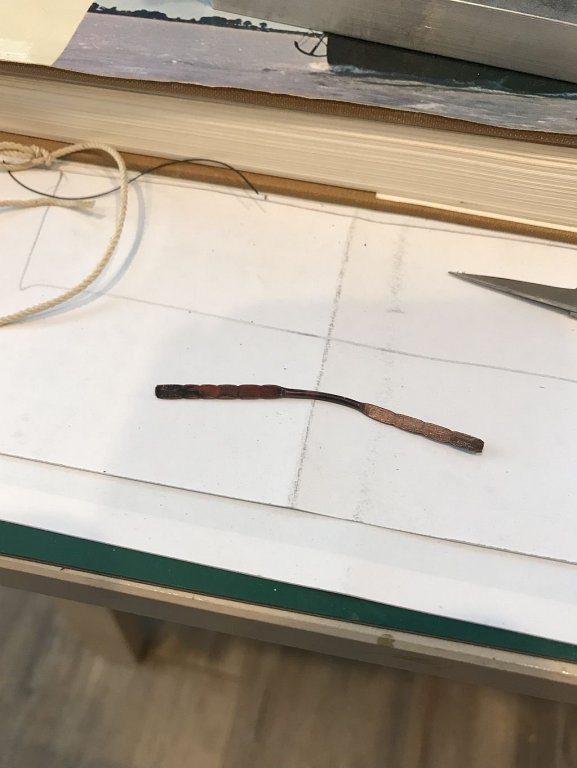
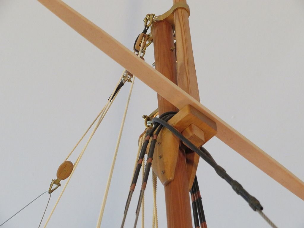
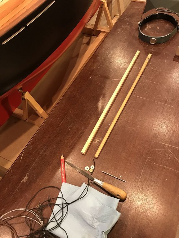
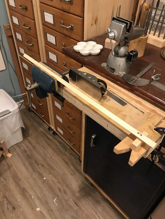
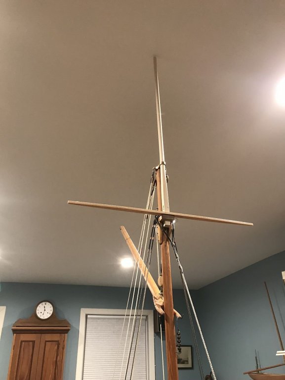
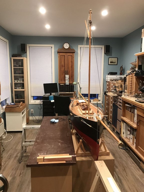
I worked on the topmast today and that led to reading up on the topmast shrouds and so a cross tree was made out of some fine grained Pine. the first picture shows the new spreaders for the topmast shrouds. When I machined the hole for the bottom sheave to set up the hoisting rig I did not get the hole right, it was too long ans off centre so I cut a new stick and decided to cut in the sheave slot before shaping it. screw up #2 I made the slot the same length. I embarked on stick #3 this one from some really nice clear spruce I got the bottom sheave done correctly and then started to shape the topmast. Using the drafting template for roundness once i got close to the diameter I needed, I began the task of final fitting in order to reach I rolled over the other bench as a platform to stand on. This made the fitting easier. The topmast has to rise up high enough for the sheave to clear the bolster and leave enough room for the fid. There were a lot of fitting trials befor the sheave cleared. and I seemed to have a problem nearing the finish, then it occurred to me that I was hitting the ceiling because I had left the topmast a little longer. One i removed about 1/2 inch from the top I was able to hoist the mast high enough. Feels a bit precarious working up so high. and an overall shot of the days work. That's all for now Michael

-
Thanks Dick. Michael
-
Nils I looked up your picture and have some questions about the model in one of the pictures there appears to be a large spar hung on the mast in front of the spreaders is this a spinnaker pole? Michael
- 692 replies
-
- 3
-
-
- eagle of algier
- chebec
- (and 2 more)
-
Dick my first visit, this looks very interesting. What wood are you using? If you already mentioned it my apologies for missing it. Michael
- 263 replies
-
- 2
-
-
- nave tonda
- round ship
- (and 2 more)
-
Good morning Nils, I just finished catching up with your model. Again you have shown a wonderful rendition of your subject that is alive with character and demonstrated skills. I shall have to try your sailmaking methods, I thought the bolt rope method was very clever. Congratulations on the completion. You mentioned some time ago that one of your favourite boats was the cutter Genesta, it would be nice to follow you build it, but you probably already have the next one sorted. Michael
- 692 replies
-
- 2
-
-
- eagle of algier
- chebec
- (and 2 more)
-
Sharpie by Jim T - Scale 1:16 - SMALL
michael mott replied to Jim T's topic in - Build logs for subjects built 1851 - 1900
Very nicely done Jim, are the plaks lapped at all or are they butted only? I could not tell from the pictures. Michael